Page 1
INTERNATIONAL JOURNAL ON SMART SENSING AND INTELLIGENT SYSTEMS VOL. 8, NO. 1, MARCH 2015
65
L-SHAPED CANTILEVER PARALLEL - PLATE MEMS
ACCELEROMETER DESIGN PARAMETERS USING A
GRAVITATIONAL SEARCH ALGORITHM
Souad Oukil Abdelmadjid Boudjemai Nabil Boughanmi
Electrical Engineering
Faculty USTOMB, BP 1505
El M’Naouar Oran, Algeria.
[email protected]
Centre of Satellite
Development (CDS), Space
Technology Research
Division BP.: 4065 Ibn
Rochd USTO Oran, Algeria,
[email protected]
Electrical Engineering
Faculty USTOMB, BP 1505
El M’Naouar Oran, Algeria
[email protected]
______________________________________________________________________________
Submitted: Nov. 12, 2014 Accepted: Jan. 7, 2015 Published: Mar. 1, 2015
Abstract- Due to their small size, low weight, low cost and low energy consumption, MEMS (Micro
Electro-Mechanical Systems) accelerometers have achieved great commercial success in recent
decades. The objective of this paper is to find the optimum design for a typical MEMS accelerometer,
which satisfies a set of given constraints. Due to the complex nature of the problem, a gravitational
search algorithm (GSA) is developed for optimization. The GSA attempts to optimize the inter-plate gap
while satisfying all other engineering goals. The model was constructed in Msc Patran and Nastran
software were calculated and model’s response was found. In this paper the optimal design from the
theoretically derived gravitational search algorithm is compared to finite element model in order to
ascertain its accuracy and verify the results.
Index terms: Power system; MEMS; capacitive accelerometer; optimization; proof-mass; L-shaped beam;
GSA; frequency.
Page 2
Souad Oukil, Abdelmadjid Boudjemai and Nabil Boughanmi, L-SHAPED CANTILEVER PARALLEL – PLATE MEMS ACCELEROMETER DESIGN PARAMETERS USING A GRAVITATIONAL SEARCH ALGORITHM
66
I. INTRODUCTION
Manufacturing technology microsystems uses micro-technologies for manufacturing integrated
circuits including photolithography steps, deposits, and prints. MEMS are currently used to make
ink jet printers, accelerometers, inertial sensors, pressure sensors, micro-mirrors, micro-fluidic
pumps (figure 1a). New applications such as RF resonators and laboratories on a chip are being
developed. MEMS cover various applications in the field of industrial, medical, automotive,
telecommunications; defense [1, 2] (figure 1b).
Parallel plate capacitors are widely used in various applications, such as RF devices [3], variable
capacitors [4], accelerometers [5, 6, 7], micro-mirrors, and active vibration isolators [8]. One
issue that is inherent to all parallel plate actuators (PPA) is the condition of pull-in. Pull-in is the
inability of a PPA to be electrostatically actuated beyond one third of its rest gap distance without
becoming unstable. Most PPA devices in widespread use are designed so that they only operate
while in an open-loop stable range of motion. These devices must be designed so that they are not
actuated beyond this point unless additional circuit is added to prevent pull-in from occurring.
(a) (b)
Figure 1. MEMS evolution: (a) Maturity of MEMS devices [9]; and (b) MEMS sensor by
applications [10]
MEMS accelerometers were proposed in 1979 in a paper on a batch-fabricated silicon
accelerometer [11]. MEMS based accelerometers are receiving much interest since last few years
(see figure 2) [12]. Cost effective and small MEMS accelerometers need for more cost efficient
and miniaturized accelerometers are much more demanding in the present scenario. A number of
Page 3
INTERNATIONAL JOURNAL ON SMART SENSING AND INTELLIGENT SYSTEMS VOL. 8, NO. 1, MARCH 2015
67
different accelerometers are available in the market such as capacitive [13], piezoresistive [14]
and piezoelectric [15].
(a)
(b)
Figure 2. Evolution of MEMS Accelerometers: (a) Analog devises accelerometer (automotive);
and (b) STMicroelectronics accelerometer (consumer)
Micromachined accelerometers are extensively used in different areas such as automotive,
inertial navigation, guidance, industry, space applications etc (see figure 2). Because of low cost,
small size, low power, and high reliability. Among various sensing schemes of accelerometers,
capacitive sensing is generally preferred since it provides low temperature dependency, high
voltage sensitivity, low noise floor, and low drift. Capacitive accelerometers require special
readout electronics to sense the capacitance change and to operate in force-feedback for increased
operation range and linearity. With the force-feedback circuit, the overall system becomes
complicated because of having both mechanical and electrical components defining the overall
performance [16].
In particular the L-shaped cantilever parallel - Plate MEMS are widely used in many area and
applications (see figure 3). Many authors have been demonstrating such configuration which
gives better sensitivity [17] and suitable for sensing applications. Vincas Benevicius et al.
presented in their work an identification of capacitive MEMS accelerometer Structure parameters
for human body dynamics measurements, which is used widely in medical applications [18]. D
Ozevin et al. consider a device containing an array of MEMS transducers with different resonant
Page 4
Souad Oukil, Abdelmadjid Boudjemai and Nabil Boughanmi, L-SHAPED CANTILEVER PARALLEL – PLATE MEMS ACCELEROMETER DESIGN PARAMETERS USING A GRAVITATIONAL SEARCH ALGORITHM
68
frequencies used for structural health monitoring [19]. MEMS have been proposed for a number
of space applications, as lighter and smaller replacement parts or as entire new systems, or as a
means to provide affordable redundancy. The L-shaped MEMS sensors are used also in space
applications such as sensor placement for structural health monitoring (SHM), damage detection
and fault characterization [20, 21, 22, 23, 24, 25].
Figure 3. L-shaped cantilever parallel - Plate MEMS accelerometers.
The paper is organized as follows: Parallel - Plate MEMS Accelerometer model are given in
Section 2, The gravitational search algorithm is presented in Section 3, Formulation of the
objective function of accelerometer model and its validation, are presented in Section 4. Finite
element simulations and Modal Analysis of L-shaped cantilever parallel - Plate MEMS
accelerometers is given in Section 5. Concluding remarks are provided in the final Section 6.
II. PARALLEL - PLATE MEMS ACCELEROMETER MODEL
II.1 MEMS Accelerometer Mathematical model
The L-shaped cantilever parallel - Plate MEMS accelerometer models used the simulation are
shown in Figures 4 and 5, in which the central masses are suspended by flexures that are
anchored on substrates. When the structures are exposed to acceleration a , as shown in Figure 4
Page 5
INTERNATIONAL JOURNAL ON SMART SENSING AND INTELLIGENT SYSTEMS VOL. 8, NO. 1, MARCH 2015
69
and 5, whose frequency is much less than the natural frequency of the structure, the masses will
be displaced by z for the spring force of the flexures to balance the inertial force. In Figure 5, a
plate of mass m and area A is suspended by L - shaped flexures to reduce the nonlinear factor.
The plate may be perforated to control the damping factor (or quality factor).
Figure 6 show the design model.
Figure 4. Without Perforated plate. Figure 5. With perforated plate.
Figure 6. Design model of MEMS Accelerometer
Mathematical model of the designed L-shaped cantilever parallel-plate MEMS accelerometer is
similar to vibration equation in [26]. When acceleration is applied to a mass-spring inertial
system in the sensing direction, it can be described as follows:
mz +cz +kz=Fi (1)
where m is the proof mass, c presents the damping coefficient, k is the spring constant of the
springs, z is the relative displacement of the proof mass and Fi is the applied force which
includes electrostatic force and inertia force.
Page 6
Souad Oukil, Abdelmadjid Boudjemai and Nabil Boughanmi, L-SHAPED CANTILEVER PARALLEL – PLATE MEMS ACCELEROMETER DESIGN PARAMETERS USING A GRAVITATIONAL SEARCH ALGORITHM
70
We can set up the model (a parallel - plate actuator) shown in figure 7a to analyze the behavior of
the suspended plate. In the model, a suspended plate of mass m and area A is supported by a
spring of stiffness k and damper of damping coefficient c , while a voltage less than a pull - in
voltage is applied between the suspended and base plates. If the frequency of the applied
acceleration a is much less than the natural frequency at V , the spring force balances the inertial
force due to the acceleration, and the gap between the plates is changed from the initial gap h0 to
ha [27].
(a) (b)
Figure 7. Model of parallel-plate accelerometer
Referring to the free - body diagram of Figure 7b, we obtain the force equilibrium equation:
k h0-ha = 1
2
εA
ha2 V2+ ma (2)
For convenience, equation (2) may be expressed in a dimensionless form which is given by
Ha3- 1-I Ha
2+ G=0 (3)
Where
Ha= ha
h0, G=
1
2
ε A
k h03 V2 , I=
ma
kh0
The stable solution of the dimensionless force equilibrium equation, (3) is expressed by
Ha= 1-I
3 1+2 cos
1
3 cos-1 1-
2
(1-I)3
G
Gpi (4)
Where Gpi= 4/27.
Noted from equation (4) that the two independent parameters I and G affect the dimensionless
gap Ha. In Figure 8 the gap Ha is plotted against the inertial force I for the normalized
electrostatic force G/Gpi = 0, 0.1, 0.2, 0.4, 0.6, 0.8 and 0.95. For G/Gpi = 0, the dimensionless gap
Page 7
INTERNATIONAL JOURNAL ON SMART SENSING AND INTELLIGENT SYSTEMS VOL. 8, NO. 1, MARCH 2015
71
Ha decreases linearly from unity to zero because there is no electrostatic force acting on the
suspended plate. Physically, this means that the mass moves by maximum displacement (i.e., the
initial gap h0) and touches the base electrode of Figure 7a as the maximum acceleration of kh0/m,
corresponding to I = 1, is applied. For G/Gpi ≠ 0, the nonlinear electrostatic force is exerted on the
suspended plate and then the parallel - plate actuator can experience pull - in. When the
normalized electrostatic force G/Gpi increases from zero to unity, the starting gap is lowered from
unity and the pull - in gap varies from zero (i.e., the suspended plate touches the base plate) to
2/3.
As the inertial or electrostatic force increases from zero to its pull - in value, the argument of the
inverse cosine in (4) varies from unity to negative unity. Therefore, the suspended plate, exposed
to the acceleration a, is in a stable or critical condition if the following condition is satisfied:
1-2
1-I 3
G
Gpi ≥-1 (5)
Since equation (5) includes two independent parameters, I and G, the triangle in Figure 8 defines
a stable region in which the suspended plate is stable. It is noted that the lower straight line in the
figure can be defined as the pull - in gap, at which the suspended plate experiences pull - in. The
pull – in gap Hpi, inertial force Ipi , and electrostatic force Gpi play important roles because they
provide a guideline for understanding the nonlinear behavior of a parallel - plate actuator under
electrostatic force due to a voltage.
The pull - in voltage Vpi,a can be extended beyond the pull - in voltage given by
Vpi= 8kh0
3
27εA (6)
which corresponds to the pull - in force Gpi at zero acceleration. Thus:
Vpi,a= 2Gpi kh0
3
εA (1-I)
3 = Vpi(1-I)
3/2 (7)
Furthermore, it is noted from Figure 9 that the negative dimensionless inertial force increases the
gap Ha. In other words, if the L shaped cantilever parallel - plate accelerometer is exposed to a
negative acceleration, the voltage and displacement ranges can be extended.
Page 8
Souad Oukil, Abdelmadjid Boudjemai and Nabil Boughanmi, L-SHAPED CANTILEVER PARALLEL – PLATE MEMS ACCELEROMETER DESIGN PARAMETERS USING A GRAVITATIONAL SEARCH ALGORITHM
72
Figure 8. Dimensionless gap Ha with respect to the dimensionless inertial force I and the force
G/Gpi.
Figure 9. Dimensionless gap Ha with respect to the normalized electrostatic force G/Gpi and the
dimensionless inertial force I.
The figure 10 shows the three-dimensional variation of dimensionless gap Ha regarding to the
G/Gpi and I parameters.
0 0.1 0.2 0.3 0.4 0.5 0.6 0.7 0.8 0.9 10
0.1
0.2
0.3
0.4
0.5
0.6
0.7
0.8
0.9
1
I
Ha
G/Gpi=0
G/Gpi=0.1
G/Gpi=0.2
G/Gpi=0.4
G/Gpi=0.6
G/Gpi=0.8
G/Gpi=0.95
Pull-in
0 0.2 0.4 0.6 0.8 1 1.2 1.4 1.6 1.8 20
0.2
0.4
0.6
0.8
1
1.2
1.4
I
Ha
I=-0.4
I=-0.2
I=-0.1
I= 0
I= 0.1
I= 0.2
I= 0.4
Pull-in
G/Gpi
Page 9
INTERNATIONAL JOURNAL ON SMART SENSING AND INTELLIGENT SYSTEMS VOL. 8, NO. 1, MARCH 2015
73
Figure 10. Dimensionless gap Ha with respect to G/Gpi and the dimensionless inertial force I.
II.2 Accelerometer model properties
Single crystal silicon material is selected for accelerometer structure. Electrically conductive
silicon with resistivity 0.1 Ω-cm is selected for the proof-mass. Similarly Pyrex glass is chosen
for top and bottom wafers to reduce stray capacitance and to provide required sealing. The glass
wafers are bonded to silicon wafer using anodic bonding process. Electrodes and electrical
contact pads are realized by depositing sub-micron thickness Aluminum coating, using E-beam
evaporation process. The material properties of silicon and Pyrex glass are shown in table 1.
Table 1: The materials properties.
Material Property Silicon Pyrex
glass
σy (yield strength) 109 N/m
2 7 0.5-0.7
E (Young’s modulus) 1011
N/m2 1.69 400
ν (Poisson’s ratio) 0.28 0.17
α (thermal expansion coefficient) 10-6
mt/mto C 2.5 0.5
ρ (density) g/cm3 2.3 2.225
The dimensions and relevant parameters of the accelerometer are given in table 2.
G/Gpi
Page 10
Souad Oukil, Abdelmadjid Boudjemai and Nabil Boughanmi, L-SHAPED CANTILEVER PARALLEL – PLATE MEMS ACCELEROMETER DESIGN PARAMETERS USING A GRAVITATIONAL SEARCH ALGORITHM
74
Table 2: MEMS dimensions.
Parameter Symbol Value
Proof-mass size CxCxt 463x463x2 µm3
Length of beam L 457µm
Length of beam b 90µm
Beam Width wa 2µm
Beam Width wb 4µm
Gap of the capacitive
system
h0 2µm
Proof-mass thickness t 2µm
III. THE GRAVITATIONAL SEARCH ALGORITHM
GSA is a novel heuristic [28] optimization method which has been proposed by E. Rashedi and
all in 2009 [29]. The basic physical theory which GSA is inspired from is the Newton’s theory
that states: Every particle in the universe attracts every other particle with a force that is directly
proportional to the product of their masses and inversely proportional to the square of the
distance between them [30].
The algorithm considers agents as objects consisting of different masses proportional to their
value of fitness function. During generations, all these objects attract each other by the gravity
force, and this force causes a global movement of all objects towards the objects with heavier
masses. Hence, masses cooperate using a direct form of communication, through gravitational
force. The heavy masses - which correspond to good solutions - move more slowly than lighter
ones, this guarantees the exploitation step of the algorithm; the GSA was mathematically
modeled in [29-32].
GSA algorithm can be explained following steps
- Step 1: Initialisation
When it is assumed that there is a system with N (dimension of the search space) masses, position
of the ith mass is described as follows. At first, the positions of masses are fixed randomly
ni
2i
1ii x,.....,x,xX , i=1,…N (8)
Page 11
INTERNATIONAL JOURNAL ON SMART SENSING AND INTELLIGENT SYSTEMS VOL. 8, NO. 1, MARCH 2015
75
Where, xid is the position of the ith mass in dth dimension.
Step 2: Fitness Evaluation of All Agents
In this step, for all agents, best and worst fitness are computed at each epoch described as
follows.
tfitmaxtworst
tfitmintbest
jN,...,1j
jN,...,1j
(9)
Where fitj(t) is the fitness of the jth agent of t time, best(t) and worst(t) are best (minimum) and
worst (maximum) fitness of all agents.
Step 3: Compute the Gravitational Constant (G(t))
In this step, the gravitational constant at t time (G(t)) is computed as follows.
T
taexpGtG 0 (10)
Where G0 is the initial value of the gravitational constant chosen randomly, α is a constant, t is
the current epoch and T is the total iteration number.
Step 4: Update the Gravitational and Inertial Masses
In this step, the gravitational and inertial masses are updated as follows.
tworsttbest
tworsttfittmg i
i
(11)
Where fiti(t) is the fitness of the ith agent of t time.
N
1j
i
ii
tmg
tmgtMg
(12)
Where Mgi(t) is the mass of the ith agent of t time.
Step 5: Calculate the Total Force
In this step, the total force acting on the ith agent (Fid (t)) is calculated as follows.
ijkbestj
dijj
di tFrandtF
(13)
Page 12
Souad Oukil, Abdelmadjid Boudjemai and Nabil Boughanmi, L-SHAPED CANTILEVER PARALLEL – PLATE MEMS ACCELEROMETER DESIGN PARAMETERS USING A GRAVITATIONAL SEARCH ALGORITHM
76
Where randj is a random number between interval [0, 1] and kbest is the set of first K agents with
the best fitness value and biggest mass.
The force acting on the ith mass (Mi(t)) from the jth mass (Mj(t)) at the specific t time is
described according to the gravitational theory as follows.
txtxtR
tMtMtGtF d
jdj
ij
iidij
(14)
Where Rij(t) is the Euclidian distance between ith and jth agents 2ji tx,tx and ε is the
small constant.
Step 6: Calculate the Acceleration and Velocity
In this step, the acceleration (aid (t)) and velocity (vid (t)) of the ith agent at t time in dth
dimension are calculated through law of gravity and law of motion as follows.
tMg
tFta
di
did
i
(15)
tatv.rand1tv di
dii
di
(16)
Where randi is the random number between interval [0,1].
Step 7: Update the Position of the Agents
In this steps the next position of the ith agents in dth
(xid(t+1)) dimension are updated as follows.
1tvtx1tx di
di
di (17)
The principal of the GSA is shown in Figure 11.
Page 13
INTERNATIONAL JOURNAL ON SMART SENSING AND INTELLIGENT SYSTEMS VOL. 8, NO. 1, MARCH 2015
77
Figure 11. GSA Algorithm flowchart.
IV. FORMULATION OF THE OBJECTIVE FUNCTION OF ACCELEROMETER
MODEL AND ITS VALIDATION
IV.1 Formulation of the objective function
The employment of the GSA algorithm follows a very simple iterative technique to minimize an
objective function, given by ha. The details of this objective function will be explained later. The
design variables are represented by ha.
ha = {V, K, a, A}
where
ha=h0
1-ma
kh0
3 1+2 cos
1
3 cos-1 1-
2
(1-I)3
1
2
ε A
k h03 V2
Gpi (18)
To apply the GSA we, we take random values for the design variables within the following
ranges. These ranges were chosen based on the minimum size constraints and maximum area
Page 14
Souad Oukil, Abdelmadjid Boudjemai and Nabil Boughanmi, L-SHAPED CANTILEVER PARALLEL – PLATE MEMS ACCELEROMETER DESIGN PARAMETERS USING A GRAVITATIONAL SEARCH ALGORITHM
78
constraints, in addition to general observation and intuition about the final design’s optimal
geometry.
In the case the Proof-mass without holes
Aϵ 2.10
-7;3.10
-7
Vϵ 1;2
Kϵ 1;6 a ϵ(800;4000)
In the case the Proof-mass with holes
n ϵ (1;25)
Vϵ 1;2
Kϵ 1;6 aϵ(800;4000)
where
A : Effective area of movable plate
𝑉: voltage
𝐾 : spring of stiffness
𝑎 : applied acceleration
n: number of holes
IV.2. Results and discussion
In this section, the simulation was performed using the GSA, the value of gravitational search
algorithm parameters is given in table 3. By applying the Gravitational search algorithm we have
obtained the optimal values for A, K, a,V, n, ha. In this method we have used totally three
thousand iterations to obtain the optimal design. The optimization process has maximized the
(ha), represented by the objective or fitness function ha, by satisfying the design criteria. The best
performing design was saved for each successive starting population to converge on the optimum
values. The results had been displayed for the following iterations and the optimum values
obtained by the GSA algorithm have also been described in the tables 4 and 5.
The iterative Gravitational search algorithm process minimizes the ha, represented by the
objective function ha, while satisfying all other design criteria. The best performing design is
saved for each successive starting population to converge on the optimum values. Figures 12,
14,16,18, 20 and 22 illustrates this fact by displaying the optimum value of the objective function
Page 15
INTERNATIONAL JOURNAL ON SMART SENSING AND INTELLIGENT SYSTEMS VOL. 8, NO. 1, MARCH 2015
79
for the first 300 starting populations. Clearly, the GSA algorithm succeeds in progressively
finding designs with smaller design areas. Additionally, the GSA algorithm appears to converge
to the best design. As shown in the figure (12-23).
After 300 starting populations of 300 generations have been computed, the five best performing
designs are output to the user. The final results are shown in Tables 4 and 5. Note that A
converges to 2.10-7 m, the minimum value possible. Although 20 μm is never achieved exactly
(due to the exclusive nature of the random generator function) it can be assumed that the
optimum design has V=2Volts. Conversely, K and a do not appear to converge to a value. This
must imply that there is a range of optimum values that can be used to achieve the best design. As
a result, the optimum dimensions presented here are only one set of the possible values.
We note from the results obtained using Gravitational search algorithm that the design parameters
mainly affect the voltage value as show in the figure 12 to 17.
Figure 12 to 17 shows the response of the suspended mass and design parameters effects, figure
12 and 13 show a stable gap of 2.3389 µm, corresponding to the voltage applied. When the
parallel - plate actuator is then exposed to an acceleration of 2069.6 m/s2 in interval 800<a<3500,
which corresponds to the pull - in acceleration at Vmax =1.9977 Volts and a spring of stiffness of
3.8064 N/m with effective area of movable plate A=3.977x10⁻⁷ m².
Figure 15 and 16 show a stable gap of 2.1044 µm, when the acceleration max is 2661.6 m/s2 in
interval 800<a<4000, at Vmax =1.9669 Volts and a spring of stiffness of 3.7995 N/m with
effective area of movable plate A=2.9983x10⁻⁷ m².
Figure 16 and 17 gives us the best result which is the result found analytically, it shows a stable
gap of 2.0097µm corresponding to the voltage of 1.9513 volts and acceleration of 2215.5 m/s²,
when a spring of stiffness is 4.0301 N/m with effective area of movable plate A=3.977.10-7 m²
The variation of effective area of movable plate (A) can cause the border effects. These border
effects which are the electric field depending on the size of the electrodes, the greater these, the
effects are less important and the distance between the electrodes decreases, the influence of edge
effects decrease.
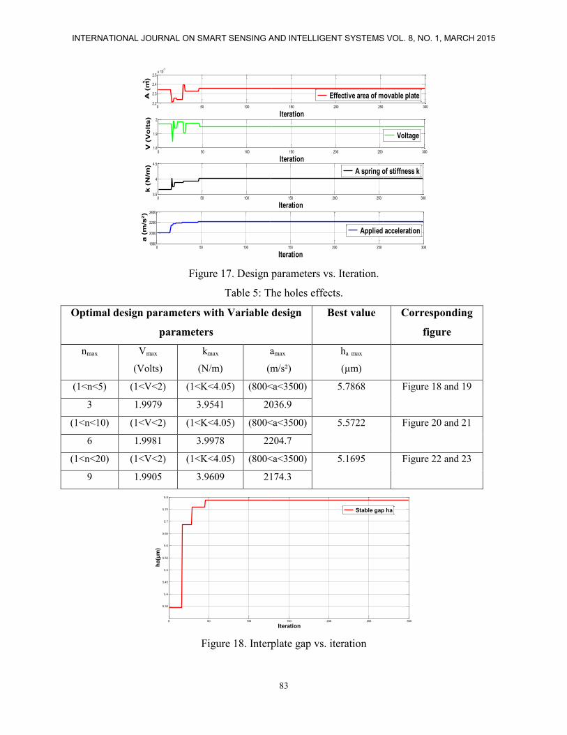
Figures 18 to 23 show the effect of number of holes on a stable gap (ha), when the number of
holes increase the value of a stable gap (ha) decrease for example in figure 18 and 19, when n=3
ha= 5.7868µm, in figure 20 and 21, n=6 and ha= 5.5722µm, in figure 22 and 23, when n= 9,
ha=5.1695µm.
Page 16
Souad Oukil, Abdelmadjid Boudjemai and Nabil Boughanmi, L-SHAPED CANTILEVER PARALLEL – PLATE MEMS ACCELEROMETER DESIGN PARAMETERS USING A GRAVITATIONAL SEARCH ALGORITHM
80
To analyze the effects of the number of the holes on the capacitance and pull-in voltage of a
parallel plate MEMS Accelerometer, numerical analysis holes effects are given.
The perforated plate leads to a reduction in mass per unit length of the structure by >20% as
compared to the solid structures. The holes also lead to a change in the area moment of inertia.
Therefore, since the natural frequency ωn of the structure is a function of mass and the geometry
(area moment of inertia and length), the presence of perforations directly leads to a change in the
natural frequency.
We noticed that the capacitance caused by the number of holes will be decreased and its quotient
in the total capacitance will be decreased. If the gap between the plates, ha, is given, the deviation
of the capacitance and the pull-in voltage will be increased as the length and width of the hole
increases.
This must be considered when researchers design tunable capacitors; otherwise the pull-in
voltage in fact will exceed the designed pull-in voltage, which will result in the failure or
breakage of the fabricated of a parallel plate MEMS Accelerometer.
Table 3: Parameters setting for GSA.
GSA parameters Value
Dimension of problem 05
Number of agents 150
Max-iteration. 300
Velocity clock
Acceleration. gateway node flag
Mass. Ma=Mp=Mi=M time master node flag
Position of agents. for internal clock
synchronization
Distance between agents in search
space.
for external clock
synchronization
Page 17
INTERNATIONAL JOURNAL ON SMART SENSING AND INTELLIGENT SYSTEMS VOL. 8, NO. 1, MARCH 2015
81
Table 4: Parameters design effects.
Optimal design parameters with Variable design
parameters
Best
value
Corresponding
figures
Amax
(m²)
Vmax
(Volts)
kmax
(N/m)
amax
(m/s²)
hamax
(µm)
2.10-7
<A<4.10-7
(1<V<2) (1<K<4) (800<a<3500) 2.3389 Figure 12 and 13
3.977.10-7
1.9977 3.8064 2069.6
2.10-7
<A<3.10-7
(1<V<2) (1<K<4) (800<a<4000) 2.1044 Figure 14 and 15
2.9983.10-7
1.9669 3.7995 2998.3
2.10-7
<A<2.4.10-7
(1<V<2) (1<K<4.05) (800<a<3500) 2.0097 Figure 16 and 17
2.3558.10-7
1.9513 4.0301 2215.5
Figure 12. Interplate gap vs. iteration
Figure 13. Design parameters vs. Iteration.
0 50 100 150 200 250 3002.25
2.26
2.27
2.28
2.29
2.3
2.31
2.32
2.33
2.34
Iteration
ha (
µm
)
Stable gap ha
0 50 100 150 200 250 3003.6
3.8
4x 10
-7
Iteration
A (
m)
Effective area of movable plate
0 50 100 150 200 250 3001.8
1.9
2
Iteration
V (
Vo
lts)
Voltage
0 50 100 150 200 250 3003.8
3.85
3.9
3.95
Iteration
k (
N/m
)
A spring of stiffness k
0 50 100 150 200 250 3002000
2100
2200
2300
Iteration
a (
m/s
²)
Applied acceleration
2
Page 18
Souad Oukil, Abdelmadjid Boudjemai and Nabil Boughanmi, L-SHAPED CANTILEVER PARALLEL – PLATE MEMS ACCELEROMETER DESIGN PARAMETERS USING A GRAVITATIONAL SEARCH ALGORITHM
82
Figure 14. Interplate gap vs. iteration
Figure 15. Design parameters vs. Iteration.
Figure 16. Interplate gap vs. iteration
0 50 100 150 200 250 3001.8
1.85
1.9
1.95
2
2.05
2.1
2.15
Iteration
ha (
µm
)
Stable gap ha
0 50 100 150 200 250 3002
2.5
3x 10
-7
Iteration
A (
m)
Effective area of movable plate
0 50 100 150 200 250 3001.7
1.8
1.9
2
Iteration
V (
Vo
lts)
Voltage
0 50 100 150 200 250 3003.6
3.8
4
Iteration
k (
N/m
)
A spring of stiffness k
0 50 100 150 200 250 3002000
3000
4000
Iteration
a (
m/s
²)
Applied acceleration
2
0 50 100 150 200 250 3001.88
1.9
1.92
1.94
1.96
1.98
2
2.02
Iteration
ha (
µm
)
Stable gap ha
Page 19
INTERNATIONAL JOURNAL ON SMART SENSING AND INTELLIGENT SYSTEMS VOL. 8, NO. 1, MARCH 2015
83
Figure 17. Design parameters vs. Iteration.
Table 5: The holes effects.
Optimal design parameters with Variable design
parameters
Best value Corresponding
figure
nmax Vmax
(Volts)
kmax
(N/m)
amax
(m/s²)
ha max
(µm)
(1<n<5) (1<V<2) (1<K<4.05) (800<a<3500) 5.7868 Figure 18 and 19
3 1.9979 3.9541 2036.9
(1<n<10) (1<V<2) (1<K<4.05) (800<a<3500) 5.5722 Figure 20 and 21
6 1.9981 3.9978 2204.7
(1<n<20) (1<V<2) (1<K<4.05) (800<a<3500) 5.1695 Figure 22 and 23
9 1.9905 3.9609 2174.3
Figure 18. Interplate gap vs. iteration
0 50 100 150 200 250 3002.2
2.3
2.4
2.5x 10
-7
Iteration
A (
m)
Effective area of movable plate
0 50 100 150 200 250 3001.8
1.9
2
Iteration
V (
Vo
lts)
Voltage
0 50 100 150 200 250 3003.5
4
4.5
Iteration
k (
N/m
)
A spring of stiffness k
0 50 100 150 200 250 3001800
2000
2200
2400
Iteration
a (
m/s
²)
Applied acceleration
2
0 50 100 150 200 250 300
5.35
5.4
5.45
5.5
5.55
5.6
5.65
5.7
5.75
5.8
Iteration
ha(µ
m)
Stable gap ha
Page 20
Souad Oukil, Abdelmadjid Boudjemai and Nabil Boughanmi, L-SHAPED CANTILEVER PARALLEL – PLATE MEMS ACCELEROMETER DESIGN PARAMETERS USING A GRAVITATIONAL SEARCH ALGORITHM
84
Figure 19. Design parameters vs. Iteration.
Figure 20. Interplate gap vs. iteration
Figure 21. Design parameters vs. Iteration.
0 50 100 150 200 250 3001
2
3
Iteration
n
holes number
0 50 100 150 200 250 3001.8
1.9
2
Iteration
V (
Vo
lts)
Voltage
0 50 100 150 200 250 3003.5
4
4.5
Iteration k
(N
/m)
A spring of stiffness k
0 50 100 150 200 250 3001500
2000
2500
3000
Iteration
a (
m/s
²)
Applied acceleration
0 50 100 150 200 250 3005.35
5.4
5.45
5.5
5.55
5.6
Iteration
ha (
µm
)
Stable gap ha
0 50 100 150 200 250 3000
2
4
6
Iteration
n
holes number
0 50 100 150 200 250 3001.9
1.95
2
Iteration
V (
Vo
lts)
Voltage
0 50 100 150 200 250 3003.5
4
4.5
Iteration
k (
N/m
)
A spring of stiffness k
0 50 100 150 200 250 3001000
1500
2000
2500
Iteration
a (
m/s
²)
Applied acceleration
Page 21
INTERNATIONAL JOURNAL ON SMART SENSING AND INTELLIGENT SYSTEMS VOL. 8, NO. 1, MARCH 2015
85
Figure 22. Interplate gap vs. iteration.
Figure 23. Design parameters vs. Iteration.
V. FINITE ELEMENT SIMULATIONS AND MODAL ANALYSIS OF L-SHAPED
CANTILEVER PARALLEL - PLATE MEMS ACCELEROMETERS
A modal analysis was conducted to calculate the fundamental frequencies and modal shapes of
the accelerometer. The boundary condition in the FEM simulation concerns the one edge of the
short side which is constrained (displacement of x, y and z are zero, and rotation of x, y and z are
zero) in the cantilevered L shaped MEMS. The finite element model (FEM) of a MEMS
accelerometer is given by figure 24.
Figure 25 shows the frequencies modes of MEMS accelerometer obtained using Msc.
Patran/Nastran software. The results gives the structure modal forms, and which makes it
possible to see where are made the most deformations and which elements.
The colored fringes give the amplitude of the displacement vector describing the shape of each
mode. The black color corresponds to null displacement and the red one presents the maximum
amplitude.
0 50 100 150 200 250 3004.85
4.9
4.95
5
5.05
5.1
5.15
5.2
Iteration
ha (
µm
)
Stable gap ha
0 50 100 150 200 250 300
6
8
10
Iteration
n
holes number
0 50 100 150 200 250 3001.8
1.9
2
Iteration
V (
Vo
lts)
Voltage
0 50 100 150 200 250 3003
3.5
4
4.5
Iteration
k (
N/m
)
A spring of stiffness k
0 50 100 150 200 250 3001500
2000
2500
Iteration
a (
m/s
²)
Applied acceleration
Page 22
Souad Oukil, Abdelmadjid Boudjemai and Nabil Boughanmi, L-SHAPED CANTILEVER PARALLEL – PLATE MEMS ACCELEROMETER DESIGN PARAMETERS USING A GRAVITATIONAL SEARCH ALGORITHM
86
Figure 25 shows the displacement of the MEMS accelerometer in Z direction, the maximum is
about 2.003µm. The lowest frequency was in 1st mode (1061.6Hz), which gives the better the
vibration direction. The frequency was increasing with each subsequent mode of vibration.
The translation in-plane modes, have a frequency around 6655.4Hz. The resulting modes from
FEM simulations are the lowest frequency modes in the design and turns out to be at 1061.6Hz.
The two following modes occur around 2111Hz and correspond to Out-of plane rotation. The
rotation results in a tension (or compression) common to the four L-shaped beam. For small-
displacements, the out-of-plane translation does not introduce any axial force in the L-shaped
beam. The other modes are at frequencies high enough to guarantee low sensitivity.
Figure 24. MEMS acceleromter FEM model.
Mode 1, f1=1061.6Hz, Displacement field in Z direction. Mode 2, f2=2111Hz, Out-of plane rotation around the y-axis.
Mode 3, f3=2111Hz, Out-of plane rotation around the x-axis. Mode 4, f4=6655.4Hz, In-plane translation in y- direction
Page 23
INTERNATIONAL JOURNAL ON SMART SENSING AND INTELLIGENT SYSTEMS VOL. 8, NO. 1, MARCH 2015
87
Mode 5, f5=6655.9Hz, In-plane translation in x-direction Mode 6, f6=15382Hz, In-plane rotation
Mode 7, f7=39529Hz Mode 8, f8=49429Hz, mechanical mode of the spring.
Mode 9, f9=50286Hz, mechanical mode of the spring. Mode 10, f10=50287Hz, mechanical mode of the spring
Figure 25. Various shape modes of the cantilevered L shaped MEMS.
VI. CONCLUSIONS
In this paper, we have proposed a system to perform the optimization of the design parameters in
the L-shaped MEMS accelerometer. For this, we have employed a Gravitational Search
optimization algorithm which provides an efficient optimization technique. The result shows that
this method has delivered better results in terms of the fitness values. The simulation results also
show that the intensity of the springs which is the weakest part in the accelerometer meets the
Page 24
Souad Oukil, Abdelmadjid Boudjemai and Nabil Boughanmi, L-SHAPED CANTILEVER PARALLEL – PLATE MEMS ACCELEROMETER DESIGN PARAMETERS USING A GRAVITATIONAL SEARCH ALGORITHM
88
material intensity under the applied external accelerations in all directions. A modal analysis
was used to extract the fundamental frequencies and modal shapes of the design as a reference for
the range of operation of the device. The lowest natural frequency of the device is about 1061.6
Hz.
REFERENCES
[1] A. Zia, M.A.S Rahman, S.C. Mukhopadhyay, I. H. Al-Bahadly, P. L. Yu, C. Gooneratne, J. Kosel
and T.S. Liao, MEMS Based Impedimetric Sensing of Phthalates, Proceedings of IEEE I2MTC
2013 conference, IEEE Catalog number CFP13IMT-CDR, ISBN 978-1-4673-4622-1, May 6-9,
2013, Minneapolis, USA, pp. 855-860.
[2] A. I. Zia, S. C. Mukhopadhyay, P.L. Yu, I.H. Al-Bahadly, C. P. Gooneratne, J. Kosel, “Post
Annealing Performance Evaluation of Printable Interdigital Capacitive Sensors by Principal
Component Analysis”, IEEE Sensors Journal, 2014, http://dx.doi.org/10.1109/JSEN.2014.2355224.
[3] A. Sundaram, M. Maddela, R. Ramadoss, and L. Feldner, MEMS-Based electronically steerable
antenna array fabricated using PCB technology, Microelectromechanical Systems, Journal of, vol.
17, no. 2, pp. 356-362, Apr. 2008.
[4] C-H. Han, D-H. Choi, and J-B. Yoon, Parallel-plate MEMS variable capacitor with superior
linearity and large tuning ratio using a levering structure," Microelectromechanical Systems,
Journal of, vol. 20, no. 6, pp. 1345-1354, Dec. 2011.
[5] M. Kraft, C. Lewis, T. Hesketh, and S. Szymkowiak, A novel micromachined accelerometer
capacitive interface, Sensors and Actuators A: Physical, vol. 68, no. 13, pp. 466-473, Jun. 1998.
[6] Y. Fenglin, G. Shiqiao, Z. Jie, L. Haipeng, N. Shaohua, J. Lei , The vibration and measurement of
driving mode of the two-stage decoupled micro-machined gyroscope, Int. J. Smart Sens. Intell.
Syst. 6 (2013) 1599-1616.
[7] N. El-Bendary, Q. Tan, F. C. Pivot, A. Lam, Fall detection and prevention for the elderly: a review
of trends and challenges, Int. J. Smart Sens. Intell. Syst. 6 (2013) 1230-1266.
[8] S. J. Kim, G. Flowers, C. Chen, and R. Dean, \Active vibration control and isolation for micro-
machined devices," in ASME 2008 Conference on Smart Materials, Adaptive Structures and
Intelligent Systems, Jan. 2008, pp. 657-664.
[9] Ding W., (2013), MEMS pressure sensor, Market & technology report, Yole Développement.
[10] Jeff Perkins, MEMS Everywhere: Sensing the world around you, and more Semicon West, Yole
Developpement, 2012 available at http://www.semiconwest.org/sites/ semiconwest.org/files/docs/.
[11] L. M. Roylance and J. B. Angell, A Batch-Fabricated Silicon Accelerometer, IEEE Trans. Elec.
Dev., ED-26, 1911 (1979).
[12] Trolier Mckinstry and P. Muralt, Thin film piezoelectrics for MEMS, J. Electroceramics, vol. 12,
no. 1-2, pp. 7–17, 2004.
[13] T. Berther, G.H. Gautschi, J. Kubler, Capacitive accelerometers for static and low-frequency
measurements, Sound and Vibration 30 (6)(1996) 28-30.
[14] H. Chen, S. Shen, M. Bao, Over-range capacity of a piezoresistive micro accelerometer, Sens.
Actuators 58 (3) (1997) 197-201.
[15] G. H. Gautschi, Piezoelectric Sensorics. New York: Springer, 2002.
[16] Biter Boga, et al., Modeling of a capacitive Σ-Δ mems accelerometer system Including the noise
components and Verification with test results, pp. 821 – 824, doi
10.1109/MEMSYS.2009.4805509-2009 ©IEEE.
[17] Yoshida, K.; Matsumoto, Y.; Ishida, M.; Okada, K. High-Sensitive Three Axis SOI Capacitive
Accelerometer Using Dicing Method. Proceedings of Technical Digest of the 16th Sensor
Page 25
INTERNATIONAL JOURNAL ON SMART SENSING AND INTELLIGENT SYSTEMS VOL. 8, NO. 1, MARCH 2015
89
Symposium, Toyohashi, Japan, 2–3 June 1998; pp. 25–28.
[18] Vincas Benevicius et al., Identification of Capacitive MEMS Accelerometer Structure Parameters
for Human Body Dynamics Measurements, Sensors 2013, 13, 11184-11195;
doi:10.3390/s130911184
[19] D.Ozevin et al., Resonant capacitive MEMS acoustic emission transducers, Smart Mater. Struct. 15
(2006) 1863–1871, doi:10.1088/0964-1726/15/6/041.
[20] H. Helvajian, ed, “Microengineering Aerospace Systems”, The Aerospace Press, 1999
[21] S. Cass, “MEMS in Space”, IEEE Spectrum, p.56, July 2001
[22] Robert Osiander, M. Ann Garrison Darrin, John L. Champion (Editors), “MEMS and
Microstructures in Aerospace Applications”, CRC (2005) 400 pages, Chapter 11, Micropropulsion
technologies, J. Schein, pp. 229.
[23] Hoon Sohn et al., A Review of Structural Health Monitoring Literature: 1996–2001, Los Alamos
National Laboratory Report, LA-13976-MS, 2004.
[24] T. Paul, J. Singh, M.M. Nayak, K. Rajanna, M.S. Kumar, Design and optimization of bulk
micromachinaded accelerometer for space applications, Int. J. Smart Sens. Intell. Syst. 1 (2008)
1019-1030.
[25] J.S. Botero V, W. Hernández, E. Fernández, Orientation of a triaxial accelerometer using a
homogeneous transformation matrix and kalman filters, Int. J. Smart Sens. Intell. Syst. 7 (2014)
1631-1646.
[26] R.R. Craig, A.J. Kurdila, Fundamentals of Structural Dynamics [M], Wiley.com, 2006.
[27] Ki Bang Lee, Principles of Microelectromechanical Systems, John Wiley & Sons, Inc., 2011.
[28] Esmat Rashedi, Hossein Nezamabadi, Saeid Saryazdi. GSA: A Gravitational Search Algorithm.
Department of Electrical Engineering, Shahid Bahonar University of Kerman, P.O. Box 76169-133,
Kerman, Iran. Information Sciences 179 (2009) 2232–2248.
[29] M. Ghalambaz, A.R. Noghrehabadi, M.A. Behrang, E. Assareh, A. Ghanbarzadeh, N.Hedayat, A
Hybrid Neural Network and Gravitational Search Algorithm (HNNGSA) Method to Solve well
known Wessinger's Equation, World Academy of Science, Engineering and Technology 73 2011.
[30] Serhat Duman, Yusuf Sonmez, Yusuf Sonmez, Application of Gravitational Search Algorithm for
Optimal Reactive Power Dispatch Problem, pp. 519 – 523, 987-1-61284-922-5/11/$26.00©2011
IEEE.
[31] Mohammad Khajehzadeh and Mahdiyeh Eslami, Gravitational search algorithm for optimization of
retaining structures, Indian Journal of Science and Technology, pp.1821-1827, Vol. 5 No. 1 (Jan
2012) ISSN: 0974- 6846.
[32] A.Chatterjee and G. K. Mahanti, Comparative performance of gravitational search algorithm and
modified particle swarm optimization algorithm for synthesis of thinned scanned concentric ring
array antenna, Progress in Electromagnetics Research B, Vol. 25, 331-348, 2010.