NIET JOURNAL oFENGINEERING &TECHNOLOGY Winter 2011 co N co L{) I (J) N N N Z (j) (j) STUDY AND SIMULATION OF THE UNIFIED POWER FLOW CONTROLLER (UPFC) IN POWER SYSTEM Ragini Malviya' Abstract The main objectives of Flexible AC Transmission Systems (FACTS) devices are to increase the transmission capacity of lines and to control the power flow over designated transmission system. FACTS devices can perform all objectives of reactive power control and voltage control required for transmission and lines. Several schemes of flexible AC transmission systems FACTSare in use today. One of the most important FACTS devices is the Unified Power Flow Controller (UPFC),which is used for series voltage injection in desired phase as shown in Fig 1. The UPFC is a combination of a static Compensator (STATCOM) and a static synchronous series compensator (SSSC), which are coupled via a common DC link. 'Department of Electrical Engineering NJET, Gr. Noida Introduction The UPFC is a device, which can control simultaneously all the three parameters of line power flow which are line impedance, voltage and phase angle. The UPFC improves terminal voltage regulation, series capacitor compensation and transmission angle regulation. This paper explains the control scheme and comprehensive analysis of a unified power flow controller (UPFC). A MATlAS program using SIMULI N K/SI M POWER SYSTEMS toolboxes is developed for simulation of UPFC. This developed simulation technique is found to be very effective and it enables us to study and investigate how the UPFC can affect the transmission system using the series voltage and shunt current injection. It is possible to demonstrate with this simulation that the UPFC can improve the system characteristics and give the best transient and dynamic stability. It also improves the power factor. Some cases are investigated and studied such as the application of the UPFC to control voltage and power flow. These cases are tested for a power system with varying active and reactive power requirements of load. In all cases, the performance of the system was analyzed, tested and studied to indicate voltages, currents and power performance and shown to be satisfactory. Unified Power Flow Controller (UPFC) is a generalized Synchronous Voltage Source(SVS), represented at the fundamental (power system) frequency by voltage phasor Vpq as shown in fig 2 with controllable """"~ •..••
Transcript
NIETJOURNALoFENGINEERING&TECHNOLOGY
Winter 2011coNcoL{)
I(J)
NNNZ(j)(j)STUDY AND SIMULATION OF THE
UNIFIED POWER FLOW CONTROLLER(UPFC) IN POWER SYSTEM
Ragini Malviya'
AbstractThe main objectives of Flexible AC TransmissionSystems (FACTS) devices are to increase thetransmission capacity of lines and to control thepowerflow over designated transmission system. FACTSdevices can perform all objectives of reactive powercontrol and voltage control required for transmissionand lines. Several schemes of flexible ACtransmission systems FACTSare in use today. One ofthe most important FACTS devices is the UnifiedPowerFlow Controller (UPFC),which is used for seriesvoltage injection in desired phase as shown in Fig 1.The UPFC is a combination of a static Compensator(STATCOM) and a static synchronous seriescompensator (SSSC), which are coupled via acommon DC link.
'Department of Electrical EngineeringNJET, Gr. Noida
Introduction
The UPFC is a device, which can controlsimultaneously all the three parameters of linepower flow which are line impedance, voltageand phase angle. The UPFC improves terminalvoltage regulation, series capacitorcompensation and transmission angleregulation. This paper explains the controlscheme and comprehensive analysis of aunified power flow controller (UPFC). A MATlASprogram using SIMULI N K/SI M POWERSYSTEMS toolboxes is developed for simulationof UPFC. This developed simulation technique isfound to be very effective and it enables us tostudy and investigate how the UPFC can affectthe transmission system using the series voltageand shunt current injection. It is possible todemonstrate with this simulation that the UPFCcan improve the system characteristics and givethe best transient and dynamic stability. It alsoimproves the power factor. Some cases areinvestigated and studied such as the applicationof the UPFC to control voltage and power flow.These cases are tested for a power system withvarying active and reactive power requirementsof load. In all cases, the performance of thesystem was analyzed, tested and studied toindicate voltages, currents and powerperformance and shown to be satisfactory.
Unified Power Flow Controller (UPFC) is ageneralized Synchronous VoltageSource(SVS), represented at the fundamental(power system) frequency by voltage phasorVpq as shown in fig 2 with controllable """"~ •..••
Winter 2011
TransmissionLine vV"VN"~~~----~~~----~~~~~~~
I I Supply transformer /' Series transformerllJ Convertor 1 Convertor 2 ~
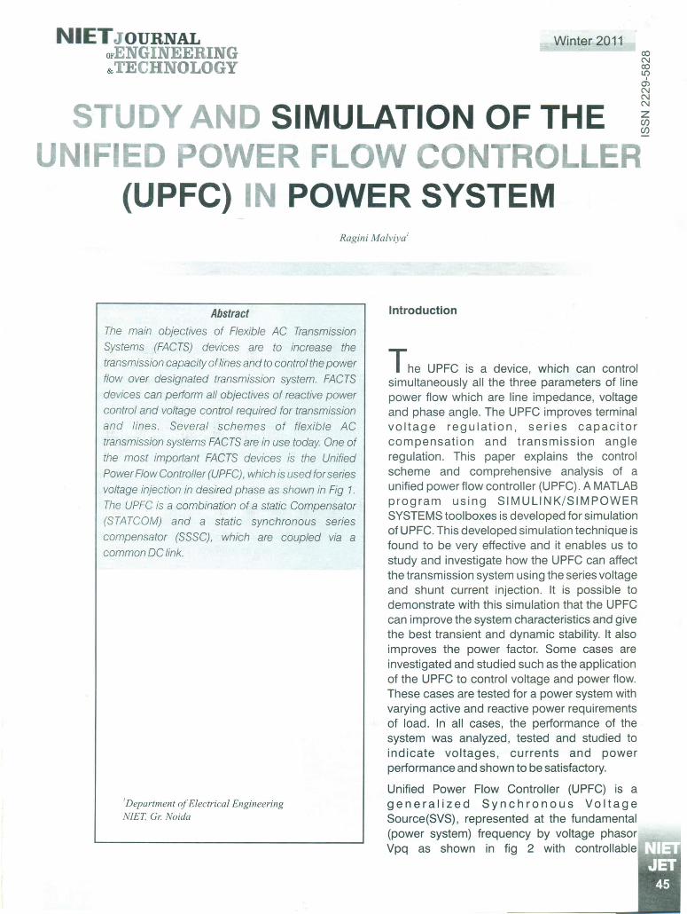
at the DC link [1]. The reactivepower exchanged at the AC ofconverter 2 terminal isgenerated internally by theinverter [2]. Converter 1supplies or absorbs the realpower demanded by converter2 at the common DC link. ThisDC link power is convertedback to AC and coupled to thetransmission line via a shuntconnected transformer.Converter 1 can also generateor absorb controllable reactivepower and can provideindependent shunt reactivecompensation for the liner(voltage control). Converter 2controls the magnitude and the
angle of Vpq which controls voltage at thereceiving end and the power flow. The basicfunctions of the UPFC are terminal voltageregulation, series capacitor compensation andtransmission angle regulation.
The UPFC is an extremely powerful and versatiledevice for power flow control. The capability ofchanging all transmission parameters affectingpower flow simultaneously by UPFC andequation pertaining to Real f(P) and Reactive(Qr) are as follows:
m ~.~~ .• • II. ; )~ ,r .~ ~~ ,r );
-~ ,~~
I~ ac-~-
;Ir •~ ;Ir •~ ,I. ,III. I ,1. • III. • ,1. .11I.
ured j I r I Iles CONTROL Eeter
MeasVariabParamSettingsFig 1./mp/ementation of UPFC by two back-to-back voltagesource convertors
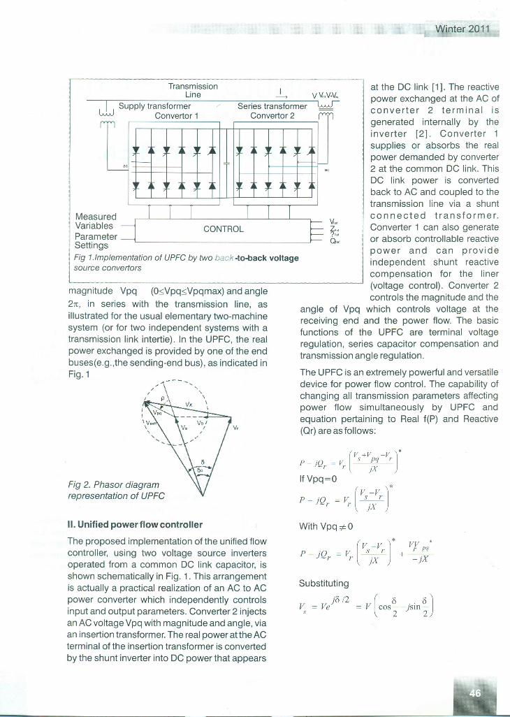
magnitude Vpq (osvpqsvpqmax; and angle2n, in series with the transmission line, asillustrated for the usual elementary two-machinesystem (or for two independent systems with atransmission link intertie). In the UPFC, the realpower exchanged is provided by one of the endbuses(e.g.,the sending-end bus), as indicated inFig. 1 --- ..•••..
v.
Fig 2. Phasor diagramrepresentation of UPFC
II. Unified power flow controller
The proposed implementation of the unified flowcontroller, using two voltage source invertersoperated from a common DC link capacitor, isshown schematically in Fig. 1. This arrangementis actually a practical realization of an AC to ACpower converter which independently controlsinput and output parameters. Converter 2 injectsan AC voltage Vpq with magnitude and angle, viaan insertion transformer. The real power at the ACterminal of the insertion transformer is convertedby the shunt inverter into DC power that appears
r : "Q = v (Vs+Vpq-Vrj*) r r l jX
PlfVPqQ=O__v (Vs-VrJ*- j r r jX
With Vpq *0
( J* •v -v vr pq
P-j"Q =V .s.:»;+-xr r jX - j
Substituting
j8/2 (8"" 8)V, = Ve = V COS"2-1S111"2
NIETJOURNALoFENGINEERING&TECHNOLOGY
v - )'6 12 V ( '6 .. '6)r = Ve = cos2- 1SIn2
and
v = VfXI fXI
)('6/2Xp) {('6 h (8 )}= Vpq cas 2 +P )' )sin "2+P
and
where
andv2
Q (8)=--(1-00;8)or X
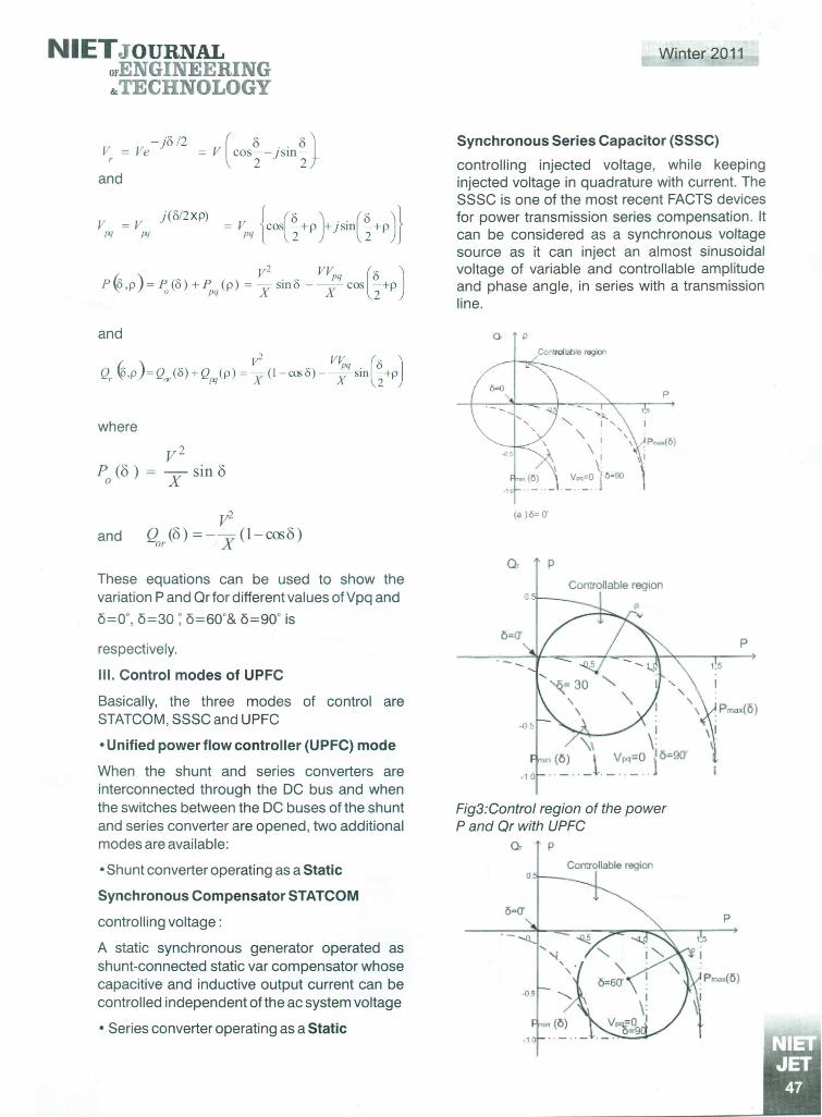
These equations can be used to show thevariation P and Qr for different values of Vpq and0=0·, 0=3070=60·& 0=90· is
respectively.
III. Control modes of UPFC
Basically, the three modes of control areSTATCOM, SSSC and UPFC
• Unified power flow controller (UPFC) mode
When the shunt and series converters areinterconnected through the DC bus and whenthe switches between the DC buses of the shuntand series converter are opened, two additionalmodes are available:
• Shunt converter operating as a Static
Synchronous Compensator STATCOM
controlling voltaqe :
A static synchronous generator operated asshunt-connected static var compensator whosecapacitive and inductive output current can becontrolled independent ofthe ac system voltage
• Series converter operating as a Static
Winter 2011
Synchronous Series Capacitor (SSSC)
controlling injected voltage, while keepinginjected voltage in quadrature with current. TheSSSC is one of the most recent FACTS devicesfor power transmission series compensation. Itcan be considered as a synchronous voltagesource as it can inject an almost sinusoidalvoltage of variable and controllable amplitudeand phase angle, in series with a transmissionline.
Q p
Controllable region
p
1.5
.P"",(5)
I
(a)6=0"
Q. PControllable region
Fig3:Control region of the powerP and Or with UPFC
A UPFC is used to control the power flow in a 500kV /230 kV transmission system as shown byFig.4. The system, connected in a loopconfiguration, consists essentially of five buses(81 to 85) interconnected through threetransmission lines (L1, L2, L3) and two 500kV/230 kV transformer banks Tr1 and Tr2. Twopower plants located on the 230 kV systemgenerate a total of 1500 MW which is transmittedto a 500 kV, 15000 MVA equivalent and to a 200MW load connected at bus 83. Each plant modelincludes a speed regulator, an excitation systemas well as a power system stabilizer (PSS). Innormal operation, most of the 1200 MWgeneration capacity of power plant #2 isexported to the 500 kV equivalent through two400 MVA transformers connected betweenbuses 84 and 85. For this demo we areconsidering a contingency case where only twotransformers out of three are available (Tr2=2*400 MVA = 800 MVA). The load flow showsthat most of the power generated by plant #2 istransmitted through the 800 MVA transformer
loooMWtooo uw
230 kV
196.6 I689.1 I
681 I796 Ivpos. seq. 81 82 B3 B4 as
12/1 IVPQMeasurements
P B1 82 B3 B4 as (MW)
a 818283 B4 B5 (Mvar)l..__ J"-"-'-::::"::::'==:.:::L---:v'PQ LinesActive Powers (MW)
BI B2B3B485
UPFC (Phasor Model)Control of Power Flow using a Unified Power Flow Controller (UPFC)
info
NIETJOURNALoFENGINEERING&TECHNOLOGY
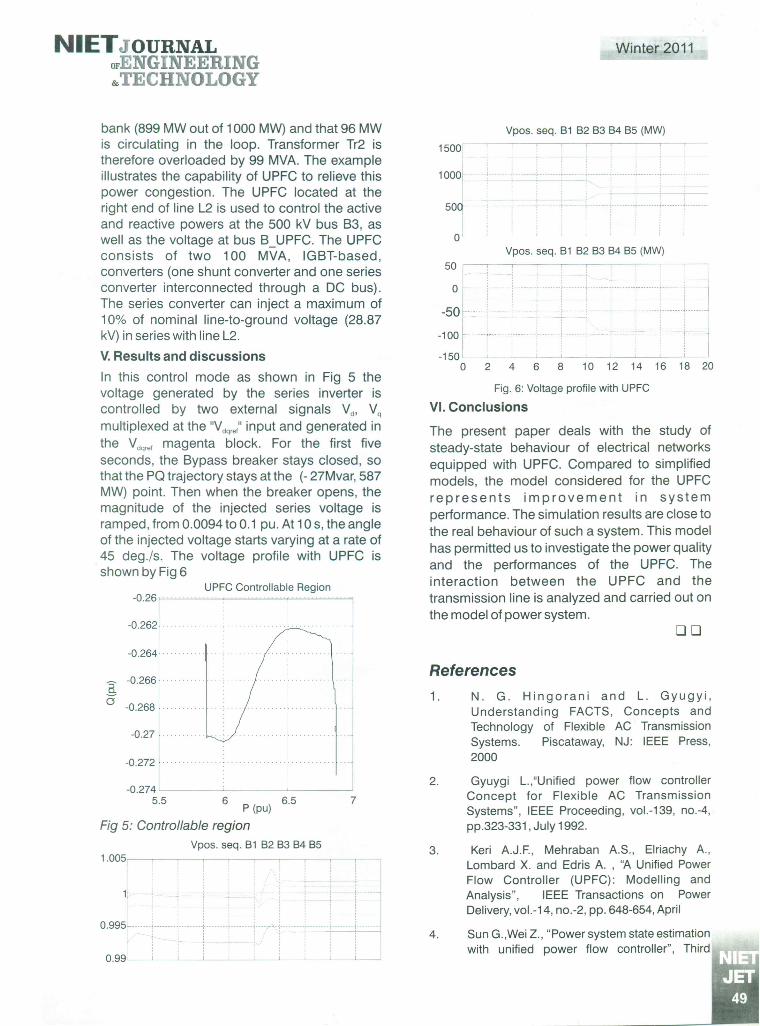
bank (899 MW out of 1000 MW) and that 96 MWis circulating in the loop. Transformer Tr2 istherefore overloaded by 99 MVA. The exampleillustrates the capability of UPFC to relieve thispower congestion. The UPFC located at theright end of line L2 is used to control the activeand reactive powers at the 500 kV bus B3, aswell as the voltage at bus B_UPFC. The UPFCconsists of two 100 MVA, IGBT-based,converters (one shunt converter and one seriesconverter interconnected through a DC bus).The series converter can inject a maximum of10% of nominal line-to-ground voltage (28.87kV) in series with line L2.
V. Results and discussionsIn this control mode as shown in Fig 5 thevoltage generated by the series inverter iscontrolled by two external signals Vd, Vqmultiplexed at the "Vdqrei'input and generated inthe Vdqrefmagenta block. For the first fiveseconds, the Bypass breaker stays closed, sothat the PO trajectory stays at the (- 27Mvar, 587MW) point. Then when the breaker opens, themagnitude of the injected series voltage isramped, from 0.0094 to 0.1 pu. At 10 s, the angleof the injected voltage starts varying at a rate of45 deg./s. The voltage profile with UPFC isshown by Fig 6
The present paper deals with the study ofsteady-state behaviour of electrical networksequipped with UPFC. Compared to simplifiedmodels, the model considered for the UPFCrepresents improvement in systemperformance. The simulation results are close tothe real behaviour of such a system. This modelhas permitted us to investigate the power qualityand the performances of the UPFC. Theinteraction between the UPFC and thetransmission line is analyzed and carried out onthe model of power system.
DO
References1. N. G. Hingorani and L. Gyugyi,
Understanding FACTS, Concepts andTechnology of Flexible AC TransmissionSystems. Piscataway, NJ: IEEE Press,2000Gyuygi L.,"Unified power flow controller
Concept for Flexible AC TransmissionSystems", IEEE Proceeding, vol.-139, no.-4,pp.323-331, July 1992.
Keri AJ.F., Mehraban AS., Elriachy A.,Lombard X. and Edris A , "A Unified PowerFlow Controller (UPFC): Modelling andAnalysis", IEEE Transactions on PowerDelivery, vol.-14, no.-2, pp. 648-654, April
Sun G.,Wei Z., "Power system state estimationwith unified power flow controller", Third
2.
3.
4.
5.
International Conference on Electric UtilityDeregulation and Restructuring and PowerTechnologies, pp.775 -778, April 2008.
Schoder K., Hasanovic A., Feliachi A. and AzraH., "Load-Flow and Dynamic Model of UPFCwithin the Power System Toolbox (PST)", 43rdIEEE Midwest Symposium on Circuits andSystems, vol. 2, pp. 634-637, August 2002,
Guo J., Crow M.L., Sarangapani J., "AnImproved UPFC Control for OscillationDamping", IEEE Transactions on PowerSystems, vol.-24, no.-1, pp.288-296, Feb.2009.
6.
7. Zarghami M., Crow M.L.,Sarangapani J.,Atcitty S., "A Novel Approach to InterareaOscillation Damping by Unified Power FlowControllers Utilizing Ultracapacitors", IEEETransactions on Power Systems, vol.-25, no.-1,ppA04-412, Feb 201 O.
Winter 2011
8. Papic I., Zunko P.and Povh 0, "Basic Control ofUnified Power Flow Controller", IEEETransactions on Power Systems, vol.-12, no.-4, pp.1734-1739, August 1997.
Mihalic R., Povh D. and Zunko P, "Improvementof Transient Stability using UPFC", IEEETransactions on power delivery, vol.-11, no.-1,pp. 485-492, August 1996.
Padiyar K.R. and Kulkarni A.M.,"ControlDesign and Simulation of UPFC", IEEETransactions on Power Delivery, vol.-13, nO.-4,pp. 1348-1354, Oct. 1998.
9.
10.
11. L. Gyugyi, "Dynamic compensation of actransmission lines by solid-state synchronousvoltage sources," IEEE Trans. Power Del., vol.9, no. 2, pp. 904-911, Apr. 1994.