BASIC PRINCIPLES OF SUBSEA PRODUCTION - FLOW ASSURANCE ISSUES
SEPARATOR
PLATFORM OR FLOATER
GAS
RISER BASE
FLOWLINES
SUPPLY LINES
DISTRIBUTECHEMICALS
TREE
2 - 100 km
SEA BED
1000 -
10000 m
OIL
WATER
50 -
2000 m
RISERPROCESS FACILITIES
FLOW ASSURANCE
1) HYDRAULICS - Is there enough energy in the flow to reach the processing host?
2) CORROSIVE COMPONENTS in the oil i.e.. H2S and CO2 - It can be corrected by chemical injection.
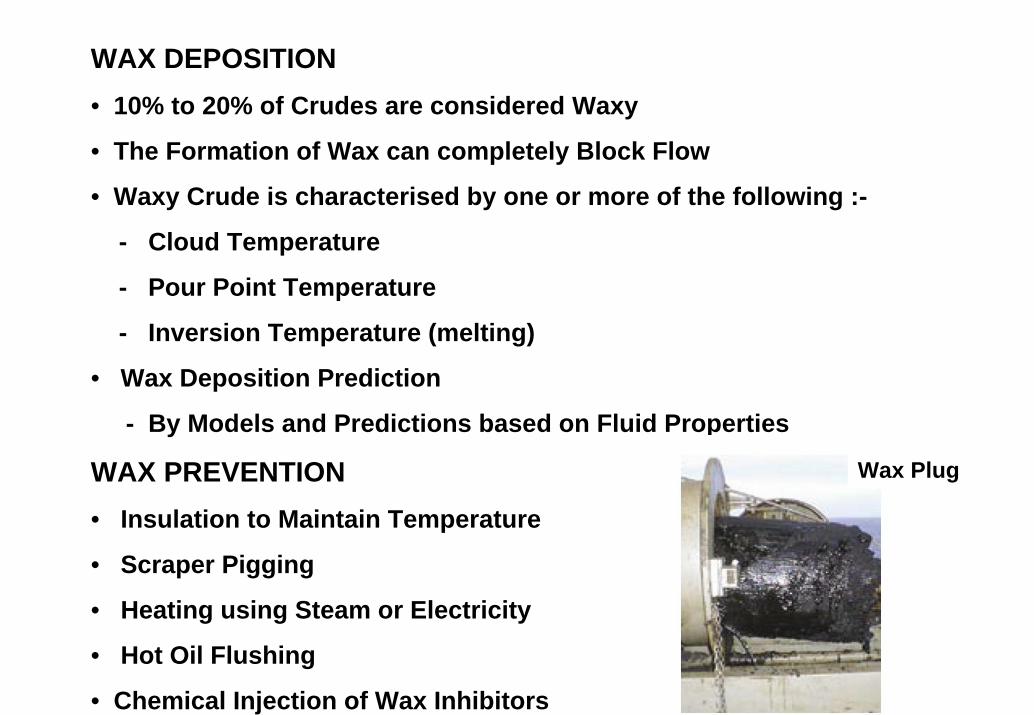
3) Is there any WAX in the oil that may block the lines on cooling.
4) Combinations of Gas and Water may form HYDRATES which block the line.
Flow Assurance Design Issues
FLOW ASSURANCE DESIGN
Paraffin/Asphaltenes
Gas Hydrates
Liquid Slugging
Scale
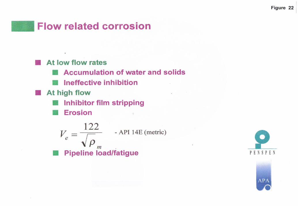
Corrosion
Sand/Erosion
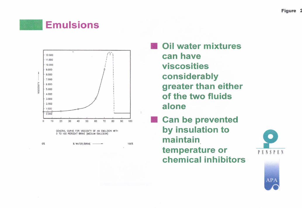
Emulsion/Foam
FLOW ASSURANCE
- H y d r a te s - F o rm a t io n o f ic e c ry s ta ls in c o rp a ra t in g m e th a n e a n d o th e rh y d ro c a rb o n s in lo w te m p e ra tu re s , h ig h p re s s u re , w e t s y s te m s p ro d u c in gg a s , c o n d e n s a te o r o il.
- W a x / A s p h a lte n e s - T h e d e p o s it io n o f s o lid s in s id e th e f lo w lin e s a n dr is e rs re d u c in g f lo w c a p a c ity a n d u lt im a te ly b lo c k in g th e lin e .
- S lu g g in g - T h e p h e n o m e n a c a u s e d b y th e in s ta b il it ie s o f th e g a s a n dliq u id in te r fa c e s a n d liq u id s w e e p -o u t b y g a s in e r t ia l e f fe c ts .
- C o r r o s io n - W e a r in g o f th e p ip e w o rk a n d f lo w lin e w a ll th ic k n e s s d u e toc h e m is try o f th e p ro d u c e d f lu id s .
- E m u ls io n s - O il a n d w a te r m ix tu re s a t a p p ro x im a te ly 4 0 to 6 0 % w a te r c u tth a t c a u s e e x c e s s iv e p re s s u re lo s s e s in th e w e lls o r th e S P S s y s te m .
- S c a lin g - S o lid s b u ild u p , e s p e c ia lly o n to th e w e ll b o re tu b in g d u e to th ec h e m is try o f th e p ro d u c e d w a te r .
- S a n d P r o d u c t io n - S a n d p ro d u c t io n f ro m th e re s e rv o ir c a u s in g b lo c k a g eo f s y s te m c o m p o n e n ts s u c h a s f lo w lin e s .
- E r o s io n - W e a r in g o f th e m a n ifo ld p ip e w o rk a n d th e f lo w lin e w a lls d u e tos o lid p a r t ic le s s u c h a s s a n d o r l iq u id s im p in g e m e n t p a s s in g a t h ig hv e lo c it ie s .
- C o ld P o in ts - M u lt ip le n o n in s u la te d d e v ic e s in th e s y s te m in c o n ta c t w ithth e s u r ro u n d in g c o ld w a te r a c t in g a s fa s t h e a t e x c h a n g e rs in p a r t ic u la rd u r in g w e ll s h u t d o w n a n d o th e r o p e ra t in g m o d e s .
The successful design and operation of a multiphase production system must consider design parameters and issues for the entire system, from the reservoir to the processing and export facilities. To assure that the entire system can be designed to operate successfully and economically, system designers must consider flow assurance fundamentals such as reservoir characteristics, production profiles, produced fluid chemistry, and environmental conditions as well as mechanical, operational, risk, and economic issues for all parts of the system.
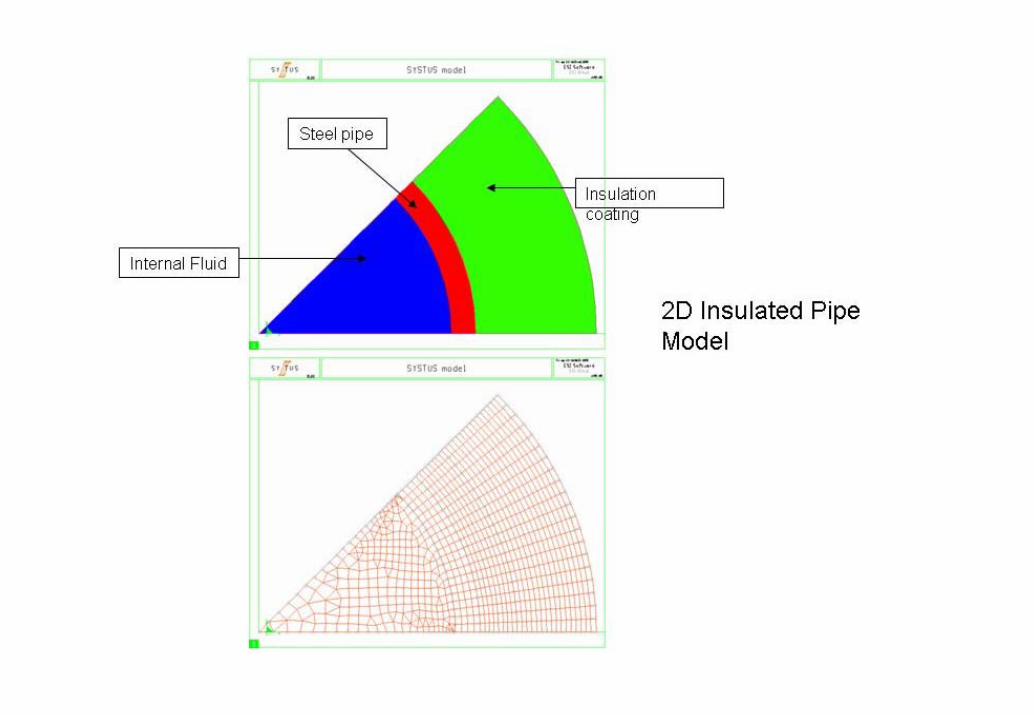
Important system parameters established as part of the design effort include tubing and flowline diameters, insulation (on wellbore tubing, trees, jumpers, manifolds, flowlines and risers), chemical injection requirements, flow blockage intervention provisions, host facility requirements, capital and operating costs, operating boundaries (e.g. maximum and minimum production rates), and risk mitigation. All production modes including startup, normal steady state operation, rate change, and shutdown must be considered throughout the system life-cycle.
Flow assurance encompasses the thermal-hydraulic design and assessment of multiphase production/transport systems as well as the prediction, prevention, and remediation of flow stoppages due to solids deposition (particularly due to hydrates and waxes). In all cases, flow assurance designs must consider the capabilities and requirements for all parts of the system throughout the entire production life ofthe system to reach a successful solution.
Operating philosophies, strategies, and procedures for successful system designs must be robust. They must be developed with system unknowns and uncertainties in mind and should be readily adapted to work with the system that is found to exist after production starts, even when that system is different from what was assumed during design (which often happens).
System Design is the synthesis of Flow Assurance and Operability features and attributes with those of all other aspects of the system. These include Reservoir, Completions, Subsea Hardware, Controls, Pipelines, Facilities, Production Operations, Transportation, Economics, and others. The successful flow assurance design will represent a system solution that best meets the needs of all groups.
Gas Lift
Topsides boundarycondition
Well ChokeJumper
Field Joints
Cover
FlowlineRiser
Pipework
TYPICAL FLOW HYDRAULICS MODEL Headers & Levels Diagram
• Predicted by Flow Map or by Computer based Information Schemes (OLGA / PLAC etc)
SEVERE SLUGGING
• Produced by Combinations of Segregated Flow and Terrain
• Particularly a problem in Risers
• Can be reduced by Discouraging Segregated Flow
• Predicted by Transient Flow Computer Models
A. SLUG FORMATION C. GAS PENETRATION
B. SLUG PRODUCTION D. GAS BLOW-DOWN
Hydrates are snow-like crystals which form at low temperatures and high pressures. They are a combination of water and methane (gas) molecules. Once formed they are quite stable.
If formed in pipelines they can cause a total blockage.
Their formation can be predicted from temperature –pressure data
GAS HYDRATES
Methane hydrate phase diagram. The horizontal axis shows temperature from -15 to 33 Celsius, the vertical axis shows pressure from 0 to 120,000 kilopascals (0 to 1,184 atmospheres). For example, at 4 Celsius hydrate forms above a pressure of about 50 atmospheres