Northwestern University Rod Ruoff Nanotechnology L12. Mechanics of Nanostructures: Mechanical Resonance Northwestern University Rod Ruoff Nanotechnology Outline 1. Theory 2. Mechanical Resonance Experiments 3. Ruoff group work SiO 2 nanowires Quartz Fibers Crystalline Boron Nanowires 4. Summary
Transcript
Northwestern University Rod Ruoff Nanotechnology
L12. Mechanics of Nanostructures: Mechanical
Resonance
Northwestern University Rod Ruoff Nanotechnology
Outline1. Theory
2. Mechanical Resonance Experiments
3. Ruoff group work
SiO2 nanowires
Quartz Fibers
Crystalline Boron Nanowires
4. Summary
Northwestern University Rod Ruoff Nanotechnology
Part One:Mechanical Resonance Method
Northwestern University Rod Ruoff Nanotechnology
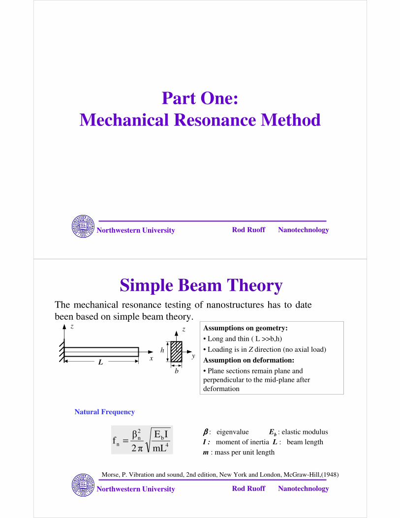
Simple Beam TheoryThe mechanical resonance testing of nanostructures has to date been based on simple beam theory.
Natural Frequency
ββββ : eigenvalue Eb : elastic modulusI : moment of inertia L : beam length m : mass per unit length
y
z
b
h
L x
z Assumptions on geometry:• Long and thin ( L >>b,h)• Loading is in Z direction (no axial load)Assumption on deformation:• Plane sections remain plane and perpendicular to the mid-plane after deformation
Morse, P. Vibration and sound, 2nd edition, New York and London, McGraw-Hill,(1948)
4b
2n
n mLIE
�2�
f =
Northwestern University Rod Ruoff Nanotechnology
Resonance Test PrincipleAccording to simple beam theory, the natural frequency of a cantilevered circular cross-section beam is given by:
The bending modulus can be calculated through measurement of dimension and resonance frequency.
Northwestern University Rod Ruoff Nanotechnology
Electrical Excitation
VdcVac
tV
tVVVVVV
tVVV
acacdcacdc
acdc
ωαωαα
ωα
2cos2
cos)(221
)(
)cos(F(t)2
22
2
++∆+++∆=
++∆=
The mechanical resonance of a cantilevered structure can be excited by applying a periodic load whose frequency equals the natural frequency of the structure.
Northwestern University Rod Ruoff Nanotechnology
Mechanical Excitation
Piezoelectric Actuator
The mechanical resonance of a cantilevered structure can also be mechanically excited through the vibration of its substrate.
The working frequency range of the mechanical excitation method is here limited by the frequency response of the piezoelectric actuator.
Northwestern University Rod Ruoff Nanotechnology
Part Two:Mechanical Resonance
Experiments
Northwestern University Rod Ruoff Nanotechnology
Mechanical Resonance: Carbon Nanotube
Poncharal,P., et al, Science, 283, 1513-1516 (1999)
(top) Elastic properties of nanotubes
(left) Electromechanical vibration of a MWCNT (A) thermal vibration (B) Fundamental resonance (C) First overtone resonance
Northwestern University Rod Ruoff Nanotechnology
Mechanical Resonance: DLC Pillar
Fujita,J. et al, J.Vac.Sci.Technol. B 19(6), 2834-2836 (2001)
SEM image of the vibration Schematic of mechanical vibration experimental setup
Northwestern University Rod Ruoff Nanotechnology
Mechanical Resonance: ZnO Nanobelt
Bai et al, App. Phys. Lett. 82(26) 4806-4808 (2003)
Northwestern University Rod Ruoff Nanotechnology
Mechanical Resonance: ZnO nanobelt (con’t)
Northwestern University Rod Ruoff Nanotechnology
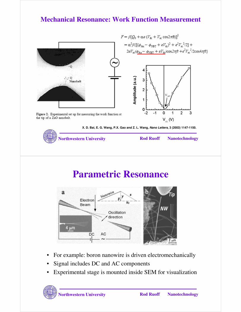
Mechanical Resonance: Work Function Measurement
X. D. Bai, E. G. Wang, P.X. Gao and Z. L. Wang, Nano Letters, 3 (2003) 1147-1150.
Northwestern University Rod Ruoff Nanotechnology
• For example: boron nanowire is driven electromechanically• Signal includes DC and AC components• Experimental stage is mounted inside SEM for visualization
Parametric Resonance
Northwestern University Rod Ruoff Nanotechnology
Electromechanical Driving: Mathieu Equation
• The force due to the electrical field is similar to that on a cantilever between capacitor plates:
• The voltage-induced force on the nanowire increases as the tube bends closer to the electrode:
• Equation for each mode takes the form of the damped Mathieu equation
Northwestern University Rod Ruoff Nanotechnology
Stability of the Mathieu Equation
From: Bender and Orszag, “Advanced Mathematical Methods forScientists and Engineers.”McGraw-Hill, p.562
a = 0.2983εεεε = 0.05µµµµ = 0.01
a = 0.2985εεεε = 0.05µµµµ = 0.01
Unstable
Stable
( ) 0cos22
2
=+++ ytadtdY
dtYd εµ
Northwestern University Rod Ruoff Nanotechnology
Parametric Resonance• Mathieu equation has
unstable solutions for:
• Resonance is observed at driving frequencies that give the unstable values of a:
( ) 0cos22
2
=+++ ytadtdY
dtYd εµ
Min-Feng Yu, Gregory J. Wagner, Rodney S. Ruoff, Mark J. Dyer, Realization of parametric resonances in a nanowire mechanical system with nanomanipulation inside scanning electron microscope, Phys. Rev. B 66, 073406 (2002).
Northwestern University Rod Ruoff Nanotechnology
Instability Regions for Vibrating Nanowire• Small shifts in frequency or driving
voltage can cause switch from unstable to stable behavior
• This instability can be used to sense changes in the environment of a vibrating nanowire
From: Bender and Orszag, “Advanced Mathematical Methods forScientists and Engineers.”McGraw-Hill, p.562
Min-Feng Yu, Gregory J. Wagner, Rodney S. Ruoff, Mark J. Dyer, Realization of parametric resonances in a nanowire mechanical system with nanomanipulation inside scanning electron microscope, Phys. Rev. B 66, 073406 (2002).
Northwestern University Rod Ruoff Nanotechnology
Part Three:Ruoff Group Work
Northwestern University Rod Ruoff Nanotechnology
Experiment Tool: Nanomanipulator• Four-degree of freedom (x,y,z linear motion and rotation)• Two separate stages (X-Y stage, Z-θθθθ stage) • Sub-nanometer motion resolution
Northwestern University Rod Ruoff Nanotechnology
Experimental Setup
(b) Mechanical Excitation
(a) Electrical Excitation
VdcVac
Piezo Bimorph
Counter Electrode
Conductive AFM Cantilever
X-Y StageZ Stage
Piezo Bimorph
AFM Cantilever
X-Y Stage Vac
Nanostructure
Northwestern University Rod Ruoff Nanotechnology
Mechanical Resonance of SiO2 Nanowire
D. A. Dikin, X. Chen, W. Ding, G. Wagner, R. S. Ruoff, Resonance vibration of amorphous SiO2 nanowires driven by mechanical or electrical field excitation, Journal of Applied Physics 93, 226 (2003).
Northwestern University Rod Ruoff Nanotechnology
SiO2 Nanowire: Source
Ultrasonically dispersed SiO2nanowire
Synthesized by Z.W. Pan (J.Am.Chem.Soc.’02)
TEM image (inserts: High resolution image and diffraction pattern)
Northwestern University Rod Ruoff Nanotechnology
SiO2 Nanowire: Mechanical Resonance
Electrical Excitation Mechanical Excitation
W wireW wire
W wire (counter electrode)
Northwestern University Rod Ruoff Nanotechnology
SiO2 Nanowire: Charge TrappingExperiment 1
E-beam modes, time between
scanlines:TV mode 0.06 ms
3-d mode 17 ms
4-th mode 50 ms
12345..
512
2µµµµm
Hitachi S4500
D. A. Dikin, X. Chen, W. Ding, G. Wagner, R. S. Ruoff, Resonance vibration of amorphous SiO2 nanowiresdriven by mechanical or electrical field excitation, Journal of Applied Physics 93, 226 (2003).
Northwestern University Rod Ruoff Nanotechnology
SiO2 Nanowire: Charge TrappingExperiment 2
Contr Electrode
120 140 160 180 2000
10
20
30
40
a
Am
pl. o
f vib
ratio
n, µ
m
Length of NW under loading, µm
v (x)p xEd
( a x)ao= −8
34
3
4πD. A. Dikin, X. Chen, W. Ding, G. Wagner, R. S. Ruoff, Resonance vibration of amorphous SiO2 nanowires
driven by mechanical or electrical field excitation, Journal of Applied Physics 93, 226 (2003).
Northwestern University Rod Ruoff Nanotechnology
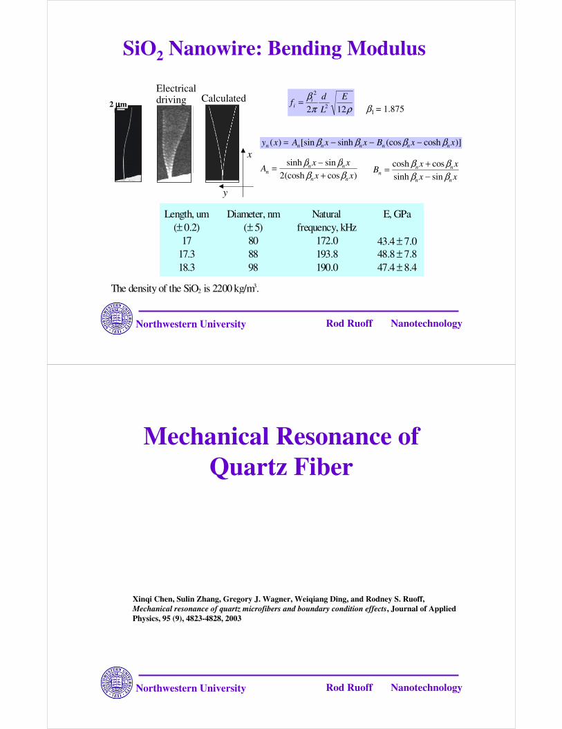
y x A x x B x xn n n n n n n( ) [sin sinh (cos cosh )]= − − −β β β β
Xinqi Chen, Sulin Zhang, Gregory J. Wagner, Weiqiang Ding, and Rodney S. Ruoff, Mechanical resonance of quartz microfibers and boundary condition effects, Journal of Applied Physics, 95 (9), 4823-4828, 2003
Northwestern University Rod Ruoff Nanotechnology
Quartz Fibers
Typical sample geometry: diameter: 30-100 µm, length: 5-10 mm
Quartz fibers were home-made by pulling a fused quartz rod (GE Quartz, Inc) on a wide flame.
Northwestern University Rod Ruoff Nanotechnology
Quartz Fiber: Mechanically Induced Resonance
Optical microscope pictures of the first four modes of resonance of a quartz microfiber. The insets are the theoretical displacement curves.
Northwestern University Rod Ruoff Nanotechnology
Quartz Fiber: Correction for Non-uniform Diameter
Due to the pulling process, the quartz fiber diameter is not quite uniform. The resonance frequency change for a beam of circular cross-section, with linearly varying diameter, was calculated according to the following equation:
α=(D1-D0)/D0 α is generally small.
n=0: f = f0 × (1 - 0.42 α)n=1: f = f0 × (1 + 0.22 α)n=2: f = f0× (1 + 0.42 α)
f0 is the corresponding resonance frequencies of a beam with uniform diameter D0.
D0
D1
fixed end
free end
Northwestern University Rod Ruoff Nanotechnology
Quartz Fiber: Young’s Modulus# L , mm D 0, um D 1,
Note: L: length, D0: the clamped side diameter, D1: the free end diameter, f0: the fundamental resonance frequency, f1: the first overtone resonance frequency.
Northwestern University Rod Ruoff Nanotechnology
Mechanical Resonance of Crystalline Boron Nanowires
W. Ding, L. Calabri, X. Chen, K. Kohlhaas, R.S. Ruoff, Mechanics of Crystalline Boron Nanowires, manuscript in preparation
Northwestern University Rod Ruoff Nanotechnology
Boron Nanowire: Source
SEM image of boron nanowires on alumina substrate TEM image of a boron nanowire
Otten et al, J.Am. Chem. Soc.,124 (17), 2002
Northwestern University Rod Ruoff Nanotechnology
Boron Nanowire: Resonance
First two modes of resonance of a cantilevered BNW
Schematic representation of a wire being partitioned into N segments, before (a) and after (b) rotation.
SEM images only give a two-dimensional projection of the cantilevered nanowire.
It is critical to have accurate length measurement:
A parallax method was used to reconstruct the correct three-dimensional representation of the nanowire based on two SEM images taken from different angles.
Northwestern University Rod Ruoff Nanotechnology
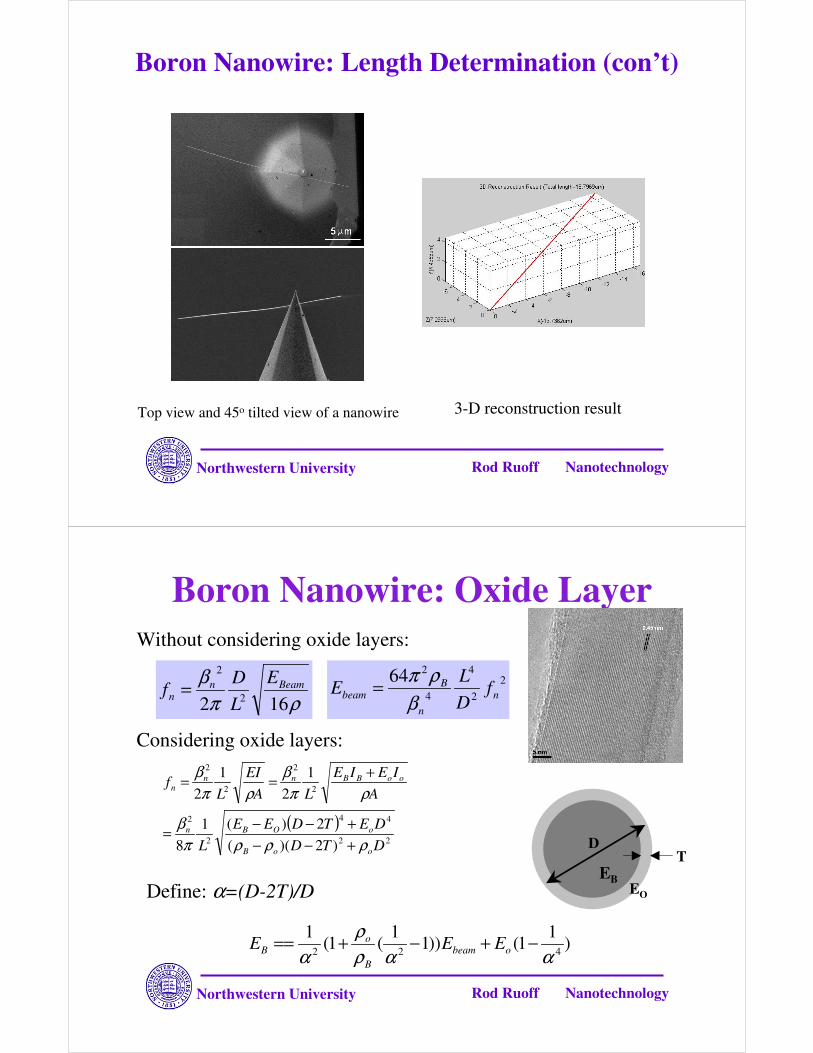
Boron Nanowire: Length Determination (con’t)
Top view and 45o tilted view of a nanowire 3-D reconstruction result
Northwestern University Rod Ruoff Nanotechnology
Boron Nanowire: Oxide Layer
( )22
44
2
2
2
2
2
2
)2)((2)(1
8
12
12
DTDDETDEE
L
AIEIE
LAEI
Lf
ooB
oOBn
ooBBnnn
ρρρπβ
ρπβ
ρπβ
+−−+−−=
+==
)1
1())11
(1(1
422 ααρρ
α−+−+== obeam
B
oB EEE
ρπβ
162 2
2Beamn
n
ELD
f = 22
4
4
264n
n
Bbeam f
DL
Eβ
ρπ=
Without considering oxide layers:
Considering oxide layers:
TD
EBEODefine: α=(D-2T)/D
Northwestern University Rod Ruoff Nanotechnology
Boron Nanowire: Results
Northwestern University Rod Ruoff Nanotechnology
Boron Nanowire: Curved Wire
In-plane vibration Out-of-plane vibration
A curved circular cross-section cantilevered beam can vibrate in two perpendicular directions: (1) in plane and (2) out of plane.
Northwestern University Rod Ruoff Nanotechnology
FEA AnalysisThe simple beam theory is based on the assumption that the beam deflection is due to bending only and that transverse shear, rotatory inertia, and axial extension effects are negligible; for curved beams these assumptions are not correct. Modal analysis was performed on several
curved cantilever nanowires with ANSYS. The FEA model was based on the 3-D reconstruction of the nanowire configuration.
Summary1. Mechanical Resonance method based on simple beam
theory, and some work has been done with FEA
2. There are two commonly used methods to excite the mechanical resonance of cantilevered nanostructures: electrical excitation and mechanical excitation.
3. It is critical to have accurate geometry measurement.
4. Mechanical resonance method is an nondestructive and effective way to determine the elastic modulus of nanostructures; one aspect deserving careful scrutiny in the future is the low values for the modulus often obtained compared to the bulk material.