16
L2 / L3 Switches Remote Network Monitoring (RMON) Configuration Guide Revision 1.0

L2 / L3 Switches
Remote Network Monitoring (RMON)
Configuration Guide
Revision 1.0

Supermicro L2/L3 Switches Configuration Guide 2
The information in this USER’S MANUAL has been carefully reviewed and is believed to be accurate. The vendor
assumes no responsibility for any inaccuracies that may be contained in this document, makes no commitment to
update or to keep current the information in this manual, or to notify any person organization of the updates.
Please Note: For the most up-to-date version of this manual, please see our web site at www.supermicro.com.
Super Micro Computer, Inc. (“Supermicro”) reserves the right to make changes to the product described in this
manual at any time and without notice. This product, including software, if any, and documentation may not, in
whole or in part, be copied, photocopied, reproduced, translated or reduced to any medium or machine without
prior written consent.
IN NO EVENT WILL SUPERMICRO BE LIABLE FOR DIRECT, INDIRECT, SPECIAL, INCIDENTAL, SPECULATIVE OR
CONSEQUENTIAL DAMAGES ARISING FROM THE USE OR INABILITY TO USE THIS PRODUCT OR DOCUMENTATION,
EVEN IF ADVISED OF THE POSSIBILITY OF SUCH DAMAGES. IN PARTICULAR, SUPERMICRO SHALL NOT HAVE
LIABILITY FOR ANY HARDWARE, SOFTWARE, OR DATA STORED OR USED WITH THE PRODUCT, INCLUDING THE
COSTS OF REPAIRING, REPLACING, INTEGRATING, INSTALLING OR RECOVERING SUCH HARDWARE, SOFTWARE, OR
DATA.
Any disputes arising between manufacturer and customer shall be governed by the laws of Santa Clara County in
the State of California, USA. The State of California, County of Santa Clara shall be the exclusive venue for the
resolution of any such disputes. Super Micro's total liability for all claims will not exceed the price paid for the
hardware product.
FCC Statement: This equipment has been tested and found to comply with the limits for a Class A digital device
pursuant to Part 15 of the FCC Rules. These limits are designed to provide reasonable protection against harmful
interference when the equipment is operated in a commercial environment. This equipment generates, uses, and
can radiate radio frequency energy and, if not installed and used in accordance with the manufacturer’s instruction
manual, may cause harmful interference with radio communications. Operation of this equipment in a residential
area is likely to cause harmful interference, in which case you will be required to correct the interference at your
own expense.
California Best Management Practices Regulations for Perchlorate Materials: This Perchlorate warning applies only
to products containing CR (Manganese Dioxide) Lithium coin cells. Perchlorate Material-special handling may
apply. See http://www.dtsc.ca.gov/hazardouswaste/perchlorate/ for further details.
Manual Revision 1.0
Release Date: October 28, 2013
Unless you request and receive written permission from Super Micro Computer, Inc., you may not copy any part of
this document.
Information in this document is subject to change without notice. Other products and companies referred to
herein are trademarks or registered trademarks of their respective companies or mark holders.
Copyright © 2013 by Super Micro Computer, Inc.
All rights reserved.
Printed in the United States of America
Supermicro L2/L3 Switches Configuration Guide 3
Contents 1 RMON Configuration Guide .................................................................................................................. 4
1.1 RMON Overview ........................................................................................................................... 4
1.2 RMON Groups ............................................................................................................................... 6
1.2.1 Alarm group .......................................................................................................................... 6
1.2.2 Event Group .......................................................................................................................... 7
1.2.3 Statistics ................................................................................................................................ 7
1.3 RMON Configuration ..................................................................................................................... 7
1.3.1 Default Configuration ............................................................................................................ 7
1.3.2 Enabling RMON ..................................................................................................................... 8
1.3.3 Configuring Alarms and Events ............................................................................................. 8
1.3.4 Configuring Statistics ........................................................................................................... 10
1.3.5 RMON Configuration Example ............................................................................................ 12
Supermicro L2/L3 Switches Configuration Guide 4
1 RMON Configuration Guide
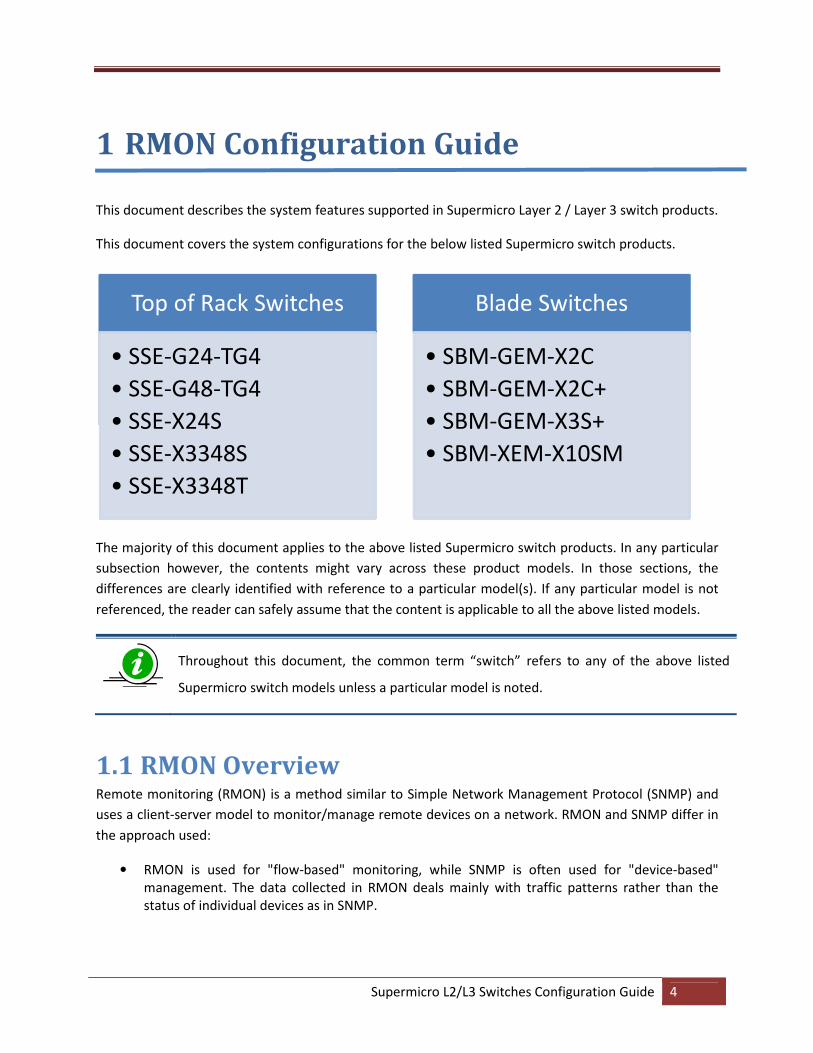
This document describes the system features supported in Supermicro Layer 2 / Layer 3 switch products.
This document covers the system configurations for the below listed Supermicro switch products.
The majority of this document applies to the above listed Supermicro switch products. In any particular
subsection however, the contents might vary across these product models. In those sections, the
differences are clearly identified with reference to a particular model(s). If any particular model is not
referenced, the reader can safely assume that the content is applicable to all the above listed models.
Throughout this document, the common term “switch” refers to any of the above listed
Supermicro switch models unless a particular model is noted.
1.1 RMON Overview Remote monitoring (RMON) is a method similar to Simple Network Management Protocol (SNMP) and
uses a client-server model to monitor/manage remote devices on a network. RMON and SNMP differ in
the approach used:
• RMON is used for "flow-based" monitoring, while SNMP is often used for "device-based"
management. The data collected in RMON deals mainly with traffic patterns rather than the
status of individual devices as in SNMP.
Top of Rack Switches
• SSE-G24-TG4
• SSE-G48-TG4
• SSE-X24S
• SSE-X3348S
• SSE-X3348T
Blade Switches
• SBM-GEM-X2C
• SBM-GEM-X2C+
• SBM-GEM-X3S+
• SBM-XEM-X10SM
Supermicro L2/L3 Switches Configuration Guide 5
• RMON is implemented based on SNMP. RMON sends traps to the management device to notify
the abnormality of the alarm variables by using the SNMP trap mechanism. Traps in RMON and
SNMP have different monitored targets, triggering conditions, and report contents.
• RMON provides an efficient means of monitoring subnets. The managed device sends a trap to
the management device automatically once an alarm has reached a certain threshold value.
Unlike SNMP, the management device does not need to get the values of MIB variables multiple
times for comparison. Hence, the communication traffic between the management device and
the managed device is reduced.
RMON provides statistics and alarm functionality to monitor managed devices.
• The statistics function tracks traffic information on the network segments connected to its
ports; for example, the number of oversize packets received.
• The alarm function aids in monitoring the value of a specified MIB variable. It also handles such
events as traps or logs to be sent to the management device when its value reaches a particular
threshold; for example,when the rate of packets received reaches a certain value.
The RMON protocol allows multiple monitors or management devices. A monitor provides two ways of
data gathering:
• Using RMON probes from which management devices can get data directly and can
control network resources. In this approach, management devices can obtain all RMON
MIB information.
• RMON agents in routers and switches. Management devices exchange data with RMON
agents using SNMP operations. Due to system resources limitation, they may not cover
all MIB information, but in most cases will cover four groups: alarm, event, history, and
statistics.
Supermicro supports minimal RMON agent implementation for Ethernet interfaces.
Supermicro L2/L3 Switches Configuration Guide 6
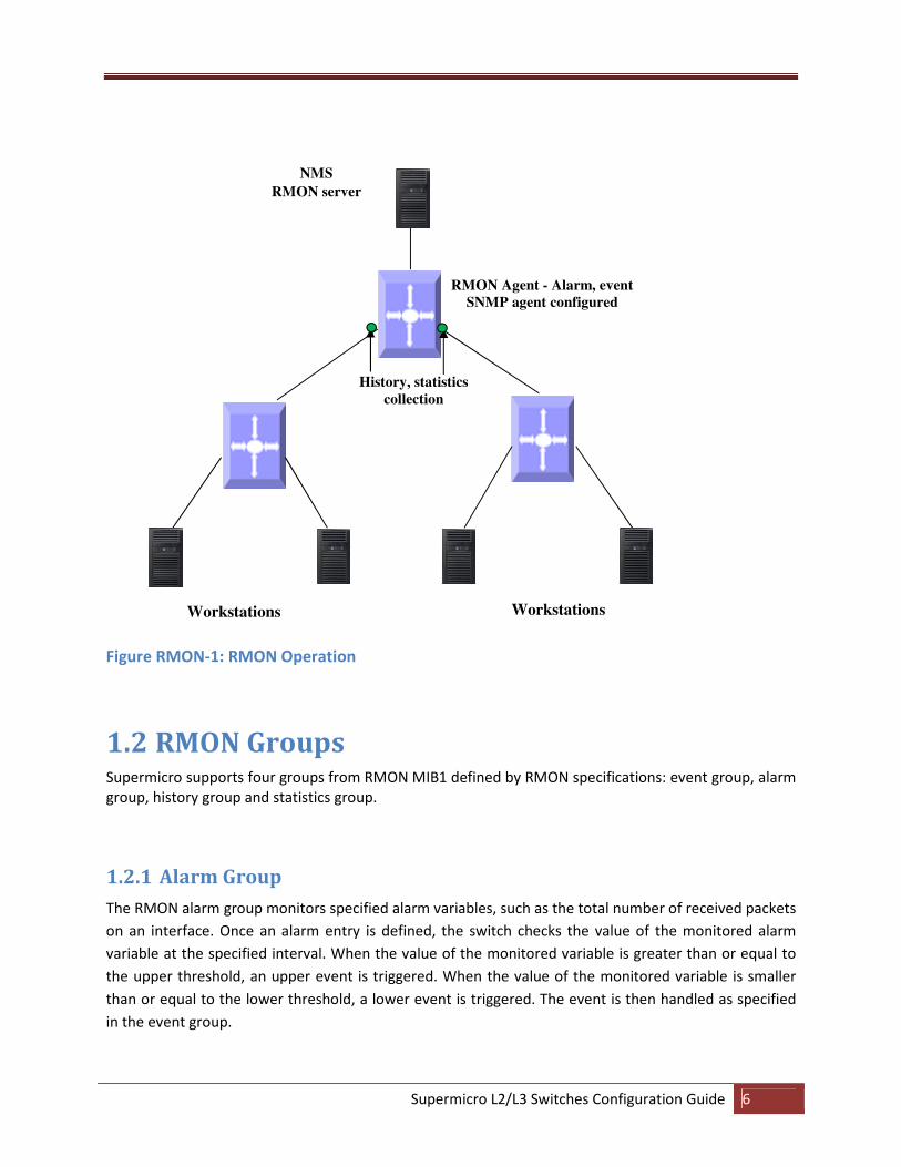
Figure RMON-1: RMON Operation
1.2 RMON Groups Supermicro supports four groups from RMON MIB1 defined by RMON specifications: event group, alarm
group, history group and statistics group.
1.2.1 Alarm Group
The RMON alarm group monitors specified alarm variables, such as the total number of received packets
on an interface. Once an alarm entry is defined, the switch checks the value of the monitored alarm
variable at the specified interval. When the value of the monitored variable is greater than or equal to
the upper threshold, an upper event is triggered. When the value of the monitored variable is smaller
than or equal to the lower threshold, a lower event is triggered. The event is then handled as specified
in the event group.
Workstations
NMS
RMON server
RMON Agent - Alarm, event
SNMP agent configured
Workstations
History, statistics
collection
Supermicro L2/L3 Switches Configuration Guide 7
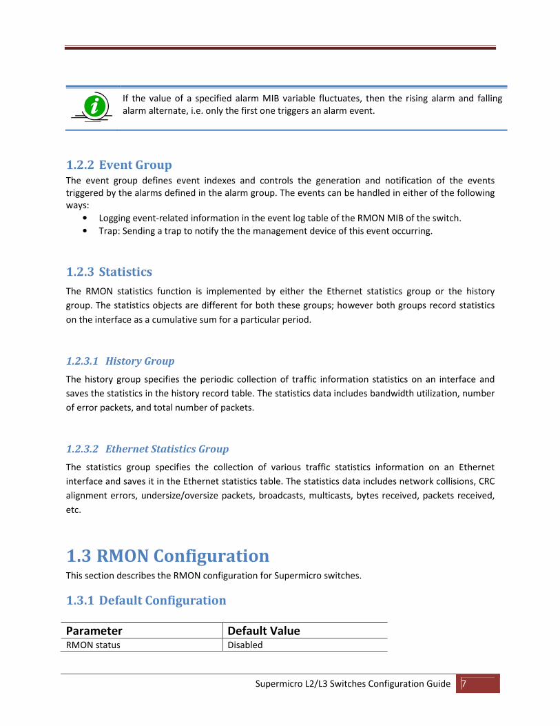
If the value of a specified alarm MIB variable fluctuates, then the rising alarm and falling
alarm alternate, i.e. only the first one triggers an alarm event.
1.2.2 Event Group The event group defines event indexes and controls the generation and notification of the events
triggered by the alarms defined in the alarm group. The events can be handled in either of the following
ways:
• Logging event-related information in the event log table of the RMON MIB of the switch.
• Trap: Sending a trap to notify the the management device of this event occurring.
1.2.3 Statistics
The RMON statistics function is implemented by either the Ethernet statistics group or the history
group. The statistics objects are different for both these groups; however both groups record statistics
on the interface as a cumulative sum for a particular period.
1.2.3.1 History Group
The history group specifies the periodic collection of traffic information statistics on an interface and
saves the statistics in the history record table. The statistics data includes bandwidth utilization, number
of error packets, and total number of packets.
1.2.3.2 Ethernet Statistics Group
The statistics group specifies the collection of various traffic statistics information on an Ethernet
interface and saves it in the Ethernet statistics table. The statistics data includes network collisions, CRC
alignment errors, undersize/oversize packets, broadcasts, multicasts, bytes received, packets received,
etc.
1.3 RMON Configuration This section describes the RMON configuration for Supermicro switches.
1.3.1 Default Configuration
Parameter Default Value RMON status Disabled

Supermicro L2/L3 Switches Configuration Guide 8
Collection Statistics None
Collection History None
Alarms None
Events None
1.3.2 Enabling RMON
RMON is disabled by default in Supermicro switches. Follow the steps below to enable RMON.
Step Command Description Step 1 configure terminal Enters the configuration mode
Step 2 set rmon enable Enables RMON in the switch.
Step 3 end Exits the configuration mode.
Step 4 Show rmon Displays the RMON status.
The “set rmon disable” command disables RMON in the switch.
RMON must be enabled before any other RMON configuration.
The example below shows the commands used to enable RMON.
SMIS# configure terminal
SMIS(config)# set rmon enable
SMIS(config)# end
SMIS# show rmon
RMON is enabled
1.3.3 Configuring Alarms and Events The alarm group periodically takes statistical samples from variables and compares them with the
configured thresholds. When a threshold is crossed, an event is generated using the alarm mechanism.
The event group generates events whenever an alarm condition takes place in the device. The alarm
group calls the event group, so an event must already be created for the alarm to call.
Step Command Description Step 1 configure terminal Enters the configuration mode
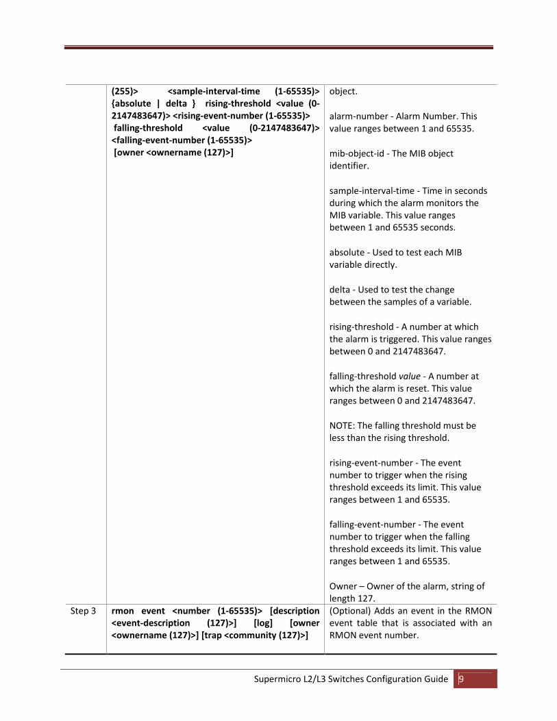
Step 2 rmon alarm <alarm-number> <mib-object-id (Optional) Sets an alarm on an MIB
Supermicro L2/L3 Switches Configuration Guide 9
(255)> <sample-interval-time (1-65535)>
{absolute | delta } rising-threshold <value (0-
2147483647)> <rising-event-number (1-65535)>
falling-threshold <value (0-2147483647)>
<falling-event-number (1-65535)>
[owner <ownername (127)>]
object.
alarm-number - Alarm Number. This
value ranges between 1 and 65535.
mib-object-id - The MIB object
identifier.
sample-interval-time - Time in seconds
during which the alarm monitors the
MIB variable. This value ranges
between 1 and 65535 seconds.
absolute - Used to test each MIB
variable directly.
delta - Used to test the change
between the samples of a variable.
rising-threshold - A number at which
the alarm is triggered. This value ranges
between 0 and 2147483647.
falling-threshold value - A number at
which the alarm is reset. This value
ranges between 0 and 2147483647.
NOTE: The falling threshold must be
less than the rising threshold.
rising-event-number - The event
number to trigger when the rising
threshold exceeds its limit. This value
ranges between 1 and 65535.
falling-event-number - The event
number to trigger when the falling
threshold exceeds its limit. This value
ranges between 1 and 65535.
Owner – Owner of the alarm, string of
length 127.
Step 3 rmon event <number (1-65535)> [description
<event-description (127)>] [log] [owner
<ownername (127)>] [trap <community (127)>]
(Optional) Adds an event in the RMON
event table that is associated with an
RMON event number.
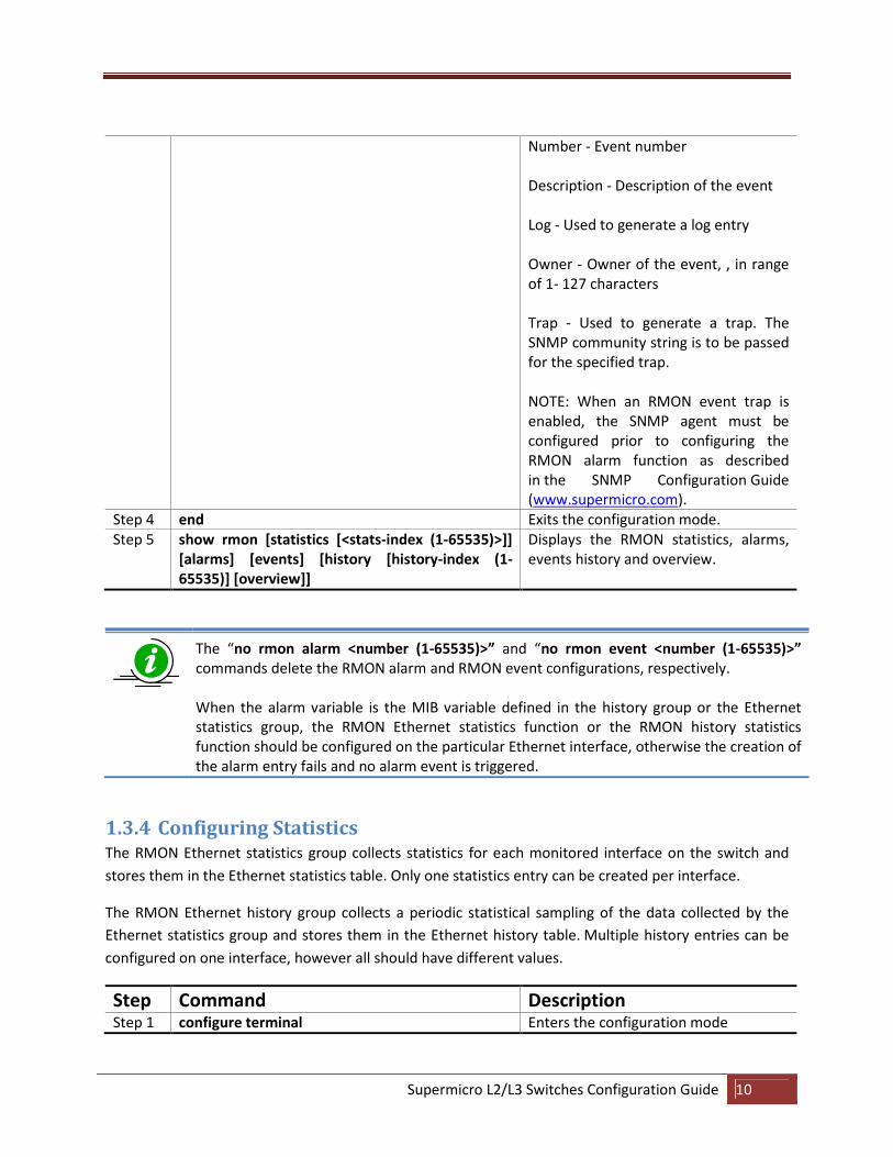
Supermicro L2/L3 Switches Configuration Guide 10
Number - Event number
Description - Description of the event
Log - Used to generate a log entry
Owner - Owner of the event, , in range
of 1- 127 characters
Trap - Used to generate a trap. The
SNMP community string is to be passed
for the specified trap.
NOTE: When an RMON event trap is
enabled, the SNMP agent must be
configured prior to configuring the
RMON alarm function as described
in the SNMP Configuration Guide
(www.supermicro.com).
Step 4 end Exits the configuration mode.
Step 5 show rmon [statistics [<stats-index (1-65535)>]]
[alarms] [events] [history [history-index (1-
65535)] [overview]]
Displays the RMON statistics, alarms,
events history and overview.
The “no rmon alarm <number (1-65535)>” and “no rmon event <number (1-65535)>”
commands delete the RMON alarm and RMON event configurations, respectively.
When the alarm variable is the MIB variable defined in the history group or the Ethernet
statistics group, the RMON Ethernet statistics function or the RMON history statistics
function should be configured on the particular Ethernet interface, otherwise the creation of
the alarm entry fails and no alarm event is triggered.
1.3.4 Configuring Statistics The RMON Ethernet statistics group collects statistics for each monitored interface on the switch and
stores them in the Ethernet statistics table. Only one statistics entry can be created per interface.
The RMON Ethernet history group collects a periodic statistical sampling of the data collected by the
Ethernet statistics group and stores them in the Ethernet history table. Multiple history entries can be
configured on one interface, however all should have different values.
Step Command Description Step 1 configure terminal Enters the configuration mode
Supermicro L2/L3 Switches Configuration Guide 11
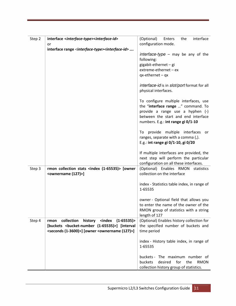
Step 2 interface <interface-type><interface-id>
or
interface range <interface-type><interface-id> ….
(Optional) Enters the interface
configuration mode.
interface-type – may be any of the
following:
gigabit-ethernet – gi
extreme-ethernet – ex
qx-ethernet – qx
interface-id is in slot/port format for all
physical interfaces.
To configure multiple interfaces, use
the “interface range …” command. To
provide a range use a hyphen (-)
between the start and end interface
numbers. E.g.: int range gi 0/1-10
To provide multiple interfaces or
ranges, separate with a comma (,).
E.g.: int range gi 0/1-10, gi 0/20
If multiple interfaces are provided, the
next step will perform the particular
configuration on all these interfaces.
Step 3 rmon collection stats <index (1-65535)> [owner
<ownername (127)>]
(Optional) Enables RMON statistics
collection on the interface
index - Statistics table index, in range of
1-65535
owner - Optional field that allows you
to enter the name of the owner of the
RMON group of statistics with a string
length of 127
Step 4 rmon collection history <index (1-65535)>
[buckets <bucket-number (1-65535)>] [interval
<seconds (1-3600)>] [owner <ownername (127)>]
(Optional) Enables history collection for
the specified number of buckets and
time period
index - History table index, in range of
1-65535
buckets - The maximum number of
buckets desired for the RMON
collection history group of statistics.
Supermicro L2/L3 Switches Configuration Guide 12
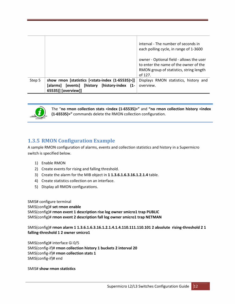
interval - The number of seconds in
each polling cycle, in range of 1-3600
owner - Optional field - allows the user
to enter the name of the owner of the
RMON group of statistics, string length
of 127.
Step 5 show rmon [statistics [<stats-index (1-65535)>]]
[alarms] [events] [history [history-index (1-
65535)] [overview]]
Displays RMON statistics, history and
overview.
The “no rmon collection stats <index (1-65535)>” and “no rmon collection history <index
(1-65535)>” commands delete the RMON collection configuration.
1.3.5 RMON Configuration Example A sample RMON configuration of alarms, events and collection statistics and history in a Supermicro
switch is specified below.
1) Enable RMON
2) Create events for rising and falling threshold.
3) Create the alarm for the MIB object in 1 1.3.6.1.6.3.16.1.2.1.4 table.
4) Create statistics collection on an interface.
5) Display all RMON configurations.
SMIS# configure terminal
SMIS(config)# set rmon enable
SMIS(config)# rmon event 1 description rise log owner smicro1 trap PUBLIC
SMIS(config)# rmon event 2 description fall log owner smicro1 trap NETMAN
SMIS(config)# rmon alarm 1 1.3.6.1.6.3.16.1.2.1.4.1.4.110.111.110.101 2 absolute rising-threshold 2 1
falling-threshold 1 2 owner smicro1
SMIS(config)# interface Gi 0/5
SMIS(config-if)# rmon collection history 1 buckets 2 interval 20
SMIS(config-if)# rmon collection stats 1
SMIS(config-if)# end
SMIS# show rmon statistics
Supermicro L2/L3 Switches Configuration Guide 13
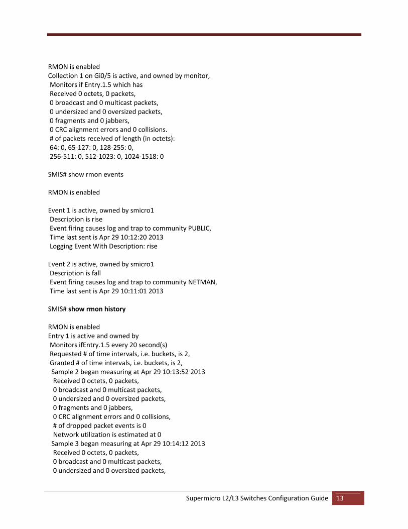
RMON is enabled
Collection 1 on Gi0/5 is active, and owned by monitor,
Monitors if Entry.1.5 which has
Received 0 octets, 0 packets,
0 broadcast and 0 multicast packets,
0 undersized and 0 oversized packets,
0 fragments and 0 jabbers,
0 CRC alignment errors and 0 collisions.
# of packets received of length (in octets):
64: 0, 65-127: 0, 128-255: 0,
256-511: 0, 512-1023: 0, 1024-1518: 0
SMIS# show rmon events
RMON is enabled
Event 1 is active, owned by smicro1
Description is rise
Event firing causes log and trap to community PUBLIC,
Time last sent is Apr 29 10:12:20 2013
Logging Event With Description: rise
Event 2 is active, owned by smicro1
Description is fall
Event firing causes log and trap to community NETMAN,
Time last sent is Apr 29 10:11:01 2013
SMIS# show rmon history
RMON is enabled
Entry 1 is active and owned by
Monitors ifEntry.1.5 every 20 second(s)
Requested # of time intervals, i.e. buckets, is 2,
Granted # of time intervals, i.e. buckets, is 2,
Sample 2 began measuring at Apr 29 10:13:52 2013
Received 0 octets, 0 packets,
0 broadcast and 0 multicast packets,
0 undersized and 0 oversized packets,
0 fragments and 0 jabbers,
0 CRC alignment errors and 0 collisions,
# of dropped packet events is 0
Network utilization is estimated at 0
Sample 3 began measuring at Apr 29 10:14:12 2013
Received 0 octets, 0 packets,
0 broadcast and 0 multicast packets,
0 undersized and 0 oversized packets,
Supermicro L2/L3 Switches Configuration Guide 14
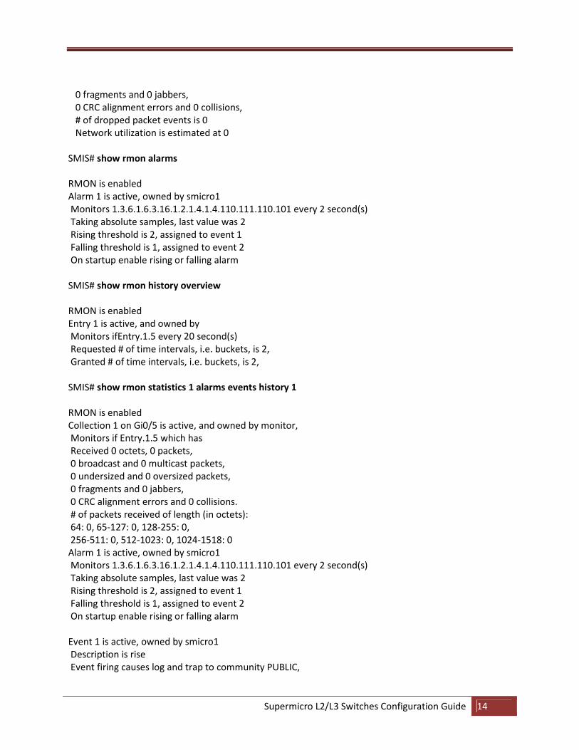
0 fragments and 0 jabbers,
0 CRC alignment errors and 0 collisions,
# of dropped packet events is 0
Network utilization is estimated at 0
SMIS# show rmon alarms
RMON is enabled
Alarm 1 is active, owned by smicro1
Monitors 1.3.6.1.6.3.16.1.2.1.4.1.4.110.111.110.101 every 2 second(s)
Taking absolute samples, last value was 2
Rising threshold is 2, assigned to event 1
Falling threshold is 1, assigned to event 2
On startup enable rising or falling alarm
SMIS# show rmon history overview
RMON is enabled
Entry 1 is active, and owned by
Monitors ifEntry.1.5 every 20 second(s)
Requested # of time intervals, i.e. buckets, is 2,
Granted # of time intervals, i.e. buckets, is 2,
SMIS# show rmon statistics 1 alarms events history 1
RMON is enabled
Collection 1 on Gi0/5 is active, and owned by monitor,
Monitors if Entry.1.5 which has
Received 0 octets, 0 packets,
0 broadcast and 0 multicast packets,
0 undersized and 0 oversized packets,
0 fragments and 0 jabbers,
0 CRC alignment errors and 0 collisions.
# of packets received of length (in octets):
64: 0, 65-127: 0, 128-255: 0,
256-511: 0, 512-1023: 0, 1024-1518: 0
Alarm 1 is active, owned by smicro1
Monitors 1.3.6.1.6.3.16.1.2.1.4.1.4.110.111.110.101 every 2 second(s)
Taking absolute samples, last value was 2
Rising threshold is 2, assigned to event 1
Falling threshold is 1, assigned to event 2
On startup enable rising or falling alarm
Event 1 is active, owned by smicro1
Description is rise
Event firing causes log and trap to community PUBLIC,
Supermicro L2/L3 Switches Configuration Guide 15
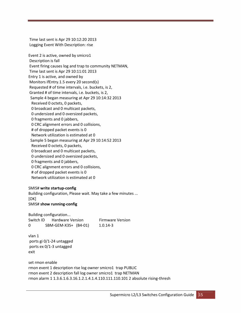
Time last sent is Apr 29 10:12:20 2013
Logging Event With Description: rise
Event 2 is active, owned by smicro1
Description is fall
Event firing causes log and trap to community NETMAN,
Time last sent is Apr 29 10:11:01 2013
Entry 1 is active, and owned by
Monitors ifEntry.1.5 every 20 second(s)
Requested # of time intervals, i.e. buckets, is 2,
Granted # of time intervals, i.e. buckets, is 2,
Sample 4 began measuring at Apr 29 10:14:32 2013
Received 0 octets, 0 packets,
0 broadcast and 0 multicast packets,
0 undersized and 0 oversized packets,
0 fragments and 0 jabbers,
0 CRC alignment errors and 0 collisions,
# of dropped packet events is 0
Network utilization is estimated at 0
Sample 5 began measuring at Apr 29 10:14:52 2013
Received 0 octets, 0 packets,
0 broadcast and 0 multicast packets,
0 undersized and 0 oversized packets,
0 fragments and 0 jabbers,
0 CRC alignment errors and 0 collisions,
# of dropped packet events is 0
Network utilization is estimated at 0
SMIS# write startup-config
Building configuration, Please wait. May take a few minutes ...
[OK]
SMIS# show running-config
Building configuration...
Switch ID Hardware Version Firmware Version
0 SBM-GEM-X3S+ (B4-01) 1.0.14-3
vlan 1
ports gi 0/1-24 untagged
ports ex 0/1-3 untagged
exit
set rmon enable
rmon event 1 description rise log owner smicro1 trap PUBLIC
rmon event 2 description fall log owner smicro1 trap NETMAN
rmon alarm 1 1.3.6.1.6.3.16.1.2.1.4.1.4.110.111.110.101 2 absolute rising-thresh
Supermicro L2/L3 Switches Configuration Guide 16
old 2 1 falling-threshold 1 2 owner smicro1
interface Gi 0/5
rmon collection stats 1 owner monitor
rmon collection history 1 buckets 2 interval 20
exit


