24
L2000 Technical Training 6. Assemble/Disassemble
| Date post: | 16-Dec-2015 |
| Category: |
Documents |
| Upload: | keely-dennington |
| View: | 225 times |
| Download: | 1 times |
L2000Technical Training
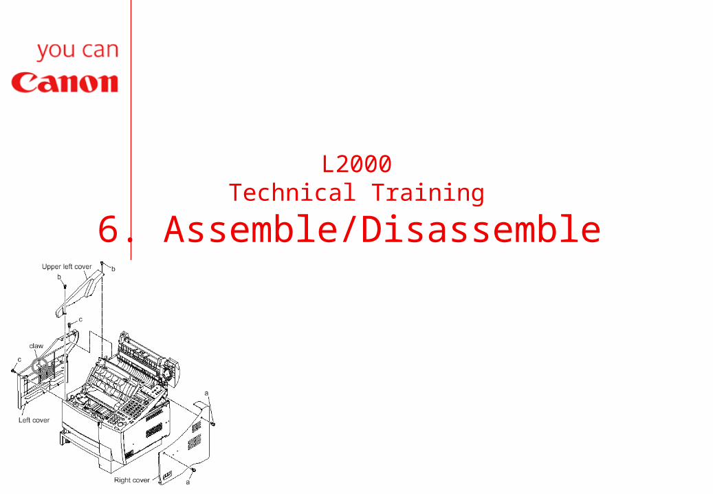
6. Assemble/Disassemble

Disassembly Procedure Document separation roller
(Lower) (1) Remove the document
tray, and open the upper reader section. When doing so, try pushing the left claw toward the inside.
(2) Remove the 3 screws (a), and detach the middle reader cover.
(3) Lift the separation roller, and detach it from the holder.
(4) Pull the separation roller to the left, out of the ADF connection shaft, to detach.

Disassembly Procedure Document separation roller
(Upper) (1) Remove the document tray,
and open the upper reader section. When doing so, try pushing the left claw toward the inside.
(2) Remove the 2 screws (a), and detach the upper reader cover; then, close the upper reader section.
(3) Remove the screw (b), and detach the arm and spring.
(4) Detach the sensor board. (5) Remove the 2 screws (c), and
detach the grounding plate.

Disassembly Procedure Document separation roller
(Upper) con’t (6) Pull out the shaft, and
pull the gear (found at the front) upward to detach.
(7) Detach the left retaining ring.
(8) While detaching the claw, detach the right gear.
(9) Detach the bushings from both sides; then, detach the separation roller ass’y (upper).

Disassembly Procedure Paper pick-up roller and
separation pad (Multi-purpose) (1) Remove the 2 screws (a),
and detach the right cover. (2) Remove the 7 screws (b),
and detach the shield plate.
(3) Remove the 2 screws (c), and detach the upper left cover.
(4) Remove the 2 screws (d); then while freeing the claw, detach the left cover.

Disassembly Procedure Paper pick-up roller and
separation pad (Multi-purpose) con’t (5) Remove the 4 screws
(e), and detach the rear right cover.

Disassembly Procedure Paper pick-up roller and separation
pad (Multi-purpose) con’t (6) Disconnect the connectors J5 and
J6 of the PCL board. (FAX-L2000IP) (7) Remove the screw (f), and detach
the clamp. (8) Disconnect the two connectors of
the NIC board; then, remove the 6 screws (g), and detach the PCL/NIC unit. (FAX-L2000IP)
(9) Disconnect the connector J32 of the SCNT board; then, remove the 4 screws (h), and detach the operation panel ass’y.
(10) Disconnect the connectors J801, J803, J804, and J805 of the SCNT board; then, remove the 5 screws (i), and detach the reader ass’y.
(11) Remove the screw (j), and detach the front right cover.
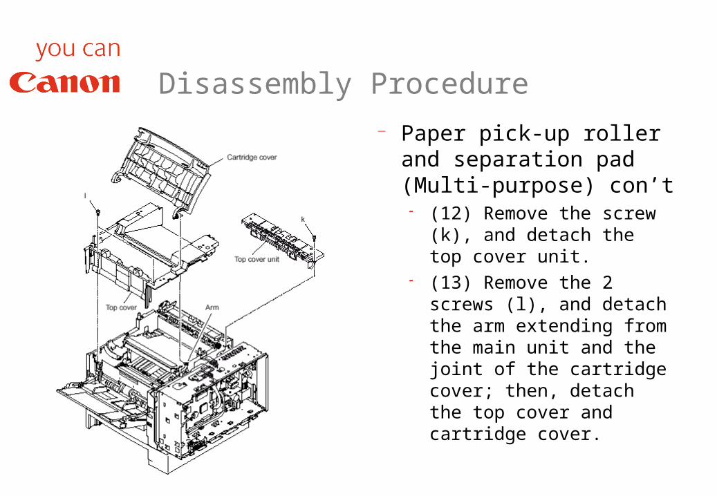
Disassembly Procedure Paper pick-up roller and
separation pad (Multi-purpose) con’t (12) Remove the screw
(k), and detach the top cover unit.
(13) Remove the 2 screws (l), and detach the arm extending from the main unit and the joint of the cartridge cover; then, detach the top cover and cartridge cover.

Disassembly Procedure Paper pick-up roller
and separation pad (Multi-purpose) con’t (14) Remove the 2
springs from the machine side; then, detach the multi-purpose tray ass’y from the front cover ass’y and the left and right hinges.

Disassembly Procedure Paper pick-up roller
and separation pad (Multi-purpose) con’t (15) Shift the front
cover ass’y to the left to detach.

Disassembly Procedure Paper pick-up roller
and separation pad (Multi-purpose) con’t (16) While spreading
open the roller claw found to the right of the pick-up roller, shift the roller to the right.
(17) While spreading open the claw of the pick-up roller, shift the roller to the right; then, as if to rotate it toward the front, detach the pick-up roller.

Disassembly Procedure Paper pick-up
roller and separation pad (Multi-purpose) con’t (18) Remove the
screw (m), and slide out the separation pad to the front to detach.

Disassembly Procedure Paper pick-up roller
(Main unit) (1) Remove the 2
screws (a), and detach the right cover.
(2) Remove the 2 screws (b), and detach the upper left cover.
(3) Remove the 2 screws (c); then, while freeing the claw, detach the left cover.

Disassembly Procedure Paper pick-up
roller (Main unit) con’t (4) Remove the 4
screws (d), and detach the cassette feeder ass’y.

Disassembly Procedure Paper pick-up roller
(Feeder) (1) Remove the 2
screws (a), and detach the right cover.
(2) Remove the 2 screws (b), and detach the upper left cover.
(3) Remove the 2 screws (c); then, while freeing the claw, detach the left over.

Disassembly Procedure Paper pick-up
roller (Feeder) con’t (4) Remove the 4
screws (d), and detach the cassette feeder ass’y.

Disassembly Procedure Paper pick-up
roller (Main unit) con’t (5) Take out the
toner cartridge; then, turn over the main unit.
(6) Remove the 2 bushings; then, while shifting the pick-up roller to the left and right, detach it.

Disassembly Procedure Paper pick-up roller
(Feeder) con’t (5) Turn over the
cassette feeder ass’y, and remove the feeder bottom cover. (You will find a claw behind each cover.)
(6) Remove the 2 bushings by moving them toward the outside, and detach the roller
guide. (7) While shifting the
pick-up roller to the left and right, detach it.

Disassembly Procedure Separation pad
(Cassette) (1) Take out the recording
paper from the recording paper cassette.
(2) While pushing the left and right claws of the separation pad with a precision screwdriver, detach the pad by pulling it upward.

Disassembly Procedure Fixing ass’y
(1) Remove the 2 screws (a), and detach the right cover.
(2) Remove the 2 screws (b), and detach the upper left cover.
(3) Remove the 2 screws (c); then, while freeing the claw, detach the left cover.
(4) Remove the 4 screws (d), and detach the rear right cover.

Disassembly Procedure Fixing ass’y Con’t
(5) Open the rear cover, and remove the 2 screws (e).
(6) Close the rear cover; then, while freeing the left and right claws at the bottom, detach the rear cover ass’y.

Disassembly Procedure Fixing ass’y Con’t
(7) Remove the 2 screws (f), and detach the reverse guide ass’y.
(8) Remove the 3 cables (g).
(9) Remove the 2 screws (h), and pull out the fixing ass’y to detach.

Any Questions?

Objective
You should now be able to demonstrate an understanding of assembly and disassembly of the FAX L2000.
Now let’s look at theI-Functions


