32
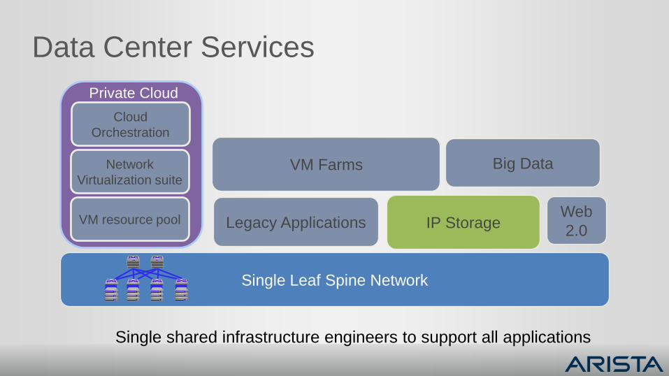
Data Center Services
Private Cloud
Big Data
IP Storage
VM Farms
Legacy ApplicationsWeb
2.0VM resource pool
Network
Virtualization suite
Cloud
Orchestration
Single Leaf Spine Network
Single shared infrastructure engineers to support all applications
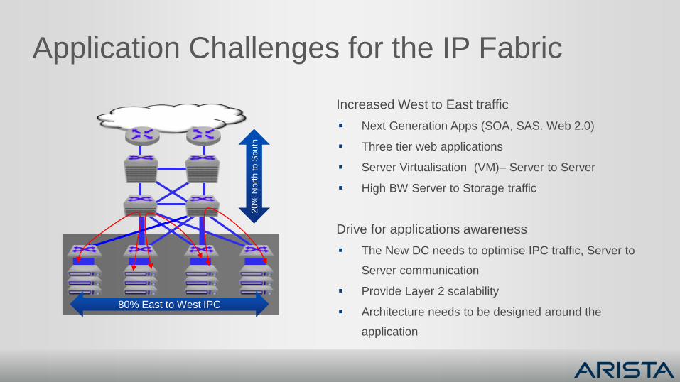
Application Challenges for the IP Fabric
Increased West to East traffic
Next Generation Apps (SOA, SAS. Web 2.0)
Three tier web applications
Server Virtualisation (VM)– Server to Server
High BW Server to Storage traffic
Drive for applications awareness
The New DC needs to optimise IPC traffic, Server to
Server communication
Provide Layer 2 scalability
Architecture needs to be designed around the
application
80% East to West IPC
20
% N
ort
h to
So
uth
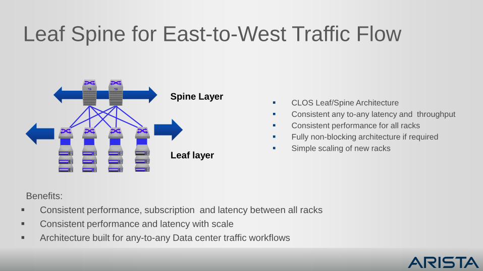
Leaf Spine for East-to-West Traffic Flow
CLOS Leaf/Spine Architecture
Consistent any to-any latency and throughput
Consistent performance for all racks
Fully non-blocking architecture if required
Simple scaling of new racks
Benefits:
Consistent performance, subscription and latency between all racks
Consistent performance and latency with scale
Architecture built for any-to-any Data center traffic workflows
Spine Layer
Leaf layer
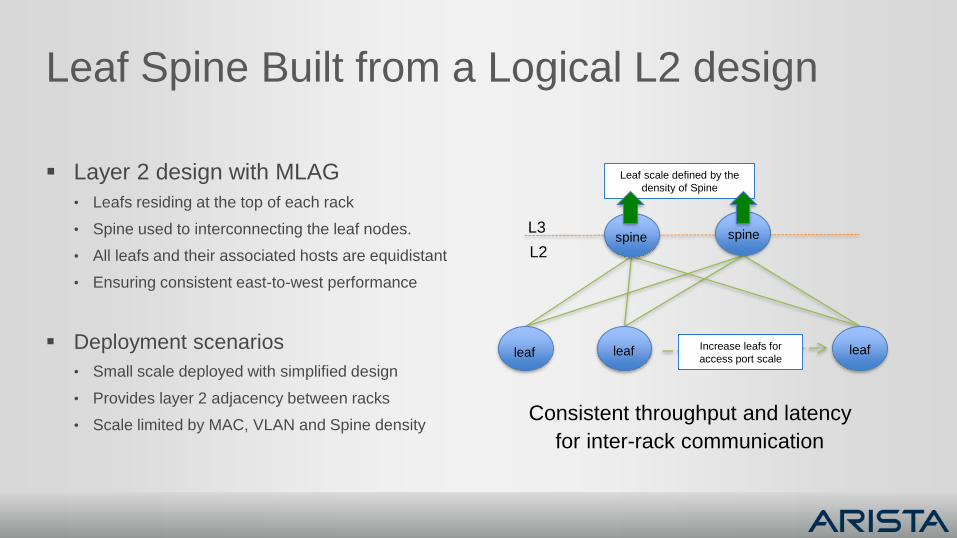
Leaf Spine Built from a Logical L2 design
Layer 2 design with MLAG
• Leafs residing at the top of each rack
• Spine used to interconnecting the leaf nodes.
• All leafs and their associated hosts are equidistant
• Ensuring consistent east-to-west performance
Deployment scenarios
• Small scale deployed with simplified design
• Provides layer 2 adjacency between racks
• Scale limited by MAC, VLAN and Spine densityConsistent throughput and latency
for inter-rack communication
Leaf scale defined by the
density of Spine
Increase leafs for
access port scale
spine spine
leaf leaf leaf
L3
L2
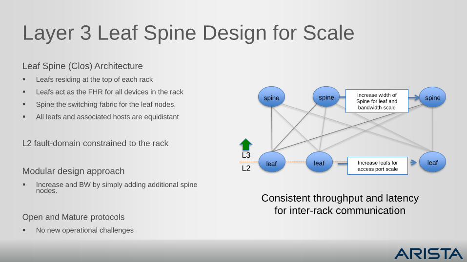
Layer 3 Leaf Spine Design for Scale
Leaf Spine (Clos) Architecture
Leafs residing at the top of each rack
Leafs act as the FHR for all devices in the rack
Spine the switching fabric for the leaf nodes.
All leafs and associated hosts are equidistant
L2 fault-domain constrained to the rack
Modular design approach
Increase and BW by simply adding additional spine nodes.
Open and Mature protocols
No new operational challenges
Consistent throughput and latency
for inter-rack communication
L3
L2
Increase width of
Spine for leaf and
bandwidth scale
Increase leafs for
access port scale
spine spine spine
leaf leaf leaf
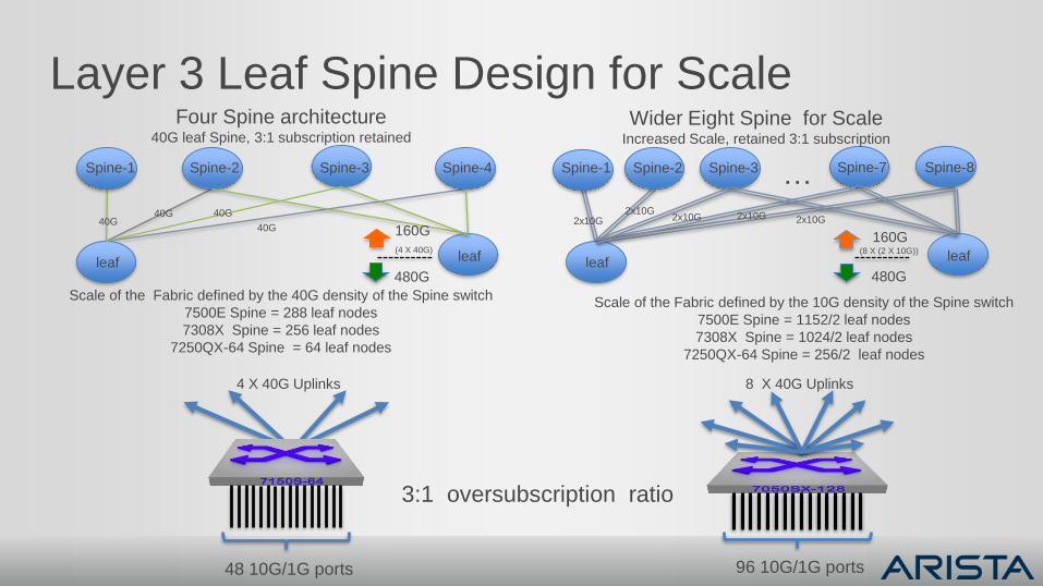
Layer 3 Leaf Spine Design for Scale
Spine-1 Spine-2 Spine-4
leaf
Spine-3
leaf
40G40G
40G
40G
Scale of the Fabric defined by the 40G density of the Spine switch
7500E Spine = 288 leaf nodes
7308X Spine = 256 leaf nodes
7250QX-64 Spine = 64 leaf nodes
160G
(4 X 40G)
480G
Four Spine architecture40G leaf Spine, 3:1 subscription retained
leaf leaf
2x10G
Scale of the Fabric defined by the 10G density of the Spine switch
7500E Spine = 1152/2 leaf nodes
7308X Spine = 1024/2 leaf nodes
7250QX-64 Spine = 256/2 leaf nodes
160G(8 X (2 X 10G))
480G
Spine-1 Spine-2 Spine-8Spine-7Spine-3 …2x10G
2x10G 2x10G 2x10G
Wider Eight Spine for ScaleIncreased Scale, retained 3:1 subscription
3:1 oversubscription ratio
48 10G/1G ports
4 X 40G Uplinks
96 10G/1G ports
8 X 40G Uplinks
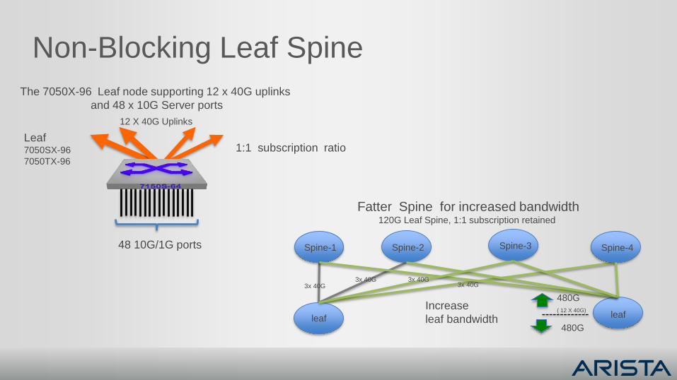
Non-Blocking Leaf Spine
Fatter Spine for increased bandwidth120G Leaf Spine, 1:1 subscription retained
Spine-1 Spine-2 Spine-4
leaf
Spine-3
leaf
3x 40G
480G
( 12 X 40G)
480G
3x 40G 3x 40G3x 40G
Increase
leaf bandwidth
The 7050X-96 Leaf node supporting 12 x 40G uplinks
and 48 x 10G Server ports
Leaf7050SX-96
7050TX-96
12 X 40G Uplinks
48 10G/1G ports
1:1 subscription ratio
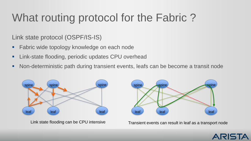
What routing protocol for the Fabric ?
Link state protocol (OSPF/IS-IS)
Fabric wide topology knowledge on each node
Link-state flooding, periodic updates CPU overhead
Non-deterministic path during transient events, leafs can be become a transit node
spine spine spine
leaf leaf leaf
spine spine spine
leaf leaf leaf
Link state flooding can be CPU intensive Transient events can result in leaf as a transport node
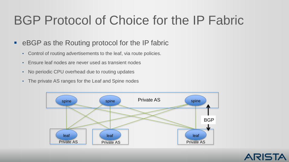
BGP Protocol of Choice for the IP Fabric
eBGP as the Routing protocol for the IP fabric
• Control of routing advertisements to the leaf, via route policies.
• Ensure leaf nodes are never used as transient nodes
• No periodic CPU overhead due to routing updates
• The private AS ranges for the Leaf and Spine nodes
spine spine spine
leaf leaf leaf
Private AS
Private AS
Private AS Private AS
BGP
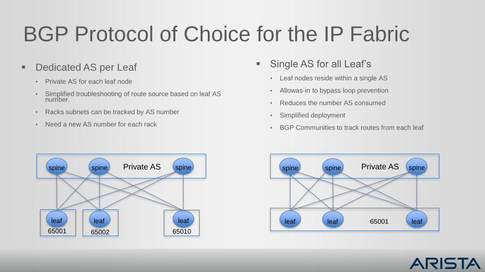
BGP Protocol of Choice for the IP Fabric
Dedicated AS per Leaf
• Private AS for each leaf node
• Simplified troubleshooting of route source based on leaf AS number.
• Racks subnets can be tracked by AS number
• Need a new AS number for each rack
Single AS for all Leaf’s
• Leaf nodes reside within a single AS
• Allowas-in to bypass loop prevention
• Reduces the number AS consumed
• Simplified deployment
• BGP Communities to track routes from each leaf
spine spine spine
leaf leaf leaf
65002
Private AS
65001 65010
spine spine spine
leaf leaf leaf
Private AS
65001
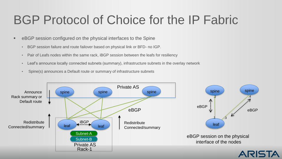
BGP Protocol of Choice for the IP Fabric
eBGP session configured on the physical interfaces to the Spine
• BGP session failure and route failover based on physical link or BFD- no IGP.
• Pair of Leafs nodes within the same rack, iBGP session between the leafs for resiliency
• Leaf’s announce locally connected subnets (summary), infrastructure subnets in the overlay network
• Spine(s) announces a Default route or summary of infrastructure subnets
leaf
Announce
Rack summary or
Default route
spine spine spine
leaf leaf
Private AS
Subnet-A
Subnet-B
Rack-1
iBGPRedistribute
Connected/summaryRedistribute
Connected/summary
Private AS
eBGP
spine spine
.1 .3
.2 .4
eBGPeBGP
eBGP session on the physical
interface of the nodes
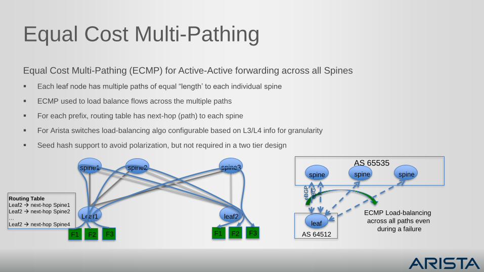
Equal Cost Multi-Pathing
Equal Cost Multi-Pathing (ECMP) for Active-Active forwarding across all Spines
Each leaf node has multiple paths of equal “length’ to each individual spine
ECMP used to load balance flows across the multiple paths
For each prefix, routing table has next-hop (path) to each spine
For Arista switches load-balancing algo configurable based on L3/L4 info for granularity
Seed hash support to avoid polarization, but not required in a two tier design
spine1 spine2 spine3
Leaf1 leaf2
F1 F2 F3 F1 F2 F3
Routing Table
Leaf2 next-hop Spine1
Leaf2 next-hop Spine2
…
Leaf2 next-hop Spine4
spine spine spine
leaf
AS 64512
AS 65535
eB
G
P
eB
GP
ECMP Load-balancing
across all paths even
during a failure
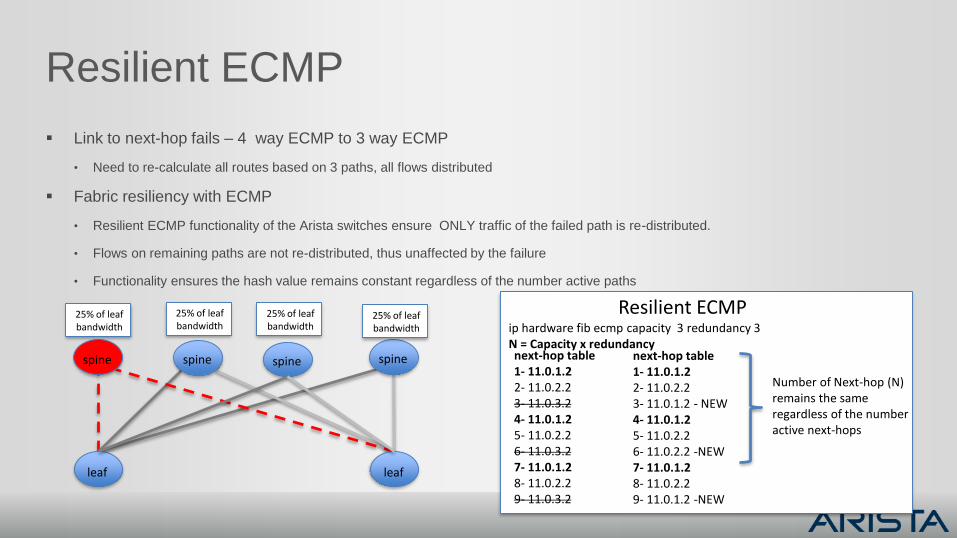
Resilient ECMP
Link to next-hop fails – 4 way ECMP to 3 way ECMP
• Need to re-calculate all routes based on 3 paths, all flows distributed
Fabric resiliency with ECMP
• Resilient ECMP functionality of the Arista switches ensure ONLY traffic of the failed path is re-distributed.
• Flows on remaining paths are not re-distributed, thus unaffected by the failure
• Functionality ensures the hash value remains constant regardless of the number active paths
spine spine spine
leaf leaf
spine
25% of leafbandwidth
25% of leafbandwidth
25% of leafbandwidth
25% of leafbandwidth
next-hop table1- 11.0.1.22- 11.0.2.23- 11.0.3.24- 11.0.1.25- 11.0.2.26- 11.0.3.27- 11.0.1.28- 11.0.2.29- 11.0.3.2
Number of Next-hop (N) remains the same regardless of the number active next-hops
next-hop table1- 11.0.1.22- 11.0.2.23- 11.0.1.2 - NEW4- 11.0.1.25- 11.0.2.26- 11.0.2.2 -NEW7- 11.0.1.28- 11.0.2.29- 11.0.1.2 -NEW
ip hardware fib ecmp capacity 3 redundancy 3N = Capacity x redundancy
Resilient ECMP
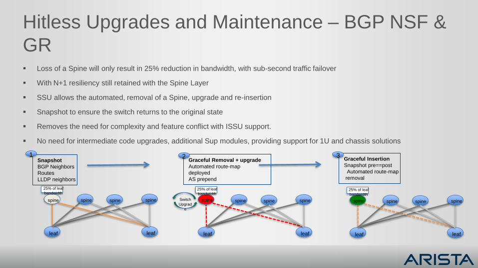
Hitless Upgrades and Maintenance – BGP NSF &
GR Loss of a Spine will only result in 25% reduction in bandwidth, with sub-second traffic failover
With N+1 resiliency still retained with the Spine Layer
SSU allows the automated, removal of a Spine, upgrade and re-insertion
Snapshot to ensure the switch returns to the original state
Removes the need for complexity and feature conflict with ISSU support.
No need for intermediate code upgrades, additional Sup modules, providing support for 1U and chassis solutions
spine spine spine
leaf leaf
spine
25% of leaf
bandwidth
Snapshot
BGP Neighbors
Routes
LLDP neighbors
Graceful Removal + upgrade
Automated route-map
deployed
AS prepend
Graceful Insertion
Snapshot pre==post
Automated route-map
removal
spine spine spine
leaf leaf
spine
25% of leaf
bandwidth
spine spine spine
leaf leaf
spine
25% of leaf
bandwidth
1 2 3
Switch
Upgrad
e
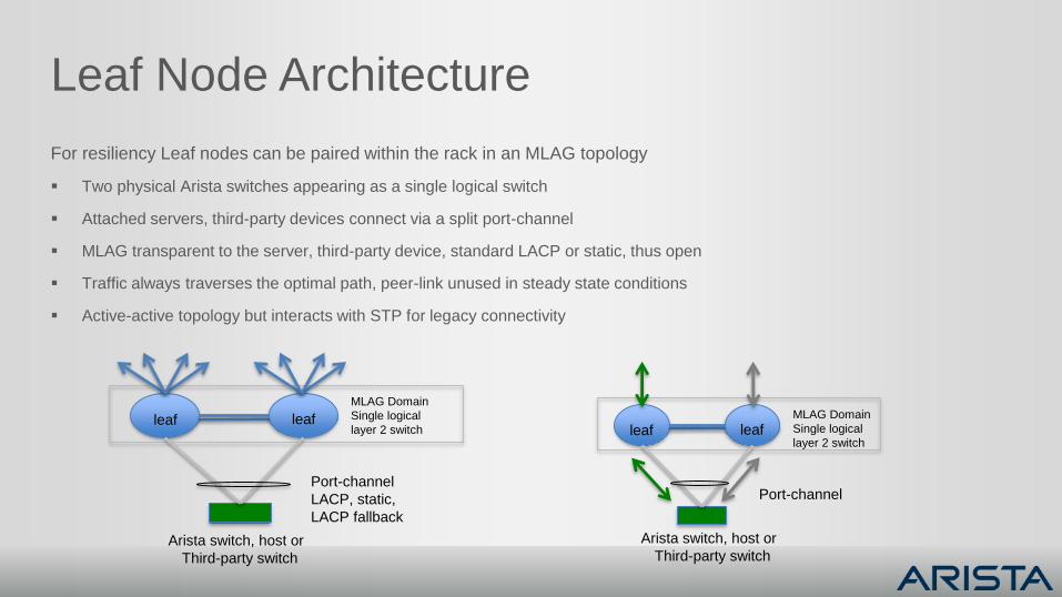
Leaf Node Architecture
For resiliency Leaf nodes can be paired within the rack in an MLAG topology
Two physical Arista switches appearing as a single logical switch
Attached servers, third-party devices connect via a split port-channel
MLAG transparent to the server, third-party device, standard LACP or static, thus open
Traffic always traverses the optimal path, peer-link unused in steady state conditions
Active-active topology but interacts with STP for legacy connectivity
leaf leaf
MLAG Domain
Single logical
layer 2 switch
Arista switch, host or
Third-party switch
Port-channel
LACP, static,
LACP fallback
leaf leafMLAG Domain
Single logical
layer 2 switch
Port-channel
Arista switch, host or
Third-party switch
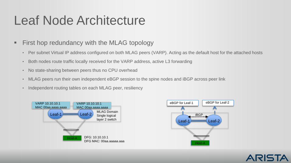
Leaf Node Architecture
First hop redundancy with the MLAG topology
• Per subnet Virtual IP address configured on both MLAG peers (VARP). Acting as the default host for the attached hosts
• Both nodes route traffic locally received for the VARP address, active L3 forwarding
• No state-sharing between peers thus no CPU overhead
• MLAG peers run their own independent eBGP session to the spine nodes and iBGP across peer link
• Independent routing tables on each MLAG peer, resiliency
Leaf-1 Leaf-2
Host-A
MLAG Domain
Single logical
layer 2 switch
VARP 10.10.10.1
MAC 00aa.aaaa.aaaa
DFG: 10.10.10.1
DFG MAC: 00aa.aaaaa.aaa
VARP 10.10.10.1
MAC 00aa.aaaa.aaaa
Leaf-1 Leaf-2
eBGP for Leaf-1 eBGP for Leaf-2
Host-A
iBGP
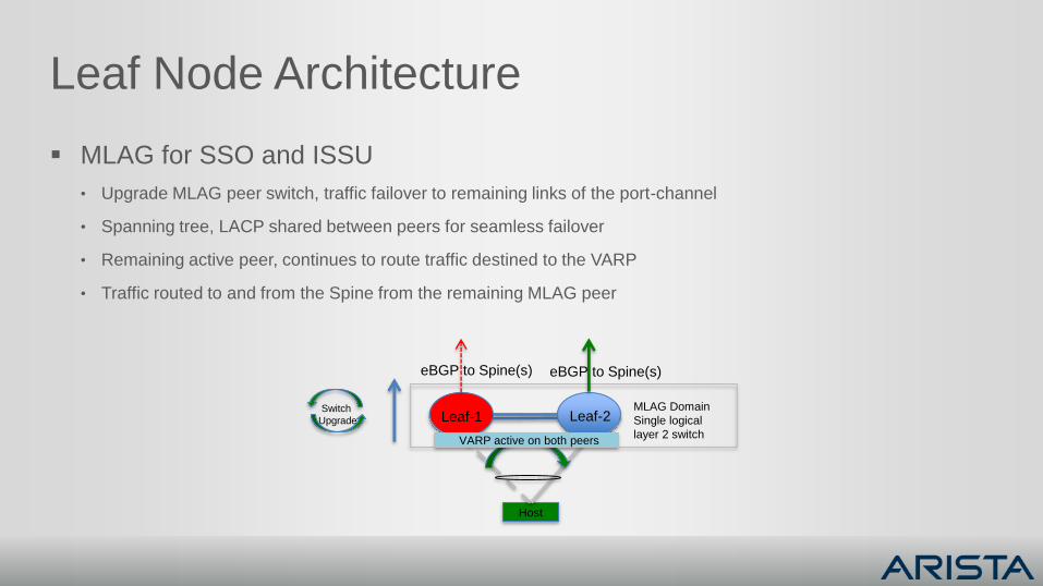
Leaf Node Architecture
MLAG for SSO and ISSU
• Upgrade MLAG peer switch, traffic failover to remaining links of the port-channel
• Spanning tree, LACP shared between peers for seamless failover
• Remaining active peer, continues to route traffic destined to the VARP
• Traffic routed to and from the Spine from the remaining MLAG peer
Leaf-1 Leaf-2
Host
MLAG Domain
Single logical
layer 2 switchVARP active on both peers
eBGP to Spine(s) eBGP to Spine(s)
Switch
Upgrade
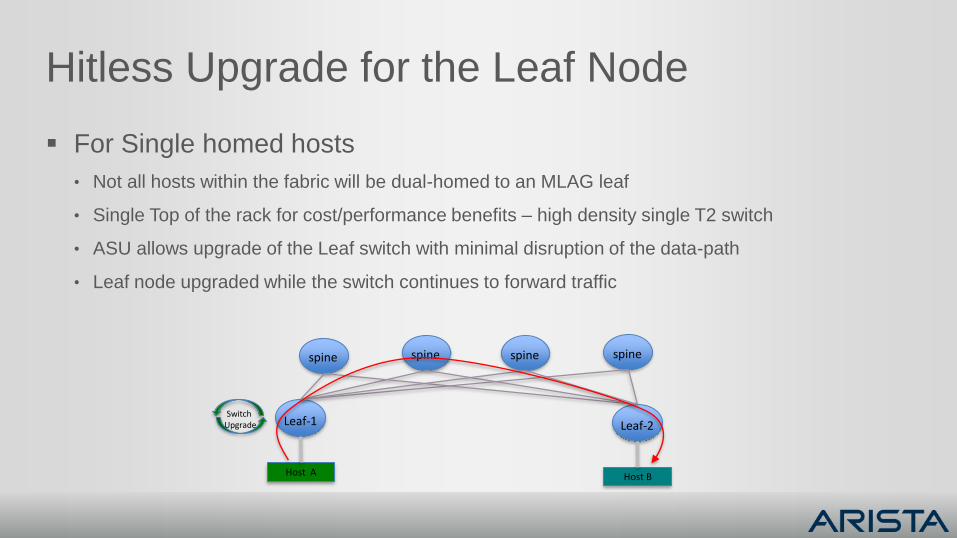
Hitless Upgrade for the Leaf Node
For Single homed hosts
• Not all hosts within the fabric will be dual-homed to an MLAG leaf
• Single Top of the rack for cost/performance benefits – high density single T2 switch
• ASU allows upgrade of the Leaf switch with minimal disruption of the data-path
• Leaf node upgraded while the switch continues to forward traffic
Leaf-1
Host A
spine spinespinespine
Leaf-2
Host B
Switch Upgrade
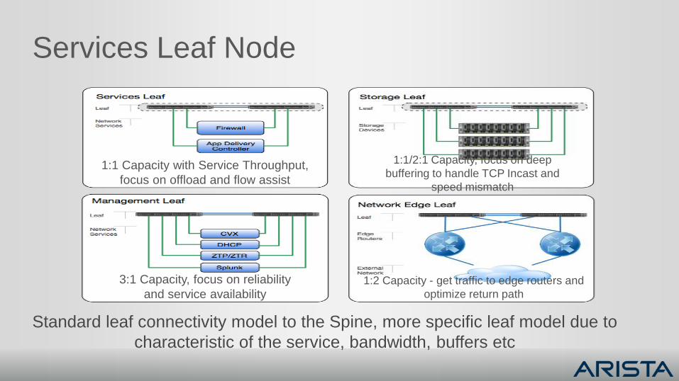
Services Leaf Node
1:1 Capacity with Service Throughput,
focus on offload and flow assist
1:1/2:1 Capacity, focus on deep
buffering to handle TCP Incast and
speed mismatch
3:1 Capacity, focus on reliability
and service availability1:2 Capacity - get traffic to edge routers and
optimize return path
Standard leaf connectivity model to the Spine, more specific leaf model due to
characteristic of the service, bandwidth, buffers etc
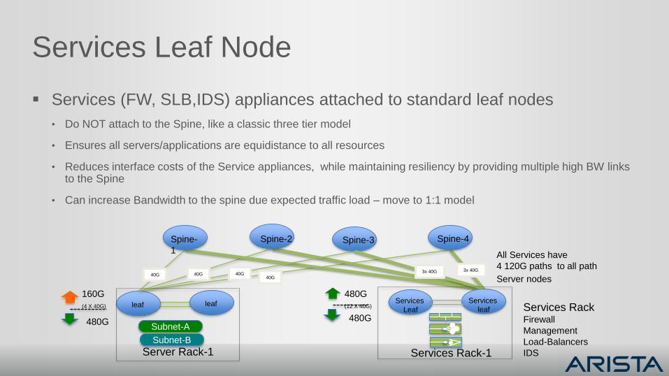
Services Leaf Node
Services (FW, SLB,IDS) appliances attached to standard leaf nodes
• Do NOT attach to the Spine, like a classic three tier model
• Ensures all servers/applications are equidistance to all resources
• Reduces interface costs of the Service appliances, while maintaining resiliency by providing multiple high BW links to the Spine
• Can increase Bandwidth to the spine due expected traffic load – move to 1:1 model
Spine-2
leaf
Spine-3Spine-
1
Spine-4
leaf
Subnet-A
Subnet-B
Server Rack-1
Services
Leaf
Services
leaf
Services Rack-1
Services RackFirewall
Management
Load-Balancers
IDS
160G
(4 X 40G)
480G
480G
(12 X 40G)
480G
40G 40G 40G40G
3x 40G3x 40G
All Services have
4 120G paths to all path
Server nodes
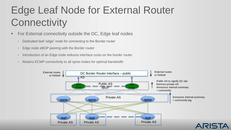
Edge Leaf Node for External Router
Connectivity For External connectivity outside the DC, Edge leaf nodes
• Dedicated leaf ‘edge” node for connecting to the Border router
• Edge node eBGP peering with the Border router
• Introduction of an Edge node reduces interface costs on the border router
• Retains ECMP connectivity to all spine nodes for optimal bandwidth
spine spine spine
leaf leaf leaf
Private AS Private AS
Private AS
leaf
Edgeleaf
Edge
Public AS
iBGP
DC Border Router interface – public
AS
Private AS
External routes
or Default
External routes
or Default
Public AS to signify DC site
Remove private AS
Announce internal summary
+ community
Announce internal summary
+ community tag
Network Virtualization
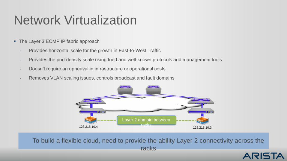
Network Virtualization
The Layer 3 ECMP IP fabric approach
- Provides horizontal scale for the growth in East-to-West Traffic
- Provides the port density scale using tried and well-known protocols and management tools
- Doesn’t require an upheaval in infrastructure or operational costs.
- Removes VLAN scaling issues, controls broadcast and fault domains
128.218.10.4 128.218.10.3
Layer 2 domain between
racks
To build a flexible cloud, need to provide the ability Layer 2 connectivity across the
racks
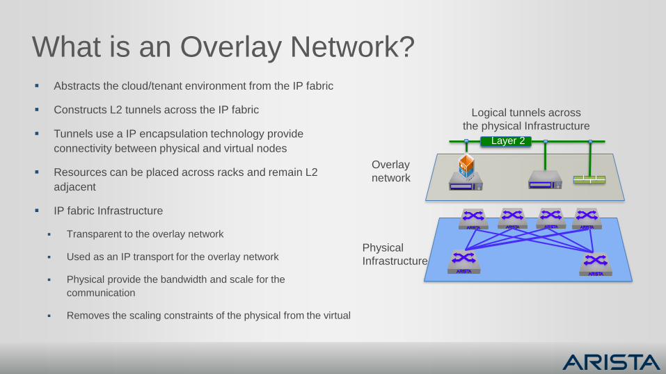
What is an Overlay Network? Abstracts the cloud/tenant environment from the IP fabric
Constructs L2 tunnels across the IP fabric
Tunnels use a IP encapsulation technology provide
connectivity between physical and virtual nodes
Resources can be placed across racks and remain L2
adjacent
IP fabric Infrastructure
Transparent to the overlay network
Used as an IP transport for the overlay network
Physical provide the bandwidth and scale for the
communication
Removes the scaling constraints of the physical from the virtual
Physical
Infrastructure
Overlay
network
Logical tunnels across
the physical Infrastructure
Layer 2
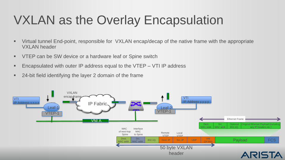
VXLAN as the Overlay Encapsulation
Virtual tunnel End-point, responsible for VXLAN encap/decap of the native frame with the appropriate VXLAN header
VTEP can be SW device or a hardware leaf or Spine switch
Encapsulated with outer IP address equal to the VTEP – VTI IP address
24-bit field identifying the layer 2 domain of the frame
Src.
MAC addr.
Dest.
MAC addr.802.1Q. Dest. IP Src. IP UDP
VNI
(24 bits) Payload FCS
Src.
MAC addr.
Dest.
MAC addr.
Optional
802.1Q.
Original Ethernet Payload (including
any IP headers etc.)
Ethernet Frame
Remote
VTEPLocal
VTEP
Interface
MAC
to Spine
MAC
of next-hop
Spine
50 byte VXLAN
header
VTEP
VTI
IP Address x.x.x.x
VNI A
IP Fabric
VTI
IP Address y.y.y.y
Leaf-1
VTEP-1
Leaf-2VTEP-1
VXLAN
encap frame
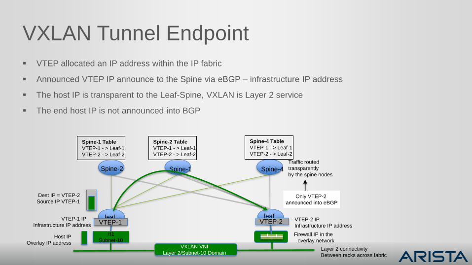
VXLAN Tunnel Endpoint
VTEP allocated an IP address within the IP fabric
Announced VTEP IP announce to the Spine via eBGP – infrastructure IP address
The host IP is transparent to the Leaf-Spine, VXLAN is Layer 2 service
The end host IP is not announced into BGP
leaf
Spine-2 Spine-1 Spine-4
leaf
H1
Subnet-10
VTEP-2VTEP-1
VXLAN VNI
Layer 2/Subnet-10 Domain
Traffic routed
transparently
by the spine nodes
Layer 2 connectivity
Between racks across fabric
VTEP-2 IP
Infrastructure IP address
VTEP-1 IP
Infrastructure IP address
Spine-1 Table
VTEP-1 - > Leaf-1
VTEP-2 - > Leaf-2
Dest IP = VTEP-2
Source IP VTEP-1
Spine-2 Table
VTEP-1 - > Leaf-1
VTEP-2 - > Leaf-2
Spine-4 Table
VTEP-1 - > Leaf-1
VTEP-2 - > Leaf-2
Host IP
Overlay IP address
Firewall IP in the
overlay network
Only VTEP-2
announced into eBGP
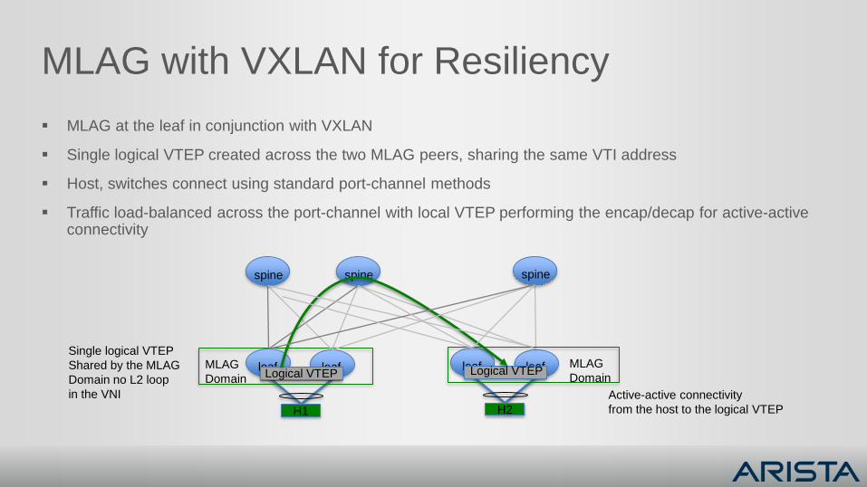
MLAG with VXLAN for Resiliency
MLAG at the leaf in conjunction with VXLAN
Single logical VTEP created across the two MLAG peers, sharing the same VTI address
Host, switches connect using standard port-channel methods
Traffic load-balanced across the port-channel with local VTEP performing the encap/decap for active-active connectivity
leaf leaf
spine spine spine
leaf leafLogical VTEP
H1
MLAG
DomainLogical VTEP
H2
MLAG
Domain
Active-active connectivity
from the host to the logical VTEP
Single logical VTEP
Shared by the MLAG
Domain no L2 loop
in the VNI
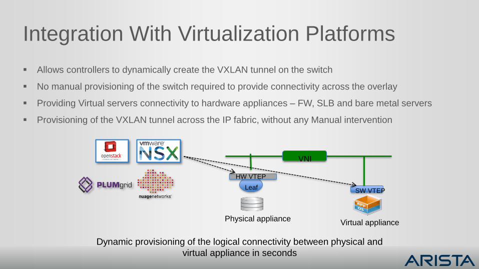
Integration With Virtualization Platforms
Allows controllers to dynamically create the VXLAN tunnel on the switch
No manual provisioning of the switch required to provide connectivity across the overlay
Providing Virtual servers connectivity to hardware appliances – FW, SLB and bare metal servers
Provisioning of the VXLAN tunnel across the IP fabric, without any Manual intervention
Dynamic provisioning of the logical connectivity between physical and
virtual appliance in seconds
SW VTEP
HW VTEP
Leaf
VNI
Physical applianceVirtual appliance
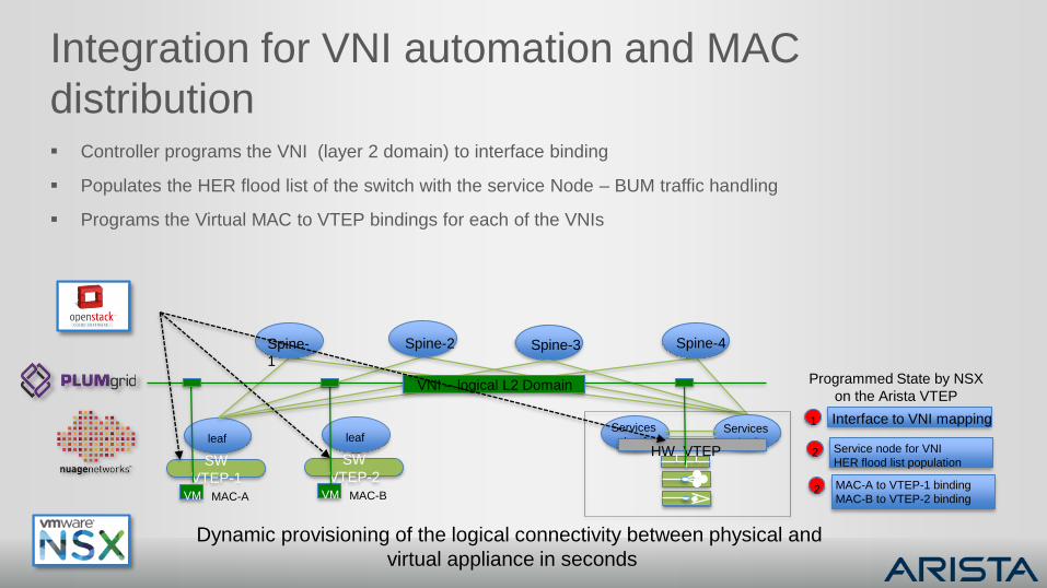
Integration for VNI automation and MAC
distribution Controller programs the VNI (layer 2 domain) to interface binding
Populates the HER flood list of the switch with the service Node – BUM traffic handling
Programs the Virtual MAC to VTEP bindings for each of the VNIs
Spine-2
leaf
Spine-3Spine-
1
Spine-4
SW
VTEP-1
Services
LeafServices
leaf
VM MAC-A
HW VTEPleaf
SW
VTEP-2VM MAC-B
VNI – logical L2 Domain Programmed State by NSX
on the Arista VTEP
Interface to VNI mapping1
Service node for VNI
HER flood list population2
MAC-A to VTEP-1 binding
MAC-B to VTEP-2 binding2
Dynamic provisioning of the logical connectivity between physical and
virtual appliance in seconds
Summary
Leaf/Spine Clos architecture for consistent and deterministic east to west traffic flows
L3 logical topology, using open and mature protocols to simplify scale and easy operations
Routing at the Leaf layer to reduce the L2 fault domain
BGP the preferred routing protocol, for scale and control reasons
ECMP for load-balancing traffic across the multiple spines
Layer 2 adjacency between racks using VXLAN = MAC in IP encapsulation
Open API to allow easy integration and automation with third-party Network virtualization platforms
Automate Physical to virtual connectivity from a single click