89


L4-L7 Services Insertion Design and Deployment
Azeem Suleman, Sr. Architect, Insieme Business Unit
BRKACI-1102

• Introduction
• Services Insertion Overview
• Concepts and Terminology
• Design Scenario’s
• Deployment Snapshots
• Conclusion
Agenda

Challenges of Today’s L4-L7 Services Deployment
Router
Router
Switch
Load balancer
Firewall
Firewall
Servers
Configure Network to insert Firewall
Configure Load Balancer Network Parameters
Configure Network to insert Firewall
Configure Network to insert Firewall Configure Firewall Network Parameters
Configure Network to insert Firewall Configure Firewall Rules required by Application
Configure Network to insert Firewall Configure Load Balancer Network Parameter
Configure Network to insert Firewall Configure Router to steer traffic to/from LB
Configure Network to insert Firewall Configure Load Balancer as required by application
Service insertion takes days. Network configuration is time
consuming and error prone.
Difficult to track configuration on services
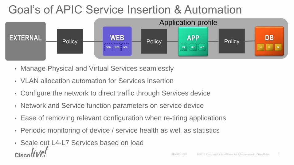
Goal’s of APIC Service Insertion & AutomationConfigure Network to insert Firewall
Configure Load Balancer Network Parameters
Configure Load Balancer as required by the application
APP DBWEBEXTERNAL
Application profile
PolicyPolicyPolicy
• Manage Physical and Virtual Services seamlessly
• VLAN allocation automation for Services Insertion
• Configure the network to direct traffic through Services device
• Network and Service function parameters on service device
• Ease of removing relevant configuration when re-tiring applications
• Periodic monitoring of device / service health as well as statistics
• Scale out L4-L7 Services based on load

Services Insertion Overview

ACI Nomenclature
Service Producers EPG “Users”EPG “Files”
Leaf Nodes
Spine Nodes
EPG “Internet”
AVS
Service Consumers

Services Insertion
WEBEXTERNAL Consumes Web Contract
HTTP: Accept, Service Graph
FW LB
Consumer Provider
• Contract provides a mechanism to add Network Services through associating a Services Graph
• A Services Graph identifies a set of service functions required by an application
• APIC configures service functions on the device like firewall, load balancers
• A device package can uploaded on APIC at run time
• Adding new service support through device package doesn’t require APIC reboot

Services Insertion Integration
1. Network and Service configuration on devices
2. Network configuration (Device Manager / Central Manager used for Service configuration)
3. No configuration on device

Services Insertion ArchitectureDevice Package
Configuration Model (XML File)
Python Scripts
Configuration Model
Device Interface: REST/CLI
APIC Script Interface
Python Scripts
Script Engine
APIC– Policy Manager
Service Device
APIC
• Service functions are added to APIC through device package
• Device Package contains a device model and device python scripts
• Device Model defines Service Function and Configuration
• Device scripts translates APIC API callouts to device specific callouts
• Script can interface with the device using REST, SSH or any mechanism

F5 BIG-IP and BIG-IQ Integration model with APIC
ACI Fabric Virtual Edition Appliance Chassis
BIG-IQ Device Packag
e
Device Packag
e
F5 Device Package Release 1.2 Deployment Model
BIG-IQ Integration with Cisco ACI
1
2
4a
BIG-IQ integration with APIC
1 - BIG-IP expose iApps to BIG-IQ
2 - BIG-IQ create custom device package
3 - Admin import BIG-IQ device package to APIC
4a - APIC sends iApp config to BIG-IQ -> BIG-IP
4b - APIC sends Device config to BIG-IP
BIG-IP integration with APIC
1 - Download device package from F5
2 - Admin import device package to APIC
3 - APIC sends config to BIG-IP directly
downloads.f5.com
3
32
4b
1
F5
Syn
the
sis
Fa
bric
Device Package
F5
Configuration{'state': 1, 'transaction': 0,
'ackedState': 0, 'value': {(5,
'DestinationNetmask',
'Netmask1'): {'state': 1,
'transaction': 0, 'ackedState':
0, 'value': '255.255.255.255'},
(5, 'DestinationPort',
'port1'): {'state': 1,
'transaction': 0, 'ackedState':
0, 'value': '80'
BIG-IQ Device
PackageF5 iApps
Config{'state': 1, 'transaction': 0,
'ackedState': 0, 'value': {(5,
'DestinationNetmask',
'Netmask1'): {'state': 1,
'transaction': 0, 'ackedState':
0, 'value': '255.255.255.255'},
(5, 'DestinationPort',
'port1'): {'state': 1,
'transaction': 0, 'ackedState':
0, 'value': '80'
F5 Device
Config{'state': 1, 'transaction': 0,
'ackedState': 0, 'value': {(5,
'DestinationNetmask',
'Netmask1'): {'state': 1,
'transaction': 0, 'ackedState':
0, 'value': '255.255.255.255'},
(5, 'DestinationPort',
'port1'): {'state': 1,
'transaction': 0, 'ackedState':
0, 'value': '80'

Concepts and Terminology

Concepts – Services Graph• Ordered set of network or service functions that are needed by the application.
• Service functions within a graph are automatically provisioned on a service device that is based on application’s requirements.
Function Firewall
Function SSL offload
Function Load Balancer
Terminal Terminal
Firewall parametersPermit ip tcp * dest-ip <vip> dest-port 80Deny ip udp *
Load-Balancer parametersVirtual-ip <vip>Port 80 LB-algorithm: round-robin
SSL paramsIpaddress <vip> port 80
Connectors
Service Graph: “web-application”
Consumer Provider

Concepts – Rendering a Services Graph• APIC picks a logical
device from an Admin specified group of devices.
• Resolves configuration parameters & prepares configuration dictionary
FunctionFirewall
FunctionSSL offload
FunctionLoad Balancer
Service Graph: “web-application”
FirewallFunction SSL offload
FunctionLoad Balancer
Allocate & configure VLAN
EXTERNAL WEB
• Allocates VLANs for each connectors associated with the function
• Provisions the network (VLAN), EPGs and appropriate whitelist entries on leaf(s)
• APIC makes script calls to configuration the service device with appropriate information
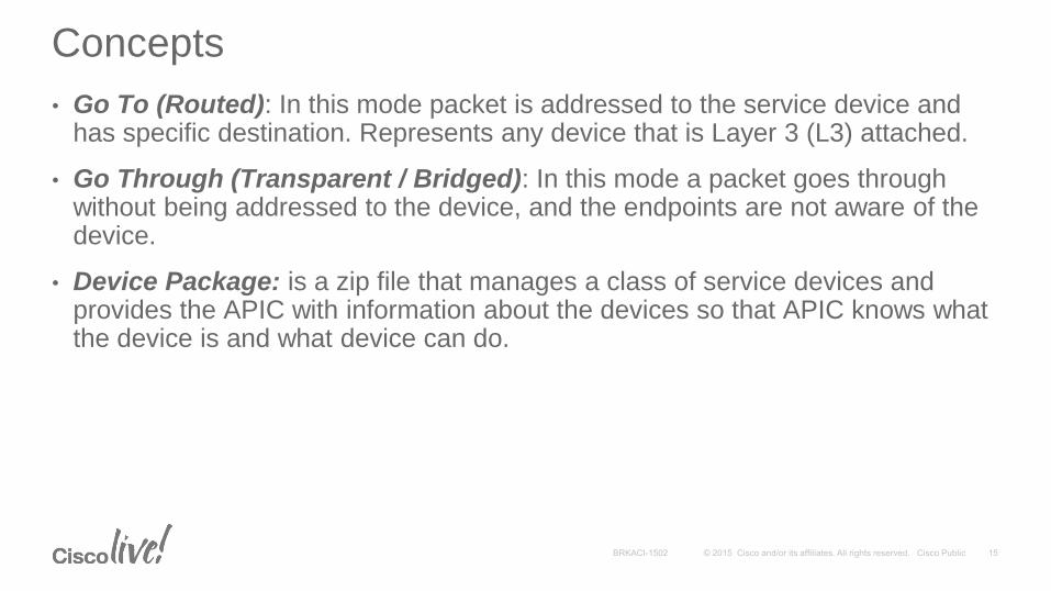
Concepts
• Go To (Routed): In this mode packet is addressed to the service device and has specific destination. Represents any device that is Layer 3 (L3) attached.
• Go Through (Transparent / Bridged): In this mode a packet goes through without being addressed to the device, and the endpoints are not aware of the device.
• Device Package: is a zip file that manages a class of service devices and provides the APIC with information about the devices so that APIC knows what the device is and what device can do.

Terminology• Function Profile: Profile contains all the configurable parameters supported
by the device vendor organized into folders
• Terminal Nodes: connects a service graph with the contracts.
• Concrete Device: Represents an actual service device e.g. one Load Balancer or one Firewall
• Logical Device / Device Cluster: Managed through a management IP address that is assigned to the cluster. A cluster of 2 devices that operate in either active / active or active / standby mode for instance
• Logical Device Context: Specifies upon which criteria a specific device in the inventory should be used to render a service graph
• Connections: How traffic is forwarded through the network

Design Scenario’s

Firewall as Transparent (Go Through)
inside interface
VLAN 1001
outside interface
VLAN 1002
VLAN
Translation
SVI 1002
VIP
VLAN 1001
IP: 10.10.10.10
IP: 10.10.10.1• VLAN translation between VLAN 1001 and VLAN
1002
• Default gateway for servers on VLAN 1001
• Defined on next hop router
• VIP defined on SVI 1002
• Hosts are on same ip subnets for inside and outside ports
• Acts as “bump in a wire”

Firewall as Transparent (Go Through)
Client EPG
Server EPG
FW
Graph A 10.0.0.0/24
Tenant A
External Internal
Hardware
Proxy
ARP
Flooding
Unknown
Unicast
Flooding
Unicast
Routing
Subnet (Default
Gateway
Configuration)
Association with
VRF Instance
Client-Side
Bridge
Domain
Yes No No Yes
Yes (default
gateway for
servers)
Yes
Server-Side
Bridge
Domain
No Yes Yes No NoYes (but not
used)
* Silent hosts require flooding on both sides

Firewall as Routed (Go To)
Client EPG
ServerEPG
FW
Graph A10.0.0.0/24 10.0.0.1 20.0.0.1 20.0.0.0/24
Tenant A
External Internal
Hardware
Proxy
ARP
Flooding
Unknown
Unicast
Flooding
Unicast
Routing
Subnet (Default
Gateway
Configuration)
Association with
VRF Instance
Client-Side
Bridge
Domain
No Yes Yes No No Yes
Server-Side
Bridge
Domain
No Yes Yes No NoYes (but not
used)
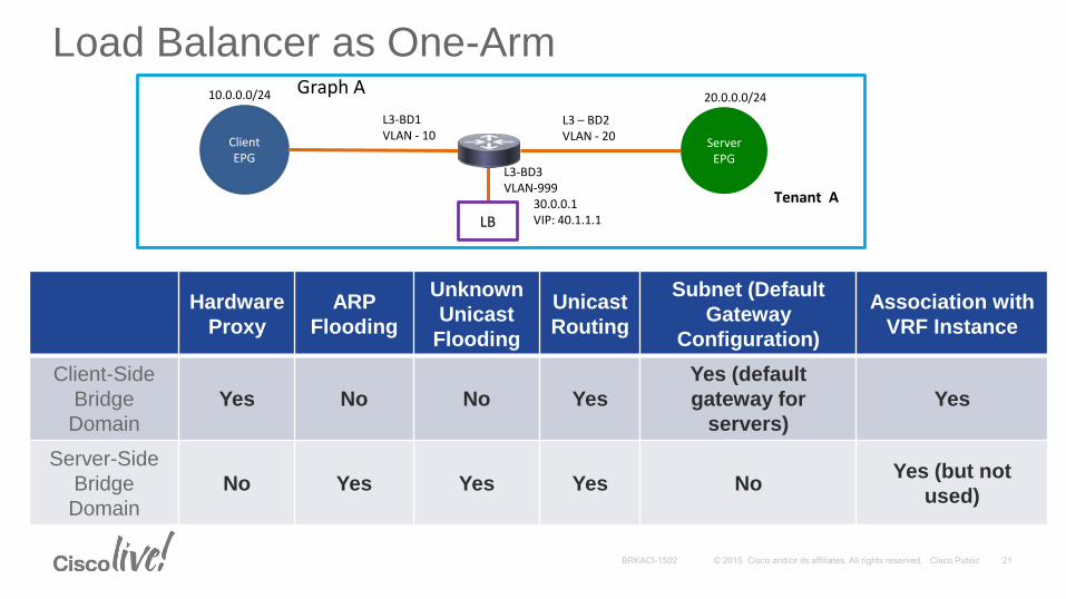
Load Balancer as One-Arm
Hardware
Proxy
ARP
Flooding
Unknown
Unicast
Flooding
Unicast
Routing
Subnet (Default
Gateway
Configuration)
Association with
VRF Instance
Client-Side
Bridge
Domain
Yes No No Yes
Yes (default
gateway for
servers)
Yes
Server-Side
Bridge
Domain
No Yes Yes Yes NoYes (but not
used)
Client EPG
ServerEPG
Graph A10.0.0.0/24
L3-BD1VLAN - 10
L3 – BD2VLAN - 20
20.0.0.0/24
Tenant A
LB30.0.0.1VIP: 40.1.1.1
L3-BD3VLAN-999

Load Balancer as Two-Arm
Hardware
Proxy
ARP
Flooding
Unknown
Unicast
Flooding
Unicast
Routing
Subnet (Default
Gateway
Configuration)
Association with
VRF Instance
Client-Side
Bridge
Domain
Yes No No Yes
Yes (default
gateway for
servers)
Yes
Server-Side
Bridge
Domain
No Yes Yes * No NoYes (but not
used)
Client EPG
ServerEPG
LB
Graph A10.0.0.0/24 10.0.0.1 20.0.0.1 20.0.0.0/24
Tenant A
External Internal
* If SNAT is done, routing can be enabled and flooding disabled

L4-L7 Design update in B-release (FCS+9)
New Features:
• L4-L7 Route Peering
• Shared Device and Bridge Domain (BD)
• ACI Fabric with IPv6 support
• Dynamic Attach Endpoint
• Device Package support matrix.
Route Peering IPv6 Interface NAT64, NAT46
ASA Yes Yes Yes
Citrix Yes Yes Yes
F5 No No No

L4-L7 Route Peering

L4-L7 Route Peering
• With “fabric as a transit” use case, in which route peering enables the ACI Fabric to serve as a transit OSPF or BGP domain for other points of delivery (PODs).
• A common use case for route peering is RHI (route health injection), in which the server load balancing virtual IP is advertised over dynamic routing protocol e.g. OSPF or iBGP to clients that are outside of the ACI Fabric.
• Route peering is used to configure OSPF or BGP peering on a Layer4 to Layer 7 service device so that the device can peer and exchange routes with the ACI leaf node to which it is connected.
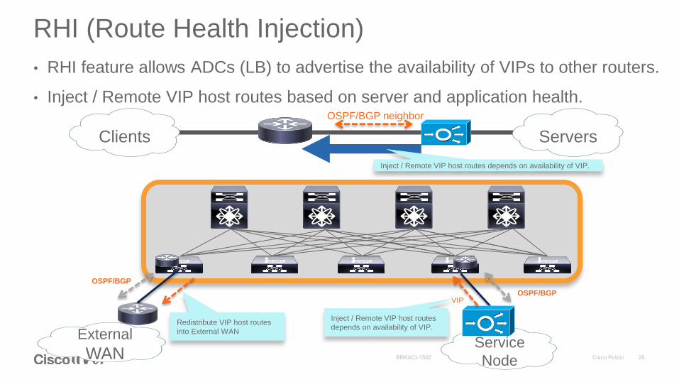
RHI (Route Health Injection)
• RHI feature allows ADCs (LB) to advertise the availability of VIPs to other routers.
• Inject / Remote VIP host routes based on server and application health.
Clients Servers
OSPF/BGP neighbor
Inject / Remote VIP host routes depends on availability of VIP.
External
WAN
OSPF/BGP
Redistribute VIP host routes
into External WAN
Service
Node
OSPF/BGPVIP
Inject / Remote VIP host routes
depends on availability of VIP.

L4-L7 Route Peering with ASA
EPGWeb
ext int
VRF2
10.10.10.200/24
VRF1
30.30.30.0/2440.40.40.0/24
Loopback
200.200.200.200
Source: 20.20.20.200/24
Destination: 10.10.10.200/24
Need to know
10.10.10.0/24 route
10.10.10.0/24
Need to know
20.20.20.0/24 route
20.20.20.0/24
.254.203.101.101
.201
20.20.20.203/24
Loopback
200.200.200.200
10.10.10.200/24

L4-L7 Route Peering with Citrix
EPGWeb
ext int
VRF2
10.10.10.200/24
VRF1
30.30.30.0/2440.40.40.0/24
Loopback
200.200.200.200
Source: 20.20.20.200/24
Destination: 40.40.40.100 (VIP)
10.10.10.0/2420.20.20.0/24
.254.203
.101.101
.201VIP: 100
Source: 30.30.30.101/24
Destination: 10.10.10.200
20.20.20.203/24
Loopback
200.200.200.200
10.10.10.200/24

Shared Device and Bridge Domain
Contract
(Service Graph A)
ProvideConsume
EPGProvider
10.10.10.10/24
EPGConsumer
Contract
(Service Graph B)
Provide EPGProvider
20.20.20.0/24
30.30.30.0/24
.1
.1Tenant B
tn-common / tn-mgmt
Tenant A
EPGConsumer
10.10.10.10/24 20.20.20.0/24
30.30.30.0/24
.1
.1
10.10.10.1
EPGProvider
EPGProvider
VLAN 10
VLAN 20
VLAN 30
Share same concrete device
in tn-common/tn-mgmt by
multiple tenant.
.1 *BDs have to be in tn-common

Dynamic Attach Endpoint
• APIC provides endpoint notification to the script through API callouts. This will help dynamically detect new endpoint, then the endpoint is automatically added to the pool member of VIP
EPGConsumer
EPGProvider
20.20.20.1
VIP: 10.10.10.200
20.20.20.100/2410.10.10.100/24
Web-Pool
20.20.20.2
New
20.20.20.3
New

IPv6 Support• In B-release, ACI Fabric supports IPv6
• ASA and Citrix Device Package support IPv6 interface and NAT64/NAT46.
• Tested Scenario:
• NAT64 and NAT46
• ASA: 1:1 Static NAT only
Consumer
V6 V4
FW ADC
NAT64
on ADCProvider
Consumer
V6
FW ADC
IPv6
only Provider

IPv6 Support (Cont.)
Consumer Provider
V6 V4
FW ADC
NAT64
on FW
Consumer
V4 V6
FW ADC
NAT46
on ADC Provider
Consumer
V4 V6
FW ADC
NAT46
on FWProvider

L4-L7 Services InsertionData Path

Physical Topology
1/4
Node: 104 (leaf 1)Node: 105 (leaf 2) Node: 106 (leaf 3)
1/201/10
10/1 10/2Gig 1/17
1/06
Gig 1/18
C1
Client Server VMs
ESXi
UCS220
Firewall
Load BalancerASA 5585-20
1/5
UCS220
Web Server VMs
10.0.0.3
Node: 107 (leaf 4)
w1
10.0.0.4
1/45
30.0.0.3 30.0.0.4
w2C2

Desired Network Topology
c110.0.0.3
10.0.0.4
w1 20.0.0.3
20.0.0.4
FirewallLoad
Balancer
10.0.0.0/24 30.0.0.0/2420.0.0.0/28
VIP: 40.0.0.1
RouterRouter
VRF 2VRF 1
w2c2

Policy and Graph Configuration
Client
EPGWeb
EPG
Contract: web
subject: http
filter: match http(80) action allow
graph: webGraph
subject: icmp
Filter match proto: icmp action allow
ProviderConsumer
FW LB
External
ConnectorGo-To Go-To
VIP: 40.0.0.1
Internal
ConnectorExternal
Connector
Internal
Connector
20.0.0.0/28
20.0.0.2/28 20.0.0.3/28
BD1 BD2BD3
VRF1
Subnet 20.0.0.1/28Subnet: 10.0.0.1/24
Subnet 30.0.0.1/24
webGraph
10.0.0.2/2430.0.0.2/24
VLAN 3000VLAN 2000

Service Graph: Dynamically provisioned EPGs
Client
EPG
Web
EPG
FW LB
External
Connector
Go-To Go-To
VIP: 40.0.0.1
Internal
Connector
External
Connector
Internal
Connector
20.0.0.0/28
20.0.0.2/28 20.0.0.3/28
BD1 BD2BD3
VRF2
Subnet 20.0.0.1/28Subnet: 10.0.0.1/24
Subnet 30.0.0.1/24
webGraph
10.0.0.2/24 30.0.0.2/24
FW
EPG
Ext
FW
EPG
Int
LB EPG
Ext
LB EPG
Int
APIC dynamically creates EPGs for each connector and allocates VLAN encap
VLAN 3000VLAN 2000
VLAN 1500 VLAN 1501 VLAN 1601 VLAN 1602
VRF1

Contract Enforcement
• Contract: web, subject: http is enforced between EPG1 and dynamically created EPG FW Ext
• No contract is enforced after service device – All traffic is permitted betweeno Dynamically created EPG FW Int and dynamically created LB EPG Ext
o Dynamically created EPG LB Int and EGP2
Client
EPG Web
EPG
BD1 BD2BD3
VRF1
Subnet 20.0.0.1/28
Subnet: 10.0.0.1/24 Subnet 30.0.0.1/24
FW
EPG
Ext
FW
EPG
Int
LB EPG
Ext
LB EPG
Int
VLAN 3000VLAN 2000
Contract: web
subject: http
filter: match http(80) action allow
Contract: web
subject: icmp
filter: match proto icmp action allow
VRF2

Device and Interface Selection
LB
Node
ProviderConsumer
Connector: External Connector: Internal
LIF Outside LIF Inside
Device Cluster: NS_cluster_1
LB-1
LB-2
10/2 10/2
WebGraph
Device Selection logic:
<vnsLDevCtx ctrctNameOrLbl="web graphNameOrLbl=“webGraph" nodeNameOrLbl=“FW">
<vnsRsLDevCtxToLDev tDn="uni/tn-Tenant1/lDevVip-FWCluster1"/>
</vnsLDevCtx>
Map Connector to Logical Interface:
<vnsLIfCtx connNameOrLbl=“Internal">
<fvSubnet ip=“20.0.0.1/24"/>
<vnsRsLIfCtxToLIf tDn="uni/tn-Tenant1/lDevVip-FWCluster1/lIf-internal"/>
</vnsLIfCtx>
<vnsLIfCtx connNameOrLbl=“External">
<fvSubnet ip="10.0.0.1/24" />
<vnsRsLIfCtxToLIf tDn="uni/tn-Tenant1/lDevVip-FWCluster1/lIf-external"/>
</vnsLIfCtx>
Map Logical Interface to device physical interface:
<vnsLDevVip name=“FWCluster1">
<vnsLIf name=“Internal">
<vnsRsMetaIf tDn="uni/infra/mDev-CISCO-ASA-1.0/mIfLbl-Internal"/>
<vnsRsCIfAtt tDn="uni/tn-Tenant1/lDevVip-FWCluster1/cDev-FW1/cIf-[gig1/0]"/>
</vnsLIf>
<vnsLIf name=“External">
<vnsRsMetaIf tDn="uni/infra/mDev-CISCO-ASA-1.0/mIfLbl-External"/>
<vnsRsCIfAtt tDn="uni/tn-Tenant1/lDevVip-FWCluster1/cDev-FW1/cIf-[gig1/1]"/>
</vnsLIf>
</vnsLDevVip>
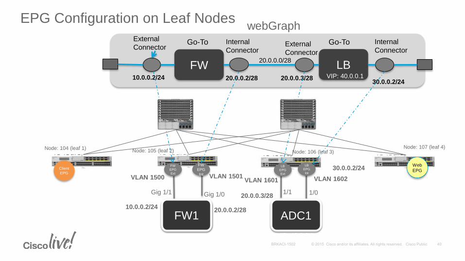
EPG Configuration on Leaf Nodes webGraph
ADC1FW1
FW
EPG
Ext
FW
EPG
Int
LB
EPG
Ext
LB
EPG
Int
Gig 1/1 Gig 1/0 1/1 1/0
10.0.0.2/24
30.0.0.2/24
20.0.0.3/28
20.0.0.2/28
VLAN 1500 VLAN 1501VLAN 1601 VLAN 1602
VIP: 40.0.0.1
ADC1FW1
FW LB
External
ConnectorGo-To Go-To
VIP: 40.0.0.1
Internal
ConnectorExternal
Connector
Internal
Connector
20.0.0.0/28
20.0.0.2/28 20.0.0.3/2810.0.0.2/2430.0.0.2/24
Client
EPG
Web
EPG
Node: 104 (leaf 1)Node: 105 (leaf 2) Node: 106 (leaf 3)
Node: 107 (leaf 4)
VIP: 40.0.0.1

Data Path configuration on leaf Node 1BD, S_Class derivation:
Vlan 3000: s_class = Client EPG, BD1, VRF1
L2 Table:<BD1, FW_MAC> : NH: Leaf 2 VTEP, D_class: FW_ext
<BD1, Client 1>: NH: 1/1, D_class: Client EPG
<BD1, Client 2>: NH: 1/2, D_class: Client EPG
L3 Table:<vrf1, 10.0.0.3/32>: NH: Client 1 MAC, 1/1, d_class: FW_ext
<vrf1, 10.0.0.4/32>: NH: Client 2 MAC, 1/2, d_class: FW_ext
<vrf1, 10.0.0.2/32>: NH: FW1 MAC, Leaf 2 VTEP, d_class: FW_ext
<vrf1, 20.0.0.0/28>: NH: FW1 MAC, Leaf 2 VTEP, d_class: FW_ext
<vrf1, 40.0.0.1/32>: NH: FW1 MAC, Leaf 2 VTEP, d_Class: FW_ext
Policy: s_class: Client EPG, d_class: FW_ext, http : permit
s_class: Client EPG, d_class: Web EPG, icmp: permit

Data Path configuration on leaf Node 2BD, S_Class derivation:
VLAN 1500: s_class: FW_ext, BD 2, VRF 1
VLAN 1501: s_class: FW_int, BD 3, VRF 2
L2 Table:<BD1, FW MAC> : NH: 1/10, d_class: FW_ext
<BD3, FW MAC> : NH: 1/20, d_class: FW_int
<BD2, LB_MAC> : NH: Leaf 3 VTEP, d_class: LB_ext
L3 Table:<vrf1, 10.0.0.2/32>: NH: FW1 MAC, 1/10, d_class: FW_ext
<vrf1, 10.0.0.3/32>: NH: FW1 MAC, Leaf 1 VTEP, d_class: Client EPG
<vrf1, 10.0.0.4/32>: NH: FW1 MAC, Leaf 1 VTEP, d_class: Client EPG
<vrf1, 20.0.0.0/28>: NH: FW1 MAC, 1/10, d_class: FW_ext
<vrf1, 40.0.0.1/32>: NH: FW1 MAC, 1/10, d_class: FW_ext
<vrf2, 10.0.0.0/24>: NH: FW1 MAC, Leaf 1 VTEP, d_class: FW_ext
<vrf2, 20.0.0.2/32>: NH: FW1 MAC, 1/20, d_class: FW_int
<vrf2, 20.0.0.3/32>: NH: LB MAC, Leaf 3 VTEP, d_class: LB_ext
<vrf2, 40.0.0.1/32>: NH: LB MAC, leaf 3 VTEP, d_Class: LB_ext
<vrf2, 30.0.0.2/24>: NH: LB MAC, Leaf 3 VTEP, d_class: LB_ext
Policy: s_class: Client EPG, d_class: FW_ext, http : permit
s_class: FW_int, d_class: LB_ext, * : permit

Data Path configuration on leaf Node 3BD, S_Class derivation:
VLAN 1601: s_class: LB_ext, BD 2, VRF 2
VLAN 1602: s_class: LB_int, BD 3, VRF 2
L2 Table:<BD2, FW_MAC> : NH: Leaf 2 VTEP, d_class: FW_int
<BD2, LB_MAC> : NH: 1/30, d_class: LB_ext
<BD3, LB_MAC> : NH: 1/40, d_class: LB_int
L3 Table:<vrf2, 10.0.0.0/24>: NH: FW1 MAC, Leaf 2 VTEP, d_class: FW_ext
<vrf2, 20.0.0.2/32>: NH: FW1 MAC, Leaf 2 VTEP, d_class: FW_int
<vrf2, 20.0.0.3/32>: NH: LB MAC, 1/30, d_class: LB_ext
<vrf2, 40.0.0.1/32>: NH: LB MAC, 1/30, d_Class: LB_ext
<vrf2, 30.0.0.2/32>: NH: LB MAC, 1/40, d_class: LB_int
<vrf2, 30.0.0.3/32>: NH: LB MAC, Leaf 4 VTEP, d_class: Web EPG
<vrf2, 30.0.0.4/32>: NH: LB MAC, Leaf 4 VTEP, d_class: Web EPG
Policy: s_class: FW_int, d_class: LB_ext, * : permit
s_class: LB_int, d_class: Web EPG, * : permit

Data Path configuration on leaf Node 4
BD, S_Class derivation: VLAN 2000: s_class: Web EPG, BD 3, VRF 2
L2 Table:<BD2, LB_MAC> : NH: Leaf 3 VTEP, d_class: LB_int
<BD3, Web 1> : NH: 1/40, d_class: Web EPG
<BD3, Web 2> : NH: 1/41, d_class: Web EPG
L3 Table:<vrf2, 10.0.0.0/24>: NH: FW1 MAC, Leaf 2 VTEP, d_class: FW_ext
<vrf2, 20.0.0.2/32>: NH: FW1 MAC, Leaf 2 VTEP, d_class: FW_int
<vrf2, 20.0.0.3/32>: NH: LB MAC, Leaf 3 VTEP, d_class: LB_int
<vrf2, 30.0.0.4/32>: NH: LB MAC, 1/30, d_class: Web EPG
<vrf2, 30.0.0.3/32>: NH: LB MAC, 1/30, d_Class: Web EPG
<vrf2, 30.0.0.2/24>: NH: LB MAC, Leaf 3 VTEP, d_class: LB_int
Policy: s_class: LB_int, d_class: Web EPG, * : permit
s_class: Client EPG, d_class: Web EPG, ICMP : permit

Deployment Snapshots

Cisco ACI Architecture
Active Standby
External / Internal
External / Internal
1-ARM topology + HA pair
Active Standby
External
2-ARM topology + HA pair
Internal ExternalInternal
BIG-IP connects to any Leaf in ACI topology independent of Leaf
location

Services Insertion Configuration Wizard
Create L4-L7 Service Graph Template
Create L4-L7 Service Devices
Apply L4-L7 Service Graph Template to EPGs
Three step process and each can be re-used
1
2
3

Create a L4-7 Service Devices – Single Device
Name of the device
Specify Device Package to manage this Cluster
Model of the device
Login Credentials to manage the device and connectivity information
Policy domain
Device Management IP Address and port

Create a L4-7 Service Devices - HA
This shows how Wizard will look if you select HA Cluster

Create a L4-7 Service Devices – Device Package
List of device package that APIC has will be shown here

Create a L4-7 Service Devices – Model (Citrix)
Single device or cluster / HA
Associated interfaces on the device to interface labels

Create a L4-7 Service Devices – Connectivity (Citrix)
Management
connectivity to
the device

Create a L4-7 Service Devices – Connectivity (Citrix)
Device Parameter that
is required.

Create a L4-7 Service Devices – Connectivity (Citrix)
Shows all the
parameters

Create a L4-7 Service Graph Template
Templates gives you option to
choose simple Service Graph
based on your requirement

Create a L4-7 Service Graph Template – Single Node ADC
Device Package gives you an
option that you want to use for
the particular Services Graph
Profile will give the service
graph all the parameters that is
needed. E.g. SSL
Users can also customize the
profile. You can click on profile
to see what parameters are
available.

Apply L4-L7 Service Graph Template to EPGs
EPG and Service Graph
Template
If you uncheck “Allow All
Traffic” i.e. IP Any any or you
can create your own specific
filter entries

Apply L4-L7 Service Graph Template to EPGs

L4-L7 Route Peering

L4-L7 Route Peering with ASA (Physical)
Configure VRF, Bridge Domain, EPG and Service Graph as usual
1. Make sure Adjacency type is L3.
2. Create static VLAN pool and External Routed Domain
3. Create Route Tag Policy
4. Create L3Out
5. Change Devices Selection Policies setting
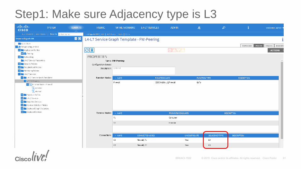
Step1: Make sure Adjacency type is L3

Step2: Create static VLAN pool & External Routed Domain
• Create a static VLAN pool that will be used for the encap VLAN between L4-L7 device and fabric

Step3: Create Route Tag Policy
• Every context (VRF) used by route peering needs a unique route tag to avoid OSPF loops.

Step3: Create Route Tag Policy (Cont.)

Step4: Create L3Out – ASA External
Create L3Out for routing
between Leaf and L4-L7 device.
Set External Routed Domain which
contains VLAN Pool for encap ID
between Leaf and L4-L7 device.

Step4: Create L3Out – ASA Internal
Create L3Out for routing
between Leaf and L4-L7 device.
Set External Routed Domain which
contains VLAN Pool for encap ID
between Leaf and L4-L7 device.

L4-L7 Route Peering with Citrix (Virtual)
Configure VRF, Bridge Domain, EPG and Service Graph as usual
1. Make sure Adjacency type is L3.
2. Create static VLAN pool and External Routed Domain
3. Create Route Tag Policy
4. Create L3Out
5. Change Devices Selection Policies setting
Shared Device with ASA (Physical)

Shared Device and Bridge Domain
EPGConsumer
• Server A needs to connect provider EPGs in multiple tenants via ASA, but customer don’t want to deploy FW/ASA context per tenant.
EPGProvider
EPGProvider
Tenant B
Tenant A20.20.20.100/24
30.30.30.100/24
Source: A
Destination: 20.20.20.100
Server A
Source: A
Destination: 30.30.30.100
10.10.10.1
20.20.20.1
30.30.30.1
*We can use this feature not only with ASA, but also other service appliances(F5, Citrix)

Steps
1. Create BDs in tn-common
2. Create concrete device in tn-common
3. Create Contract with Global scope in user tenant
4. Create Service Graph in user tenant
5. Device Selection Policy in user tenant
6. Deploy Service Graph in user tenant

Step1: Create Bridge Domain in Tenant Common
EPGConsumer
.1
.1
10.10.10.1
EPGProvider
EPGProvider
Common-BD3Common-BD1
Common-BD2

Step2: Create Concrete Device in Tenant Common
Physical domain with
dynamic VLAN pool
ASA5585 user
context mgmt IP
ASA5585 system
context mgmt IP

Step3: Create Contract with Global Scope in User Tenant
Scope: Global Export to tenant including
consumer EPG

Step4: Create Service Graph in User Tenant

Step5: Device Selection Policy in User Tenant
Select concrete
device in tn-common
Select BD in tn-common

Step5: Device Selection Policy in User Tenant (Cont.)
Select BD in tn-common
Select same BD for
external side.

Step6: Deploy Service Graph in User Tenant

Deployed Graph Instance in User Tenant
Encap of external
connector is same.Encap for external
connector is same.

Deployed Devices in Tenant Common
Deployed Device is showed up
in tn-common, not user tenant
EPGConsumer
10.10.10.10/24 20.20.20.0/24
30.30.30.0/24
.1
.1
10.10.10.1
EPGProvider
EPGProvider
VLAN 624
VLAN 625
VLAN 618

ASA Configuration
ciscoasa/mihiguch-common# show run
<snip>
interface GigabitEthernet0/2.618
nameif externalIf-T1
security-level 0
ip address 10.10.10.1 255.255.255.0
!
interface GigabitEthernet0/2.624
nameif internalIf-T1
security-level 100
ip address 20.20.20.1 255.255.255.0
!
interface GigabitEthernet0/2.625
nameif internalIf-T2
security-level 100
ip address 30.30.30.1 255.255.255.0
### ASA5585 system context ###
ciscoasa# show run context mihiguch-common
context mihiguch-common
allocate-interface GigabitEthernet0/2.618
allocate-interface GigabitEthernet0/2.624-GigabitEthernet0/2.625
allocate-interface Management0/0
config-url disk0:/mihiguch-common.cfg
APIC add allocate-interface
configuration with dynamically
assigned VLAN from VLAN pool
EPGConsumer
10.10.10.10/24 20.20.20.0/24
30.30.30.0/24
.1
.1
10.10.10.1
EPGProvider
EPGProvider
VLAN 624
VLAN 625
VLAN 618

Dynamic Attach Endpoint

Dynamic Attach Endpoint - Configuration
• Check “Attachment Notification” on Function Connector under Service Graph template

APIC debug.log
• Locate the APIC that contains the shard configuring the BIG-IP, then go to the following location
admin@apic1:~> cd /data/devicescript/F5.BIGIP.1.0.0/logs
• You will see debug.log and periodic.log
admin@apic1:logs> ls –all
• You can “tail –f debug.log” to monitor the process

References
• F5 BIG-IP: Workload Migration from Traditional Networks to Cisco ACI http://www.cisco.com/c/dam/en/us/solutions/collateral/data-center-virtualization/application-centric-
infrastructure/guide-c07-733816.pdf
• F5 and Cisco ACI: Solution Profilehttp://www.f5.com/pdf/solution-profiles/cisco-aci-f5-synthesis-solution-profile.pdf
• Cisco ACI Whitepapershttp://www.cisco.com/c/en/us/solutions/data-center-virtualization/application-centric-infrastructure/white-
paper-listing.html

Participate in the “My Favorite Speaker” Contest
• Promote your favorite speaker through Twitter and you could win $200 of Cisco Press products (@CiscoPress)
• Send a tweet and include
• Your favorite speaker’s Twitter handle azeem_suleman
• Two hashtags: #CLUS #MyFavoriteSpeaker
• You can submit an entry for more than one of your “favorite” speakers
• Don’t forget to follow @CiscoLive and @CiscoPress
• View the official rules at http://bit.ly/CLUSwin
Promote Your Favorite Speaker and You Could Be a Winner

Complete Your Online Session Evaluation
Don’t forget: Cisco Live sessions will be available for viewing on-demand after the event at CiscoLive.com/Online
• Give us your feedback to be entered into a Daily Survey Drawing. A daily winner will receive a $750 Amazon gift card.
• Complete your session surveys though the Cisco Live mobile app or your computer on Cisco Live Connect.

Continue Your Education
• Demos in the Cisco campus
• Walk-in Self-Paced Labs
• Table Topics
• Meet the Engineer 1:1 meetings
• Related sessions

Thank you


