UNCLASSIFIE SEURI CLAS IFICATION PAGE Form Approved REPORT DOCUMENTATION PAGE OmsNO. 07pp -0188 la. REPORT SECURITY CLASSIFICATION lb. RESTRICTIVE MARKINGS UNCLASSIFIED 2a. SECURITY CLASSIFICATION AUTHORITY 3 DISTRIBUTION/AVAILABILITY OF REPORT 2b. DECLASSIFICATIONIDOWNGRA3ING SCHEDULE Approved for Public Release; Distribution Unlimited. 4. PERFORMING ORGANIZATION REPORT NUMBER(S) S MONITORING ORGANIZATION REPORT NUMBER(S) BRL-MR- 3755 6a. NAME OF PERFORMING ORGANIZATION 6b. OFFICE SYMBOL 7a. NAME OF MONITORING ORGANIZATION US Army Ballistic Research Of aplicable) Labora tory ISLCBR-VL-V 6c. ADDRESS (City, State, and ZIP Code) 7b. ADDRESS (City, State, and ZIP Code) Aberdeen Proving Ground, MD 21005-5066 &a. NAME OF FUNDING/SPONSORING 8b. OFFICE SYMBOL 9. PROCUREMENT INSTRUMENT IDENTIFICATION NUMBER ORGANIZATION (If applicable) Sc. ADDRESS (City, State, and ZIP Code) 10. SOURCE OF FUNDING NUMBERS PROGRAM I PROJECT I TASK WORK UNIT ELEMENT NO, NO. NO. ,CCESSION NO. 11. TITLE (include Security Clasification) Computer Simulations of the Abrams Live-Fire Field Testing 12. PERSONAL AUTHOR(S) Deitz, Paul H. and Ozolins, Aivars 13a. TYPE OF REPORT 13b. TIME COVERED 14. DATE OF REPORT (Year, Month, Day) 15. PAGE COUNT Final FROM TO 16. SUPPLEMENTARY NOTATION Presented as a paper at the Army Operations Research Symposium XXVII, Ft. Lee Virginia, 12-13 October 1988. 17. COSATI CODES 18. SUBJECT TERMS (Continue on reverse if necessary and identify by block number) FIELD GROUP SUB-4ROUP Behind-Armor Debris Live-Fire Testing,BAL"'j _S " I Compartment Model,4" LA. Point-Burst Modeling('-E _ ,iCriticality Analysis, -q A ,\.H 19, AlPACT (Continue on reverse if necessary and identify by block number) Over the years the vulnerability community has developed an array of computer models to predict munition/target interactions. These models range in complexity from the so-called Compartment Model, in which interior behind- armor debris damage is treated by lumped parameters, to the highly detailed Point-Burst (or Component-Code) models in which these effects are assessed explicitly. Unfortunately neither type can provide truly useful modeling support for Live-Fire Testing. The fundamental difficulty here is that both types provid first-moment ore::,oected-vaiue estimates of vulnerability, whereas combat damage can be highly stochastip. Single-shot (unreplicated) Live-Fire test results are single realizations of many possible and varied outcomes. To compare first-moment values on/a shot-by-shot basis with single test samples can be a meaningless exercise. In addition, the Compartment Model lacks the necessary (Continued on reverse side) 20. DISTRIBUTION /AVAILABILITY OF ABSTRACT 21. ABSTRACT SECURITY CLASSIFICATION rUNCLASSIFIED/JNLIMITED M SAME AS RPT. [3 DTIC USERS UNCLASSIFIED Z2a. NAME OF RESPONSIBLE INDIVIDUAL 22b. TELEPHONE (Include Area Code) 22c. OFFICE SYMBOL Paul H. Deitz 301-278-6644 SLCBR-VL-V 00 Form 1473, JUN 86 Previous editions are obsolete. CASSIFIATION OF THIS PAGE U~tLb rh E U
2b. DECLASSIFICATIONIDOWNGRA3ING SCHEDULE Approved for Public Release; DistributionUnlimited.
4. PERFORMING ORGANIZATION REPORT NUMBER(S) S MONITORING ORGANIZATION REPORT NUMBER(S)
BRL-MR- 3755
6a. NAME OF PERFORMING ORGANIZATION 6b. OFFICE SYMBOL 7a. NAME OF MONITORING ORGANIZATIONUS Army Ballistic Research Of aplicable)Labora tory ISLCBR-VL-V
6c. ADDRESS (City, State, and ZIP Code) 7b. ADDRESS (City, State, and ZIP Code)
Aberdeen Proving Ground, MD 21005-5066
&a. NAME OF FUNDING/SPONSORING 8b. OFFICE SYMBOL 9. PROCUREMENT INSTRUMENT IDENTIFICATION NUMBERORGANIZATION (If applicable)
Sc. ADDRESS (City, State, and ZIP Code) 10. SOURCE OF FUNDING NUMBERS
PROGRAM I PROJECT I TASK WORK UNITELEMENT NO, NO. NO. ,CCESSION NO.
11. TITLE (include Security Clasification)
Computer Simulations of the Abrams Live-Fire Field Testing
12. PERSONAL AUTHOR(S)Deitz, Paul H. and Ozolins, Aivars13a. TYPE OF REPORT 13b. TIME COVERED 14. DATE OF REPORT (Year, Month, Day) 15. PAGE COUNTFinal FROM TO
16. SUPPLEMENTARY NOTATIONPresented as a paper at the Army Operations Research Symposium XXVII, Ft. LeeVirginia, 12-13 October 1988.17. COSATI CODES 18. SUBJECT TERMS (Continue on reverse if necessary and identify by block number)
FIELD GROUP SUB-4ROUP Behind-Armor Debris Live-Fire Testing,BAL"'j _S" I Compartment Model,4" LA. Point-Burst Modeling('-E_ ,iCriticality Analysis, -q A ,\.H
19, AlPACT (Continue on reverse if necessary and identify by block number)Over the years the vulnerability community has developed an array of
computer models to predict munition/target interactions. These models rangein complexity from the so-called Compartment Model, in which interior behind-armor debris damage is treated by lumped parameters, to the highly detailedPoint-Burst (or Component-Code) models in which these effects are assessedexplicitly.
Unfortunately neither type can provide truly useful modeling support forLive-Fire Testing. The fundamental difficulty here is that both types providfirst-moment ore::,oected-vaiue estimates of vulnerability, whereas combat damagecan be highly stochastip. Single-shot (unreplicated) Live-Fire test resultsare single realizations of many possible and varied outcomes. To comparefirst-moment values on/a shot-by-shot basis with single test samples can be ameaningless exercise. In addition, the Compartment Model lacks the necessary
(Continued on reverse side)20. DISTRIBUTION /AVAILABILITY OF ABSTRACT 21. ABSTRACT SECURITY CLASSIFICATION
rUNCLASSIFIED/JNLIMITED M SAME AS RPT. [3 DTIC USERS UNCLASSIFIEDZ2a. NAME OF RESPONSIBLE INDIVIDUAL 22b. TELEPHONE (Include Area Code) 22c. OFFICE SYMBOLPaul H. Deitz 301-278-6644 SLCBR-VL-V
00 Form 1473, JUN 86 Previous editions are obsolete. CASSIFIATION OF THIS PAGEU~tLb rh E U
18. SUBJECT TERMS (Cont'd):
Stochastic ModelingVulnerability Assessment
19. ABSTRACT (Cont'd):
spatial resolution to identify and compare damage at the componentlevel.
To remedy these shortcomings, the Ballistic Research Laboratory(BRL)/Vulnerability/Lethality Division (VLD) has made significantextensions to the Point-Burst Methodology in preparation for supportingthe current set of Abrams Live-Fire tests. In a new stochastic model,the following parameters are varied in a Monte Carlo replication ofwarhead/target encounters: 11 slight variability in hit location,2] warhead depth-of-penetration, 3] deflection of residual penetrator,41 spall characteristics, and 51 individual component-kill assessment.
The result of a given assessment is a prediction of all componentdamage combinations along with the probability that each specific damagestate will be encountered. These various damage states are mapped intoloss-of-function histograms giving Mobility and Firepower "kills."
In this paper, the new BRL stochastic model called SQuASH will bediscussed and examples of the output will be shown. Calculated proba-bility distribution functions will be used to derive non-parametricuncertainty estimates which impact the issue of model "validation."
TABLE OF CONTENTS
Page
LIST OF ILLUSTRATIONS................................................ iii
LIST OF TABLES........................................................ v
I. INTRODUCTION..........................................................1I
II. CONVENTIONAL AFV DAMAGE MECHANISMS.................................. 2
III. HISTORICAL BACKGROUND ON TESTING.................................... 4
IV. CONCEPTUAL FRAMEWORK FOR AFV VULNERABILITY ASSESSMENT.............. 6
V. EARLY LIVE-FIRE EXPERIENCE.......................................... 10
VI. SQUASH................................................................ 14
VII. APPLICATION OF SQUASH TO THE MiAl.................................. 15
VIII. GENERIC EXAMPLE OF SQUASH OUTPUT.................................... 22
IX. OBSERVATIONS ABOUT RESULTS.......................................... 31
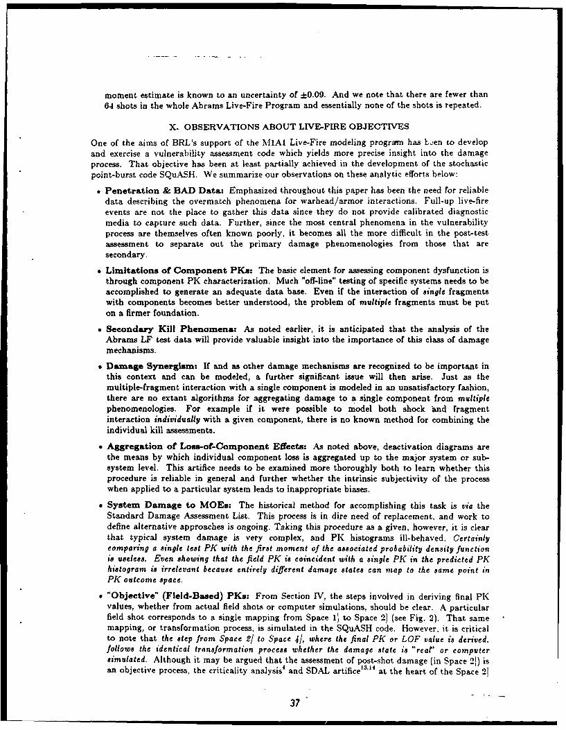
X. OBSERVATIONS ABOUT LIVE-FIRE OBJECTIVES............................ 37
DISTRIBUTION LIST.................................................... 43
Accession 'For
MTIS GRA&I
DTIC TABUnannounced fjustificatio
Distribut ion/_
Avalablit CoesAvail and/or
sist Special
r 'a 1aiit
o
LIST OF ILLUSTRATIONS
Figure Page
1. A listing of conventional Armored Fighting Vehicle (AFV) .......... 3damage mechanisms for the two principal AFV threats,Kinetic-Energy (KE) projectiles and Shaped-Charge (SC) jets.
2. Four Spaces of Vulnerability ......................................... 7
3. Four of the 25 MlA1 critical systems which support firepower ....... 16or mobility functions.
4. View of the MIAl from the front left ............................... 17
5. View of the MIAI from the rear right ............................... 18
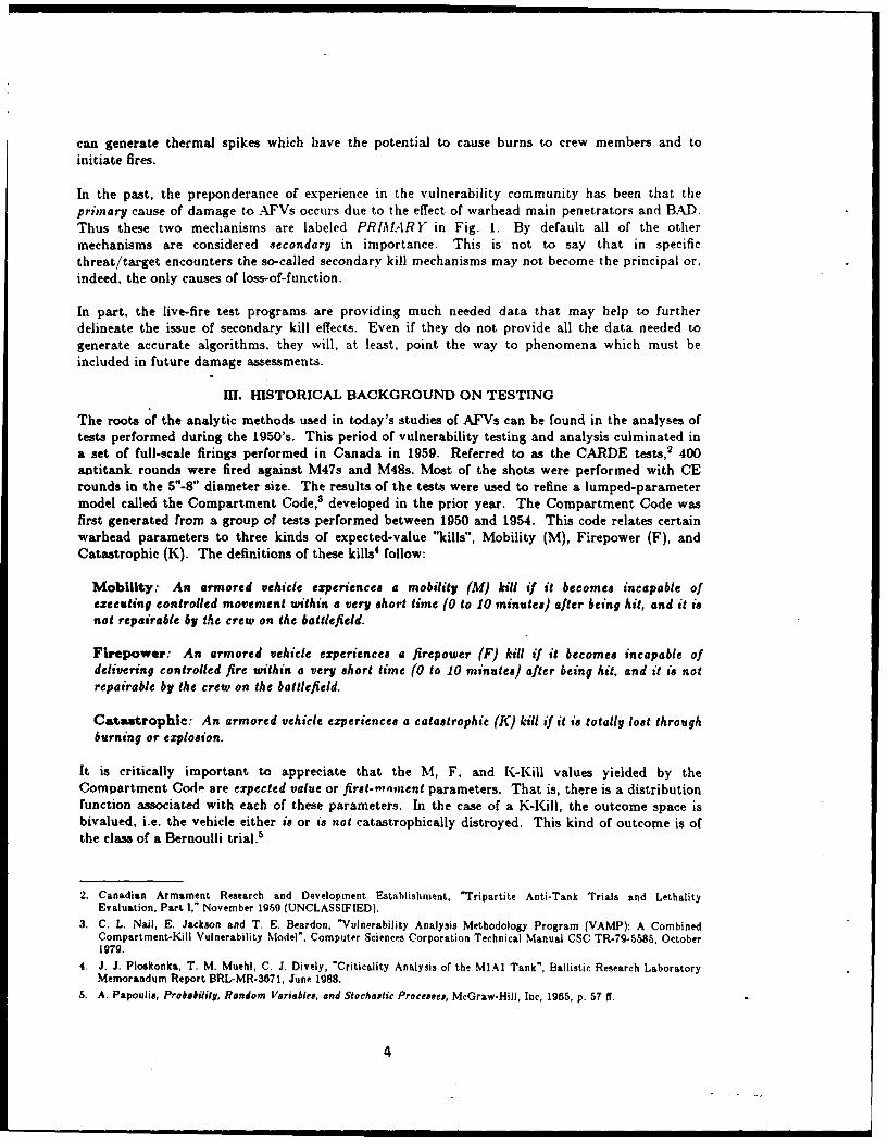
6. A sample deactivation diagram (or fault tree) for the .............. 20Fuel Supply subsystem shown in Fig. 3a.
7. Test configuration (above) and data (below) for a shaped-charge .... 21warhead (Ref. 25).
8. Exterior view of MIAI showing warhead attack location and .......... 23orientation.
9. Exterior view of MIAI as in Fig. 8 but from elevated ............... 23perspective.
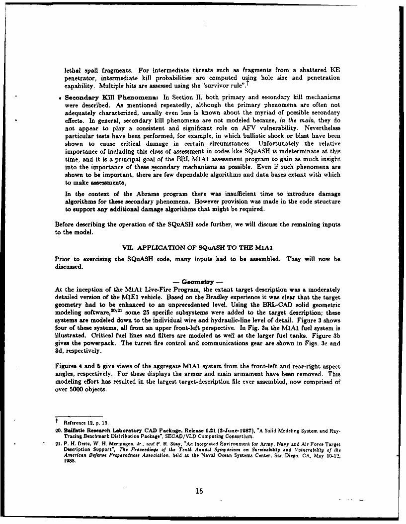
10. MIAI interior view in the turret-basket area ....................... 24
11. Histogram of Frequency of Occurrence vs. residual penetration ...... 26for the shot configuration illustrated in Figs. 8-10.
12. Image of crew compartment from the vantage point of the ............ 27warhead immediately exiting the interior armor.
13. Histograms of various kill categories derived from the ............. 34SQuASH simulation.
14. Test for convergence of means of average repeated tests ............ 36
iii
LIST OF TABLES
Table Paqe
I. Status of Penetration Data ........................................ 11
II. Status of Behind-Armor Debris (BAD) Data ......................... 12
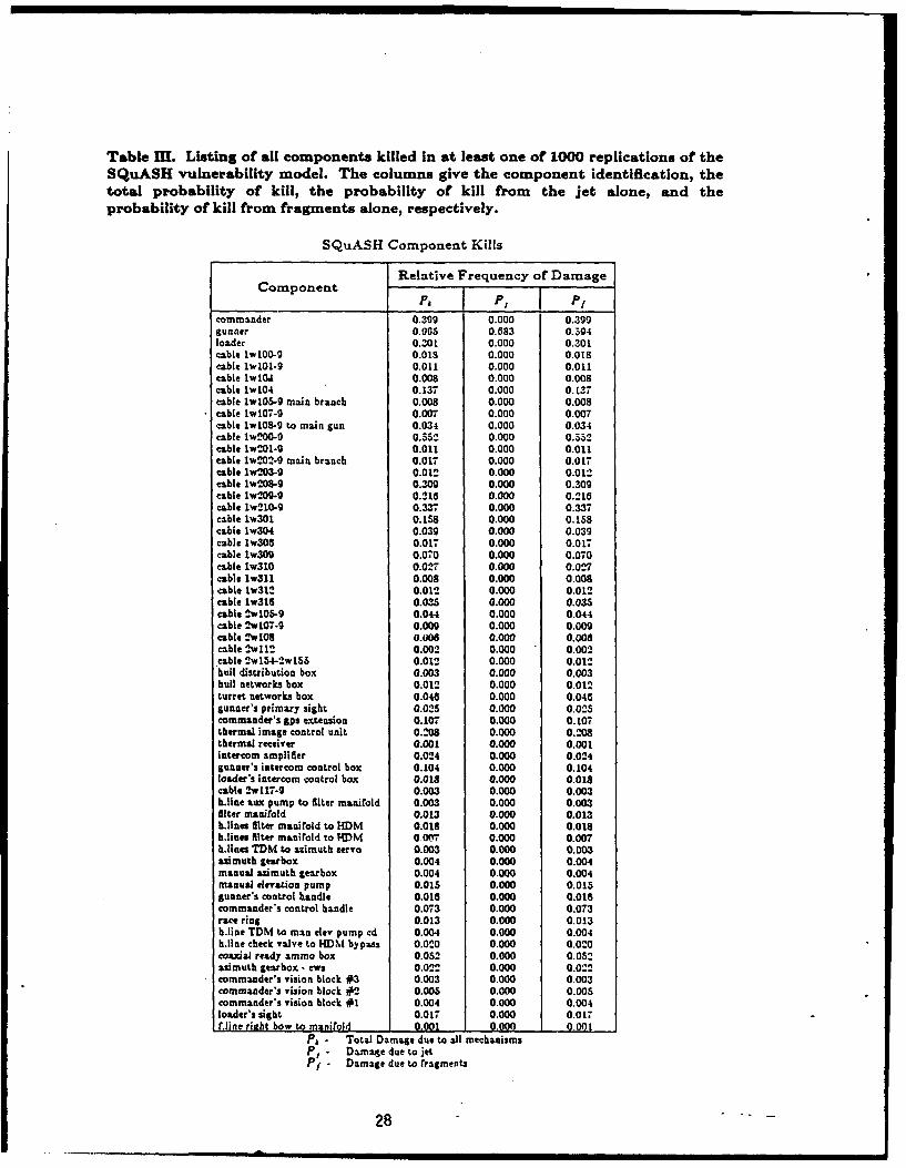
III. Listing of all components killed in at least one of 1000 ......... 28replications of the SQUASH vulnerability model.
IV. Damage states from the SQuASH simulation for the subset .......... 29CREW
V. Damage states from the SQuASH simulation for the subset .......... 29PROPULSION.
VI. Damage states from the SQuASH simulation for the subset .......... 30MAJOR ELECTRICAL.
VII. Damage states from the SQuASH simulation for the subset .......... 32ARMAMENT.
VIII. Damage states from the SQuASH simulation for the subset .......... 33OTHER.
v
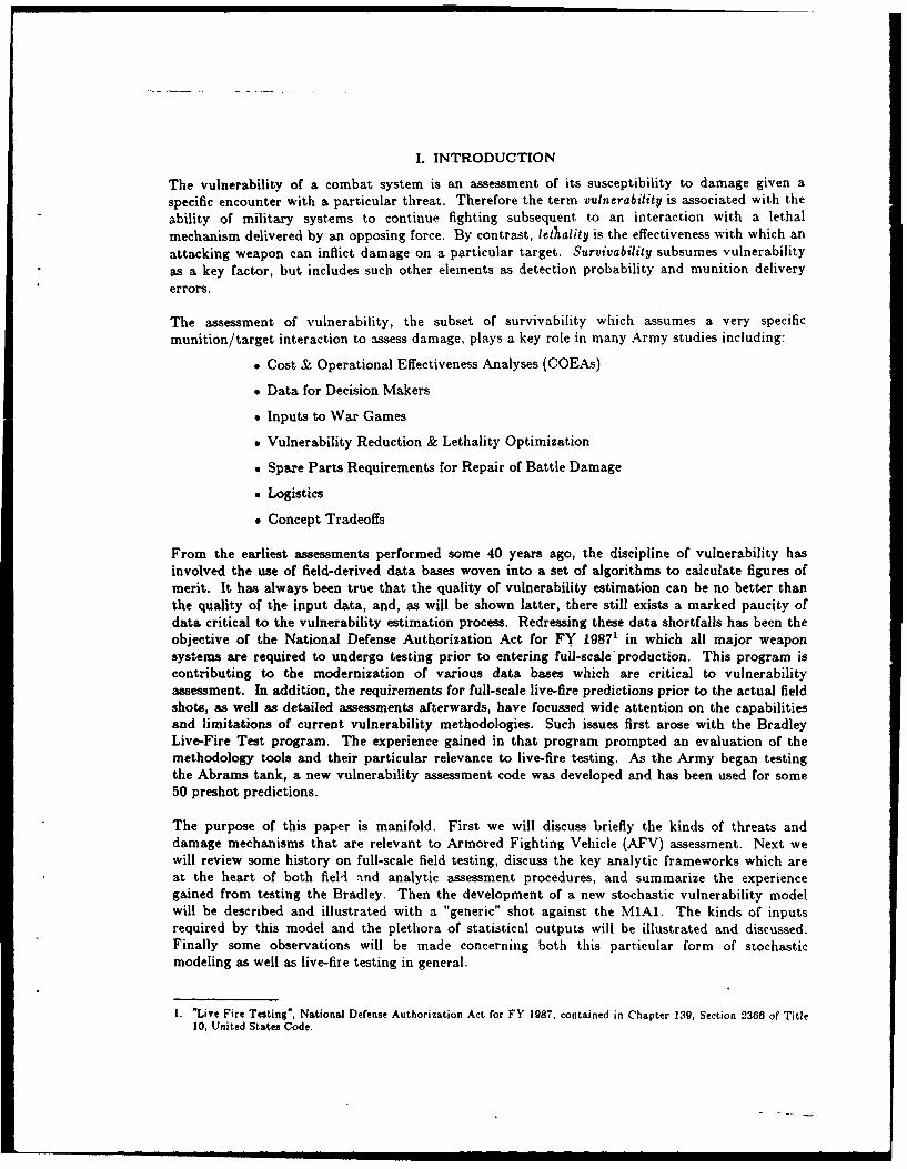
I. INTRODUCTION
The vulnerability of a combat system is an assessment of its susceptibility to damage given a
specific encounter with a particular threat. Therefore the term vulnerability is associated with the
ability of military systems to continue fighting subsequent to an interaction with a lethal
mechanism delivered by an opposing force. By contrast, lethality is the effectiveness with which an
attacking weapon can inflict damage on a particular target. Survivability subsumes vulnerability
as a key factor, but includes such other elements as detection probability and munition delivery
errors.
The assessment of vulnerability, the subset of survivability which assumes a very specific
munition/target interaction to assess damage, plays a key role in many Army studies including:
* Spare Parts Requirements for Repair of Battle Damage
* Logistics
* Concept Tradeoffs
From the earliest assessments performed some 40 years ago, the discipline of vulnerability hasinvolved the use of field-derived data bases woven into a set of algorithms to calculate figures ofmerit. It has always been true that the quality of vulnerability estimation can be no better thanthe quality of the input data, and, as will be shown latter, there still exists a marked paucity ofdata critical to the vulnerability estimation process. Redressing these data shortfalls has been theobjective of the National Defense Authorization Act for FY 19871 in which all major weaponsystems are required to undergo testing prior to entering full-scale'production. This program iscontributing to the modernization of various data bases which are critical to vulnerabilityassessment. In addition, the requirements for full-scale live-fire predictions prior to the actual fieldshots, as well as detailed assessments afterwards, have focussed wide attention on the capabilitiesand limitations of current vulnerability methodologies. Such issues first arose with the BradleyLive-Fire Test program. The experience gained in that program prompted an evaluation of themethodology tools and their particular relevance to live-fire testing. As the Army began testingthe Abrams tank, a new vulnerability assessment code was developed and has been used for some50 preshot predictions.
The purpose of this paper is manifold. First we will discuss briefly the kinds of threats anddamage mechanisms that are relevant to Armored Fighting Vehicle (AFV) assessment. Next wewill review some history on full-scale field testing, discuss the key analytic frameworks which areat the heart of both fiell and analytic assessment procedures, and summarize the experiencegained from testing the Bradley. Then the development of a new stochastic vulnerability modelwill be described and illustrated with a "generic" shot against the M1Al. The kinds of inputsrequired by this model and the plethora of statistical outputs will be illustrated and discussed.Finally some observations will be made concerning both this particular form of stochasticmodeling as well as live-fire testing in general.
1. "Live Fire Testing", National Defense Authorization Act for FY 1987. contained in Chapter 139, Section 2368 of Title10, United States Code.
I. CONVENTIONAL AFV DAMAGE MECHANISMS
In terms of conventional munitions that confront AFVs, we give the following list:
" Kinetic-Fnergy (KE) Rounds
" Chemical Energy (CE) Munitionso Shaped-Charge (SC) Roundso Explosively Formed Projectiles (EFPs)" Artillery Fragmentso Mines
Of the five munitions of threat to AFVs, the KE and SC rounds are the most important. Toderive some insight into possible damage mechanisms, we refer to Fig. 1. Here we have listedvarious phenomenologies which can lead to AFV damage, broken out by KE vice SC threats andby damage location, exterior vice interior.
-KE Threats/Exterior-Taking first the KE class of threats, damage to exterior components can occur directly frompenetration as well as indirectly from shock waves propagated from the point of impact. Inaddition, it sometimes occurs that when a KE penetrator strikes the glacis of a tank, erodedmaterial is splashed up and beyond the point of impact. This spray of material can degrade ordestroy relatively sensitive components such as vision blocks and also jam turret rings.
-KE Threats/Interior-If a portion of a KE main penetrator breaches the armor package, the residual can causesignificant damage to interior components. Behind-armor debris (BAD), irregularly shapedmaterial exiting from the back surface of the armor, can also cause significant damage to interiorcomponents. BAD can be divided into three categories: (a) direct, debris which flies directly to acomponent causing damage, (b) secondary, debris which is generated at an internal barrier, and (c)indirect, deflected debris (ricochet).
Other phenomenologies contributing to interior damage are shock propagated from the exteriorKE striking point into internal components, the initiation of fire, hydraulic ram, and pyrophoriceffects. Hydraulic ram effects can be observed when fluid volumes are impacted; the intensepressure spikes that result can disable critical components contiguous to the fluid.
-CE Threats/Exterior--In contrast to a KE round, when a CE round strikes, a blast wave is created by the action of thewarhead initiation. Although by design the kill mechanism is penetration by a jet, the blast wavecreated by the detonation, even on heavy vehicles, can damage suspension and other externalcomponents which are relatively delicate (e.g. sighting devices). In the case of lightly armoredvehicles, the warhead delivery system can cause significant damage due to the ballistic impacts ofrocket-motor housings, etc. As with KE rounds, hydraulic-ram damage can occur with CEwarheads, and the blast effects can breech light armors.
-CE Threats/Interior-As in the case of NE penetration, CE rounds can generate residual main penetrator elements (herejet residual) and BAD. Shock damage can occur due to blast waves from warhead detonation. Asin the KE case, fire and hydraulic ram effects can be generated. CE rounds have some otherphenomenologies which sometimes accompany impact: when a jet enters or exits an enclosedvolume, a blast wave is generated which reflects within the enclosure. Such wdves have thepotential of causing damage chiefly to personnel (ears, lungs). Some tests have indicated thatwhen CE jets penetrate aluminum armor, toxic gases may be produced. At the same time intenseflashes of light can be produced (luminosity); this phenomenon has the potential to causetemporary (flash) blindness in crew members. Finally, CE jet, entry into interior compartments
Figure 1. A listing of conventional Armored Fighting Vehicle (AFV) damagemechanisms for the two principal AFV threats, Kinetic-Energy (KE) projectilesand Shaped-Charge (SC) jets. The phenomenologies are further divided into 1]EXTERIOR and 2] INTERIOR effects. Some phenomenologies are common to boththreat; others are unique. Based on the preponderance of AFV test experience,the majority of damage comes from warhead residual penetrator entry into interiorAFV volume together with Behind-Armor Debris. For both kinds of threats theseare labeled PRIMARY All other phenomena are in general considered Secondary, butin specific warhead/target encounters may contribute to significant damage.
I I i • • 3
can generate thermal spikes which have the potential to cause burns to crew members and toinitiate fires.
In the past, the preponderance of experience in the vulnerability community has been that theprimary cause of damage to AFVs occurs due to the effect of warhead main penetrators and BAD.Thus these two mechanisms are labeled PRIAJARY in Fig. 1. By default all of the othermechanisms are considered secondary in importance. This is not to say that in specificthreat/target encounters the so-called secondary kill mechanisms may not become the principal or,indeed, the only causes of loss-of-function.
In part, the live-fire test programs are providing much needed data that may help to furtherdelineate the issue of secondary kill effects. Even if they do not provide all the data needed togenerate accurate algorithms, they will, at least, point the way to phenomena which must beincluded in future damage assessments.
I. HISTORICAL BACKGROUND ON TESTING
The roots of the analytic methods used in today's studies of AFVs can be found in the analyses oftests performed during the 1950's. This period of vulnerability testing and analysis culminated ina set of full-scale firings performed in Canada in 1059. Referred to as the CARDE tests, 2 400antitank rounds were fired against M47s and M48s. Most of the shots were performed with CErounds in the 5"-8" diameter size. The results of the tests were used to refine a lumped-parametermodel called the Compartment Code,3 developed in the prior year. The Compartment Code wasfirst generated from a group of tests performed between 1950 and 1954. This code relates certainwarhead parameters to three kinds of expected-value "kills", Mobility (M), Firepower (F), andCatastrophic (K). The definitions of these kills4 follow:
Mobility: An armored vehicle experiences a mobility (M) kill if it becomes incapable ofexecuting controlled movement within a very short time (0 to 10 minutes) after being hit, and it isnot repairable by the crew on the battlefield.
Firepower: An armored vehicle experiences a firepower (F) kill if it becomes incapable ofdelivering controlled fire within a very short time (0 to 10 minutes) after being hit, and it is notrepairable by the crew on the battlefield.
Catastrophic: An armored vehicle experiences a catastrophic (K) kill if it is totally lost throughburning or explosion.
It is critically important to appreciate that the M, F, and K-Kill values yielded by theCompartment Cod are expected value or first-minent parameters. That is, there is a distributionfunction associated with each of these parameters. In the case of a K-Kill, the outcome space isbivalued, i.e. the vehicle either is or is not catastrophically distroyed. This kind of outcome is ofthe class of a Bernoulli trial.6
2. Canadian Armament Research and Development Establishment, "Tripartite Anti-Tank Trials and LethalityEvaluation, Part I," November 1959 (UNCLASSIFIED).
3. C. L. Nail, E. Jackson and T. E. Beardon, "Vulnerability Analysis Methodology Program (VAMP): A CombinedCompartment-Kill Vulnerability Model". Computer Sciences Corporation Technical Manual CSC TR-79-.5585, October1979.
4. J. J. Ploskonka. T. M. Muehl, C. J. Dively, "Criticality Analysis of the MIA1 Tank", Ballistic Research LaboratoryMemorandum Report BRL-MR-3671, June 1988.
5. A. Papoulis, Probability, Random Variables, and Stochastic Processes, McGraw-Hill, Inc, 1965, p. 57 ff.
4
Until the onset of the current live-fire programs, the pre-CARDE and CARDE trials representedthe largest collection of full-scale firings ,gainst full-up heavy armored vehicles. By 1960 some1400 firings had taken place with large munitions against heavy AFVs. There were, however,some other full-scale firings performed as the BRL continued to update its vulnerability data base.
Between 1963 and 1976 various full-scale tests were performed including small CEs vs. ArmoredPersonnel Carriers (110 shots; 1964), High-Explosive Projectiles vs. tanks (228 shots; 1971),Influence-Fused Mines vs. tanks (172 shots; 1973), GAU-8 Munitions vs. tanks (153 hits; 1975), andDepleted-Uranium KE Penetrators vs. tanks (6 shots; 1976).
In 1977, the BRL performed an inhouse study to examine what methods, experiments, and databases were required to modernize its AFV analytic methods. Already the XC%1 main battle tankwas in advanced development using various modern armors never fired against in a combat-readyconfiguration. Although the BRL was not able to obtain Mis for full-scale firing, a set ofcontrolled full-up firings was performed in Soccoro using M-48s. 7 KE warheads were fired and theresults used to extend once more the BRL vulnerability data base.
From the time of the Soccoro tests until 1983, the utilization of modern armors (special, spaced,ceramic, etc.) increased in US vehicles. By this time the utility of the CARDE data (obsoleteprojectiles against monolithic targets) was clearly of diminishing value. In an attempt tomodernize its vulnerability data base and methods, the BRL proposed a program calledARBADAM5 in 1983. Although never funded, this proposal highlighted the critical need forcomprehensive testing and set the stage for the current full-scale test programs Joint Live Fire(JLF) and Live Fire Testing (LFT).
The first to get underway was SLF. Chartered in 1984 as a DoD-sponsored and funded program,it employs joint technical coordinating groups for multi-service effectiveness. The overall thrust ofJLF is to evaluate combat systems that have already been fielded. To date the types of systemsthat have been or are being tested include armored personnel carriers, tanks, fixed and rotary wingaircraft, and a wide variety of guided and unguided munitions.
Following the inception of JLF, the Defense Authorization Act of FY 19871 mandated LFT toevaluate the performance of all important combat systems prior to their entering full-scaleproduction. An important series of tests took place against the M2/M3 or Bradley class offighting vehicles.'.The BRL was tasked with predicting shot outcomes before the firings, as well ashelping to assess the results of field tests. The results of the shots were also used to upgrade themodel used in the Bradley program. That code, called VAST,1" with origins in the early 1970s,was one of the first of a number of ground vulnerability assessment codes of the point-burst class.In contrast to the Compartment Code, which treats interior vehicle damage using lumped-parameter functions, point-burst codes attempt to evaluate explicitly the complex behind-armordebris environment created by overmatching munitions, its interaction with critical interior
S. D. F. Menne, G. L. Durree, R. L. Kirby, J. P. Lambert, M. L. Lampson, J. J. Ploskonka, J. R. Rapp and E. P. Weaver,"Plans for Updating the Armored Vehicle Lethality/Vulnerability Methodology and Data Base", Special Report for theDirector, Ballistic Research Laboratory, 22 August, 1977.
7. D. A. Ringers and F. T. Brown, "SLAVE (Simple Lethality and Vulnerability Estimator) Analyst's Guide", BallisticResearch Laboratory Technical Report ARBRL-TR-02333, June 1981, AD B059679.
8. G. A. Bowers, P. J. Tanenbaum and S. F. Polyak, "Program Recommendation for Assessment and Repair of BattleDamage to Combat Materiel (ARBADAM)", 7 June 1984.
9. "Bradley Survivability Enhancement Program, Phase II, Live Fire Test Report", prepared by the USA Test andEvaluation Command, the USA Ballistic Research Laboratory, the USA Materiel Syttems Analysis Activity, the USACombat Systems Test Agency, and the Office of the Surgeon General, 29 June 1987 (Report Classified SECRET).
10. C. L. Nail, *Vulnerability Analysis for Surface Targets (VAST)- An Internal Point-Burst Vulnerability AssessmentModel - Revision I", Computer Sciences Corporation Technical Manual CSC TR-82-.5740, August 1982.
5
components, and the resulting decrease in vehicle functioning. This class of code will be explainedin w .e detail in the next section.
Following the Bradley program, the Abrams Main Battle Tank was scheduled for testing. Basedon the Bradley experience, it became clear that a new analytical framework was required topredict and analyze properly the full-scale testing of the Live-Fire Program. In Section V, the keyevidence for that conclusion will be presented.
IV. CONCEPTUAL FRAMEWORK FOR AFV VULNERABILITY ASSESSMENT
To understand the nature of vulnerability/lethality assessment of AFVs, it is critical tounderstand the framework within which all assessments for the past 40 years have taken place.This framework is not just implicit to computer-based assessments, but provides a key link toprocessing live-fire test results as well.
The vulnerability process can be thought of as a transformation or mapping of information amongfour number domains or spaces. Points in a lower number space are mapped to higher spaces byexperimental processes and/or mathematical (modeling) transformations. As illustrated in Fig. 2,Space 11 defines the myriad of details concerning the interaction of a specific munition against aspecific AFV target. With respect to a munition, this includes the mass, velocity, shape,orientation, etc. In terms of the target, the specifics include all of the three-dimensional geometry(including armor packages and interior components), material properties, interdependency ofsystem functioning, etc., and the munition impact location.
Whether a real bullet is fired against a target in the course of a live-fire experiment or acomputer-based simulation is performed to that end, damage to the target can accrue as a resultof the interaction. In the case of an undermatching munition, it may be that no damage occurs.In any case, the state of the target after the interaction is defined in terms of the vehicle criticalcomponents; a critical component is any component, the loss of which would result in thereduction in a mobility or firepower capability of the vehicle. Past and current practice invulnerability assessment is to describe individual components in crisp binary states, i.e. killed ornot killed. At the component level no partial functioning is allowed. Following a shot on an AFVthe damage state of the vehicle is defined as the full accounting of all vehicle critical components.Each point within Space 11 represents one of a large ,uncountable) number of possiblebullet/target interactions. As noted above each specific bullet/target state is characterized byliterally hundreds of thousands of numbers representing the state of the system geometry, materialconstituencies, component interconnectivities, warhead penetration performance parameters, etc.The many points in Space 2) imply a large, but nevertheless countable, number of possibleoutcomes that may occur following a bullet/target interaction. If an AFV is constructed of ncritical components, then the (countable) space of points in Space 2] is 2a. In the case of the MIA1,the corresponding BRL-generated target description is composed of approximately 750 criticalcomponents. Since no individual shot has a significant likelihood of killing all components in thetarget, the size of Space 21 is far fewer than 2' points. However in just the turret-basket area ofthe MIAl, there are some 400 components; if only one-fourth of those components were likelycandidates for damage, there remain on the order of 2 ° ° possible damage states, representingabout I0 ° possible outcomes!
Thus a LF test is an experiment which provides a single transformation from a point in Space 11to a point in Space 21. Later we will see that if a LF experiment were repeated, the single point inSpace 11 could map to many different points (corresponding to many different damage states) inSpace 21. \We will also examine a vulnerability code which can be used to emulate that process.
Given a particular damage state in Space 21, by definition a set of critical components no longerworks. Thus there may be some reduction in the firepower or mobility. function of the AFV. Space31 represents an objective measure of this diminution in performance. In the case of firepower
6
Spacel] **
Space 2] *~*~
{Space 3]} DALSpace.4 . I -- DAL
1] Warhead/Target Interaction
2] Component Damage State(s)
3] Measures of Performance (MOPs)[Loss of Automotive/
Firepower Capabilities]
4] Measures of Effectiveness (MOEs)[Reduction in Battlefield Utility,
"PKs", or "Losses-of-Function"]
Figure 2. Four Spaces of Vulnerability. Space 1] represents all combinations ofspecific warhead/target encounters. Space 2] represents all possible damage statesof an AFV. Objective Measures-of-Performance (MOPs) are represented by Space3], while Space 4] characterizes Measures-of-Effectiveness (MOEs). A Live-Fire shotcan be thought of as a mapping from a point in Space 1] to Space 2]. Space 3] isnot evaluated in AFV analyses, so the mapping processes and domain are shown indashed lines. For 30 years standard practice has been to map AFV componentdamage (states) in Space 2] to Space 4] using the (Standard) Damage AssessmentList (DAL).
7
function, characterization of Space 31 might be in terms of a reduction in rate of fire, an increasein time to acquire a target, or the growth in hit dispersion of the main gun. In the case ofmobility, Space 3] might be represented by reduction of top speed, reduction in acceleration, orreduction in rough-terrain crossing ability. Space 3] can be thought of as represented by objectiveMeasures of Performance (MOPs). Although Space 3] is in principle of great interest to manyconcerned with vulnerability analysis, there is no implemented mechanism for this mapping.Hence both the mapping process and the domain are represented with dashed lines in Fig. 2.
Finally Space 4) is a domain which historically was defined as a probability space. It is actuallycomposed of a number of sub-spaces, one describing a K-Kill criterion. Two other sub-spacesdescribe mobility and firepower. The M and F metrics are constrained to the interval
0.0 < PFK < 1.0and
o~o< P< < 1.0where
0 -MK
and P FK _ Probability of Firepower Kill
P,< M Probability of Mobility Kill.
The significance of Space 4] is in terms of a Measure of Effectiveness (MOE) where an MOE" isdriven in terms of the definitions of the Mobility and Firepower Kills given in Section III.
Following the pre-CARDE trials, a mapping artifice was developed (circa 1957) called theStandard Damage Assessment List (SDAL). The SDAL is a listing of some 120 major systems andcomponents which comprise an AFV. Later modified by a board of Army officers and armorspecialists (circa 1959), it represents their best estimates of the relative Combat Utility (CU) of avehicle given the loss of each specified system or component. These estimates assume all possiblecombat scenarios, both offense and defense, and tank doctrine as then promulgated. The acceptedpractice has been to equate the Decrement in Combat Utility (DCU)f with a probability of kill.However it has been recognized for some time that this process has serious flaws both from amathematical and an implementation standpoint. 2 For example it is clear that the decrement incombat utility is not equatable to a probability function. And there are problems with themassive amounts of mental averaging that are performed by the committees involved in thisprocess. Also, due to the process of averaging over so many scenarios, the effect of the loss of aparticular system may be washed out for subsequent use in a war game in which a context-specificscenario is being played.
As this problem was identified in the last ten years, some workers dropped the label "Probabilityof Kill" in favor of "Expected Loss-of-Function" for the respective M and F variables. However,this is a disingenuous stratagem in view of the fact that consumers of vulnerability estimatescontinue to use them as probabilities. Probably the best that can be said about the SDAL processis that it has been used as an essentially consistent metric for 30 years. On the other hand, itmust be noted that the outputs of the SDAL process, whether called "PKs", "LOF8", or "DCU8",have no assignable meaning except for the extremes of 0.0 and 1.0! This in spite of the way inwhich war gamers or any other users of AFV vulnerability data arbitrarily choose to use thenumbers.
11. P. H. Deitz, "The Future o Army Item-Level Modeling", in the Proceedings of the .XIV Annual meeting of the ArmyOperations Research Symposium, 8-10 October 1985. Ft. Lee, VA.The Decrement in Combat Utility is the complement of Combat Utility.
12. J. R. Rapp, "An Investigation of Alternative Methods for Estimating Armored Vehicle Vulnerability", BallisticResearch Laboratory Memorandum Report ARBRL-MR-032W0, July 1983.
8
Nevertheless, because modern tanks have many critical systems/components which were not a partof the original SDAL, other vulnerability workers have generated an updated DAL. This task wascompleted under the auspices of the AF-sponsored Chicken Little Program. 13' 14 Offense anddefense scenarios were examined separately as well as averaged. For the first time the frameworkfor this process was also documented. 13"14 However, the BRL has deferred adoption of the newSDAL values in favor of attempting to define new sets of kill definitions that are bothmathematically consistent and directly relatable to field damage states (Space 2)).' s The ArmyMateriel Systems Analysis Activity (ANISAA) is assisting the BRL in those objectives.
Thus since the mid-1950s, the standard practice in AFV vulnerability has been to utilize the SDALto map damage states from Space 2] directly to Space 4]. That standard procedure has beenutilized in the Abrams program for the derivation of the Mobility and Firepower LOF estimatesreported later. As noted above, no mechanism exists for evaluating Space 3]. It can be seen thatthe DAL mapping from Space 2] to Space 4] is intrinsic to all vulnerability analyses whether basedon field shots or computer simulations.
- Compartment Model -
The Compartment Model was based originally on the individual damage states observed fromsome 1400 firings. For each shot, the observed damage state was mapped to the related PK andP . Lumped parameter curves, called damage correlation curves were fitted to these data. Theresult was a first-moment vulnerability estimate for the specific munition/target combinationstested. The Compartment Model can be thought of as a model which maps bullet/targetcombinations directly from Space 1] to Space 4].
- Compartment-Model Logic -
The logic of the Compartment Model follows:
1] Intersect ray with target geometry to simulate threat trajectory
2] Check for Exterior Damage (Suspension, Gun Tube)
31 Check for Perforation
41 If Perforation, check for K-Kill due to main penetrator impacting on Fuel/Ammunition
5] If Perforation, then utilize damage correlation curves to estimate magnitude of M and FKills for each compartment breached. These include K-Kill from fragments impactingammunition.
61 Assume independence and use probabilistic "survivor rule "t to sum up all kill contributions.
The model is only as good as the data base and historically has been based on firings ofincreasingly antiquated munition/target pairings. In a future effort, the results of a calibratedpoint-burst model will be used to upgrade variants of the Compartment Model for variouscombinations of munition/targets.
13. G.A. Zeller, "Update of the Standard Damage Assessment List (SDAL) for Tanks", Executive Summary, ASI SystemsInternational Report 87-14, October 1987.
14. G. A. Zeller and B. F. Armendt, "Update of the Standard Damage Assessment List for Tanks: Underlying Philosophyand Final Results", Submunition Evaluation Program, Project Chicken Little, Report AD-TR-65, November 1987.
15. M. W. Starks, "New Foundations for Tank Vulnerability Analysis", The Proceedings of the Tenth Annual Symposiumon Survivability and Vulnerability of the American Defense Preparedness Association, held at the Naval Ocean SystemsCenter, San Diego, CA, May 10-12, 1988.
t Reference 12, p. 16.
9
It is important to note that there is a long-term requirement for the maintenance of this class ofmodel. Many important vulnerability/lethality studies are required for targets and/or munitionsfor which detailed information is not available. This situation is encountered, for example, in thestudy of foreign AFVs for which knowledge is limited or in US concept tradeoffs where only afirst-cut design exists.
- Point-Burst Modeling -
During the early 1970s, the first point-burst model was developed. Called VAST, 10 this modelattempts to model the behind-armor residual penetration and behind-armor debris environment.Greatly more complex than the Compartment Code, point-burst models require a knowledge ofdetailed debris data for every warhead/armor pairing that will be encountered in an analysis. Fora given shot, VAST gives the probability of killing any critical component (singly) within thevehicle. Although this is a Space 21 parameter, VAST has no capability of calculating theprobability of encountering killed components in combination. Thus there is no capability ofmatching the observed damage state of a field experiment with a model prediction of Space 21.VAST uses the SDAL mapping process to calculate a first-moment estimate of the PFK and PMY aswell as the K-Kill (Bernoulli) values.
It is worth noting that in vulnerability assessment there is no truly predictive model. All classes ofmodels are built on experimental data. In the case of the Compartment Code, the data involvesfull-scale firings. After curve-fitting, the "predictions" of the kill probabilities can only be inferredfor the particular munition/target combinations tested. The model cannot accommodate changesin the target configuration to examine vulnerability reduction or other modifications. And giventhe limited statistical sample for any set of full-scale firings, the results may result in considerablearbitrary bias. In the case of point-burst modeling, the vulnerability estimates are actuallyperformed by aggregating the results of various "off-line" experiments involving many tests withwarhead/armor pairings as well as component testing to calibrate the susceptibility of componentsto fragment damage. Although system geometry can be modified, there are voluminous amountsof input data that must be assembled. Often there is insufficient data on particularwarhead/armor pairings and concomitant behind-armor debris (BAD) data.
Recently the BRL documented the state of warhead/armor and BAD characterization.16 Thesedata are replicated in Tables I and II. It can be seen from these tables that many of the newer-threat/modern-armor pairings present combinations for which little or no reliable data areavailable.
In the next section, we will discuss how the VAST model was applied to the Bradley Live-FireProgram.
V. EARLY LIVE-FIRE EXPERIENCE
When the requirements for vulnerability modeling in conjunction with the Bradley Live-FireTesting first arose, BRL analysts considered various code options. The Compartment Model wasconsidered and rejected for a number of significant limitations:
No full-up firings had ever been. performed against the Bradley. Thus there were noempirically based Compartment Model damage correlation curves traceable to the testconfiguration.
1o. D. L. Rigotti, 'Vuinerability/Lethality Assessment Capabilities - Status, Needs, Remedies", The Proceedings of theTenth Annual Symposium on Survivability and Vulnerability of the American Defense Preparedness Association, held atthe Naval Ocean Systems Center, San Diego, CA, May 10-12, 1988.
10
1
0
01
a
V3 to V3
z0
aa
IF s
W0
aA
140
aA
a Ia~8.
I.oH - H - - - - -
*a
* 0
0
U axU
o .~..) - - - .. 4 - - - -~ qj* ~ aa a
43* 4 ~.
.;.~ SU U -*
A43
- . I-.8'S
~U .- d UN 4.o ~ 'ii
A* -~ U .~ a I
K ~ - - - -I. S43 - a* -.-- .~ ~ 0
0 ~5*0 .8*0
A 0
* 0.5
d43 S5* a
H H - -i -4 - .4 H ~ I
~1.~ 1*0.8.8 *
a
k a u ~ w ~-
A a* :a -~
k H 10 H .4 H - 4 Ho0
A
U.- a - U.-U .8
SI..rs2 a ~.aU .8.* a a -* 8.
~ ~43Uj~
.243
0
12
" Even had damage correlation curves been available for a prior configuration of the Bradley, noparametric excursions from the system baseline would have been possible. This would haveprecluded examining the effects, for example, of reconfiguring the location and shielding ofinterior components.
" The Compartment Code does not predict component damage. thus it could produce no metricdirectly comparable with a field observable.
Essentially the only available option was to utilize the VAST computer code. This code was usedto make some 76 pre-shot predictions.9
The results of the exercise are summarized from an analytic perspective here:
a The predictions of VAST were compared with corresponding Live-Fire Field results on a shot-by-shot basis. This was not an ideal choice however, because, as noted above, VAST, like allother vulnerability codes up to this time, is a first-moment predictor; that is, only the expectedkill values are produced. At the time, nothing was known about the probability densityfunctions associated with mobility and firepower kills. Lack of appreciation for the possiblevariability of test results led to a widespread practice of comparing expected-value output ofthe code to single outcomes from the Live-Fire tests. Based on the most elementaryconsiderations of basic statistics, this is an analytic non-sequitur!
* Nevertheless, model "validation" was carried out by such comparisons. The GeneralA- <unting Office 17 performed a detailed summary of VAST and the Bradley test results. Thepredictions and fielI results were compared side-by-side. One critic from the Office ofSecretary of Defense' rated the "validity" of the Bradley predictions on whether they fellwithin 30% of the expected-value estimates. This in spite of the fact that nothing was knownabout the probability density functions associated with the PKs.
" As noted above, neither VAST nor any of the other extant point-burst models gave any insightinto the probability of encountering specific damage states, and specific damaged componentsrepresent the principal yield of the testing process.
" The Bradley tests showed that damaging a single small component can dramatically affectsystem loss-of-function. In one case the cutting of a single wire by an off-axis fragmentresulted in a significant loss-of-firepower function.
Thus as the BRL embarked on the Abrams Live-Fire program it became clear that there was asignificant need for a stochastic point-burst model with the following general characteristics:
* The target description modeling would have to be accomplished at an unprecedented level ofdetail.
* The vulnerability model should be capable of reflecting the chief forms of variability in thevulnerability process that could lead to shot-to-shot variations in damage. This should includeboth variations in the causes of component damage, given a hit, and random (spatial)deflections of lethal fragments.
" The vulnerability model should calculate damage states on a repeated (Monte Carlo) basis sothat probabilities of individual state outcomes could be assessed.
17. "Live Fire Testing: Report to the Chairman, Subcommittee on Seapower and Strategic and Critical Materials,Committee on Armed Services, House of Representatives' , United States General Accounting Office ReportGAO/PEMD-87-17, August 1987.Reference 17, p. 124.
13
* The vulnerability model should map the damage states to probability density functions in PKspace (Space 4]) so that the variabilities in outcome space could be assessed.
The development of the new model is described in the next section.
VI. SQuASH
To meet the requirements of the Abrams Live-Fire program, a totally new class of stochasticpoint-burst model was developed." Called SQuASH (for Stochastic Quantitative Analysis ofSystem Hierarchies), this code was designed to accommodate the threats enumerated in Section II,including the special case of multiple hits (salvo-fired weapons).
Accommodation was made to vary stochastically the following variables:
" Hit Point: Under the best conditions, the geometric modeling of a complex target cannotperfectly reflect real vehicles. In addition, actual vehicles vary from copy-to-copy in so far aswire routing, etc. The geometric interrogation process involves shooting (zero-width) raysthrough the target to replicate possible projectile paths. The process only yields componentswhich would be intercepted by the axis of a projectile, not those that would be impacted by theoff-axis body. Thus rather than a single ray normally used to model a striking projectile, amatrix of nine rays was chosen to provide sampling over a six-inch cross section.
" Warhead Performance: Normally warhead performance is modeled in terms of its expected(point-value) penetration capability. Repeated warhead/armor experiments using precisioncomponents reveal random variations in depth of penetration, etc. The SQUASH codeassociates a distribution function with all warhead/armor calculations; in the course of modelexercise, random draws are made from this distribution function.
" Residual Penetrator Deflection: In the case of KE projectiles incident at oblique angles,the residual portion of a penetrator can deflect upon exiting armor. The deflection is greatestnear the limit velocity when the armor is just being overmatched. A distribution function isutilized here to select trajectories in the vicinity of the expected deflection.
* Spall Production: The VAST code uses a spall model based on BAD described in terms offragment mass, velocity, and shape factor13 Since much of this information is lacking (as notedin Table H) for many warhead/armor pairings in the MIA1 program, a spall model based on anotion of lethal fragments was used. For the past ten years, the US has standardized spallcollection by means of a package of thin metallic plates." Lethal fragments for these purposesare defined as those fragments which penetrate at least the first plate in this combination pack.
The SQUASH spall model is based on a routine which describes the spatial density of lethalfragments as a bivariate gaussian distribution. The solid angle subtended by any criticalcomponent and its location then defines the expected number of lethal fragment impacts. Inthe exercise of the code for a particular shot, the expected number of fragments is used in aPoisson distribution to draw a specific number of fragments. This particular number offragments is then evaluated against the given component.
" Component PK/H Characterization: Each critical component in the target is separatelycharacterized in terms of its probability of being killed by main penetrators and by single
18. A. Ozolins, *Stochastic High-Resolution Vulnerability Simulation for Live-Fire Programs," The Proceedings of theTenth Annual Symposium on Surtivability and Vulnerability of the American Defense Preparedness Association. held atthe Naval Ocean Systems Center, San Diego, CA, May 10-12, 1988.
19. S. Corbett, J. Suckling, M. Chick, and C. Helleur, "Development of Improved Techniques for the Evaluation or BehindArmour Effects", Report or the Key Technical Areas 9 & 12. The Technical Coordination Program (TTCP), Panel W-1, July 1987.
14
lethal spall fragments. For intermediate threats such as fragments from a shattered KEpenetrator, intermediate kill probabilities are computed using hole size and penetrationcapability. Multiple hits are assessed using the "survivor rule".'
e Secondary Kill Phenomena: In Section II, both primary and secondary kill mechanismswere described. As mentioned repeatedly, although the primary phenomena are often notadequately characterized, usually even less is known about the myriad of possible secondaryeffects. In general, secondary kill phenomena are not modeled because, in the main, they donot appear to play a consistent and significant role on AFV vulnerability. Neverthelessparticular tests have been performed, for example, in which ballistic shock or blast have beenshown to cause critical damage in certain circumstances. Unfortunately the relativeimportance of including this class of assessment in codes like SQUASH is indeterminate at thistime, and it is a principal goal of the BRL MIAI assessment program to gain as much insightinto the importance of these secondary mechanisms as possible. Even if such phenomena areshown to be important, there are few dependable algorithms and data bases extant with whichto make assessments.
In the context of the Abrams program there was insufficient time to introduce damagealgorithms for these secondary phenomena. However provision was made in the code structureto support any additional damage algorithms that might be required.
Before describing the operation of the SQUASH code further, we will discuss the remaining inputsto the model.
VII. APPLICATION OF SQUASH TO THE MIA1
Prior to exercising the SQUASH code, many inputs had to be assembled. They will now bediscussed.
- Geometry -
At the inception of the MIA1 Live-Fire Program, the extant target description was a moderatelydetailed version of the MIEI vehicle. Based on the Bradley experience it was clear that the targetgeometry had to be enhanced to an unprecedented level. Using the BRL-CAD solid geometricmodeling software, 2'
21 some 25 specific subsystems were added to the target description; thesesystems are modeled down to the individual wire and hydraulic-line level of detail. Figure 3 showsfour of these systems, all from an upper front-left perspective. In Fig. 3a the MIAI fuel system isillustrated. Critical fuel lines and filters are modeled as well as the larger fuel tanks. Figure 3bgives the powerpack. The turret fire control and communications gear are shown in Figs. 3c and3d, respectively.
Figures 4 and 5 give views of the aggregate MiAl system from the front-left and rear-right aspectangles, respectively. For these displays the armor and main armament have been removed. Thismodeling effort has resulted in the largest target-description file ever assembled, now comprised ofover 5000 objects.
t Reference 12, p. 16.
20. Ballstle Research Laboratory CAD Package. Release 1.21 (2-June-1987), "A Solid Modeling System and Ray-Tracing Benchmark Distribution Package", SECAD/VLD Computing Consortium.
21. P. H. Deitz, W. H. Mermagen, Jr., and P. R. Stay, "An Integrated Environment for Army, Navy and Air Force TargetDescription Support*, The Proceeding* of the Tenth Annual Symposium on Survivability and Vulnerability of theAmerican Defense Preparedness Association, held at the Naval Ocean Systems Center, San Diego, CA, May 10-12,1988.
Figure 3. Four of the 25 Mi AI critical systems which support firepower or mobilityfunctions. The fuel system is shown in a), the powerpack in b), the turret firecontrol and communications gear and are shown in c) and d), respectively. Thesesystems are modeled down to the level of individual electrical wires and hydrauliclines.
16
-------
Figure 4. View of the M A from the front left. The armor and main gun havebeen removed to reveal the level of interior detail. This target description iscomposed of some 5000 objects of which approximately 750 are criticalcomponents.
17
Figure 5. View of the MiAl from the rear right. As in Fig. 4, the armor and main
Sun have been removed.
18
Criticality Analysis -
Every point-burst analysis code, including SQuASH, requires a criticality analysis. A criticalityanalysis of a target involves a two-step process. First, every component of the vehicle whichsupports the mobility or firepower function must be identified. Second, the logicalinterconnectivity of each component in its respective system or sub-system must be represented ina deactivation diagram which is a form of fault-tree analysis. By this process the potential loss ofa component on a given system function can be assessed so that the Standard Damage AssessmentList can be invoked in the Space 21 to Space 41 mapping process. The details of the MIAIcriticality analysis can be found in Ref. 4. An example for the Fuel System illustrated in Fig. 3acan be found in Fig. 6. In this structure the series layout of components with the lack ofredundancy shows that component loss is equivalent to system loss. In contrast, the loss of asingle component which operates in parallel with a similar component (e.g. FUEL LINE FROMLEFT REAR FUEL CELL TO TEE) does not affect system capability. Code has been written22 toassist in the construction of these diagrams and the compilation of the logic structures for theSQUASH input files.
- Threat Characterization-Main Penetrator -As required in the Detailed Test Plan,23 some 50 shots have been fired at the MIAI. The MiAIitself is comprised of some 6 different armor types. Warhead/armor data were assembled for allpossible encounters. 24 In all previous vulnerability models, only the nominal (expected-value)performance parameters were utilized. However SQUASH requires an estimate of the variability ofthe warhead/armor performance be included. This information is illustrated in Fig. 7. At the topof the figure, a test configuration is shown for a shaped-charge warhead against a semi-infinitetarget. This experiment would be repeated many times for a series of standoffs. After plottingdata from such an experiment,'0 the curve shown in the bottom of the illustration is derived. Thissolid curve is the relationship normally utilized in vulnerability models. In the case of SQUASH,data about the variability of penetration depth as a function of standoff were also developed foreach round. This is implied here by the error bars on the mean data points. In the course of codeexecution, nominal penetration values were modulated by random draws from related errorfunctions. For KE rounds, penetration variability is modeled in terms of limit thickness, which isthe form data are provided by the Terminal Ballistics Division, BRL. It is worth noting that datawere extremely sparse for many of the threat warheads used in the Life-Fire Program.
- Threat Characterization-Behind-Armor Debris -
Since point-burst modeling involves the explicit interaction of BAD with critical components,behind-armor spal] clouds must be described analytically. However, as indicated in Table II, evenless information is available for warhead/target pairings in the area of BAD than penetratorovermatch.
- SDAL Modifications -The Standard Damage Assessment List was discussed in Section IV. Minimal modifications in theearlier SDAL were made to include components/systems which were not present on earlier AFVs.These changes were coordinated with the US Armor School, Ft. Knox. 2
6
22. The program is called ICE for Interactive Criticality Estimator, and is documented in the VLD/VMB UNIXSupplementary Manual, D. A. Gwyn, Editor, August 1987.
23. "Phase I Detailed Test Plan for the Abrams Live Fire Vulnerability Tests", Revision 2, USA Test & EvaluationCommand, TECOM Project No. I-VC-080-4AI-03g, 17 July 1987 (Secret, Special Access Required).
24. T. M. Muehl, "Compilation o Terminal Effects Inputs for Vulnerability Estimates for the Abrams Live Fire Tests*,Ballistic Research Laboratory Memorandum Report. In Preparation (Secret, Special Access Required).
25. R. DiPersio, J. Simon and A. Merendino, "Penetration of Shaped Charge Jets into Metallic Targets", Ballistic ResearchLaboratory Report No. 12-96, September 1965.
26. "Criticality Analysis of MIAI*, letter trom D. R. Burgess, COL, Armor, TSM Tank Systems, US Armor School, Ft.Knox, KY, 10 March 1987.
IF LINE FROM YEFT IF& PINE FROM RIG"T TRTA FUEL CLL T0 I REA EL UELL TO TE I
N N
FUELTR SEAATIFUEL LINE FROM TUE-WTE PARAT TOIN ENIE I
PRINEMALT R Y INEFITR
IFUEL NOZZLE I
FIgure 6. A sample deactivation diagram (or fault tree) for the Fuel Supply
subsystem shown in Fig. 3a. Components in parallel have redundancy while those!in series do not. Killing a series component defeats the system. Killing a singleparallel component does not affect system capability.
20
R M HANI AL F L I E
rIII
CHARGEDIAMETER
K*STANDOFF -4-DEPTH OFPENETRAT1ON
CM IN
150 60-
1 OO 40-4
za,.
50 20-
5 10 15 20
STANDOFF
(CHARGE DIAMETERS)
Figure 7. Test configuration (above) and data (below) for a shaped-charge warhead(Ref. 26). A series of tests are performed against semi-infinite armor'as a functionof standoff to characterize warhead performance. The data at each standoff areaveraged and used to fit the solid curve below. The experimental one-sigmadeviations (indicated by the error bars) are used in the SQuASH simulation toestimate variability in warhead/armor performance.
21
- SQuASH Co e Logic -The logic of the SQUASH vulnerability code follows:r
1) Intersect nine rays with target geometry to simulate threat trajectory; from each possibleinterior spall point, burst 10,000 rays
2) Randomly pick one of nine rays and fire threat munition
3] Check for suspension and other exterior damage
4) Check for perforation
51 If perforation, randomly deflect residual penetrator (depending on target & munition)
6) Assess components killed due to residual penetrator
7] Check for K-Kill due to impact on fuel/ammunition
8] Assess presented area and barrier shielding for all critical components in spall domain
9] For each component calculate expected number of lethal fragments from spall model anduse Poisson distribution to perform random draw for specific number (n) of fragments
10] Play n fragments individually against the component PK/H (0 < PK/H < 1.0); power upindividual PKs using Survivor Rule; take a random draw to calculate a Kill/No-Killoutcome
11] Repeat spall processing for all remaining critical components
12) Record vehicle damage Atate
.131 Repeat the above damage assessment processes 999 times
14] Sort and rank all vehicle damage states
151 Map all (weighted) damage states to "PK" Space to build M, F, & M/F histograms usingdeactivation diagrams and Damage Assessment List
VIII. GENERIC EXAMPLE OF SQuASH OUTPUT
In this Section, examples will be given of the outputs yielded by the SQUASH code for a typicalshot. To keep the results unclassified, various details concerning model input will be omitted. Toillustrate the model capabilities, the data will be presented in virtually the same format assupplied by the BRL for the Abrams Detailed Test Plan.2 ,2 7 ' 2, 29
A CE shot into the right turret basket will be used to illustrate typical model results. Figures 8and 9 show the warhead attack geometry. The shotline is illustrated by the addition of an arrowto the normal target description. In Fig. 8. the view is directly along the shot path. Figure 9gives a perspective view.
Figure 10 shows an interior view of the turret-basket area. Nine cylinders have been added to theactual target geometry to show the nine "grid" rays used to perform the penetration modeling.
t For greater detail, see Ref. 18.27. C. J. Dively, S. L. Henry, T. M. Muehl and J. H. Suckling, "Predictions of Outcomes for the Abrams Live-Fire Tests:
First Estimates", Ballistic Research Laboratory Memorandum Report, In Preparation (Secret. Special Access Required).
28. C. J. Dively and S. L. Henry, "Predictions of Outcomes for the Abrams Live-Fire Tests: Revised Estimates, based ornActual Shot Locations" Ballistic Research Laboratory Memorandum Report, In Preparation (Secret, Special AccessRequired).
2g. C. J. Dively, S. L. Henry and J. H. Suckling, "Comparisons between Predicted and Actual Outcomes for the AbramsLivs-Fire Tests", Ballistic Research Laboratory Memorandum Report, In Preparation (Secret, Special Access Required).
22
Figure 8. Exterior view of MIAI showing warhead attack location and orientation.A cylinder has been added to the display to Indicate the shotline Impacting theright turret front. View is directly along the shotline.
Figure 9. Exterior view of MiAl as in Fig. 8 but from elevated perspective.
23
- ----.- - --,~,--------- -~~~r ~ w4
Figure 10. MIAl Interior view In the turret-basket area. The array of ninecylinders Indicates the nine grid rays used for the penetrator/armor calculations Inthe SQUASH vulnerability model. Some 00 components are Illustrated; each wasestimated to have been killed on at least one of 1000 stochastic replications in thesimulation.
24
The center ray is the extension of the exterior shotline shown in Figs. 8 and 9. Some 60 criticalcomponents are illustrated in Fig. 10 and are culled from the approximately 400 which reside inthis general region. They represent those specific components which were calculated to have beenkilled on at least one of the 1000 replications performed during this simulation.
Figure 11 gives a histogram showing the distribution of residual-penet~ator overmatch (in inches).The warhead is unspecified in order to keep these results unclassified. Over the course of manysimilar computations, these curves exhibit complex shapes, sometimes with multi-modaldistributions. This is a natural consequence of the randomness of the overmatch together with thegrid ray data derived over nine sample rays. Even though the rays are separated nominally bythree inches, different combinations of armor are often encountered. The difference in effectiveprotection levels leads to significantly different residual magnitudes.
To support the spall/component interaction, a matrix of divergent rays was fired from each of thenine potential spall points at the grid-ray entry points. To assure adequate spatial resolution,10,000 rays were fired from each of the nine spall origins. This hypersampling assures resolutionof individual hydraulic lines and wires at large distances from the spall point. The rtlib(raycasting) library routineso of the BRL-CAD software release were used to make thesecalculations. The information from these nine processes was used to calculate the solid anglesubtended by each critical component with each spall cone as well as any intervening (shielding)barriers.
The same ray file used for the vulnerability calculation can be used to form an image. Figure 12shows the view from the center grid ray just after entry into the crew compartment. The gunneris directly in the center shotline, the commander is behind, and the loader is across and away fromthe spall entry point.
The logic for SQUASH was given earlier. Over the course of 1000 code replications, some 60critical components were assessed to have been killed at least once. Table III lists thesecomponents. The columns list the total probability of kill, the. contribution due to the jet only,and the fragment cloud only. Of all the components in the target description, it is this particularsubset that is displayed in Fig. 10.
Table IV shows where SQUASH output departs radically from other point-burst models. Here thefirst of five classes of components is listed separately by category. This procedure has beenadopted because of the great difficulty in interpreting the results of damage states across thecomplete vehicle. Table IV lists the category of CREW. For this group, the calculated damagestates apply to the personnel located in the turret-basket area. The legend for the componentnumbers is given below. The open square (0) indicates no calculated damage. A bullet (0)indicates the component has been killed (or in the case of crewman, incapacitated). The damagestates derived from the 1000 replications were sorted together and then ranked from the most tothe least likely in occurrence. Table IV shows that the most likely crew casualty state is for thecommander and loader not to be incapacitated and for the gunner to be incapacitated. Thatoutcome occurred 461 of the 1000 replications, for a net probability of 46%. The next most likelycrew casualty state is for the commander and gunner to be incapacitated but not the loader. Thelikelihood of this outcome is assessed at 24%. For this component subset, all outcomes occurredover only six combinations.
The damage states for PROPULSION given in Table V are relatively simple. Only twocomponents from that group were killed. The three damage states in which at least one of thesecables was killed occurred in only 14 of the 1000 replications.
Table I I gives the damage states for the category MAJOR ELECTRICAL. Six components areinvolved over 13 specific outcomes. The most likely damage state involves damage to none of thecomponents, estimated at 87%.
25
Behind Armor Penetration
100-Mesn Penetration- 7.2
9o- Std. Deviati.on- 1.B
CD
UC 70-
•
G o-U
40-
U30-
o* ,
C
Residual Penetration
Figure 11. Histogram of Frequency of Occurrence ve. residual penetration for the
shot configuration illustrated in Figs. 8-10. Because nine different shot lines areused (typically encountering different armor types) together with variable warhead
performance, different levels of overmatch are derived.
26
,;A.-
I. .-
Figure 12. Image of crew compartment from the vantage point of the warheadImmediately exiting the interior armor. The information used to form this Image Isprimarily computed to characterise component presented areas and shieldinginformation for behind-armor-debris assessment.
27
Table IMI. Listing of all components killed in at least one of 1000 replications of theSQUASH vulnerability model. The columns give the component identification, thetotal probability of kill, the probability of kill from the jet alone, and theprobability of kill from fragments alone, respectively.
Pi - Total Damage due to all mechanismsPI Damage due to letP1 Damage due to fragments
28
Table IV. Damage states from the SQuASH simulation for the subset CREW. Opensquares (3) indicate no component kill. Bullets (.) indicate a component kill. Thecomponent numbers correspond to the listing below the table. The relativeprobability of each damage state is given in descending order of likelihood (columnstate). The cumulative sum is given in the last column (sum).
Number ComponentI cable 1w)00-92 cable 1wI01.93 cable Sw05.94 cable 2w154.w1555 hull networks boz6 Lurret networka be
30
The damage states for ARMAMENT shown in Table VII reveal the greatest complexity indamage states. This is probably to be expected since nearly half of all the critical componentskilled during the 1000 replications were part of this group. As seen in other groupings, the mostlikely damage state assessed for the 29 components in ARMAMENT is no damage, this for 28%of the outcomes. The most likely state exhibiting damage occurred for five components (numbers6, 10-12, 15) on 78 of the 1000 replications for a 7.8% probability. From here on, the 29components are involved in a slow convergence to the 99th percentile (sum) at the 223rd damagestate!
The remaining 11 components involved in damage are listed as OTHER and documented inTable VIII.
At this point in the simulation, we have accumulated a full accounting of the statistics of Space 21.As described in Section IV, the final stage of calculation involves the various categories of kills.First, catastrophic kill involves the complete loss of the system. This generally occurs because ofencounters with large-caliber ammunition (warhead and/or propellant) or fuel. The probability ofthis event is shown in Fig. 13c. For this particular shot, the probability of a catastrophic event isassessed as zero. Note that the histogram associated with K-Kill can be populated only in the firstand last bins. This is a consequence of the K-Kill event belonging to the class of Bernoulli trials.
The other kill categories are assessed by mapping each of the thousand damage states via theSDAL over to the appropriate M- and F-Kill values. The category labeled M/F (read M OR F),by long-standing agreement with the TRADOC community, represents the larger of the twovalues. It is not the OR of the logical (Boolean) operation.
We examine the M-Kill plot in Fig. 13a. Here we find the most likely outcome is for about 0.57Mobility Loss-of-Function (M-LOF), assessed at about 30% probability. However the distributionis extremely broad with approximately 18% of the outcomes near the 0.0 bin. The expected M-LOF outcome is 0.36; inspection of the histogram shows that there are approximately 26% of theoutcomes near this value. However the distribution is broad, and there is a significant number ofoccurrences away from the mean. The corresponding results for Firepower LOF are given in Fig.13b. In this histogram, the mean LOF occurs in a bin with a low population. There is also asignificant probability (- 18%) that the F-LOF will be zero. The M/F-LOF histogram is given inFig. 13d. The M/F value, by definition, is the larger of the M and F-LOFs on a shot-by-shot basis.The F-LOF tends to dominate in this case.
DC. OBSERVATIONS ABOUT RESULTS
From the examples given in Section VIII as well as many scores of other SQUASH calculationsmade during the MIA1 program to date, significant new insights can be made with respect to theassessment of AFV vulnerability.
" Complexity of Damage: Even with only main penetrator and spall damage mechanismscurrently invoked in this model, the finite number of possible damage states for repeated shotsinto the same 6"x6" target area is extraordinarily high. As indicated in Table VII, for thecategory Armament, some 270 damage states were computed before the cumulative probabilityreached the 99th percentile. When the finite damage-state possibilities for the remainingcomponent categories are factored in as well, the number of possible outcomes becomes verylarge.
* The Statistics of PKs: From the histograms of the M, F, and M/F LOFs shown in Fig. 13,it can be seen that the first and second moments (also shown in the figures) are notrepresentative numbers. As noted above, the processes are non-parametric (i.e. do not obeygaussian statistics) and often it can be observed that the first-moment occurs where not even asingle outcome can be found.
31
V
0 0
L.
-o 0...0
40 1to 0 0 0 6 6 d 6 oio6oc; ooo
o"000000000000000 000S-000000000000000 coo
o I =00000000000000 0o0 o. -
,000000000 .0000.0 cooV 93
000000000000000 000
10000000*00000 00
1-4 0 00
3 . -,oI. o.o o o o .. -.-m om ,g jlj 00 o O .O...oo
- ~="0e00000000000000 coo-.r
4a2000000000000000 00 a3*3 333116~
-- -:An 0 .0 0 0 0 0*0 0 0 0 0 0 coo
. 0000000O0000000 0.0
,- 00--000000000000 O00.
"!:000000000000000 0oo
o - 000000000000000 000=000000000000000 000
H =000.0.0000000.0 0o0
CA -000000000000000 000
32
0 0
Table VIII. Damage states from the SQuASH simulation for the subset OTHER.Format and labeling follow the procedure used in Table IV.
0.0 0.2 0.4 0.6 0.8 t.0 0.0 0.2 0.4 0.6 0.8 1.0Loss of Function Loss of Function
Catastrophic Kill Mobility/Firepower Kill100 100-
Mean L.O.F.-.00 Mean L.O.F.-0.53Std. Deviation-0.00 Std. Deviation-0.30
U US0
o a0 0, 4 0 40U UC C
L20 o20sE LLL
U. A0 a I0 (I
0.0 0.2 0.4 0.6 0.5 1.0 0.0 0.2 0.4 0.6 0.8 1.0Loss of Function Loss of Function
Figure 18. Histograms of various kill categories derived from. the SQUASHsimulation. The Mobility Kill Loss-of-Function (LOF) is shown in a), the FirepowerKill in b), the Catastrophic Kill in c), and the Mobility/Firepower Kill in d). Themeans (expected values) and standard deviations are given for each plot, but areconsidered relatively immaterial for these non-parametric (i.e. non-gaussian)statistics.
34
" PK Comparisons in Space 4]: Although the PK histograms are complicated, there are only20 bins of resolution utilized. This is an extremely small dimension compared with thediversity revealed in component damage space (Space 21). It is clear that many different
damage states can map to the same value in PK space (Space 41). Thus comparisons between a
field PK and a predicted histogram could imply agreement for entirely specious reasons.
The nature of the PK histograms has been investigated in more detail by decreasing the binwidth and increasing the total number of SQuASH replications to 10,000. Close examinationof the output shows that this particular nonparametric outcome space is composed of a seriesof 6 functions distributed along the abscissa. In some cases a pair of 6 functions can found inclose proximity. The nature of these distributions is determined first by which damage statesoccur and second by the crisp and rather regular numerical values that the SDAL assignsthrough the Space 21 to Space 41 mapping process.
" Model Calibration: Given the complexity of the vulnerability process revealed at this levelof detail, it is anticipated that model calibration may prove exceedingly difficult. Particularlybecause many of the inputs to the model (i.e. penetration, BAD and component-damagealgorithms) are poorly known. For the modelers at BRL, one of the key issues in the nextphase of analysis is to compare the code predictions with the single outcomes of the field tests.Of great importance is to find what possible damage mechanisms may be evidenced that arenot handled in the current code realization.
A related issue is the "validation " t of vulnerability models. There have been attempts to applystatistical tests to compare Live Fire LOFs with model predictions in order to judge thegoodness of agreement.' ° This has been problematic for a number of reasons; first, as we haveseen above, the LOF metrics are non-parametric (although that fact wasn't known until thiswork). Thus any method which depends on outcpmes being gaussian distributed isinapplicable. Second, it is clearly impractical to derive LOF probability density functions fromfield tests, and until now, no model was capable of producing an estimate.
Having now the capability of estimating LOF probability density functions, a typicalFirepower LOF was used to estimate the rate of convergence-of the expected value for repeatedtests. Figure 14a illustrates the function used; it has a first-moment of 0.41, a region in whichno outcomes occurred. Taking this function as a true representation of the underlyingstatistics, random draws were made according to this histogram. Thus there wasapproximately 31% probability of drawing a 0.0 LOF, 9% probability of drawing a 0.27 LOF,and so on. First a sequence of four draws (with replacement) was initiated (as though fourfield tests had been conducted). The four LOFs were averaged and recorded. The process wasthen repeated many times. The many averages of four tests were then sorted by LOF,counted, normalized, and plotted in Fig. 14b. This histogram shows the probability ofestimating various levels of mean LOF, given the average of exactly four trials. It can be seenthat the highest probabilities are near the true mean of 0.41, but there are substantiallikelihoods of estimating significantly different values. This process was also performed for theaverage of 16 (Fig. 14c) and 64 (Fig. 14d) exactly repeated trials. Clearly this processillustrates the central limit theorem in which the envelope of each distribution tends to agaussian as the number of repeats increases. The peak is also tending to the true mean.However even with the number of repeated tests at 64, the 95% confidence level for the first-
t Validation is a word that should surely be struck from the DoD lexicon. For more than a century, researchers haverecognized that experiments don't prove theory, they can only disprove it.
30. R. G. Pollard, III, G. L. Holloway, D. C. Bely, F. T. Brown, and J. C. Kisko, "An Examination of VulnerabilityPredictions in Light of Live Fire Testing of Light Combat Vehicles", US Army Materiel Systems Analysis ActivityTechnical Report, In Press.
Figure 14. Test for convergence of means of average repeated tests. Histogram ina) is a SQuASH-derived histogram for Firepower LOF with a mean of 0.41. Shownin b) is the histogram for probability of estimating different mean LOFs, given theaverage of four tests from the population shown in a). The procedure of b) isrepeated for averages of 18 and 64 repeated tests and shown in c) and d),respectively.
36
• • • • i I I
moment estimate is known to an uncertainty of -0.09. And we note that there are fewer than
64 shots in the whole Abrams Live-Fire Program and essentially none of the shots is repeated.
X. OBSERVATIONS ABOUT LIVE-FIRE OBJECTIVES
One of the aims of BRL's support of the MiAI Live-Fire modeling program has LE.en to developand exercise a vulnerability assessment code which yields more precise insight into the damageprocess. That objective has been at least partially achieved in the development of the stochastic
point-burst code SQuASH. We summarize our observations on these analytic efforts below:
" Penetration & BAD Data: Emphasized throughout this paper has been the need for reliabledata describing the overmatch phenomena for warhead/armor interactions. Full-up live-fireevents are not the place to gather this data since they do not provide calibrated diagnosticmedia to capture such data. Further, since the most central phenomena in the vulnerabilityprocess are themselves often known poorly, it becomes all the more difficult in the post-testassessment to separate out the primary damage phenomenologies from those that aresecondary.
" Limitations of Component PKs: The basic element for assessing component dysfunction isthrough component PK characterization. Much "off-line" testing of specific systems needs to beaccomplished to generate an adequate data base. Even if the interaction of single fragmentswith components becomes better understood, the problem of multiple fragments must be puton a firmer foundation.
" Secondary Kill Phenomena: As noted earlier, it is anticipated that the analysis of theAbrams LF test data will provide valuable insight into the importance of this class of damagemechanisms.
" Damage Synergism: If and as other damage mechanisms are recognized to be important inthis context and can be modeled, a further significant issue will then arise. Just as themultiple-fragment interaction with a single component is modeled in an unsatisfactory fashion,there are no extant algorithms for aggregating damage to a single component from multiplephenomenologies. For example if it were possible to model both shock and fragmentinteraction individually with a given component, there is no known method for combining theindividual kill assessments.
" Aggregation of Loss-of-Component Effects: As noted above, deactivation diagrams arethe means by which individual component loss is aggregated up to the major system or sub-system level. This artifice needs to be examined more thoroughly both to learn whether thisprocedure is reliable in general and further whether the intrinsic subjectivity of the processwhen applied to a particular system leads to inappropriate biases.
" System Damage to MOEs: The historical method for accomplishing this task is via theStandard Damage Assessment List. This process is in dire need of replacement. and work todefine alternative approaches is ongoing. Taking this procedure as a given, however, it is clearthat typical system damage is very complex, and PK histograms ill-behaved. Certainlycomparing a single test PK with the first moment of the associated probability density functionis useless. Even showing that the field PK is coincident with a single PK in the predicted PKhistogram is irrelevant because entirely different damage states can map to the same point inPK outcome space.
" "Objective" (Field-Based) PKs: From Section IV, the steps involved in deriving final PKvalues, whether from actual field shots or computer simulations, should be clear. A particularfield shot corresponds to a single mapping from Space 11 to Space 2] (see Fig. 2). That samemapping, or transformation process, is simulated in the SQuASH code. However, it is criticalto note that the step from Space 2/ to Space 4], where the final PK or LOF value is derived,follows the identical transformation process whether the damage state is "rear' or computersimulated. Although it may be argued that the assessment of post-shot damage (in Space 2]) isan objective process, the criticality analysis4 and SDAL artifice' 3 4 at the heart of the Space 21
37
to Space 41 mapping are highly subjective in nature. Thus even field data must undergo thissomewhat arbitrary transformation. Further, if meaningful comparisons of field data andsimulations are to be made, then the identical mapping process must be used for both sets ofdata. There have been instances in which field assessors have examined a vehicle following alive-fire test, made certain subjective conclusions about the level of damage, and then intuited a"PK" without regard to either the precise logic of the criticality analysis or the SDAL process.Clearly if this approach were to be utilized, there would be no hope of rationalizing fieldmeasurements with predictions.
" Value of Full-Up Testing: It is clear that even if all possible off-line tests were performed.the phenomena understood, and the related data bases established, there are other significanteffects that can only be tested in a full-up configuration. Included in this category are blastand shock phenomena and ricochet, for example.
However from the modeler's perspective, the order of Live-Fire testing was initiated in abackward order. For example, the BRL has had to make preshot predictions for the Abramsprogram before any fragment/component firings have taken place. Although the test planshould be formulated in a top down fashion, the implementation should occur in a bottom upsequence. This is distinctly not the actual order of events.
" Live-Fire Testing: The Live-Fire program, not only for the Abrams but other militaryvehicles, will unquestionably improve the quantity and quality of data with which modelerscan make more reliable assessments. However from the complexities of the vulnerabilityprocess evident even now with the new class of stochastic modeling via the SQUASH model, itis clear that statistical limitations will preclude any kind of rigorous validation. The best thatcan be expected will be that some uncertainties in the process will be subject to quantitativeassessment.
In summary, Live-Fire Testing and analyses for major Army systems are now a reality. In thearea of AFVs, many benefits have accrued. Through these programs a wealth of both full-scaleand off-line data continues to grow. This process has stimulated the development of a new class ofvulnerability analysis tools through which new insights have been gained into the complexity andvariability of destructive testing. And the use of these tools in the analysis of Live-Fire data hasexposed the inadequacy of expected-value estimates in this milieu.
38
ACKNOWLEDGMENT
Many people contributed to the SQUASH examples shown in this paper. Mr. A, Ozolins, is theauthor of the SQUASH code. Mr. L. D. Losie made valuable contributions to the logic of thatwork. The history on early AFV testing was provided by Mr. R. L. Kirby. The criticalityanalysis was performed by Messrs. J. J. Ploskonka, S. L. Henry, and Ms. C. J. Dively. The targetdescription was generated by Ms. C. J. Dively and Mr. S. L. Henry. Messrs. J. H. Suckling, T. M.Muehl, J. J. Ploskonka and Dr. R. Shnidman have been responsible for the ballistic inputs. Theautomatic typesetting output for tables and other documentation integral to the SQUASH code isdue to text-processing filters written by Mr. P. J. Hanes. The routines for the shotlineinterrogation of the target description are due to code written by Mr. G. S. Moss. Ms. C. J.Dively and Mr. S. L. Henry configured the SQUASH code for execution and performed all of thecalculations in a secure computing environment installed and configured by C. M. Kennedy, D. A.Gwyn and P. R. Stay.
The authors also acknowledge numerous inciteful comments provided by Dr. M. W. Starks andMessrs. D. L. Rigotti, J. H. Suckling and D. F. Menne.
39
REFERENCES
[1] "Live Fire Testing", National Defense Authorization Act for FY 1987, contained in Chapter139, Section 2366 of Title 10, United States Code.
[21 Canadian Armament Research and Development Establishment, "Tripartite Anti-Tank Trialsand Lethality Evaluation, Part I," November 1959 (UNCLASSIFIED).
(31 C. L. Nail, E. Jackson and T. E. Beardon, "Vulnerability Analysis Methodology Program(VAIP): A Combined Compartment-Kill Vulnerability Model", Computer SciencesCorporation Technical Manual CSC TR-79-5585, October 1979.
[4] J. J. Ploskonka, T. M. Muehl, C. J. Dively, "Criticality Analysis of the MIAI Tank", BallisticResearch Laboratory Memorandum Report BRL-MR-3671, June 1988.
[51 A. Papoulis, Probability, Random Variables, and Stochastic Processes, McGraw-Hili, Inc,1965, p. 57 ff.
[6] D. F. Menne, G. L. .Durfee, R. L. Kirby, J. P. Lambert, M. L. Lampson, J. J. Ploskonka, J. R.Rapp and E. P. Weaver, "Plans for Updating the Armored Vehicle Lethality/VulnerabilityMethodology and Data Base", Special Report for the Director, Ballistic Research Laboratory,22 August, 1977.
[7] D. A. Ringers and F. T. Brown, "SLAVE (Simple Lethality and Vulnerability Estimator)Analyst's Guide", Ballistic Research Laboratory Technical Report ARBRL-TR-02333, June1981, AD 3059679.
[8] G. A. Bowers, P. J. Tanenbaum and S. F. Polyak, "Program Recommendation for Assessmentand Repair of Battle Damage to Combat Materiel (ARBADAM)", 7 June 1984.
[9] "Bradley Survivability Enhancement Program, Phase ]U, Live Fire Test Report", prepared bythe USA Test and Evaluation Command, the USA Ballistic Research Laboratory, the USAMateriel Systems Analysis Activity, the USA Combat Systems Test Agency, and the Office ofthe Surgeon General, 29 June 1987 (Report Classified SECRET).
[10] C. L. Nail, "Vulnerability Analysis for Surface Targets (VAST)- An Internal Point-BurstVulnerability Assessment Model - Revision I", Computer Sciences Corporation TechnicalManual CSC TR-82-5740, August 1982.
[11] P. H. Deitz, "The Future of Army Item-Level Modeling", in the Proceedings of the )CCIVAnnual Meeting of the Army Operations Research Symposium, 8-10 October 1985, Ft. Lee,VA.
[12] J. R. Rapp, "An Investigation of Alternative Methods for Estimating Armored VehicleVulnerability", Ballistic Research Laboratory Memorandum Report ARBRL-MR-03290, July1983.
[13) G.A. Zeller, "Update of the Standard Damage Assessment List (SDAL) for Tanks", ExecutiveSummary, ASI Systems International Report 87-14, October 1987.
[14] G. A. Zeller and B. F. Armendt, "Update of the Standard Damage Assessment List for Tanks:Underlying Philosophy and Final Results", Submunition Evaluation Program, ProjectChicken Little, Report AD-TR-65, November 1987.
[15] M. W. Starks, "New Foundations for Tank Vulnerability Analysis", The Proceedings of theTenth Annual Symposium on Survivability and Vulnerability of the American DefensePreparedness Association, held at the Naval Ocean Systems Center, San Diego, CA, May 10-12, 1988.
[16] D. L. Rigotti, "Vulnerability/Lethality Assessment Capabilities - Status, Needs, Remedies",The Proceedings of the Tenth Annual Symposium on Survivability and Vulnerability of theAmerican Defense Preparedness Association, held at the Naval Ocean Systems Center, SanDiego, CA, May 10-12, 1988.
40
[17] "Live Fire Testing: Report to the Chairman, Subcommittee on Seapower and Strategic andCritical Materials, Committee on Armed Services, House of Representatives", United StatesGeneral Accounting Office Report GAO/PEMD-87-17, August 1987.
[181 A. Ozolins, "Stochastic High-Resolution Vulnerability Simulation for Live-Fire Programs,"The Proceedings of the Tenth Annual Symposium on Survivability and Vulnerability of theAmerican Defense Preparedness Association, held at the Naval Ocean Systems P-nter, SanDiego, CA, May 10-12, 1988.
[191 S. Corbett, J. Suckling, M. Chick, and C. Helleur, "Development of Improved Techniques forthe Evaluation of Behind Armour Effects", Report of the Key Technical Areas 9 & 12, TheTechnical Coordination Program (TTCP), Panel W-1, July 1987.
[20] Ballistic Research Laboratory CAD Package, Release 1.21 (2-June-1987), "A SolidModeling System and Ray-Tracing Benchmark Distribution Package", SECAD/VLDComputing Consortium.
[211 P. H. Deitz, W. H. Mermagen, Jr., and P. R. Stay, "An Integrated Environment for Army,Navy and Air Force Target Description Support", The Proceedings of the Tenth AnnualSymposium on Survivability and Vulnerability of the American Defense PreparednessAssociation, held at the Naval Ocean Systems Center, San Diego, CA, May 10-12, 1988.
[22] The program is called ICE for Interactive Criticality Estimator, and is documented in theVLD/VMB UNIX Supplementary Manual, D. A. Gwyn, Editor, August 1987.
[23] "Phase I Detailed Test Plan for the Abrams Live Fire Vulnerability Tests", Revision 2, USATest & Evaluation Command, TECOM Project No. I-VC-080-4AI-039, 17 July 1987 (Secret,Special Access Required).
[24] T. M. Muehl, "Compilation of Terminal Effects Inputs for Vulnerability Estimates for theAbrams Live Fire Tests", Ballistic Research Laboratory Memorandum Report, In Preparation(Secret, Special Access Required).
(25] R. DiPersio, J. Simon and A. Merendino, "Penetration of Shaped Charge Jets into MetallicTargets", Ballistic Research Laboratory Report No. 1296, September 1965.
[26] "Criticality Analysis of MiAl", letter from D. R. Burgess, COL, Armor, TSM Tank Systems,US Armor School, Ft. Knox, KY, 10 March 1987.
[27] C. J. Dively, S. L. Henry, -T. M. Muehl and J. H. Suckling, "Predictions of Outcomes for theAbrams Live-Fire Tests; First Estimates", Ballistic Research Laboratory MemorandumReport, In Preparation (Secret, Special Access Required).
[28] C. J. Dively and S. L. Henry, "Predictions of Outcomes for the Abrams Live-Fire Tests;Revised Estimates, based on Actual Shot Locations" Ballistic Research LaboratoryMemorandum Report, In Preparation (Secret, Special Access Required).
[291 C. J. Dively, S. L. Henry and J. H. Suckling, "Comparisons between Predicted and ActualOutcomes for the Abrams Live-Fire Tests", Ballistic Research Laboratory MemorandumReport, In Preparation (Secret, Special Access Required).
(301 R. G. Pollard, III, G. L. Holloway, D. C. Bely, F. T. Brown, and J. C. Kisko, "AnExamination of Vulnerability Predictions in Light of Live Fire Testing of Light CombatVehicles", US Army Materiel Systems Analysis Activity Technical Report, In Press.
41-
... . . . .. i l l 'i nm m a l mn • n ilEOi
DISTRIBUTION LIST
No. of No. ofCopies Organization Copies Organization
12 Administrator 1 HQDADefense Technical Information ATTN: Hunter M. Woodall, Jr.Center The Pentagon, Rm 3E360
ATTN: DTIC-DDA Washington, DC 20310-0103Cameron Station, Bldg 5Alexandria, VA 22304-6145 1 HQDA
Limres Study Group10 C.I.A. ATTN: Shirley D. Ford
OIR/DB/Standard The Pentagon, Room 1B929GE47 HQ Washington, DC 20310Washington, DC 20505 1 Office of the Assistant SecretaryHQDA of the ArmyATTN: DAMA-ART-M (Research, Development, andWashington, DC 20310 Acquisition)
ATTN: LTG Donald S. Pihl1 HQDA Military Deputy
ATTN: DAMA-ARZ-B (COL Ken Evans) Washington, DC 20310-0100Washington, DC 20310 21 Office of the Secretary of the1 HQDA Army
ATTN: DAMI-FIT (COL O'Connor) (Research, Development, andThe Pentagon Acquisition)Washington, DC 20310-1001 ATTN: MG August M. Cianciolo
Deputy for Systems1 HQDA Management
ATTN: DAMO-FDD (LTC Douglas R. Washington, DC 20310-0103Milme)
Washington, DC 20310 1 Deputy Under Secretary of theArmy for Operations Research
I HQDA ATTN: DUSA-OR (Walt Hollis)ATTN: DAMO-ZD (Mr. Riente) The Pentagon, Room 2E660The Pentagon, Rm 3E360 Washington, DC 20310-0102Washington, DC 20310 1 Office of the Under Secretary
1 HQDA of Defense, R&EATTN: SARD-TN (LTC Fejfar) ATTN: Dr. William SnowdenThe Pentagon, Rm 3E360 The Pentagon, Room 3D359Washington, DC 20310 Washington, DC 20301
1 HQDA 1 Office of the Asst Dep DirATTN: SARD-TR of Defense Live Fire TestingWashington, DC 20310-0001 ATTN: COL L. Stanford
The Pentagon, Room 3E1060HQDA Washington, DC 20301Asst Chief of Staff for
IntelligenceATTN: Joseph VarnadoreWashington, DC 20310-1067
43
DISTRIBUTION LIST
No. of No. ofCopies Organization Copies Organization
2 OSD OUSD (A) 1 CommanderODDDRE (T&E/LFT) US Army Materiel CommandATTN: James O'Bryon ATTN: AMCDRA-ST
Albert E. Rainis 5001 Eisenhower AvenueThe Pentagon, Rm 3E1060 Alexandria, VA 22333-0001Washington, DC 20301-3110
1 Commander1 American Defense Preparedness US Army Materiel Command
Association (ADPA) ATTN: AMCMT (John Kicak)ATTN: Bill King 5001 Eisenhower Avenue1700 N. Moore Street, #900 Alexandria, VA 22333-0001Arlington, VA 22209-1942 1 Commander
9 Defense Advanced Research US Army Materiel CommandProjects Agency ATTN: AMCPD (Darold Griffin)
ATTN: Mr. B. Bandy 5001 Eisenhower AvenueDr. R. Kahn Alexandria, VA 22333-0001Dr. C. KellyMr. P. Losleben 1 CommanderDr. J. Lupo US Army Materiel CommandMr. F. Patten ATTN: AMCPD-PM (Jim Sullivan)Dr. Reynolds 5001 Eisenhower AvenueMr. S. Squires Alexandria, VA 22333-0001COL J. Thorpe
1400 Wilson Boulevard 2 CommanderArlington, VA 22209 US Army Materiel Command
ATTN: AMCPM-LOTA (Robert Hall)Central Intelligence Agency (MAJ Purdin)ATTN: ORD/IERD (J. Fleisher) 5001 Eisenhower AvenueWashington, DC 20505 Alexandria, VA 22333-0001
1 Mr. Robert Gomez/OSWR 1 CommanderPO Box 1925 US Army Materiel CommandWashington, DC 20013 ATTN: AMCSP (COL Barkman)
5001 Eisenhower Avenue1 Commander Alexandria, VA 22333-0001
US Army Materiel CommandATTN: AMCDE-PM (Dan Marks) 1 Commander5001 Eisenhower Avenue US Army Materiel CommandAlexandria, VA 22333-0001 ATTN: AMCTD-PT (Alan Elkins)
5001 Eisenhower Avenue2 Headquarters Alexandria, VA 22333-0001
US Army Materiel CommandATTN: AMCDMA (M. Acton) 1 Commander
(R. Black) US Army Laboratory Command5001 Eisenhower Avenue ATTN: AMSLC-AS-TT (K. Zastrow)Alexandria, VA 22333-0001 2800 Powder Mill Road
Adelphi, MD 20783-1145
44
DISTRIBUTION LIST
No. of No. ofCopies Organization Copies Organization
1 Commander 1 CommanderUS Army Laboratory Command US Army Survivability ManagementATTN: AMSLC-CG Office2800 Powder Mill Road ATTN: SLCSM-GS (Mark Reches)Adelphi, MD 20783-1145 2800 Powder Mill Road
Adelphi, MD 20783-50712 Commander
US Army Laboratory Command 1 CommanderATTN: AMSLC-CT (J. Predham) Armament R&D Center
(D. Smith) US Army AMCCOM2800 Powder Mill Road ATTN: SMCAR-CCH-V (Paul H.Adelphi, MD 20783-1145 Gemnmill)
Picatinny Arsenal, NJ 07806-5000CommanderUS Army Laboratory Command 1 CommanderATTN: AMSLC-TD (R. Vitali) Armament R&D Center2800 Powder Mill Road US Army AMCCOMAdelphi, MD 20783-1145 ATTN: SMCAR-FSS-E (Jack Brooks)
Picatinny Arsenal, NJ 07806-5000CommanderUS Army Materials Technology I Commander
Laboratory Armament R&D CenterATTN: Albert A. Anctil US Army AMCCOMWatertown, MA 02172 ATTN: SMCAR-MSI
Picatinny Arsenal, NJ 07806-50001 Com~mander
US Army Survivability Management 1 CommanderOffice Armament R&D Center
ATTN: SLCSM-C31 (H. J. Davis) US Army AMCCOM2800 Powder Mill Road ATTN: SMCAR-TD (Jim Killen)Adelphi, MD 20783 Picatinny Arsenal, NJ 07806-5000
1 Commander 1 CommanderUS Army Laboratory Command Armament R&D CenterATTN: AMSLC-DL US Army AMCCOM2800 Powder Mill Road ATTN: SMCAR-TDCAdelphi, MD 20783-1145 Picatinny Arsenal, NJ 07806-5000
1 Commander 1 CommanderUS Army Survivability Management Armament R&D CenterOffice US Army AMCCOM
1 CommanderArmament R&D CenterUS Army AMCCOMATTN: SMCAR-TSSPicatinny Arsenal, NJ. 07806-5000
45
DISTRIBUTION LIST
No. of No. ofCopies Organization Copies Organization
Director 1 CommanderBenet Weapons Laboratory Belvoir Research, DevelopmentArmament R&D Center and Engineering CenterUS Army AMCCOM ATTN: STRBE-JDA (Melvin Goss)ATTN: SMCAR-LCB-TL Fort Belvoir, VA 22060-5606Watervliet, NY 12189-4050
1 Commander1 Commander US Army Communications -
US Army Armament, Munitions Electronics Commandand Chemical Command ATTN: AMSEL-ED
ATTN: SMCAR-ESP-L Fort Monmouth, NJ 07703-5022Rock Island, IL 61299-5000
US Army Aviation Systems Command ATTN: AMSEL-IM-L (ReportsATTN: AMSAV-DACL Section), B 27004300 Goodfellow Blvd Fort Monmouth, NJ 07703-5000St. Louis, MO 63120-1798
1 Director1 Commander Center for Night Vision and
US Army Aviation Systems Command Electro-OpticsATTN: AMSAV-ES ATTN: AMSEL-NV-V (John Palmer)4300 Goodfellow Blvd Fort Belvoir, VA. 22060-5677St Louis, MO 63120-1798
1 DirectorCommander Center for Night Vision andUS Army Aviation Systems Command Electro-OpticsATTN: AMSAV-GT (R. Lewis) ATTN: AMSEL-RD-NV-V (John Ho)4300 Goodfellow Blvd Fort Belvoir, VA 22060-5677St. Louis, MO 63120-1798
1 Director2 US Army Aviation Systems Command Center for Niht Vision and
220 Seventh Street, NE 1 CommanderCharlottesville, VA 22901-5396 US Army INSCOM
ATTN: IAOPS-SE-M (George3 Commander Maxfield)
US Army Foreign Science & Arlington Hall StationTechnology Center Arlington, VA 22212-5000
ATTN: AIAFRS (Gordon Spencer)(John McKay) 1 Commander(Chip Grobmyer) US Army Missile Command
220 Seventh Street, NE ATTN: AMSMI-ASCharlottesville, VA 22901-5396 Redstone Arsenal, AL 35898-5000
1 Commander I CommanderUS Army Foreign Science & US Army Missile Command
Technology Center ATTN:ATTN: AIAFRT (John Kosiewicz) AMSMI-RD-GC-T (R. Alongi)220 Seventh Street, NE Redstone Arsenal, AL 35898-5U00Charlottesville, VA 22901-5396
1 Commander1 Commander US Army Missile Command
US Army Foreign Science & ATTN: AMSMI-RGT (J. Bradas)Technology Center Redstone Arsenal, AL 35898-5000
ATTN: AIFRC (Dave Hardin)220 Seventh Street, NE 1 CommanderCharlottesville, VA 22901-5396 US Army Missile Command
ATTN: AMSMI-YTSD (Glenn Allison)Commander Redstone Arsenal, AL 35898-5070US Army Foreign Science &
Technology Center 1 CommanderATTN: DRXST-WSI (John R. Aker) US Army Missile Command220 Seventh Street, NE ATTN: DRSMI-REX (W. Pittman)Charlottesville, VA 22901-5396 Redstone Arsenal, AL 35898-5500
US Army Harry Diamond 1 CommanderLaboratories US Army Missile Command
ATTN: SLCHD (Mr. Halsey) ATTN: DRSMI-YRT (Pete Kirkland)2800 Powder Mill Road Redstone Arsenal, AL 35898-5500Adelphi, MD 20783-1197 1 Director
US Army Missile and SpaceIntelligence Center
ATTN: AIAMS-YDLRedstone Arsenal, AL 35898-5500
47
I i- -I
DISTRIBUTION LIST
No. of No. ofCopies Organization Copies Organization
CommanderUS Army Natick R&D CenterATTN: STRNC-OI (Stephen A.
Freitas)Natick, MA 01760
1 Commander1 Commander US Army Tank Automotive Command
US Army Tank Automotive Command ATTN: AMSTA-VS (Brian Bonkosky)ATTN: AMSTA-CK (G. Orlicki) Warren, MI 48090Warren, MI 48090
6 Commander1 Commander US Army Tank Automotive Command
US Army Tank Automotive Command ATTN: AMSTA-ZE (R. Asoklis)ATTN: AMSTA-CR (Mr. Wheelock) AMSTA-ZEA (C. Robinson)Warren, MI 48397-5000 (R. Gonzalez)
AMSTA-ZS (D. Rees)1 Commander AMSTA-ZSS (J. Thompson)
US Army Tank Automotive Command (J. Soltez)ATTN: AMSTA-CV (COL Kearney) Warren, MI 48397-5000Warren, MI 48397-5000
1 HQ, TRADOC1 Commander ATTN: COL(P) John E. Miller
US Army Tank Automotive Command Asst Dep Chief of StaffATTN: AMSTA-TSL for Combat OperationsWarren, MI 48397-5000 Fort Monroe, VA 23651-5000
2 Commander 1 DirectorUS Army Tank Automotive Command US Army TRADOC Analysis CommandATTN: AMSTA-NKS (D. Cyaye) ATTN: ATAA-SL
(J. Rowe) White Sands Missile Range, NMWarren, MI 48397-5000 88002-5502
2 Commander 2 US Army TRADOC Analysis CenterUS Army Tank Automotive Command ATTN: ATRC-RP (COL Brinkley)ATTN: AMSTA-RGE (R. Munt) ATRC-RPR (Mark W. Murray)
(R. McClelland) Ft. Monroe, VA 23651-5143Warren, MI 48397-5000
1 Director3 Commander US Army Cold Regions Research &
US Army Tank Automotive Command Development LaboratoryATTN: AMSTA-RSC (John Bennett) ATTN: Tech Dir (Lewis Link)
CommanderUS Army Tank Automotive CommandATTN: AMSTA-RSK (Sam Goodman)Warren, MI 48090
48
.................. .. .- -.- -- ~ m nmm m rem in I -
DISTRIBUTION LIST
No. of No. ofCopies Organization Copies Organization
US Army Corps of Engineers 3 DirectorAssistant Director Research & US Army Engineer Waterways
Development Directorate Experiment StationATTN: Mr. B. Benn ATTN: WESEN (Dr. V. LaGarde)20 Massachusetts Avenue, NW (Mr. W. Grabau)Washington, DC 20314-1000 WESEN-C (Mr. David Meeker)
PO Box 6311 Commandant Vicksburg, MS 39180-n631
US Army Infantry SchoolATTN: ATSH-CD-CSO-OR 1 US imy Engineer TopographicFort Benning, GA 31905-5660 Laboratories
ATTN: Tech Dir (W. Boge)1 CG, Operational Test & Evaluation Fort Belvoir, VA 22060-5546
AgencyATTN: MG Jerome B. Hilmes 1 Commander5600 Columbia Pike US Army Operational Test andFalls Church, VA 22041 Evaluation Agency
ATTN: LTC Gordon Crupper1 Commander 5600 Columbia Pike
US Army Vulnerability Assessment Falls Church, VA 22041Laboratory
ATTN: SLCVA-CF (Gil Apodaca) 3 Los Alamos National LaboratoriesWhite Sands Missile Range, NM ATTN: MS 985, Dean C. Nelson
88002-5513 MS F600, Gary TietgenMS G787, Terrence Phillips
2 US General Accounting Office PO Box 1663Program Evaluation and Los Alamos, NM 87545Methodology Division
ATTN: Robert G. Orwin 1 Los Alamos National LaboratoriesJoseph Sonnefeld ATTN: MS F681, LTC Michael V.
Room 5844 Ziehmn441 G Street, NW USMCWashington, DC 20548 PO Box 1668
Los Alamos, NM 875451 DirectorUS Army Industrial Base 1 Sandia National Laboratories
Engineering Activity Division 1611ATTN: AMXIB-MT ATTN: Tom JamesRock Island, IL 61299-7260 Albuquerque, NM 87185
Director 1 Sandia National LaboratoriesUS Army Industrial Base Division 1623
Engineering Activity ATTN: Larry HostetlerATTN: AMXIB-PS (Steve McGlone) Albuquerque, NM 87185Rock Island, IL 61299-7260
1 Sandia National LaboratoriesATTN: Gary W. RichterPO Box 969Livermore, CA 94550
49
DISTRIBUTION LIST
No. of No. ofCopies Organization Copies Organization
US Naval Air Systems Command 1 CommanderJTCG/AS Central Office Intelligence Threat AnalysisATTN: 5164J (LTC James B. Center
Sebolka) ATTN: Bill DaviesWashington, DC 20361 Washington Navy Yard, Bldg 203
(Stop 314)1 Naval intelligence Command Washington, DC 20374-2136
ATTN: NIPSSA-333 (Paul Fessler)4600 Silver Hill Road 2 CommanderWashington, DC 20389 Intelligence Threat Analysis
Center1 Conmiander Intell Image Prod Div
US Naval Ocean Systems Center ATTN: John CreightonATTN: Earle G. Schweizer Al FuerstCode 000 Washington Navy Yard, Bldg 213San Diego, CA 92151-5000 (IAX-O-II)
Washington, DC 203104 Commander
US Naval Surface Warfare Center 2 CommanderATTN: Gregory J. Budd David W. Taylor Naval Ship &
James Ellis Development CenterBarbara J. Harris ATTN: W. ConleyConstance P. Rollins J. Schot
Code G13 Bethesda, MD 20084Dahlgren, VA 22448-5000
1 USAF HQ AD/ENL1 Commander ATTN: Robert L. Stovall
US Naval Weapons Center Eglin-AFB, FL. 32542ATTN: Mark D. AlexanderCode 3894 1 USAF HQ ESD/PLEAChina Lake, CA 93556-6001 Chief, Engineering & Test
Division1 Commander ATTN: Paul T. Courtoglous
US Naval Weapons Center Hanscom AFB, MA 01730ATTN: Melvin H. KeithCode 39104 1 USAF-HQChina Lake, CA 93555 ATTN: AFTDEC/JT (COL Victor A.
Kindurys)Commander Kirtland AFB, NM 87117-7001US Naval Civil Eng LaboratoriesATTN: John M. Ferritto 1 AFWAL/AARFCode L53 ATTN: CPT John PoachonPort Hueneme, CA 93043 Wright-Patterson AFB, OH
45433-6533Naval Postgraduate SchoolDepartment of National Security 1 AFWAL/FIESATTN: Dr. Joseph Sternberg ATTN: James Hodges Sr.Code 73 Wright-Patterson AFB, OHMonterey, CA 93943 45433-6523
50
DISTRIBUTION LIST
No. of No. ofCopies Organization Copies Organization
2 AFWAL/MLTC 1 Department of CommerceATTN: LT Robert Carringer National Bureau of Standards
Dave Judson Manufacturing Systems GroupWright-Patterson AFB, OH ATTN: B. Smith
45433-6533 Washington, DC 20234
1 AFWL/SUL 1 AAI CorporationKirtland AFB, NM 87117-5800 ATTN: H. W. Schuette
PO Box 1261 ASD/XRJ Hunt Valley, MD 21030-0126
ATTN: Ed MahenWright-Patterson AFB, OH 1 ABEX Research Center
45433 ATTN: Dr. Michael J. Normandia65 Valley Road
1 AD/CZL Mahwah, NJ 07430ATTN: James M. HeardEglin AFB, FL 32542-5000 1 Adelman Associates
ATTN: Herbert S. Weintraub2 AD/ENYW 291 North Bernardo Avenue
ATTN: 2LT Michael Ferguson Mountain View, CA 94014-5205Jim Richardson
Eglin AFB, FL 32542-5000 1 AFELM, The Rand CorporationATTN: Library-D
1 Air Force Armament Laboratory 1700 Main StreetATTN: AFATL/DLODL Santa Monica, CA 90406Eglin AFB, FL 32542-5000
1 Alliant Computer Company1 Air Force Armament Laboratory ATTN: David Micciche
ATTN: AFATL/DLY (James B. Flint) 1 Monarch DriveEglin AFB, FL 32542-5000 Littleton, MA 01460
5 Institute for Defense Analyses 1 Alliston Gas Turbine(IDA) Division of GM
ATTN: Mr. Irwin A. Kaufman ATTN: Michael SwiftMr. Arthur 0. Kresse PO Box 420, SC S22BDr. Lowell Tonnessen Indianapolis, IN 46260-0420Mr. Benjamin W. TurnerMs. Sylvia L. Waller 1 Aluminum Company of America
1801 N. Beauregard Street ATTN: Charles WoodAlexandria, VA 22311 Alcoa Technical Center
Alcoa Center, PA 15069
Institute for Defense Analyses
ATTN: Carl F. Kossack 1 ANSER1005 Athens Way ATTN: James W. McNultySun City, FL 33570 1215 Jefferson Davis Highway
Arlington, VA 22202
51
DISTRIBUTION LIST
No. of No. ofCopies Organization Copies Organization
A O Smith 1 Board on Army Science andData Systems Division TechnologyATTN: H. Vickerman National Research Council8901 North Kildeer Court Room MH 280Brown Deer, WI 53209 2101 Constitution Avenue, NW
Washington, DC 204182 Applicon Incorporated
ATTN: J. Horgan 2 Boeing CorporationM. Schussel ATTN: MS 33-04, Robert Bristow
32 Second Avenue MS 48-88, Wayne HammondBurlington, MA 01803 PO Box 3707
Seattle, WA 98124-22071 ARC C-500
ATTN: John H. Bucher 1 Boeing Vertol CompanyModena Road A Division of Boeing Co.Coatesville, PA 19320 ATTN: MS P30-27, John E. Lyons
PO Box 168581 Armored Vehicle Technologies Philadelphia, PA 19142
ATTN: Coda M. EdwardsPO Box 2057 1 Booz-Allen & HamiltonWarren, MI 48090 ATTN: Dr. Richard B. Benjamin
Suite 131, 4141 Colonel GlennA.W. Bayer & Associates Hwy.ATTN: Albert W. Bayer, President Dayton, OH 45431Marina City Club4333 Admiralty Way 1 Booz Allen & Hamilton Inc.Marina del Rey, CA 90292-5469 ATTN: Lee F. Mallett
1300 N. 17th Street, Suite 1610Battelle Research Laboratory Rosslyn, VA 22209ATTN: Bernard J. Tullington1300 N. 17th Street, Suite 1520 1 Booz-Allen & Hamilton, IncArlington, VA 22209 ATTN: John M. Vice
AFWAL/FIES/SURVIACThe BDM Corporation Bldg 45, Area BATTN: Edwin J. Dorchak Wright-Patterson AFB, OH7915 Jones Branch Drive 45433-6553McLean, VA 22102-3396
1 John Brown AssociatesThe BDM Corporation ATTN: Dr. John A. BrownATTN: Fred J. Michel PO Box 1451300 N. 17th Street Berkeley Heights, NJ 07922-0145Arlington, VA 22209
1 Chamberlain2 BMY, Division of Harsco ATTN: Mark A. Sackett
ATTN: William J. Wagner, Jr. PO Box 2545Ronald W. Jenkins Waterloo, IA 50704
PO Box 1512York, PA 17404
52
DISTRIBUTION LIST
No. of No. ofCopies Organization Copies Organization
Combined Arms Combat Dev 1 Datatec, Inc.ATTN: ATZL-CAP (LTC Morrison) ATTN: Donald E. Cudney
Dir, Surv Task Force PresidentFt. Leavenworth, KS 326 Green Acres
66027-5300 Fort Walton, FL 32548
Computer Sciences Corporation 1 Decision Science Consortium,200 Sparkman Drive Inc.Huntsville, AL 35805 ATTN: Mr. T. Bresnick
Suite 4213 Computervision Corporation 7700 Leesburg Pike
ATTN: A. Bhide Falls Church, VA 22043V. GeisbergR. Hillyard 1 Delco Systems Operation
201 Burlington Road ATTN: John SteenBedford, MA 01730 6767 Hoilister Avenue, #P202
Goleta, CA 931171 Cray Research Inc.
ATTN: William W. Kritlow 1 Delco Systems Operations2130 Main Street, #280 Hypervelocity Range FacilityHuntington Beach, CA 92648 Aerophysics Department
ATTN: Dr. Edward Wilbarger1 CRS Sirrine, Inc. 6767 Hollister Avenue
ATTN: Dr. James C. Smith Goleta, CA 93117PO Box 224271177 West Loop South 1 Denver Research InstituteHouston, TX 77227 Target Vulnerability &
Survivability LaboratoryCSC ATTN: Lawrence G. UllyattATTN: Abner W. Lee PO Box 10127200 Sparkman Drive Denver, CO 80210Huntsville, AL 35805
1 Denver Research Institute2 Cypress International University of Denver
ATTN: August J. Caponecchi ATTN: Louis E. SmithJames Logan University Park
1201 E. Abinjdon Drive Denver, CO 80208Alexandria, VA 22314
1 Dialog. Information ServicesDATA Networks, Inc. ATTN: Mr. R. ReklisATTN: William E. Regan, Jr. 3460 Fillview Blvd
President Palo Alto, CA 94304288 Greenspring StationBrooklandville, MD 21022 1 DuPont Company FPD
ATTN: Dr. Oswald R. BergmannB-1246, 1007 Market StreetWilmington, DE 19898
53
DISTRIBUTION LIST
No. of No. ofCopies Organization Copies Organization
E. I. Dupont TED FMC 3 FMC CorporationATTN: Richard 0. Myers Jr. Advanced Systems Center (ASC)Wilmington, DE 19898 ATTN: Edward Berry
Scott L. Langlie1 Eichelberger Consulting Company Herb Theumer
ATTN: Dr. Robert Eichelberger 1300 South Second StreetPresident PO Box 59043
409 West Catherine Street Minneapolis, MN 55459Bel Air, MD 21014
1 FMC Corporation1 Electronic Warfare Associates, Bradley Program
Inc. ATTN: Peter WoglomATTN: William V. Chiaramonte San Jose, CA 951082071 Chain Bridge RoadVienna, VA 22180 2 FMC Corporation
Defense Systems Group7 Environmental Research Institute ATTN: Robert Burt
of Michigan Dennis R. NitschkeATTN: Mr. K. Augustyn 1115 Coleman Avenue
Mr. Kozma San Jose, CA 95037Dr. I. La HaieMr. Arnold 1 FMC CorporationMr. E. Cobb Field Operations, DSGMr. B. Morey ATTN: Fred WidicusMr. M. Bair Arlington, VA 22210
ATTN: Russ Moulton Minneapolis, MN 55421PO Box 3348, College StationFredericksb,rg, VA 22402 1 FMC Corporation
Northern Ordnance DivisionJohn Fluke Mfg Company, Inc. ATTN: M3-11, Barry BrownATTN: D. Gunderson 4800 East River RoadPO Box C9090 Minneapolis, MN 55421Everett, WA 98206
ATTN: Ronald S. Beck ATTN: H. CroftMartin Lim M. HatcherJacob F. Yacoub L. House
881 Martin Avenue J. JacksonSanta Clara, CA 95052 M. Krull
E. MaddoxFMC Corporation R. MusanteAberdeen Regional Office 1105 Coleman Ave, Box 1201ATTN: Leland Watermeier San Jose, CA 95108Bel Air, MD 21014
54
DISTRIBUTION LIST
No. of No. ofCopies Organization Copies Organization
GE Aircraft Engines 3 General Dynamics Land SystemsATTN: Dr. Roger B. Dunn ATTN: Richard AuyerOne Neumann Way, MD J185 Otto ReniusCincinnati, OH 45215-6301 N. S. Sridharan
PO Box 2074General Atomics Warren, MI 48090ATTN: Chester J. Everline
Staff Engineer 3 General Motors CorporationPO Box 85608 Research LaboratoriesSan Diego, CA 92138-5608 ATTN: J. Boyse
J. Joyce3 General Dynamics R. Sarraga
ATTN: MZ-4362112, Robert Carter Warren, MI 48090MZ-4362029, Jim GracianoMZ-4362055, Gary Jackman 1 Gettysburg College
38500 Mound Box 405Sterling Heights, MI 48310 Gettysburg, PA 17325
1 General Dynamics 1 GTRI-RAIL-MADData Systems Services ATTN: Mr. Joe BradleyATTN: R. Fridshal CRB 577PO Box 80847 Atlanta, GA 30332San Diego, CA 92138
1 Honeywell1 General Dynamics ATTN: Fred J. Parduhn
ATTN: Jay Lobb 7225 Northland Drive1055 Maple Road Brooklyn Park, MN 55428Clawson, MI 48017
2 Honeywell, Inc.3 General Dynamics Corporation ATTN: Raymond H. Burg
ATTN: MZ-2650, Dave Bergman Laura C. DillwayMZ-2860, John Romanko MN38-4000MZ-2844, Cynthia Waters 10400 Yellow Circle Drive
PO Box 748 Minnetonka, MN 55343Ft. Worth, TX 76101-0748
2 INEL/EG&GGeneral Dynamics Land Systems Engineer LabATTN: Dr. Paulus Kersten ATTN: Ray BerryPO Box 1901 M. Marx HintzeWarren, MI 48090 PO Box 1625
Idaho Falls, ID 83451General Dynamics Land SystemsATTN: William M. Mrdeza 1 Interactive Computer GraphicsPO Box 2045 CenterWarren, MI 48090 Rensselear Polytechnic Inst.
ATTN: M. WoznyTroy, NY 12181
55
DISTRIBUTION LIST
No. of No. ofCopies Organization Copies Organization
1 International Development 1 Lockheed CorporationCorporation ATTN: R. C. Smith
ATTN: Trevor 0. Jones PO Box 55118400 Shelburne Road Burbank, CA 91520Shaker Heights, OH 44118
3 Lockheed-California Company1 ISAT ATTN: C. A. Burton
ATTN: Roderick Briggs R. J. Ricci1305 Duke Street M. SteinbergAlexandria, VA 22314 Burbank, CA 91520
Jet Propulsion Laboratory 2 Lockheed-Georgia CompanyCalifornia Institute of ATTN: Ottis F. Teuton
Technology J. TulkoffATTN: D. Lewis Dept. 72-91, Zone 4194800 Oak Grove Drive Marietta, GA 30063Pasadena, CA 91109
1 Logistics Management InstituteKaman Sciences Corporation ATTN: Edward D. Simms Jr.ATTN: Timothy S. Pendergrass 6400 Goldsboro Road600 Boulevard South, Suite 208 Bethesda, MD 20817-5886Huntsville, AL 35802
1 Los Alamos Technical Associates,Ketron Inc. Inc.ATTN: Robert S. Bennett ATTN: John S. Daly696 Fairmont Avenue 6501 Americas Parkway, #900Towsontown Center Albuquerque, NM 87110Towson, MD 21204
1 LTVKeweenaw Research Center ATTN: MS 194-51, Mike LoganMichigan Technological PO Box 225907University Dallas, TX 75265
ATTN: Bill ReynoldsHoughton, MI 49931 1 LTV Aerospace & Defense
ATTN: Daniel M. Reedy1 Lanxido Armor Products PO Box 225907
ATTN: Dr. Robert A. Wolffe Dallas, TX 75265Tralee Industrial ParkNewark, DE 19711 2 Martin Marietta Aerospace
ATTN: MP-113, Dan Dorfman3 Lincoln Laboratory MP-433, Richard S. Dowd
MIT PO Box 5837Surveillance Systems Group Orlando, FL 32855-5837ATTN: R. Barnes
G. KnittelJ. Kong
244 Wood StreetLexington, MA 02173-0073
56
DISTRIBUTION LIST
No. of No. ofCopies Organization Copies Organization
3 Mathematical Applications Group, 1 MITInc (MAGI) ATTN: Dr. S. Benton
ATTN: M. Cohen RE15-416R. Goldstein Cambridge, MA 02139H. Steinberg
3 Westchester Plaza 1 The MITRE CorporationElmsford, NY 10523 ATTN: Edward C. Brady, Vice
PresidentMaxwell Laboratories Inc. 7525 Colshire DriveATTN: Dr. Michael Holland McLean, VA 221028888 Balboa AvenueSan Diego, CA 92123-1506 1 Northrop Corporation
Aircraft Division1 McDonald-Douglas Astonautic ATTN: MS 3501/84, Mr. Starr
ATTN: Nikolai A. Louie 1 Northrop Avenue5301 Bolsa Avenue Hawthorne, CA 90250Huntington Beach, CA 92647
1 Northrop Corporation1 McDonnell Douglas Inc. Electro-Mechanical Div
ATTN: David Hamilton ATTN: Engh R. ByronPO Box 516 500 E. Orangethorpe Ave., 7270St. Louis, MO 63166 Anaheim, CA 92801
1 McDonnell Douglas Inc. 1 Northrop CorporationATTN: Alan R. Parker Research and Technology Center3855 Lakewood Blvd., MC 35-18 ATTN: James R. ReisLong Beach, CA 90846 One Research Park
Palos Verdes Peninsula, CA 902741 McLean Research Center, Inc.
ATTN: Robert D. Carpenter 1 Norton Company1483 Chain Bridge Road, Suite 205 ATTN: Ronald K. BartMcLean, VA 22101 1 New Bond Street
Worcester, MA 01606-2698Me~atek Corporation
United Telecom Computer Group 1 The Oceanus CompanyATTN: J. Phrohaska ATTN: RADM Robert H. Gormley7700 Leesburg Pike, Suite 106 (Ret)Falls Church, VA 22043 PO Box 7069Menlo Park, CA 94026
1 Memex CorporationATTN: Charles S. Smith 1 Pacific Scientific/Htl Division8 Versailles Drive ATTN: Robert F. AldrichMenlo Park, CA 94025 1800 Highland Avenue
Duarte, CA 91010Micro Electronics of North
Carolina 1 Perceptronics Inc.ATTN: Gershon Kedem ATTN: Dean R. LoftinPO Box 12889 21111 Erwin StreetResearch Triangle Park, NC 07709 Woodland Hills, CA 91367
57
DISTRIBUTION LIST
No. of No. ofCopies Organization Copies Organization
Physics International 2 Science ApplicationsATTN: Ron Gellatly International Corporation2700 Merced Street ATTN: Terry KellerSan Leandro, CA 94577 Robert Turner
Suite 2001 PRI, Inc. 1010 Woodman Drive
ATTN: W. Bushell Dayton, OH 45432Building E4435, Second FloorEdgewood Area-APG, MD 21010 1 Science Applications
International1 RGB Associates, Inc. ATTN: David R. Garfinkle
ATTN: R. Barakat Malibu Canyon Business ParkBox B 26679 W. Agoura Road, Suite 200Wayland, MA 01778 Calabasas, CA 91302
Rockwell International 1 Sidwell-Ross & Associates, Inc.Corporation ATTN: LTG Marion C. Ross
ATTN: Keith R. Rathjen (USA Ret)Vice President Executive Vice President
3370 Miraloma Avenue (031-HA01) PO Box 88531Anaheim, CA 92803-3105 Atlanta, GA 30338
S-Cubed 1 Sigma Research Inc.ATTN: Michael S. Lancaster ATTN: Dr. Richard Bossi1800 Diagonal Road, Suite 420 8710 148 Avenue, NEAlexandria, VA 22314 Redmond, WA 98052
Sachs/Freeman Associates Inc. 1 Sikorsky AircraftATTN: Donald W. Lynch Division of United Technologies
Senior Research Physicist ATTN: R. Welge205 Yoakum Parkway, #511 North Main StreetAlexandria, VA 22304 Stratford, CT 06602
SAIC 1 Simula Inc.ATTN: Dr. Alan J. Toepfer ATTN: Joseph W. Coltman2109 Air Park Drive, SE 10016 South 51st StreetAlbuquerque, NM 87106 Pheonix, AZ 85044
SAIC Corporation 1 Alan Smolen & Associates, Inc.ATTN: John H. McNeilly ATTN: Alan Smolen, President
Senior Scientist One Cynthia Court1710 Goodridge Drive Palm Coast, FL 32027-8172McLean, VA 22102
3 Southwest Research InstituteATTN: Martin Goland
Alex B. WenzelPatrick H. Zabel
6220 Culebra RoadSan Antonio, TX 78238
58
DISTRIBUTION LIST
No. of No. ofCopies Organizabion Copies Organization
3 Sparta Inc. 1 United Airlines ServicesATTN: David M. McKinley Corporation
Robert E. O'Connor Seville Training Systems DivisionKaren M. Rooney ATTN: Dr. Paul W. Caro
4901 Corporate Drive 1333 Corporate Drive, Suite 210Huntsville, AL 35805-6201 Irving, TX 75038
3 Structural Dynamics Research 1 United Technologies CorporationCorporation (SDRC) Advanced Systems Division
ATTN: R. Ard ATTN: Richard J. HolmanW. McClelland 10180 Telesis CourtJ. Osborn San Diego, CA 92121
2000 Eastman DriveMilford, OH 45150 1 University of Idaho
Department of Civil EngineeringSystem Planning Corporation ATTN: Dr. Dennis R. HornATTN: A. Hafer Assistant Professor1500 Wilson Blvd Moscow, ID 83843-4194Arlington, VA 22209
1 University of Illinois at1 Systems Science & Software Urbana-Champaign
ATTN: Robert T. Sedgwick Department of Civil EngineeringPO Box 1620 and Environmental StudiesLa Jolla, CA 92038-1620 ATTN: Dr. E. Downey Brill, Jr.
208 North Romine2 TASC Urbana, IL 61801-2374
ATTN: Charles E. ClucusDarrell James 1 Johns Hopkins University
970 Mar-Walt Drive Applied Physics LabFt. Walton Beach, FL 32548 ATTN: Jonathan Fluss
Johns Hopkins Road1 TASC Laurel, MD 20707
ATTN: Harry I. Nimon, Jr1700 N. Moore Street, Suite 1220 1 University of NevadaArlington, VA 22209 Environmental Research Center
ATTN: Dr. Delbert S. Barth1 Tradeways, Ltd. Senior Scientist
ATTN: Joseph G. Gorski Las Vegas, NV 89154-0001President
307F Maple Avenue West 1 University of North CarolinaVienna, VA 22180 ATTN: Professor Henry Fuchs
208 New West Hall (035A)2 TRW Operations & Support Group Chapel Hill, NC 27514
ATTN: K. DankersT. Heim
One Space ParkRedondo Beach, CA 90278
59
DISTRIBUTION LIST
No. of No. ofCopies Organization Copies Organization
3 University of Utah 1 Dr. Robert E. BallComputer Science Department 642 Tyon DriveATTN: R. Riesenfeld Monterey, CA 93940
E. CohenL. Knapp 1 Mr. Michael W. Bernhardt
3160 Merrill Engineering Bldg Rt. 1, 12 Arthur DriveSalt Lake City, UT 84112 Hockessin, DE 19707
University of Washington 1 Mr. H. G. Bowen Jr.409 Department of Electrical 408 Crown View DriveEngineering, FT-10 Alexandria, VA 22314-4804
ATTN: Dr. Irene PedenSeattle, WA 98105 1 Mr. Harvey E. Cale
2561 Meadowbrook LaneVan Es Associates, Inc. Carson City, NV 89701-5726ATTN: Dr. John D. Christie
Vice President 1 Thomas HaferSuite 1407, 5202 Leesburg Pike 1500 Wilson Blvd.Falls Church, VA 22041 14th FloorArlington, VA 22209Virginia Polytechnic Institute
and State University 1 Mr. William M. HubbardIndustrial Engr Opns Rsch Dept ConsultantATTN: Robert C. Williges 613 Eastlake Drive302 Whittemore Hall Columbia, MO 65203Blacksburg, VA 24061-8603
1 Mr. Charles E. JoachimVought Corporation PO Box 631ATTN: Paul T. Chan Vicksburg, MS 39180PO Box 225907Dallas, TX 75265 1 Dr. Edward R. Jones
Private ConsultantXMCO Inc. 9881 Wild Deer RoadATTN: LTG Robert J. Baer St. Louis, MO 63124
(USA Ret)Senior Vice President 1 MG Robert Kirwan (USA Ret)
11150 Sunrise Valley Drive 10213 Grovewood WayReston, VA 22091-4399 Fairfax, VA 22032
1 XONTECH 1 Donald J. KrejcarekATTN: John Dagostino US Army Field Artillery Board1701 N. Fort Myer Drive 4717 NE Macarthur CircleSuite 703 Lawton, OK 73511Arlington, VA 22209
1 Mr. Robert B. Kurtz1 Zernow Tech Services Inc. Private Consultant
ATTN: Dr. Louis Zernow 542 Merwins Lane425 West Bonita, Suite 208 Fairfield, CT 06430-1920San Dimas, CA 91773
60
... . ,-,, m,,, mm m mu mummnu==n==modm
DISTRIBUTION LIST
No. of Aberdeen Proving GroundCopies Organization Dir, USAMSAA
1 Dr. Roy A. Lucht ATTN: AMXSY-A, W. CliffordGroup M-B MS-J960 J. MeredithLos Alamos, NM 87545 AMXSY-C, A. Reid
AMXSY-CR, M. Miller1 Mr. Donald F. Menne AMXSY-CS, P. Beavers
617 Foxcroft Drive C. CairnsBel Air, MD 21014 D. Frederick
AMXSY-D, K. Myers1 Ms. Phyllis J. Murchland AMXSY-G, J. Kramer
5016 Flemming Drive AMXSY-GA, W. BrooksAnnandale, VA 22003 AMXSY-J, A. LaGrange
AMXSY-L, J. McCarthy1 MG Peter G. Olenchuk (USA Ret) AMXSY-MP, H. Cohen
6801 Baron Road AMXSY-RA, R. ScungioMcLean, VA 22101
M. Smith
Cdr, USATECOM
1 Mr. Albert E. Papazoni ATTN: AMSTE-CG, C. Drenz1600 Surrey Hill Drive AMSTE-TO-FAustin, TX 78746-7338 AMSTE-LFT, D. Gross
Consultant SMCCR-SPS-IL30 Chapel Woods Court Dir, VLAMOWilliamsville, NY 14221-1816 ATTN: SLCVL-D, G. Holloway
1 Dr. Dora Strother3616 Landy LaneFt. Worth, TX 76118
61
USER EVALUATION SHEET/CHANGE OF ADDRESS
This laboratory undertakes a continuing effort to improve the quality of the reports it publishes. Yourcommentalanswera below will aid us in our efforts.
1. Does this report satisfy a need? (Comment on purpose, related project, or other area of interest for whichthe report will be used.)
2. How, specifically, is the report being used? (Information source, design data, procedure, source of ideas,etc.)
3. Has the information in this report led to any quantitative savings as far as man-hours or dollars saved,operating costs avoided, or efficiencies achieved, etc? If so, please elaborate.
4. General Comments. What do you think should be changed to improve future reports? (Indicate changes toorganization, technical content, format, etc.)
BRL Report Number Division Symbol
Check here if desire to be removed from distribution list.
Check here for address change.
Current address: Organization
Address
------------------------------ FOLD AND TAPE CLOSED----------------------------
I II IIINO POSTAGEDirector II iI NECESSARYU.S. Army Ballistic Research Laboratory IF MAILED
IN THEATTN: SLCBR-DD-T (NEI) UNITED STATESAberdeen Proving Ground, MD 21005-5066
OFFICIAL BUSINESSPENALTY FOR PRIVATE USE S300 IBUSINESS REPLY LABEL
FIRST CLASS PERMIT NO. 12062 WASHINGTON D.CJ
POSTAGE WILL BE PAID BY DEPARTMENT OF THE ARMY
DirectorU.S. Army Ballistic Research LaboratoryATTN: SLCBR-DD-T (NEI)Aberdeen Proving Ground, MD 21005-9989