164 - 420 CCNP 1: Advanced Routing v 3.0 - Lab 6.9.1 Copyright 2003, Cisco Systems, Inc. Lab 6.9.1 Configuring OSPF Objective In this lab, OSPF will be configured on three Cisco routers. First, configure loopback interfaces to provide stable OSPF Router IDs. Then configure the OSPF process and enable OSPF on the appropriate interfaces. After OSPF is enabled, tune the update timers and configure authentication. Scenario The backbone of International Travel Agency’s (ITA) WAN, located in San Jose, consists of three routers connected using an Ethernet core. Configure these core routers as members of OSPF Area 0. Because the core routers are connected to the Internet, it is decided to implement security, preventing unauthorized routers from joining Area 0. Also, within the core, the network failures need to be realized quickly. Step 1 Build and configure the network according to the diagram, but do not configure OSPF yet. A switch or hub is required to connect the three routers through Ethernet. Use ping to verify the work and test connectivity between the FastEthernet interfaces.
Transcript
164 - 420 CCNP 1: Advanced Routing v 3.0 - Lab 6.9.1 Copyright 2003, Cisco Systems, Inc.
Lab 6.9.1 Configuring OSPF
Objective
In this lab, OSPF will be configured on three Cisco routers. First, configure loopback interfaces to provide stable OSPF Router IDs. Then configure the OSPF process and enable OSPF on the appropriate interfaces. After OSPF is enabled, tune the update timers and configure authentication.
Scenario
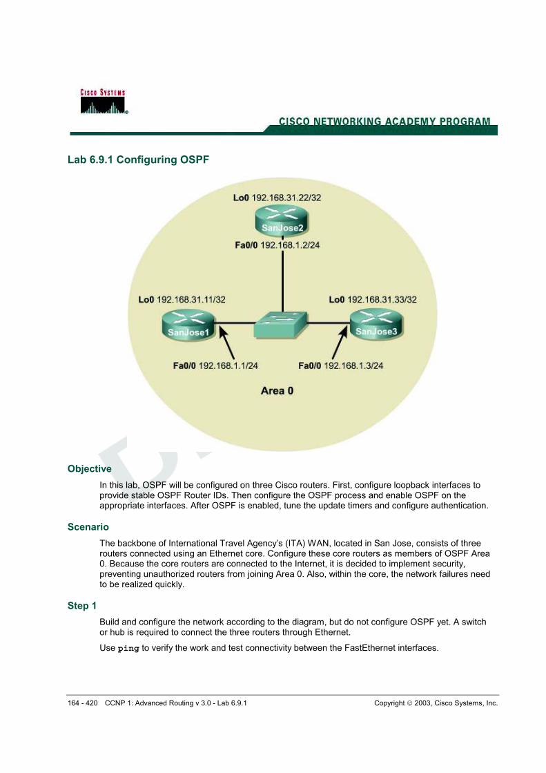
The backbone of International Travel Agency’s (ITA) WAN, located in San Jose, consists of three routers connected using an Ethernet core. Configure these core routers as members of OSPF Area 0. Because the core routers are connected to the Internet, it is decided to implement security, preventing unauthorized routers from joining Area 0. Also, within the core, the network failures need to be realized quickly.
Step 1
Build and configure the network according to the diagram, but do not configure OSPF yet. A switch or hub is required to connect the three routers through Ethernet.
Use ping to verify the work and test connectivity between the FastEthernet interfaces.
165 - 420 CCNP 1: Advanced Routing v 3.0 - Lab 6.9.1 Copyright 2003, Cisco Systems, Inc.
Step 2
On each router, configure a loopback interface with a unique IP address. Cisco routers use the highest loopback IP address as the OSPF Router ID. In the absence of a loopback interface, the router uses the highest IP address among its active interfaces, which might force a router to change router IDs if an interface goes down. Because loopback interfaces are immune to physical and data link problems, they should be used to derive the router ID. To avoid conflicts with registered network addresses, use private network ranges for the loopback interfaces. Configure the core routers using the following commands:
Now that loopback interfaces are configured, configure OSPF. Use the following commands as an example to configure each router:
SanJose1(config)#router ospf 1 SanJose1(config-router)#network 192.168.1.0 0.0.0.255 area 0
Note: An OSPF process ID is locally significant. It does not need to match neighboring routers. The ID is needed to identify a unique instance of an OSPF database, because multiple processes can run concurrently on a single router.
Step 4
After enabling OSPF routing on each of the three routers, verify its operation using show commands. Several important show commands can be used to gather OSPF information. First, issue the show ip protocols command on any of the three routers, as follows:
SanJose1#show ip protocols Routing Protocol is "ospf 1" Sending updates every 0 seconds Invalid after 0 seconds, hold down 0, flushed after 0 Outgoing update filter list for all interfaces is Incoming update filter list for all interfaces is Redistributing: ospf 1 Routing for Networks: 192.168.1.0 Routing Information Sources: Gateway Distance Last Update Distance: (default is 110)
Note: The update timers are set to 0. Updates are not sent at regular intervals. Updates are event driven.
Next, use the show ip ospf command, as follows, to get more details about the OSPF
process, including the router ID:
SanJose1#show ip ospf Routing Process "ospf 1" with ID 192.168.31.11 Supports only single TOS(TOS0) routes SPF schedule delay 5 secs, Hold time between two SPFs 10 secs Minimum LSA interval 5 secs. Minimum LSA arrival 1 secs
166 - 420 CCNP 1: Advanced Routing v 3.0 - Lab 6.9.1 Copyright 2003, Cisco Systems, Inc.
Number of external LSA 0. Checksum Sum 0x0 Number of DCbitless external LSA 0 Number of DoNotAge external LSA 0 Number of areas in this router is 1. 1 normal 0 stub 0 nssa External flood list length 0 Area BACKBONE(0) Number of interfaces in this area is 1 Area has no authentication SPF algorithm executed 5 times Area ranges are Number of LSA 4. Checksum Sum 0x1CAC4 Number of DCbitless LSA 0 Number of indication LSA 0 Number of DoNotAge LSA 0 Flood list length 0
1. What address is the router using as its router ID?
SanJose1 is using 192.168.31.11, SanJose2 is using 192.168.31.22, and SanJose3 is using 192.168.31.33.
The loopback interface should be seen as the router ID. To see the OSPF neighbors, use the show ip ospf neighbor command. The output of this command displays all known OSPF neighbors, including their router IDs, their interface addresses, and their adjacency status. Also issue the show ip ospf neighbor detail command, which outputs even more information as follows:
SanJose1#show ip ospf neighbor Neighbor ID Pri State Dead Time Address Interface 192.168.31.22 1 FULL/BDR 00:00:36 192.168.1.2 FastEthernet0/0 192.168.31.33 1 FULL/DR 00:00:33 192.168.1.3 FastEthernet0/0 SanJose1#show ip ospf neighbor detail Neighbor 192.168.31.22, interface address 192.168.1.2 In the area 0 via interface FastEthernet0/0 Neighbor priority is 1, State is FULL, 6 state changes DR is 192.168.1.3 BDR is 192.168.1.2 Options 2 Dead timer due in 00:00:34 Index 2/2, retransmission queue length 0, number of retransmission 2 First 0x0(0)/0x0(0) Next 0x0(0)/0x0(0) Last retransmission scan length is 1, maximum is 1 Last retransmission scan time is 0 msec, maximum is 0 msec Neighbor 192.168.31.33, interface address 192.168.1.3 In the area 0 via interface FastEthernet0/0 Neighbor priority is 1, State is FULL, 6 state changes DR is 192.168.1.3 BDR is 192.168.1.2 Options 2 Dead timer due in 00:00:30 Index 1/1, retransmission queue length 0, number of retransmission 1 First 0x0(0)/0x0(0) Next 0x0(0)/0x0(0) Last retransmission scan length is 1, maximum is 1 Last retransmission scan time is 0 msec, maximum is 0 msec
2. Based on the output of this command, which router is the Designated Router (DR) on this network?
192.168.1.3 (SanJose3)
167 - 420 CCNP 1: Advanced Routing v 3.0 - Lab 6.9.1 Copyright 2003, Cisco Systems, Inc.
3. Which router is the Backup Designated Router (BDR)?
192.168.1.2 (SanJose2)
Most likely, the router with the highest router ID is the DR, the router with the second-highest router ID is the BDR, and the other router is a DROTHER.
Because each interface on a given router is connected to a different network, some of the key OSPF information is interface specific. Issue the show ip ospf interface command for the FastEthernet interface on the router as follows:
SanJose1#show ip ospf interface fa0/0 FastEthernet0/0 is up, line protocol is up Internet Address 192.168.1.1/24, Area 0 Process ID 1, Router ID 192.168.31.11, Network Type BROADCAST, Cost: 1 Transmit Delay is 1 sec, State DROTHER, Priority 1 Designated Router (ID) 192.168.31.33, Interface address 192.168.1.3 Backup Designated router (ID) 192.168.31.22, Interface address 192.168.1.2 Timer intervals configured, Hello 10, Dead 40, Wait 40, Retransmit 5 Hello due in 00:00:09 Index 1/1, flood queue length 0 Next 0x0(0)/0x0(0) Last flood scan length is 0, maximum is 1 Last flood scan time is 0 msec, maximum is 0 msec Neighbor Count is 2, Adjacent neighbor count is 2 Adjacent with neighbor 192.168.31.22 (Backup Designated Router) Adjacent with neighbor 192.168.31.33 (Designated Router) Suppress hello for 0 neighbor(s)
4. Based on the output of this command, what OSPF network type is the Ethernet interface on the router connected to?
The network type is broadcast.
5. What is the Hello update timer set to?
The Hello update timer is set to 10 seconds.
6. What is the Dead timer set to?
The Dead timer is set to 40 seconds.
Ethernet networks are known to OSPF as broadcast networks. The default timer values are ten (10) second hello updates and 40 second dead intervals.
Step 5
It is decided to adjust OSPF timers so that the core routers will detect network failures in less time. This will increase traffic, but this is less of a concern on the high speed core Ethernet segment than on a busy WAN link. It is also decided that the need for quick convergence at the core outweighs the extra traffic. Manually change the Hello and Dead intervals on SanJose1 as follows:
168 - 420 CCNP 1: Advanced Routing v 3.0 - Lab 6.9.1 Copyright 2003, Cisco Systems, Inc.
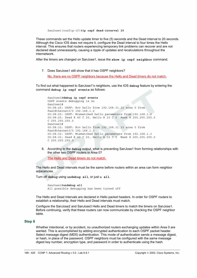
SanJose1(config-if)#ip ospf dead-interval 20
These commands set the Hello update timer to five (5) seconds and the Dead interval to 20 seconds. Although the Cisco IOS does not require it, configure the Dead interval to four times the Hello interval. This ensures that routers experiencing temporary link problems can recover and are not declared dead unnecessarily, causing a ripple of updates and recalculations throughout the internetwork.
After the timers are changed on SanJose1, issue the show ip ospf neighbor command.
7. Does SanJose1 still show that it has OSPF neighbors?
No, there are no OSPF neighbors because the Hello and Dead timers do not match.
To find out what happened to SanJose1’s neighbors, use the IOS debug feature by entering the
command debug ip ospf events as follows:
SanJose1#debug ip ospf events OSPF events debugging is on SanJose1# 00:08:25: OSPF: Rcv hello from 192.168.31.22 area 0 from FastEthernet0/0 192.168.1.2 00:08:25: OSPF: Mismatched hello parameters from 192.168.1.2 00:08:25: Dead R 40 C 20, Hello R 10 C 5 Mask R 255.255.255.0 C 255.255.255.0 SanJose1# 00:08:32: OSPF: Rcv hello from 192.168.31.33 area 0 from FastEthernet0/0 192.168.1.3 00:08:32: OSPF: Mismatched hello parameters from 192.168.1.3 00:08:32: Dead R 40 C 20, Hello R 10 C 5 Mask R 255.255.255.0 C 255.255.255.0
8. According to the debug output, what is preventing SanJose1 from forming relationships with the other two OSPF routers in Area 0?
The Hello and Dead timers do not match.
The Hello and Dead intervals must be the same before routers within an area can form neighbor adjacencies.
Turn off debug using undebug all, or just u all.
SanJose1#undebug all All possible debugging has been turned off
The Hello and Dead intervals are declared in Hello packet headers. In order for OSPF routers to establish a relationship, their Hello and Dead intervals must match.
Configure the SanJose2 and SanJose3 Hello and Dead timers to match the timers on SanJose1. Before continuing, verify that these routers can now communicate by checking the OSPF neighbor table.
Step 6
Whether intentional, or by accident, no unauthorized routers exchanging updates within Area 0 are wanted. This is accomplished by adding encrypted authentication to each OSPF packet header. Select message digest (MD5) authentication. This mode of authentication sends a message digest, or hash, in place of the password. OSPF neighbors must be configured with the same message digest key number, encryption type, and password in order to authenticate using the hash.
169 - 420 CCNP 1: Advanced Routing v 3.0 - Lab 6.9.1 Copyright 2003, Cisco Systems, Inc.
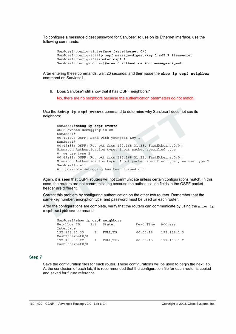
To configure a message digest password for SanJose1 to use on its Ethernet interface, use the following commands:
After entering these commands, wait 20 seconds, and then issue the show ip ospf neighbor command on SanJose1.
9. Does SanJose1 still show that it has OSPF neighbors?
No, there are no neighbors because the authentication parameters do not match.
Use the debug ip ospf events command to determine why SanJose1 does not see its neighbors:
SanJose1#debug ip ospf events OSPF events debugging is on SanJose1# 00:49:32: OSPF: Send with youngest Key 1 SanJose1# 00:49:33: OSPF: Rcv pkt from 192.168.31.33, FastEthernet0/0 : Mismatch Authentication type. Input packet specified type 0, we use type 2 00:49:33: OSPF: Rcv pkt from 192.168.31.22, FastEthernet0/0 : Mismatch Authentication type. Input packet specified type , we use type 2 SanJose1#u all All possible debugging has been turned off
Again, it is seen that OSPF routers will not communicate unless certain configurations match. In this case, the routers are not communicating because the authentication fields in the OSPF packet header are different.
Correct this problem by configuring authentication on the other two routers. Remember that the same key number, encryption type, and password must be used on each router.
After the configurations are complete, verify that the routers can communicate by using the show ip ospf neighbors command.
SanJose1#show ip ospf neighbors Neighbor ID Pri State Dead Time Address Interface 192.168.31.33 1 FULL/DR 00:00:16 192.168.1.3 FastEthernet0/0 192.168.31.22 1 FULL/BDR 00:00:15 192.168.1.2 FastEthernet0/0
Step 7
Save the configuration files for each router. These configurations will be used to begin the next lab. At the conclusion of each lab, it is recommended that the configuration file for each router is copied and saved for future reference.
170 - 420 CCNP 1: Advanced Routing v 3.0 - Lab 6.9.1 Copyright 2003, Cisco Systems, Inc.
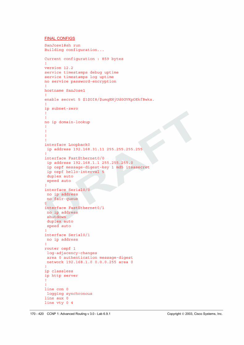
FINAL CONFIGS
SanJose1#sh run Building configuration... Current configuration : 859 bytes ! version 12.2 service timestamps debug uptime service timestamps log uptime no service password-encryption ! hostname SanJose1 ! enable secret 5 $1$OI8/$umqEHjUd0GVKpOEkfBwkx. ! ip subnet-zero ! ! no ip domain-lookup ! ! ! ! interface Loopback0 ip address 192.168.31.11 255.255.255.255 ! interface FastEthernet0/0 ip address 192.168.1.1 255.255.255.0 ip ospf message-digest-key 1 md5 itsasecret ip ospf hello-interval 5 duplex auto speed auto ! interface Serial0/0 no ip address no fair-queue ! interface FastEthernet0/1 no ip address shutdown duplex auto speed auto ! interface Serial0/1 no ip address ! router ospf 1 log-adjacency-changes area 0 authentication message-digest network 192.168.1.0 0.0.0.255 area 0 ! ip classless ip http server ! ! line con 0 logging synchronous line aux 0 line vty 0 4
171 - 420 CCNP 1: Advanced Routing v 3.0 - Lab 6.9.1 Copyright 2003, Cisco Systems, Inc.
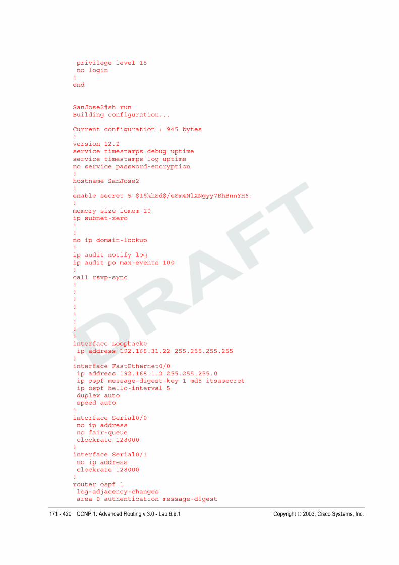
privilege level 15 no login ! end SanJose2#sh run Building configuration... Current configuration : 945 bytes ! version 12.2 service timestamps debug uptime service timestamps log uptime no service password-encryption ! hostname SanJose2 ! enable secret 5 $1$khSd$/eSm4NlXNgyy7BhBnnYH6. ! memory-size iomem 10 ip subnet-zero ! ! no ip domain-lookup ! ip audit notify log ip audit po max-events 100 ! call rsvp-sync ! ! ! ! ! ! ! ! interface Loopback0 ip address 192.168.31.22 255.255.255.255 ! interface FastEthernet0/0 ip address 192.168.1.2 255.255.255.0 ip ospf message-digest-key 1 md5 itsasecret ip ospf hello-interval 5 duplex auto speed auto ! interface Serial0/0 no ip address no fair-queue clockrate 128000 ! interface Serial0/1 no ip address clockrate 128000 ! router ospf 1 log-adjacency-changes area 0 authentication message-digest
172 - 420 CCNP 1: Advanced Routing v 3.0 - Lab 6.9.1 Copyright 2003, Cisco Systems, Inc.
network 192.168.1.0 0.0.0.255 area 0 ! ip classless ip http server ! ! ! dial-peer cor custom ! ! ! ! ! line con 0 logging synchronous line aux 0 line vty 0 4 privilege level 15 no login ! end SanJose3#sh run Building configuration... Current configuration : 1009 bytes ! version 12.2 service timestamps debug uptime service timestamps log uptime no service password-encryption ! hostname SanJose3 ! enable secret 5 $1$viTG$OjXHsX1WF8isRnQCrdu8P/ ! memory-size iomem 10 ip subnet-zero ! ! no ip domain-lookup ! ip audit notify log ip audit po max-events 100 ! call rsvp-sync ! ! ! ! ! ! ! ! interface Loopback0 ip address 192.168.31.33 255.255.255.255 ! interface FastEthernet0/0 ip address 192.168.1.3 255.255.255.0
173 - 420 CCNP 1: Advanced Routing v 3.0 - Lab 6.9.1 Copyright 2003, Cisco Systems, Inc.
ip ospf message-digest-key 1 md5 itsasecret ip ospf hello-interval 5 duplex auto speed auto ! interface Serial0/0 no ip address no fair-queue clockrate 128000 ! interface BRI0/0 no ip address encapsulation hdlc shutdown ! interface Serial0/1 no ip address clockrate 128000 ! router ospf 1 log-adjacency-changes area 0 authentication message-digest network 192.168.1.0 0.0.0.255 area 0 ! ip classless ip http server ! ! ! dial-peer cor custom ! ! ! ! ! line con 0 logging synchronous line aux 0 line vty 0 4 privilege level 15 no login ! end
174 - 420 CCNP 1: Advanced Routing v 3.0 - Lab 6.9.2a Copyright 2003, Cisco Systems, Inc.
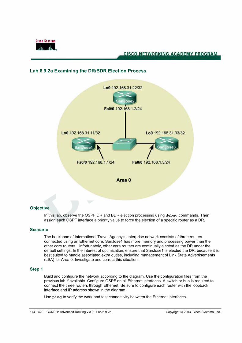
Lab 6.9.2a Examining the DR/BDR Election Process
Objective
In this lab, observe the OSPF DR and BDR election processing using debug commands. Then
assign each OSPF interface a priority value to force the election of a specific router as a DR.
Scenario
The backbone of International Travel Agency’s enterprise network consists of three routers connected using an Ethernet core. SanJose1 has more memory and processing power than the other core routers. Unfortunately, other core routers are continually elected as the DR under the default settings. In the interest of optimization, ensure that SanJose1 is elected the DR, because it is best suited to handle associated extra duties, including management of Link State Advertisements (LSA) for Area 0. Investigate and correct this situation.
Step 1
Build and configure the network according to the diagram. Use the configuration files from the previous lab if available. Configure OSPF on all Ethernet interfaces. A switch or hub is required to connect the three routers through Ethernet. Be sure to configure each router with the loopback interface and IP address shown in the diagram.
Use ping to verify the work and test connectivity between the Ethernet interfaces.
175 - 420 CCNP 1: Advanced Routing v 3.0 - Lab 6.9.2a Copyright 2003, Cisco Systems, Inc.
Step 2
Use the show ip ospf neighbor detail command as follows to verify that the OSPF routers have formed adjacencies:
Note: The routers are still using authentication for the previous lab setup.
SanJose3#show ip ospf neighbor detail Neighbor 192.168.31.11, interface address 192.168.1.1 In the area 0 via interface FastEthernet0/0 Neighbor priority is 1, State is FULL, 12 state changes DR is 192.168.1.3 BDR is 192.168.1.2 Options 2 Dead timer due in 00:00:17 Index 2/2, retransmission queue length 0, number of retransmission 1 First 0x0(0)/0x0(0) Next 0x0(0)/0x0(0) Last retransmission scan length is 1, maximum is 1 Last retransmission scan time is 0 msec, maximum is 0 msec Neighbor 192.168.31.22, interface address 192.168.1.2 In the area 0 via interface FastEthernet0/0 Neighbor priority is 1, State is FULL, 6 state changes DR is 192.168.1.3 BDR is 192.168.1.2 Options 2 Dead timer due in 00:00:15 Index 1/1, retransmission queue length 0, number of retransmission 5 First 0x0(0)/0x0(0) Next 0x0(0)/0x0(0) Last retransmission scan length is 1, maximum is 1 Last retransmission scan time is 0 msec, maximum is 0 msec
1. Which router is the DR? Why?
192.168.1.3 (SanJose3) is the DR because it has the highest router ID.
2. Which router is the BDR? Why?
192.168.1.2 (SanJose2) is the BDR because it has the second highest router ID.
Recall that router IDs determine the DR and BDR.
Step 3
If the network is configured according to the diagram, SanJose1 will not be the DR. Temporarily shut down SanJose3, which has the highest router ID, 192.168.31.33, and observe the DR/BDR election process. To observe the election, issue the following debug command on SanJose1:
SanJose1#debug ip ospf adj
Now that OSPF adjacency events will be logged to SanJose1 console, remove SanJose3 from the OSPF network by shutting down its FastEthernet interface as follows:
SanJose3(config)#interface fastethernet 0/0 SanJose3(config-if)#shutdown Watch the debug output on SanJose1: SanJose1# 00:48:47: OSPF: Rcv hello from 192.168.31.22 area 0 from FastEthernet0/0 192.168.1.2 00:48:47: OSPF: Neighbor change Event on interface FastEthernet0/0 00:48:47: OSPF: DR/BDR election on FastEthernet0/0 00:48:47: OSPF: Elect BDR 192.168.31.11 00:48:47: OSPF: Elect DR 192.168.31.22 00:48:47: OSPF: Elect BDR 192.168.31.11 00:48:47: OSPF: Elect DR 192.168.31.22 00:48:47: DR: 192.168.31.22 (Id) BDR: 192.168.31.11 (Id) 00:48:47: OSPF: Remember old DR 192.168.31.33 (id) 00:48:47: OSPF: End of hello processing
176 - 420 CCNP 1: Advanced Routing v 3.0 - Lab 6.9.2a Copyright 2003, Cisco Systems, Inc.
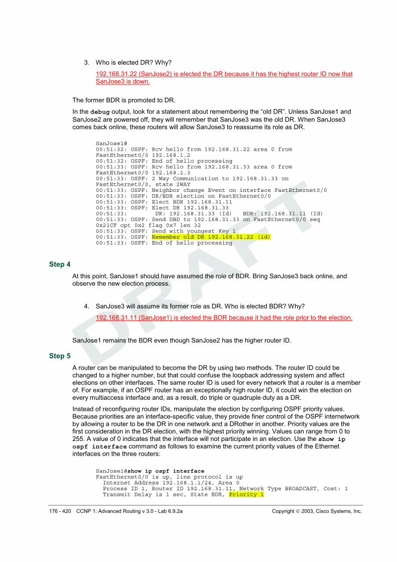
3. Who is elected DR? Why?
192.168.31.22 (SanJose2) is elected the DR because it has the highest router ID now that SanJose3 is down.
The former BDR is promoted to DR.
In the debug output, look for a statement about remembering the “old DR”. Unless SanJose1 and
SanJose2 are powered off, they will remember that SanJose3 was the old DR. When SanJose3 comes back online, these routers will allow SanJose3 to reassume its role as DR.
SanJose1# 00:51:32: OSPF: Rcv hello from 192.168.31.22 area 0 from FastEthernet0/0 192.168.1.2 00:51:32: OSPF: End of hello processing 00:51:33: OSPF: Rcv hello from 192.168.31.33 area 0 from FastEthernet0/0 192.168.1.3 00:51:33: OSPF: 2 Way Communication to 192.168.31.33 on FastEthernet0/0, state 2WAY 00:51:33: OSPF: Neighbor change Event on interface FastEthernet0/0 00:51:33: OSPF: DR/BDR election on FastEthernet0/0 00:51:33: OSPF: Elect BDR 192.168.31.11 00:51:33: OSPF: Elect DR 192.168.31.33 00:51:33: DR: 192.168.31.33 (Id) BDR: 192.168.31.11 (Id) 00:51:33: OSPF: Send DBD to 192.168.31.33 on FastEthernet0/0 seq 0x21CF opt 0x2 flag 0x7 len 32 00:51:33: OSPF: Send with youngest Key 1 00:51:33: OSPF: Remember old DR 192.168.31.22 (id) 00:51:33: OSPF: End of hello processing
Step 4
At this point, SanJose1 should have assumed the role of BDR. Bring SanJose3 back online, and observe the new election process.
4. SanJose3 will assume its former role as DR. Who is elected BDR? Why?
192.168.31.11 (SanJose1) is elected the BDR because it had the role prior to the election.
SanJose1 remains the BDR even though SanJose2 has the higher router ID.
Step 5
A router can be manipulated to become the DR by using two methods. The router ID could be changed to a higher number, but that could confuse the loopback addressing system and affect elections on other interfaces. The same router ID is used for every network that a router is a member of. For example, if an OSPF router has an exceptionally high router ID, it could win the election on every multiaccess interface and, as a result, do triple or quadruple duty as a DR.
Instead of reconfiguring router IDs, manipulate the election by configuring OSPF priority values. Because priorities are an interface-specific value, they provide finer control of the OSPF internetwork by allowing a router to be the DR in one network and a DRother in another. Priority values are the first consideration in the DR election, with the highest priority winning. Values can range from 0 to 255. A value of 0 indicates that the interface will not participate in an election. Use the show ip ospf interface command as follows to examine the current priority values of the Ethernet interfaces on the three routers:
SanJose1#show ip ospf interface FastEthernet0/0 is up, line protocol is up Internet Address 192.168.1.1/24, Area 0 Process ID 1, Router ID 192.168.31.11, Network Type BROADCAST, Cost: 1 Transmit Delay is 1 sec, State BDR, Priority 1
177 - 420 CCNP 1: Advanced Routing v 3.0 - Lab 6.9.2a Copyright 2003, Cisco Systems, Inc.
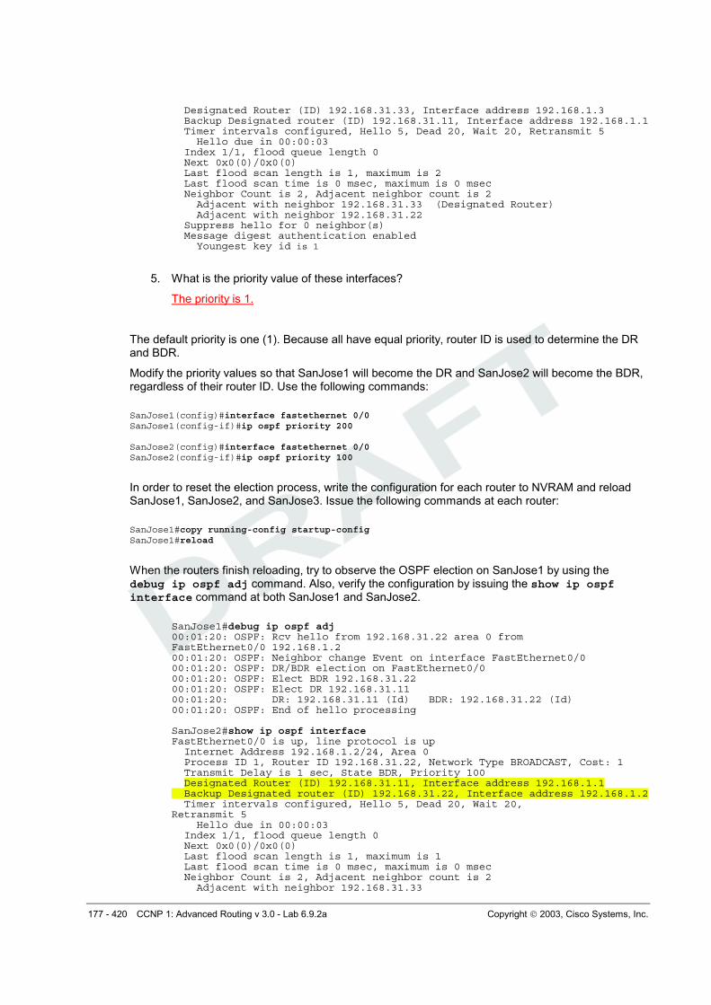
Designated Router (ID) 192.168.31.33, Interface address 192.168.1.3 Backup Designated router (ID) 192.168.31.11, Interface address 192.168.1.1 Timer intervals configured, Hello 5, Dead 20, Wait 20, Retransmit 5 Hello due in 00:00:03 Index 1/1, flood queue length 0 Next 0x0(0)/0x0(0) Last flood scan length is 1, maximum is 2 Last flood scan time is 0 msec, maximum is 0 msec Neighbor Count is 2, Adjacent neighbor count is 2 Adjacent with neighbor 192.168.31.33 (Designated Router) Adjacent with neighbor 192.168.31.22 Suppress hello for 0 neighbor(s) Message digest authentication enabled Youngest key id is 1
5. What is the priority value of these interfaces?
The priority is 1.
The default priority is one (1). Because all have equal priority, router ID is used to determine the DR and BDR.
Modify the priority values so that SanJose1 will become the DR and SanJose2 will become the BDR, regardless of their router ID. Use the following commands:
In order to reset the election process, write the configuration for each router to NVRAM and reload SanJose1, SanJose2, and SanJose3. Issue the following commands at each router:
When the routers finish reloading, try to observe the OSPF election on SanJose1 by using the debug ip ospf adj command. Also, verify the configuration by issuing the show ip ospf interface command at both SanJose1 and SanJose2.
SanJose1#debug ip ospf adj 00:01:20: OSPF: Rcv hello from 192.168.31.22 area 0 from FastEthernet0/0 192.168.1.2 00:01:20: OSPF: Neighbor change Event on interface FastEthernet0/0 00:01:20: OSPF: DR/BDR election on FastEthernet0/0 00:01:20: OSPF: Elect BDR 192.168.31.22 00:01:20: OSPF: Elect DR 192.168.31.11 00:01:20: DR: 192.168.31.11 (Id) BDR: 192.168.31.22 (Id) 00:01:20: OSPF: End of hello processing SanJose2#show ip ospf interface FastEthernet0/0 is up, line protocol is up Internet Address 192.168.1.2/24, Area 0 Process ID 1, Router ID 192.168.31.22, Network Type BROADCAST, Cost: 1 Transmit Delay is 1 sec, State BDR, Priority 100 Designated Router (ID) 192.168.31.11, Interface address 192.168.1.1 Backup Designated router (ID) 192.168.31.22, Interface address 192.168.1.2 Timer intervals configured, Hello 5, Dead 20, Wait 20, Retransmit 5 Hello due in 00:00:03 Index 1/1, flood queue length 0 Next 0x0(0)/0x0(0) Last flood scan length is 1, maximum is 1 Last flood scan time is 0 msec, maximum is 0 msec Neighbor Count is 2, Adjacent neighbor count is 2 Adjacent with neighbor 192.168.31.33
178 - 420 CCNP 1: Advanced Routing v 3.0 - Lab 6.9.2a Copyright 2003, Cisco Systems, Inc.
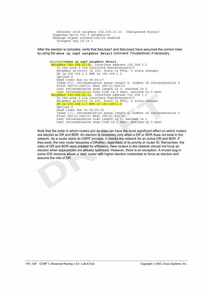
Adjacent with neighbor 192.168.31.11 (Designated Router) Suppress hello for 0 neighbor(s) Message digest authentication enabled Youngest key id is 1
After the election is complete, verify that SanJose1 and SanJose2 have assumed the correct roles by using the show ip ospf neighbor detail command. Troubleshoot, if necessary.
SanJose3#show ip ospf neighbor detail Neighbor 192.168.31.22, interface address 192.168.1.2 In the area 0 via interface FastEthernet0/0 Neighbor priority is 100, State is FULL, 6 state changes DR is 192.168.1.1 BDR is 192.168.1.2 Options 2 Dead timer due in 00:00:17 Index 2/2, retransmission queue length 0, number of retransmission 0 First 0x0(0)/0x0(0) Next 0x0(0)/0x0(0) Last retransmission scan length is 0, maximum is 0 Last retransmission scan time is 0 msec, maximum is 0 msec Neighbor 192.168.31.11, interface address 192.168.1.1 In the area 0 via interface FastEthernet0/0 Neighbor priority is 200, State is FULL, 6 state changes DR is 192.168.1.1 BDR is 192.168.1.2 Options 2 Dead timer due in 00:00:19 Index 1/1, retransmission queue length 0, number of retransmission 2 First 0x0(0)/0x0(0) Next 0x0(0)/0x0(0) Last retransmission scan length is 1, maximum is 1 Last retransmission scan time is 0 msec, maximum is 0 msec
Note that the order in which routers join an area can have the most significant effect on which routers are elected as DR and BDR. An election is necessary only when a DR or BDR does not exist in the network. As a router starts its OSPF process, it checks the network for an active DR and BDR. If they exist, the new router becomes a DRother, regardless of its priority or router ID. Remember, the roles of DR and BDR were created for efficiency. New routers in the network should not force an election when adjacencies are already optimized. However, there is an exception. A known bug in some IOS versions allows a ’new’ router with higher election credentials to force an election and assume the role of DR.
179 - 420 CCNP 1: Advanced Routing v 3.0 - Lab 6.9.2a Copyright 2003, Cisco Systems, Inc.
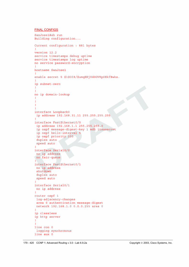
FINAL CONFIGS
SanJose1#sh run Building configuration... Current configuration : 881 bytes ! version 12.2 service timestamps debug uptime service timestamps log uptime no service password-encryption ! hostname SanJose1 ! enable secret 5 $1$OI8/$umqEHjUd0GVKpOEkfBwkx. ! ip subnet-zero ! ! no ip domain-lookup ! ! ! ! interface Loopback0 ip address 192.168.31.11 255.255.255.255 ! interface FastEthernet0/0 ip address 192.168.1.1 255.255.255.0 ip ospf message-digest-key 1 md5 itsasecret ip ospf hello-interval 5 ip ospf priority 200 duplex auto speed auto ! interface Serial0/0 no ip address no fair-queue ! interface FastEthernet0/1 no ip address shutdown duplex auto speed auto ! interface Serial0/1 no ip address ! router ospf 1 log-adjacency-changes area 0 authentication message-digest network 192.168.1.0 0.0.0.255 area 0 ! ip classless ip http server ! ! line con 0 logging synchronous line aux 0
180 - 420 CCNP 1: Advanced Routing v 3.0 - Lab 6.9.2a Copyright 2003, Cisco Systems, Inc.
line vty 0 4 privilege level 15 no login ! end SanJose2#sh run Building configuration... Current configuration : 967 bytes ! version 12.2 service timestamps debug uptime service timestamps log uptime no service password-encryption ! hostname SanJose2 ! enable secret 5 $1$khSd$/eSm4NlXNgyy7BhBnnYH6. ! memory-size iomem 10 ip subnet-zero ! ! no ip domain-lookup ! ip audit notify log ip audit po max-events 100 ! call rsvp-sync ! ! ! ! ! ! ! ! interface Loopback0 ip address 192.168.31.22 255.255.255.255 ! interface FastEthernet0/0 ip address 192.168.1.2 255.255.255.0 ip ospf message-digest-key 1 md5 itsasecret ip ospf hello-interval 5 ip ospf priority 100 duplex auto speed auto ! interface Serial0/0 no ip address no fair-queue clockrate 128000 ! interface Serial0/1 no ip address clockrate 128000 ! router ospf 1
181 - 420 CCNP 1: Advanced Routing v 3.0 - Lab 6.9.2a Copyright 2003, Cisco Systems, Inc.
log-adjacency-changes area 0 authentication message-digest network 192.168.1.0 0.0.0.255 area 0 ! ip classless ip http server ! ! ! dial-peer cor custom ! ! ! ! ! line con 0 logging synchronous line aux 0 line vty 0 4 privilege level 15 no login ! end SanJose3#sh run Building configuration... Current configuration : 1022 bytes ! version 12.2 service timestamps debug uptime service timestamps log uptime no service password-encryption ! hostname SanJose3 ! enable secret 5 $1$viTG$OjXHsX1WF8isRnQCrdu8P/ ! username all memory-size iomem 10 ip subnet-zero ! ! no ip domain-lookup ! ip audit notify log ip audit po max-events 100 ! call rsvp-sync ! ! ! ! ! ! ! ! interface Loopback0
182 - 420 CCNP 1: Advanced Routing v 3.0 - Lab 6.9.2a Copyright 2003, Cisco Systems, Inc.
ip address 192.168.31.33 255.255.255.255 ! interface FastEthernet0/0 ip address 192.168.1.3 255.255.255.0 ip ospf message-digest-key 1 md5 itsasecret ip ospf hello-interval 5 duplex auto speed auto ! interface Serial0/0 no ip address no fair-queue clockrate 128000 ! interface BRI0/0 no ip address encapsulation hdlc shutdown ! interface Serial0/1 no ip address clockrate 128000 ! router ospf 1 log-adjacency-changes area 0 authentication message-digest network 192.168.1.0 0.0.0.255 area 0 ! ip classless ip http server ! ! ! dial-peer cor custom ! ! ! ! ! line con 0 logging synchronous line aux 0 line vty 0 4 privilege level 15 no login ! end
183 - 420 CCNP 1: Advanced Routing v 3.0 - Lab 6.9.2b Copyright 2003, Cisco Systems, Inc.
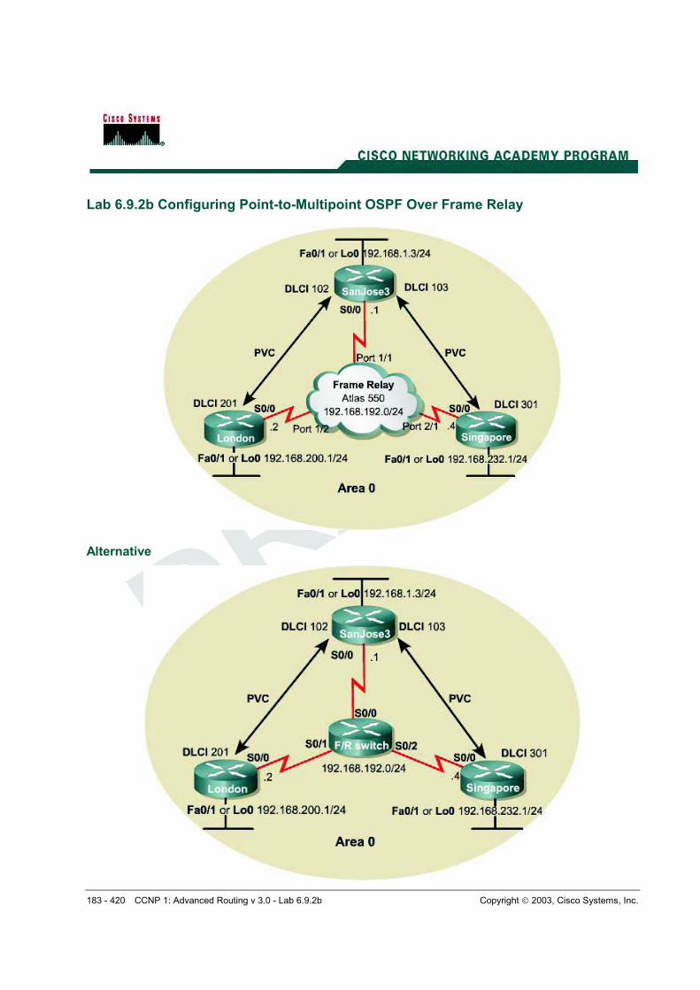
Lab 6.9.2b Configuring Point-to-Multipoint OSPF Over Frame Relay
Alternative
184 - 420 CCNP 1: Advanced Routing v 3.0 - Lab 6.9.2b Copyright 2003, Cisco Systems, Inc.
Objective
In this lab, configure OSPF as a point-to-multipoint network type so that it operates efficiently over a hub-and-spoke Frame Relay topology.
Scenario
International Travel Agency has just connected two regional headquarters to San Jose using Frame Relay in a hub-and-spoke topology. OSPF routing is to be configured over this type of network, which is known for introducing complications into OSPF adjacency relationships. To avoid these complications, manually override the Non-Broadcast Multi-Access (NBMA) OSPF network type and configure OSPF to run as a point-to-multipoint network. In this environment, no DR or BDR is elected.
Step 1
Cable the network according to the diagram. Configure the FastEthernet or Loopback interface for each router as shown, but leave the serial interfaces and OSPF routing unconfigured for now.
Until Frame Relay is configured, ping is not useful for testing connectivity.
Note: This lab requires another router or device to act as a Frame Relay switch. The first diagram assumes that an Adtran Atlas 550 will be used, which is preconfigured. The second diagram assumes that a router will be configured with at least three serial interfaces as a Frame Relay switch. See the configuration at the end of this lab for an example of how to configure a router as a Frame Relay switch. If desired, copy the configuration to a 2600 router for use in this lab.
The Adtran Atlas 550 has a fixed internal configuration that is used for all CCNP 1-4 Version 3.0 labs. The Atlas Frame Relay configuration implements a full mesh topology. To implement a hub-and-spoke topology for this lab, both Frame Relay maps on London reference DLCI 201. Similarly, both Frame Relay maps on Singapore reference DLCI 301. DLCI 201 on London and DLCI 301 on Singapore cause the Atlas to switch frames to the hub router, SanJose3. Using Frame Relay maps on the spoke routers automatically disables Frame Relay inverse ARP on the serial interfaces, thus preventing inadvertent dynamic Frame Relay maps from being formed directly between the spoke routers (which would circumvent the hub router).
Step 2
SanJose3 acts as the hub in this hub-and-spoke network. It reaches London and Singapore through two separate PVCs. Configure Frame Relay on SanJose3’s serial interface shown as follows:
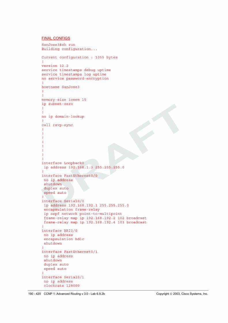
SanJose3(config)#interface serial 0/0 SanJose3(config-if)#encapsulation frame-relay SanJose3(config-if)#ip address 192.168.192.1 255.255.255.0 SanJose3(config-if)#no shutdown SanJose3(config-if)#frame-relay map ip 192.168.192.2 102 broadcast SanJose3(config-if)#frame-relay map ip 192.168.192.4 103 broadcast SanJose3(config-if)#ip ospf network point-to-multipoint
Notice that this configuration includes frame-relay map commands, which are also used on multipoint Frame Relay subinterfaces. These commands are used here with the broadcast keyword so that Frame Relay can process broadcast traffic. Without this configuration, OSPF multicast traffic would not be forwarded correctly by the SanJose3 router.
Configure the serial interface for London as follows:
London(config)#interface serial 0/0 London(config-if)#encapsulation frame-relay London(config-if)#ip address 192.168.192.2 255.255.255.0
185 - 420 CCNP 1: Advanced Routing v 3.0 - Lab 6.9.2b Copyright 2003, Cisco Systems, Inc.
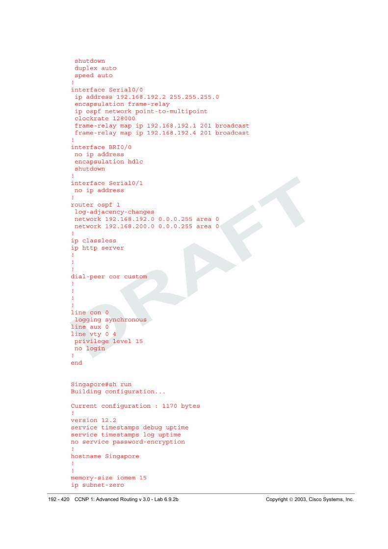
London(config-if)#no shutdown London(config-if)#frame-relay map ip 192.168.192.1 201 broadcast London(config-if)#frame-relay map ip 192.168.192.4 201 broadcast London(config-if)#ip ospf network point-to-multipoint
Finally, configure the serial interface for Singapore as follows: Singapore(config)#interface serial 0/0 Singapore(config-if)#encapsulation frame-relay Singapore(config-if)#ip address 192.168.192.4 255.255.255.0 Singapore(config-if)#no shutdown Singapore(config-if)#frame-relay map ip 192.168.192.1 301 broadcast Singapore(config-if)#frame-relay map ip 192.168.192.2 301 broadcast Singapore(config-if)#ip ospf network point-to-multipoint
Verify Frame Relay operation with a ping command from each router to the other two. Use show
frame-relay pvc and show frame-relay map to troubleshoot connectivity problems. Rebooting the Frame Relay switch might also solve connectivity issues.
SanJose3#show frame-relay pvc PVC Statistics for interface Serial0/0 (Frame Relay DTE) Active Inactive Deleted Static Local 2 0 0 0 Switched 0 0 0 0 Unused 0 1 0 0 DLCI = 102, DLCI USAGE = LOCAL, PVC STATUS = ACTIVE, INTERFACE = Serial0/0 input pkts 111 output pkts 112 in bytes 10936 out bytes 6259 dropped pkts 0 in pkts dropped 0 out pkts dropped 0 out bytes dropped 0 in FECN pkts 0 in BECN pkts 0 out FECN pkts 0 out BECN pkts 0 in DE pkts 0 out DE pkts 0 out bcast pkts 19 out bcast bytes 1428 pvc create time 00:10:58, last time pvc status changed 00:08:38 DLCI = 103, DLCI USAGE = LOCAL, PVC STATUS = ACTIVE, INTERFACE = Serial0/0 input pkts 65 output pkts 56 in bytes 5136 out bytes 3752 dropped pkts 0 in pkts dropped 0 out pkts dropped 0 out bytes dropped 0 in FECN pkts 0 in BECN pkts 0 out FECN pkts 0 out BECN pkts 0 in DE pkts 0 out DE pkts 0 out bcast pkts 19 out bcast bytes 1428 pvc create time 00:11:01, last time pvc status changed 00:08:41 DLCI = 104, DLCI USAGE = UNUSED, PVC STATUS = INACTIVE, INTERFACE = Serial0/0 input pkts 0 output pkts 0 in bytes 0 out bytes 0 dropped pkts 0 in pkts dropped 0 out pkts dropped 0 out bytes dropped 0 in FECN pkts 0 in BECN pkts 0 out FECN pkts 0 out BECN pkts 0 in DE pkts 0 out DE pkts 0 out bcast pkts 0 out bcast bytes 0 switched pkts 0 Detailed packet drop counters: no out intf 0 out intf down 0 no out PVC 0 in PVC down 0 out PVC down 0 pkt too big 0 shaping Q full 0 pkt above DE 0 policing drop 0 pvc create time 00:10:22, last time pvc status changed 00:09:49 SanJose3#show frame-relay map Serial0/0 (up): ip 192.168.192.2 dlci 102(0x66,0x1860), static, broadcast, CISCO, status defined, active
186 - 420 CCNP 1: Advanced Routing v 3.0 - Lab 6.9.2b Copyright 2003, Cisco Systems, Inc.
Serial0/0 (up): ip 192.168.192.4 dlci 103(0x67,0x1870), static, broadcast, CISCO, status defined, active
Step 3
Configure OSPF to run over this point-to-multipoint network. Issue the following commands at the appropriate router:
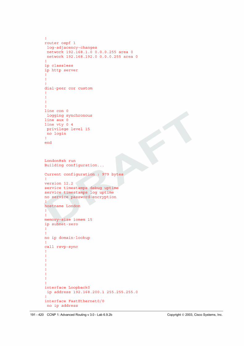
London(config)#router ospf 1 London(config-router)#network 192.168.200.0 0.0.0.255 area 0 London(config-router)#network 192.168.192.0 0.0.0.255 area 0
SanJose3(config)#router ospf 1 SanJose3(config-router)#network 192.168.1.0 0.0.0.255 area 0 SanJose3(config-router)#network 192.168.192 0.0.0.255 area 0
Singapore(config)#router ospf 1 Singapore(config-router)#network 192.168.232.0 0.0.0.255 area 0 Singapore(config-router)#network 192.168.192.0 0.0.0.255 area 0
Verify the OSPF configuration by issuing the show ip route command at each of the routers:
London#show ip route Codes: C - connected, S - static, I - IGRP, R - RIP, M - mobile, B - BGP D - EIGRP, EX - EIGRP external, O - OSPF, IA - OSPF inter area N1 - OSPF NSSA external type 1, N2 - OSPF NSSA external type 2 E1 - OSPF external type 1, E2 - OSPF external type 2, E - EGP i - IS-IS, L1 - IS-IS level-1, L2 - IS-IS level-2, ia - IS-IS inter area * - candidate default, U - per-user static route, o - ODR P - periodic downloaded static route Gateway of last resort is not set 192.168.192.0/24 is variably subnetted, 3 subnets, 2 masks C 192.168.192.0/24 is directly connected, Serial0/0 O 192.168.192.1/32 [110/781] via 192.168.192.1, 00:10:04, Serial0/0 O 192.168.192.4/32 [110/845] via 192.168.192.1, 00:10:04, Serial0/0 C 192.168.200.0/24 is directly connected, Loopback0 192.168.232.0/32 is subnetted, 1 subnets O 192.168.232.1 [110/846] via 192.168.192.1, 00:10:04, Serial0/0 192.168.1.0/32 is subnetted, 1 subnets O 192.168.1.3 [110/782] via 192.168.192.1, 00:10:04, Serial0/0
If each router has a complete table, including routes to 192.168.1.0 /24, 192.168.200.0 /24, and 192.168.232.0 /24, OSPF has been successfully configured to operate over Frame Relay.
Test these routes by pinging the FastEthernet interfaces of each router from London’s console.
Finally, issue the show ip ospf neighbor detail command at any router console:
SanJose3#show ip ospf neighbor Neighbor ID Pri State Dead Time Address Interface 192.168.200.1 1 FULL/ - 00:01:39 192.168.192.2 Serial0/0 192.168.232.1 1 FULL/ - 00:01:36 192.168.192.4 Serial0/0
SanJose3#show ip ospf neighbor detail Neighbor 192.168.200.1, interface address 192.168.192.2 In the area 0 via interface Serial0/0 Neighbor priority is 1, State is FULL, 6 state changes DR is 0.0.0.0 BDR is 0.0.0.0 Options is 0x42 Dead timer due in 00:01:49 Neighbor is up for 00:12:25 Index 2/2, retransmission queue length 0, number of retransmission 1 First 0x0(0)/0x0(0) Next 0x0(0)/0x0(0) Last retransmission scan length is 1, maximum is 1
187 - 420 CCNP 1: Advanced Routing v 3.0 - Lab 6.9.2b Copyright 2003, Cisco Systems, Inc.
Last retransmission scan time is 0 msec, maximum is 0 msec Neighbor 192.168.232.1, interface address 192.168.192.4 In the area 0 via interface Serial0/0 Neighbor priority is 1, State is FULL, 6 state changes DR is 0.0.0.0 BDR is 0.0.0.0 Options is 0x42 Dead timer due in 00:01:46 Neighbor is up for 00:12:25 Index 1/1, retransmission queue length 0, number of retransmission 1 First 0x0(0)/0x0(0) Next 0x0(0)/0x0(0) Last retransmission scan length is 1, maximum is 1 Last retransmission scan time is 0 msec, maximum is 0 msec
1. Is there a DR for this network? Why or why not?
There is no DR for the network because the OSPF network type is point-to-multipoint. Configuring the OSPF point-to-multipoint network type on serial interfaces creates a logical multi-access network over physical point-to-point links. No efficiency would be realized by electing a DR.
There is no DR. The configuration of OSPF point-to-multipoint network type on serial interfaces creates a logical multi-access network over physical point-to-point links. No efficiency would be realized by electing a DR.
188 - 420 CCNP 1: Advanced Routing v 3.0 - Lab 6.9.2b Copyright 2003, Cisco Systems, Inc.
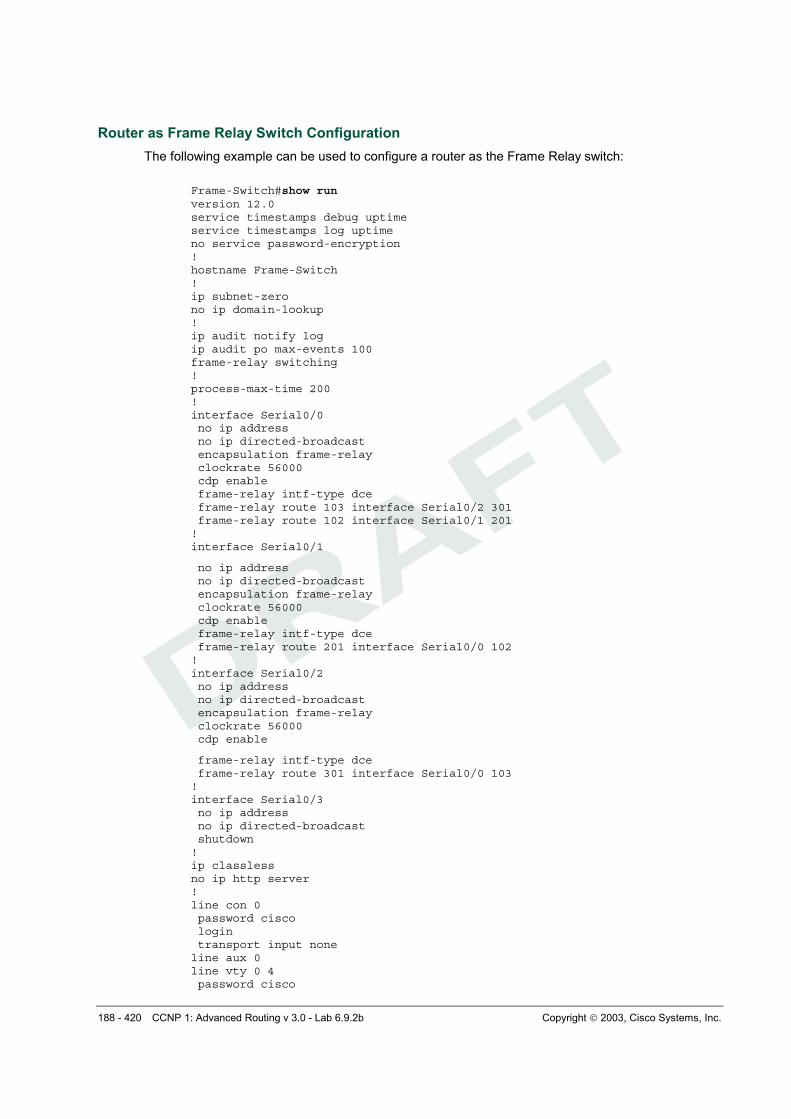
Router as Frame Relay Switch Configuration
The following example can be used to configure a router as the Frame Relay switch:
Frame-Switch#show run version 12.0 service timestamps debug uptime service timestamps log uptime no service password-encryption ! hostname Frame-Switch ! ip subnet-zero no ip domain-lookup ! ip audit notify log ip audit po max-events 100 frame-relay switching ! process-max-time 200 ! interface Serial0/0 no ip address no ip directed-broadcast encapsulation frame-relay clockrate 56000 cdp enable frame-relay intf-type dce frame-relay route 103 interface Serial0/2 301 frame-relay route 102 interface Serial0/1 201 ! interface Serial0/1
no ip address no ip directed-broadcast encapsulation frame-relay clockrate 56000 cdp enable frame-relay intf-type dce frame-relay route 201 interface Serial0/0 102 ! interface Serial0/2 no ip address no ip directed-broadcast encapsulation frame-relay clockrate 56000 cdp enable
frame-relay intf-type dce frame-relay route 301 interface Serial0/0 103 ! interface Serial0/3 no ip address no ip directed-broadcast shutdown ! ip classless no ip http server ! line con 0 password cisco login transport input none line aux 0 line vty 0 4 password cisco
189 - 420 CCNP 1: Advanced Routing v 3.0 - Lab 6.9.2b Copyright 2003, Cisco Systems, Inc.
login ! no scheduler allocate end
190 - 420 CCNP 1: Advanced Routing v 3.0 - Lab 6.9.2b Copyright 2003, Cisco Systems, Inc.
FINAL CONFIGS
SanJose3#sh run Building configuration... Current configuration : 1055 bytes ! version 12.2 service timestamps debug uptime service timestamps log uptime no service password-encryption ! hostname SanJose3 ! ! memory-size iomem 15 ip subnet-zero ! ! no ip domain-lookup ! call rsvp-sync ! ! ! ! ! ! ! ! interface Loopback0 ip address 192.168.1.3 255.255.255.0 ! interface FastEthernet0/0 no ip address shutdown duplex auto speed auto ! interface Serial0/0 ip address 192.168.192.1 255.255.255.0 encapsulation frame-relay ip ospf network point-to-multipoint frame-relay map ip 192.168.192.2 102 broadcast frame-relay map ip 192.168.192.4 103 broadcast ! interface BRI0/0 no ip address encapsulation hdlc shutdown ! interface FastEthernet0/1 no ip address shutdown duplex auto speed auto ! interface Serial0/1 no ip address clockrate 128000
191 - 420 CCNP 1: Advanced Routing v 3.0 - Lab 6.9.2b Copyright 2003, Cisco Systems, Inc.
! router ospf 1 log-adjacency-changes network 192.168.1.0 0.0.0.255 area 0 network 192.168.192.0 0.0.0.255 area 0 ! ip classless ip http server ! ! ! dial-peer cor custom ! ! ! ! line con 0 logging synchronous line aux 0 line vty 0 4 privilege level 15 no login ! end London#sh run Building configuration... Current configuration : 979 bytes ! version 12.2 service timestamps debug uptime service timestamps log uptime no service password-encryption ! hostname London ! ! memory-size iomem 15 ip subnet-zero ! ! no ip domain-lookup ! call rsvp-sync ! ! ! ! ! ! ! ! interface Loopback0 ip address 192.168.200.1 255.255.255.0 ! interface FastEthernet0/0 no ip address
192 - 420 CCNP 1: Advanced Routing v 3.0 - Lab 6.9.2b Copyright 2003, Cisco Systems, Inc.
shutdown duplex auto speed auto ! interface Serial0/0 ip address 192.168.192.2 255.255.255.0 encapsulation frame-relay ip ospf network point-to-multipoint clockrate 128000 frame-relay map ip 192.168.192.1 201 broadcast frame-relay map ip 192.168.192.4 201 broadcast ! interface BRI0/0 no ip address encapsulation hdlc shutdown ! interface Serial0/1 no ip address ! router ospf 1 log-adjacency-changes network 192.168.192.0 0.0.0.255 area 0 network 192.168.200.0 0.0.0.255 area 0 ! ip classless ip http server ! ! ! dial-peer cor custom ! ! ! ! line con 0 logging synchronous line aux 0 line vty 0 4 privilege level 15 no login ! end Singapore#sh run Building configuration... Current configuration : 1170 bytes ! version 12.2 service timestamps debug uptime service timestamps log uptime no service password-encryption ! hostname Singapore ! ! memory-size iomem 15 ip subnet-zero
193 - 420 CCNP 1: Advanced Routing v 3.0 - Lab 6.9.2b Copyright 2003, Cisco Systems, Inc.
! ! no ip domain-lookup ! call rsvp-sync ! ! ! ! ! ! ! ! interface Loopback0 ip address 192.168.232.1 255.255.255.0 ! interface FastEthernet0/0 no ip address shutdown duplex auto speed auto ! interface Serial0/0 ip address 192.168.192.4 255.255.255.0 encapsulation frame-relay ip ospf network point-to-multipoint frame-relay map ip 192.168.192.1 301 broadcast frame-relay map ip 192.168.192.2 301 broadcast ! interface BRI0/0 no ip address encapsulation hdlc shutdown ! interface Serial0/1 no ip address clockrate 128000 ! interface Serial1/0 no ip address shutdown ! interface Serial1/1 no ip address shutdown ! interface Serial1/2 no ip address shutdown ! interface Serial1/3 no ip address shutdown ! router ospf 1 log-adjacency-changes network 192.168.192.0 0.0.0.255 area 0 network 192.168.232.0 0.0.0.255 area 0 ! ip classless
194 - 420 CCNP 1: Advanced Routing v 3.0 - Lab 6.9.2b Copyright 2003, Cisco Systems, Inc.
ip http server ! ! ! dial-peer cor custom ! ! ! ! line con 0 logging synchronous line aux 0 line vty 0 4 privilege level 15 no login ! end
195 - 420 CCNP 1: Advanced Routing v 3.0 - Lab 6.9.3 Copyright 2003, Cisco Systems, Inc.
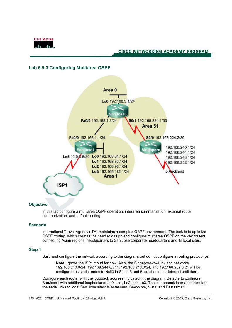
Lab 6.9.3 Configuring Multiarea OSPF
Objective
In this lab configure a multiarea OSPF operation, interarea summarization, external route summarization, and default routing.
Scenario
International Travel Agency (ITA) maintains a complex OSPF environment. The task is to optimize OSPF routing, which creates the need to design and configure multiarea OSPF on the key routers connecting Asian regional headquarters to San Jose corporate headquarters and its local sites.
Step 1
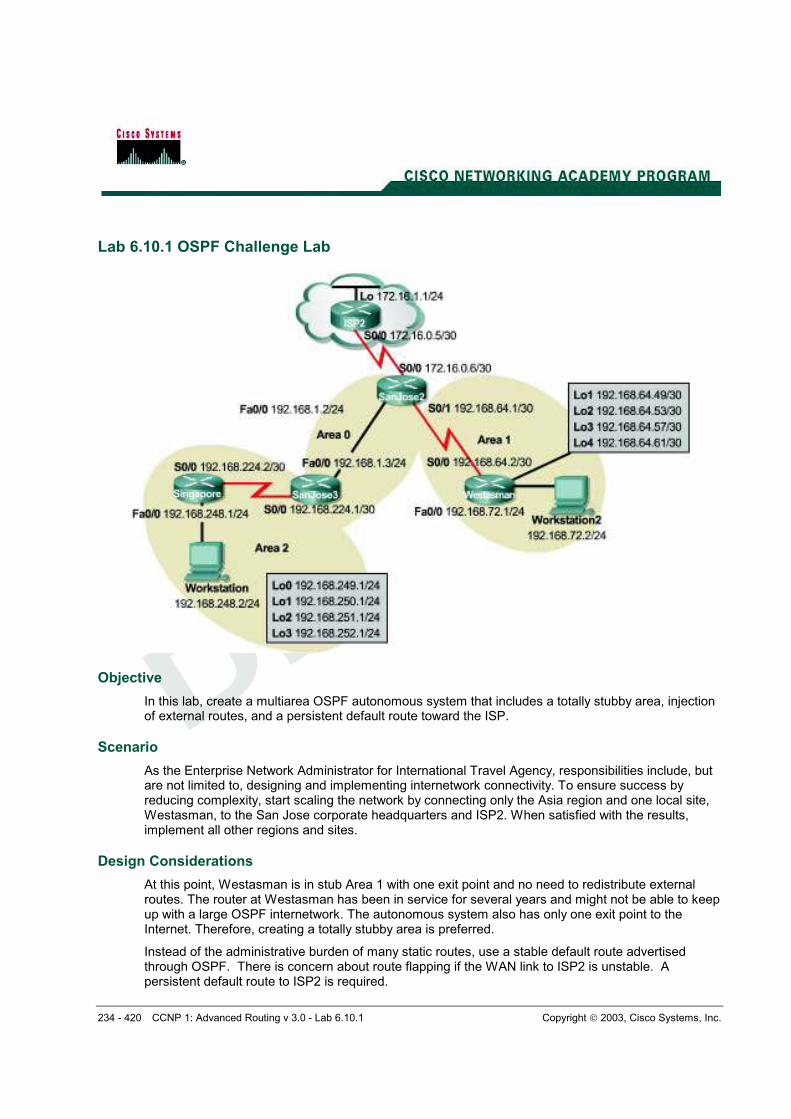
Build and configure the network according to the diagram, but do not configure a routing protocol yet.
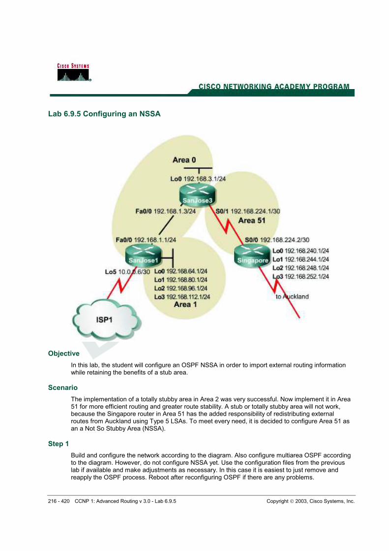
Note: Ignore the ISP1 cloud for now. Also, the Singapore-to-Auckland networks 192.168.240.0/24, 192.168.244.0/244, 192.168.248.0/24, and 192.168.252.0/24 will be configured as static routes to Null0 in Steps 5 and 6, so should be deferred until then.
Configure each router with the loopback address indicated in the diagram. Be sure to configure SanJose1 with additional loopbacks of Lo0, Lo1, Lo2, and Lo3. These loopback interfaces simulate the serial links to local San Jose sites: Westasman, Baypointe, Vista, and Eastasman.
196 - 420 CCNP 1: Advanced Routing v 3.0 - Lab 6.9.3 Copyright 2003, Cisco Systems, Inc.
Use ping to test connectivity between all interfaces. Each router should be able to ping its link partner.
Step 2
Configure multiarea OSPF. On SanJose1, configure FastEthernet 0/0 as a member of Area 0 and all other interfaces as members of Area 1 by using the following commands:
SanJose1(config)#router ospf 1 SanJose1(config-router)#network 192.168.1.0 0.0.0.255 area 0 SanJose1(config-router)#network 192.168.64.0 0.0.63.255 area 1
The last command conveniently enables all loopback interfaces on SanJose1 to participate in the OSPF process.
On SanJose3, configure E0 and Lo0 as members of Area 0, but configure Serial 0/0 as part of Area 51 as follows:
SanJose3(config)#router ospf 1 SanJose3(config-router)#network 192.168.1.0 0.0.0.255 area 0 SanJose3(config-router)#network 192.168.224.0 0.0.0.3 area 51 SanJose3(config-router)#network 192.168.3.0 0.0.0.255 area 0
Finally, on Singapore, configure Serial 0/0 to belong to Area 51 as follows:
Singapore(config)#router ospf 1 Singapore(config-router)#network 192.168.224.0 0.0.0.3 area 51
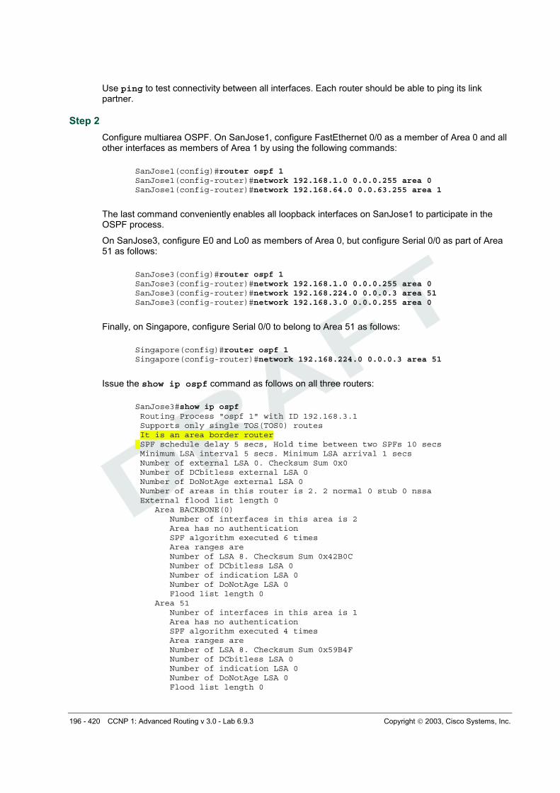
Issue the show ip ospf command as follows on all three routers:
SanJose3#show ip ospf Routing Process "ospf 1" with ID 192.168.3.1 Supports only single TOS(TOS0) routes It is an area border router SPF schedule delay 5 secs, Hold time between two SPFs 10 secs Minimum LSA interval 5 secs. Minimum LSA arrival 1 secs Number of external LSA 0. Checksum Sum 0x0 Number of DCbitless external LSA 0 Number of DoNotAge external LSA 0 Number of areas in this router is 2. 2 normal 0 stub 0 nssa External flood list length 0 Area BACKBONE(0) Number of interfaces in this area is 2 Area has no authentication SPF algorithm executed 6 times Area ranges are Number of LSA 8. Checksum Sum 0x42B0C Number of DCbitless LSA 0 Number of indication LSA 0 Number of DoNotAge LSA 0 Flood list length 0 Area 51 Number of interfaces in this area is 1 Area has no authentication SPF algorithm executed 4 times Area ranges are Number of LSA 8. Checksum Sum 0x59B4F Number of DCbitless LSA 0 Number of indication LSA 0 Number of DoNotAge LSA 0 Flood list length 0
197 - 420 CCNP 1: Advanced Routing v 3.0 - Lab 6.9.3 Copyright 2003, Cisco Systems, Inc.
1. According to the output of the show ip ospf command, which of these routers is an ABR?
SanJose3 is an ABR.
Area border routers connect one or more adjacent OSPF areas to the backbone area.
2. Are there any ASBRs?
Yes, Singapore is an ASBR.
Autonomous system border routers connect external, non-OSPF, networks to the OSPF internetwork.
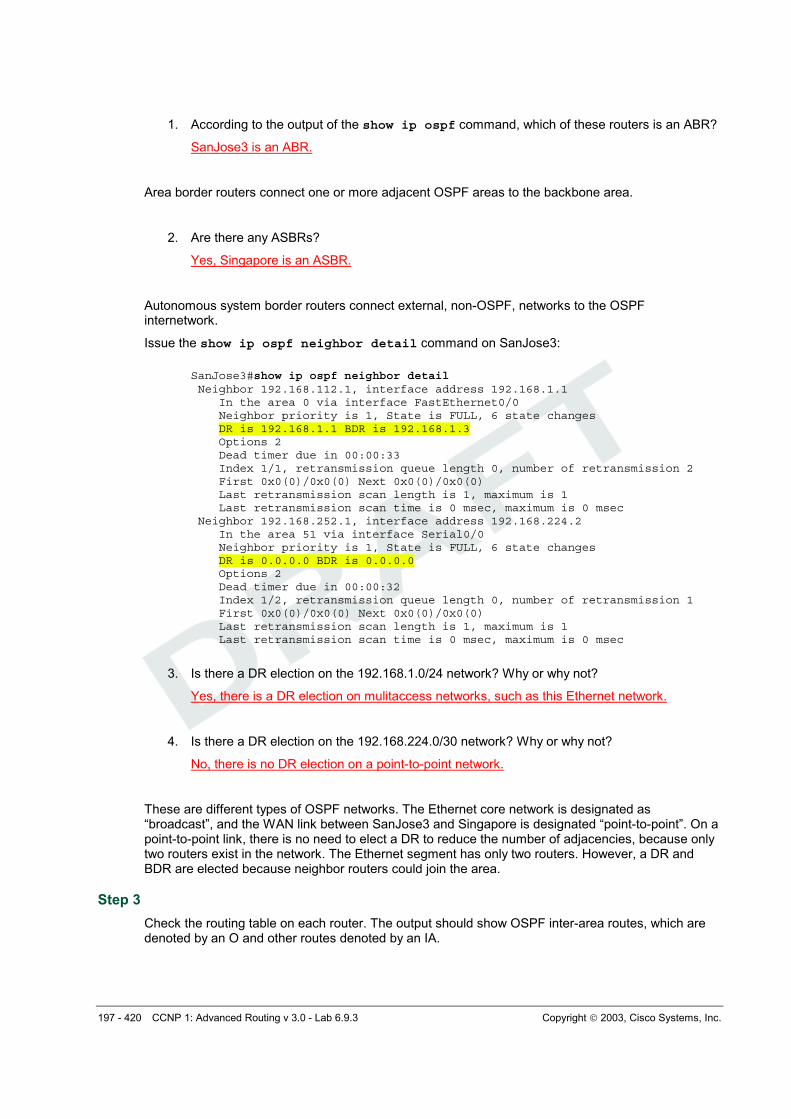
Issue the show ip ospf neighbor detail command on SanJose3:
SanJose3#show ip ospf neighbor detail Neighbor 192.168.112.1, interface address 192.168.1.1 In the area 0 via interface FastEthernet0/0 Neighbor priority is 1, State is FULL, 6 state changes DR is 192.168.1.1 BDR is 192.168.1.3 Options 2 Dead timer due in 00:00:33 Index 1/1, retransmission queue length 0, number of retransmission 2 First 0x0(0)/0x0(0) Next 0x0(0)/0x0(0) Last retransmission scan length is 1, maximum is 1 Last retransmission scan time is 0 msec, maximum is 0 msec Neighbor 192.168.252.1, interface address 192.168.224.2 In the area 51 via interface Serial0/0 Neighbor priority is 1, State is FULL, 6 state changes DR is 0.0.0.0 BDR is 0.0.0.0 Options 2 Dead timer due in 00:00:32 Index 1/2, retransmission queue length 0, number of retransmission 1 First 0x0(0)/0x0(0) Next 0x0(0)/0x0(0) Last retransmission scan length is 1, maximum is 1 Last retransmission scan time is 0 msec, maximum is 0 msec
3. Is there a DR election on the 192.168.1.0/24 network? Why or why not?
Yes, there is a DR election on mulitaccess networks, such as this Ethernet network.
4. Is there a DR election on the 192.168.224.0/30 network? Why or why not?
No, there is no DR election on a point-to-point network.
These are different types of OSPF networks. The Ethernet core network is designated as “broadcast”, and the WAN link between SanJose3 and Singapore is designated “point-to-point”. On a point-to-point link, there is no need to elect a DR to reduce the number of adjacencies, because only two routers exist in the network. The Ethernet segment has only two routers. However, a DR and BDR are elected because neighbor routers could join the area.
Step 3
Check the routing table on each router. The output should show OSPF inter-area routes, which are denoted by an O and other routes denoted by an IA.
198 - 420 CCNP 1: Advanced Routing v 3.0 - Lab 6.9.3 Copyright 2003, Cisco Systems, Inc.
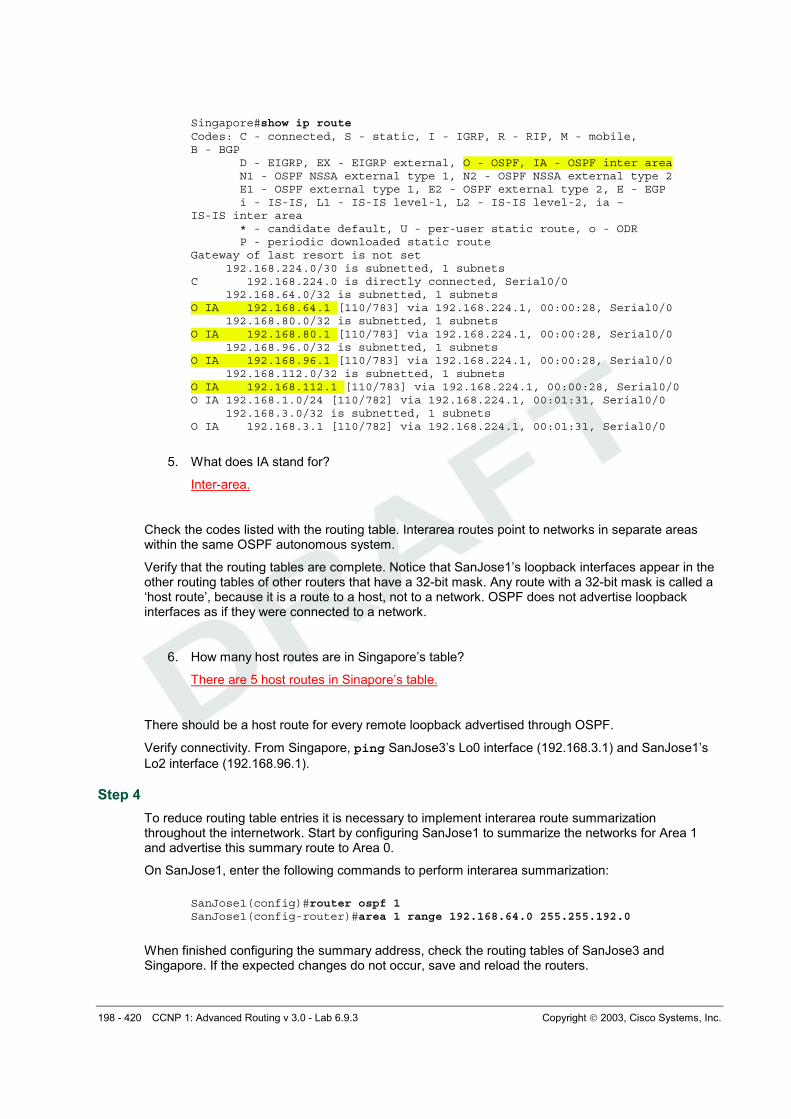
Singapore#show ip route Codes: C - connected, S - static, I - IGRP, R - RIP, M - mobile, B - BGP D - EIGRP, EX - EIGRP external, O - OSPF, IA - OSPF inter area N1 - OSPF NSSA external type 1, N2 - OSPF NSSA external type 2 E1 - OSPF external type 1, E2 - OSPF external type 2, E - EGP i - IS-IS, L1 - IS-IS level-1, L2 - IS-IS level-2, ia – IS-IS inter area * - candidate default, U - per-user static route, o - ODR P - periodic downloaded static route Gateway of last resort is not set 192.168.224.0/30 is subnetted, 1 subnets C 192.168.224.0 is directly connected, Serial0/0 192.168.64.0/32 is subnetted, 1 subnets O IA 192.168.64.1 [110/783] via 192.168.224.1, 00:00:28, Serial0/0 192.168.80.0/32 is subnetted, 1 subnets O IA 192.168.80.1 [110/783] via 192.168.224.1, 00:00:28, Serial0/0 192.168.96.0/32 is subnetted, 1 subnets O IA 192.168.96.1 [110/783] via 192.168.224.1, 00:00:28, Serial0/0 192.168.112.0/32 is subnetted, 1 subnets O IA 192.168.112.1 [110/783] via 192.168.224.1, 00:00:28, Serial0/0 O IA 192.168.1.0/24 [110/782] via 192.168.224.1, 00:01:31, Serial0/0 192.168.3.0/32 is subnetted, 1 subnets O IA 192.168.3.1 [110/782] via 192.168.224.1, 00:01:31, Serial0/0
5. What does IA stand for?
Inter-area.
Check the codes listed with the routing table. Interarea routes point to networks in separate areas within the same OSPF autonomous system.
Verify that the routing tables are complete. Notice that SanJose1’s loopback interfaces appear in the other routing tables of other routers that have a 32-bit mask. Any route with a 32-bit mask is called a
‘host route’, because it is a route to a host, not to a network. OSPF does not advertise loopback interfaces as if they were connected to a network.
6. How many host routes are in Singapore’s table?
There are 5 host routes in Sinapore’s table.
There should be a host route for every remote loopback advertised through OSPF.
Verify connectivity. From Singapore, ping SanJose3’s Lo0 interface (192.168.3.1) and SanJose1’s
Lo2 interface (192.168.96.1).
Step 4
To reduce routing table entries it is necessary to implement interarea route summarization throughout the internetwork. Start by configuring SanJose1 to summarize the networks for Area 1 and advertise this summary route to Area 0.
On SanJose1, enter the following commands to perform interarea summarization:
SanJose1(config)#router ospf 1 SanJose1(config-router)#area 1 range 192.168.64.0 255.255.192.0
When finished configuring the summary address, check the routing tables of SanJose3 and Singapore. If the expected changes do not occur, save and reload the routers.
199 - 420 CCNP 1: Advanced Routing v 3.0 - Lab 6.9.3 Copyright 2003, Cisco Systems, Inc.
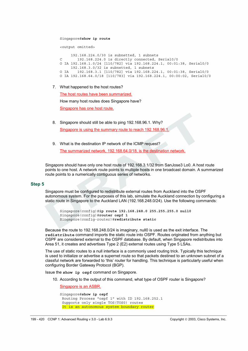
Singapore#show ip route <output omitted> 192.168.224.0/30 is subnetted, 1 subnets C 192.168.224.0 is directly connected, Serial0/0 O IA 192.168.1.0/24 [110/782] via 192.168.224.1, 00:01:38, Serial0/0 192.168.3.0/32 is subnetted, 1 subnets O IA 192.168.3.1 [110/782] via 192.168.224.1, 00:01:38, Serial0/0 O IA 192.168.64.0/18 [110/783] via 192.168.224.1, 00:00:02, Serial0/0
7. What happened to the host routes?
The host routes have been summarized.
How many host routes does Singapore have?
Singapore has one host route.
8. Singapore should still be able to ping 192.168.96.1. Why?
Singapore is using the summary route to reach 192.168.96.1.
9. What is the destination IP network of the ICMP request?
The summarized network, 192.168.64.0/18, is the destination network.
Singapore should have only one host route of 192.168.3.1/32 from SanJose3 Lo0. A host route points to one host. A network route points to multiple hosts in one broadcast domain. A summarized route points to a numerically contiguous series of networks.
Step 5
Singapore must be configured to redistribute external routes from Auckland into the OSPF autonomous system. For the purposes of this lab, simulate the Auckland connection by configuring a static route in Singapore to the Auckland LAN (192.168.248.0/24). Use the following commands:
Because the route to 192.168.248.0/24 is imaginary, null0 is used as the exit interface. The redistribute command imports the static route into OSPF. Routes originated from anything but OSPF are considered external to the OSPF database. By default, when Singapore redistributes into Area 51, it creates and advertises Type 2 (E2) external routes using Type 5 LSAs.
The use of static routes to a null interface is a commonly used routing trick. Typically this technique is used to initialize or advertise a supernet route so that packets destined to an unknown subnet of a classful network are forwarded to ‘this’ router for handling. This technique is particularly useful when configuring Border Gateway Protocol (BGP).
Issue the show ip ospf command on Singapore.
10. According to the output of this command, what type of OSPF router is Singapore?
Singapore is an ASBR. Singapore#show ip ospf Routing Process "ospf 1" with ID 192.168.252.1 Supports only single TOS(TOS0) routes It is an autonomous system boundary router
200 - 420 CCNP 1: Advanced Routing v 3.0 - Lab 6.9.3 Copyright 2003, Cisco Systems, Inc.
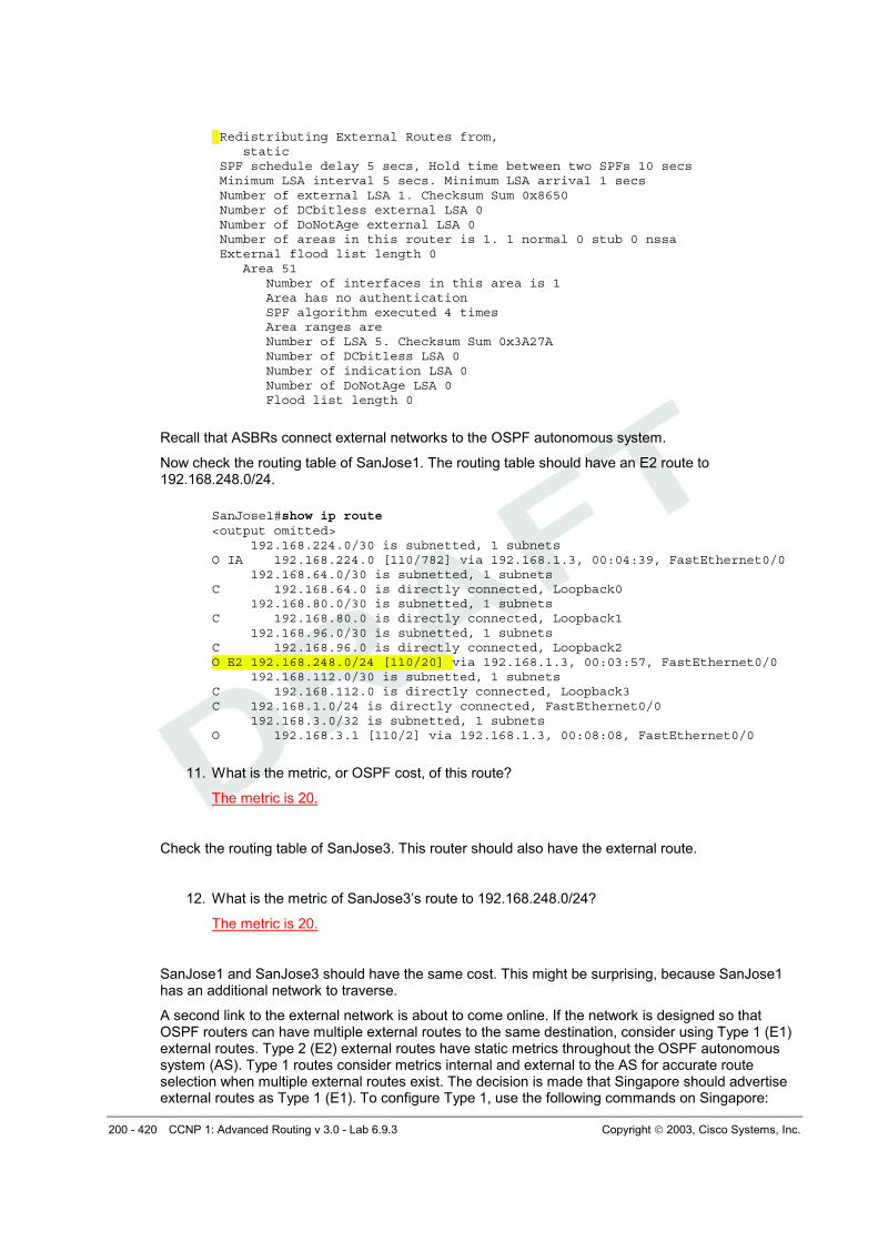
Redistributing External Routes from, static SPF schedule delay 5 secs, Hold time between two SPFs 10 secs Minimum LSA interval 5 secs. Minimum LSA arrival 1 secs Number of external LSA 1. Checksum Sum 0x8650 Number of DCbitless external LSA 0 Number of DoNotAge external LSA 0 Number of areas in this router is 1. 1 normal 0 stub 0 nssa External flood list length 0 Area 51 Number of interfaces in this area is 1 Area has no authentication SPF algorithm executed 4 times Area ranges are Number of LSA 5. Checksum Sum 0x3A27A Number of DCbitless LSA 0 Number of indication LSA 0 Number of DoNotAge LSA 0 Flood list length 0
Recall that ASBRs connect external networks to the OSPF autonomous system.
Now check the routing table of SanJose1. The routing table should have an E2 route to 192.168.248.0/24.
SanJose1#show ip route <output omitted> 192.168.224.0/30 is subnetted, 1 subnets O IA 192.168.224.0 [110/782] via 192.168.1.3, 00:04:39, FastEthernet0/0 192.168.64.0/30 is subnetted, 1 subnets C 192.168.64.0 is directly connected, Loopback0 192.168.80.0/30 is subnetted, 1 subnets C 192.168.80.0 is directly connected, Loopback1 192.168.96.0/30 is subnetted, 1 subnets C 192.168.96.0 is directly connected, Loopback2 O E2 192.168.248.0/24 [110/20] via 192.168.1.3, 00:03:57, FastEthernet0/0 192.168.112.0/30 is subnetted, 1 subnets C 192.168.112.0 is directly connected, Loopback3 C 192.168.1.0/24 is directly connected, FastEthernet0/0 192.168.3.0/32 is subnetted, 1 subnets O 192.168.3.1 [110/2] via 192.168.1.3, 00:08:08, FastEthernet0/0
11. What is the metric, or OSPF cost, of this route?
The metric is 20.
Check the routing table of SanJose3. This router should also have the external route.
12. What is the metric of SanJose3’s route to 192.168.248.0/24?
The metric is 20.
SanJose1 and SanJose3 should have the same cost. This might be surprising, because SanJose1 has an additional network to traverse.
A second link to the external network is about to come online. If the network is designed so that OSPF routers can have multiple external routes to the same destination, consider using Type 1 (E1) external routes. Type 2 (E2) external routes have static metrics throughout the OSPF autonomous system (AS). Type 1 routes consider metrics internal and external to the AS for accurate route selection when multiple external routes exist. The decision is made that Singapore should advertise external routes as Type 1 (E1). To configure Type 1, use the following commands on Singapore:
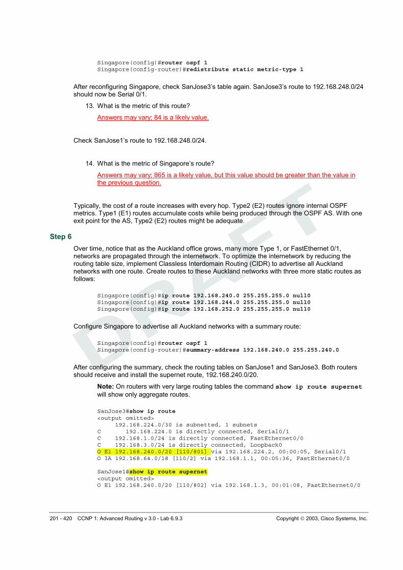
201 - 420 CCNP 1: Advanced Routing v 3.0 - Lab 6.9.3 Copyright 2003, Cisco Systems, Inc.
After reconfiguring Singapore, check SanJose3’s table again. SanJose3’s route to 192.168.248.0/24 should now be Serial 0/1.
13. What is the metric of this route?
Answers may vary; 84 is a likely value.
Check SanJose1’s route to 192.168.248.0/24.
14. What is the metric of Singapore’s route?
Answers may vary; 865 is a likely value, but this value should be greater than the value in the previous question.
Typically, the cost of a route increases with every hop. Type2 (E2) routes ignore internal OSPF metrics. Type1 (E1) routes accumulate costs while being produced through the OSPF AS. With one exit point for the AS, Type2 (E2) routes might be adequate.
Step 6
Over time, notice that as the Auckland office grows, many more Type 1, or FastEthernet 0/1, networks are propagated through the internetwork. To optimize the internetwork by reducing the routing table size, implement Classless Interdomain Routing (CIDR) to advertise all Auckland networks with one route. Create routes to these Auckland networks with three more static routes as follows:
After configuring the summary, check the routing tables on SanJose1 and SanJose3. Both routers should receive and install the supernet route, 192.168.240.0/20.
Note: On routers with very large routing tables the command show ip route supernet
will show only aggregate routes.
SanJose3#show ip route <output omitted> 192.168.224.0/30 is subnetted, 1 subnets C 192.168.224.0 is directly connected, Serial0/1 C 192.168.1.0/24 is directly connected, FastEthernet0/0 C 192.168.3.0/24 is directly connected, Loopback0 O E1 192.168.240.0/20 [110/801] via 192.168.224.2, 00:00:05, Serial0/1 O IA 192.168.64.0/18 [110/2] via 192.168.1.1, 00:05:36, FastEthernet0/0 SanJose1#show ip route supernet <output omitted> O E1 192.168.240.0/20 [110/802] via 192.168.1.3, 00:01:08, FastEthernet0/0
202 - 420 CCNP 1: Advanced Routing v 3.0 - Lab 6.9.3 Copyright 2003, Cisco Systems, Inc.
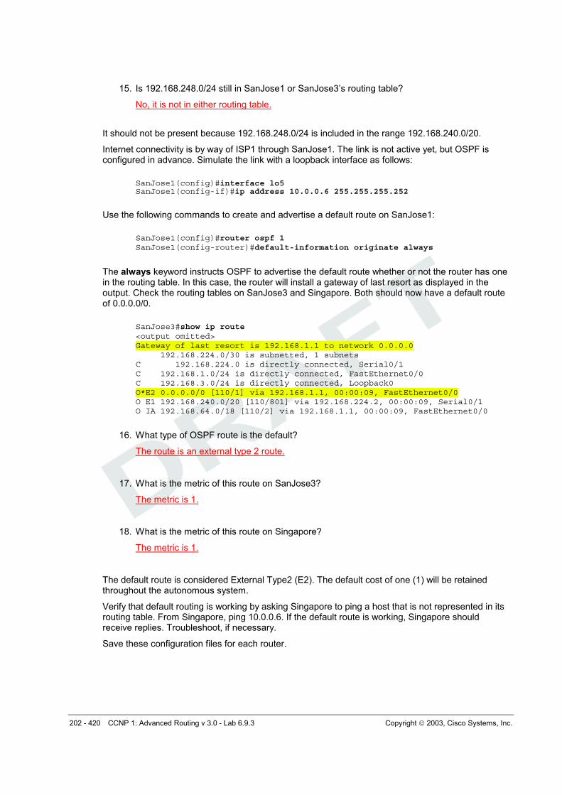
15. Is 192.168.248.0/24 still in SanJose1 or SanJose3’s routing table?
No, it is not in either routing table.
It should not be present because 192.168.248.0/24 is included in the range 192.168.240.0/20.
Internet connectivity is by way of ISP1 through SanJose1. The link is not active yet, but OSPF is configured in advance. Simulate the link with a loopback interface as follows:
The always keyword instructs OSPF to advertise the default route whether or not the router has one in the routing table. In this case, the router will install a gateway of last resort as displayed in the output. Check the routing tables on SanJose3 and Singapore. Both should now have a default route of 0.0.0.0/0.
SanJose3#show ip route <output omitted> Gateway of last resort is 192.168.1.1 to network 0.0.0.0 192.168.224.0/30 is subnetted, 1 subnets C 192.168.224.0 is directly connected, Serial0/1 C 192.168.1.0/24 is directly connected, FastEthernet0/0 C 192.168.3.0/24 is directly connected, Loopback0 O*E2 0.0.0.0/0 [110/1] via 192.168.1.1, 00:00:09, FastEthernet0/0 O E1 192.168.240.0/20 [110/801] via 192.168.224.2, 00:00:09, Serial0/1 O IA 192.168.64.0/18 [110/2] via 192.168.1.1, 00:00:09, FastEthernet0/0
16. What type of OSPF route is the default?
The route is an external type 2 route.
17. What is the metric of this route on SanJose3?
The metric is 1.
18. What is the metric of this route on Singapore?
The metric is 1.
The default route is considered External Type2 (E2). The default cost of one (1) will be retained throughout the autonomous system.
Verify that default routing is working by asking Singapore to ping a host that is not represented in its routing table. From Singapore, ping 10.0.0.6. If the default route is working, Singapore should receive replies. Troubleshoot, if necessary.
Save these configuration files for each router.
203 - 420 CCNP 1: Advanced Routing v 3.0 - Lab 6.9.3 Copyright 2003, Cisco Systems, Inc.
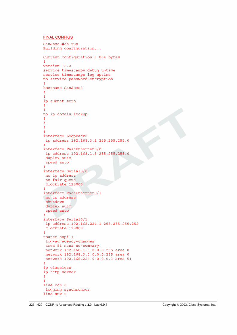
FINAL CONFIGS
SanJose3#sh run Building configuration... Current configuration : 839 bytes ! version 12.2 service timestamps debug uptime service timestamps log uptime no service password-encryption ! hostname SanJose3 ! ! ip subnet-zero ! ! no ip domain-lookup ! ! ! ! interface Loopback0 ip address 192.168.3.1 255.255.255.0 ! interface FastEthernet0/0 ip address 192.168.1.3 255.255.255.0 duplex auto speed auto ! interface Serial0/0 no ip address no fair-queue clockrate 128000 ! interface FastEthernet0/1 no ip address shutdown duplex auto speed auto ! interface Serial0/1 ip address 192.168.224.1 255.255.255.252 clockrate 128000 ! router ospf 1 log-adjacency-changes network 192.168.1.0 0.0.0.255 area 0 network 192.168.3.0 0.0.0.255 area 0 network 192.168.224.0 0.0.0.3 area 51 ! ip classless ip http server ! ! line con 0 logging synchronous line aux 0 line vty 0 4
204 - 420 CCNP 1: Advanced Routing v 3.0 - Lab 6.9.3 Copyright 2003, Cisco Systems, Inc.
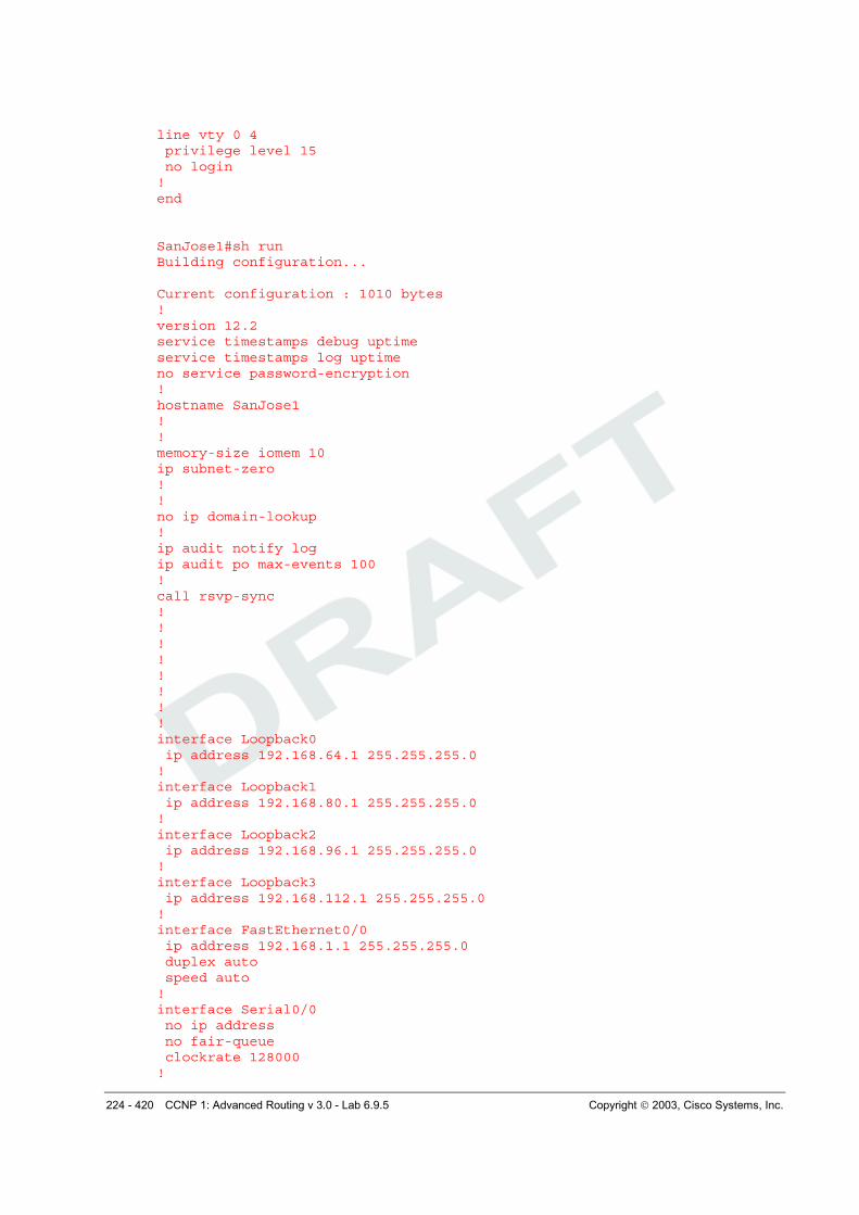
privilege level 15 no login ! end SanJose1#sh run Building configuration... Current configuration : 1175 bytes ! version 12.2 service timestamps debug uptime service timestamps log uptime no service password-encryption ! hostname SanJose1 ! ! memory-size iomem 10 ip subnet-zero ! ! no ip domain-lookup ! ip audit notify log ip audit po max-events 100 ! call rsvp-sync ! ! ! ! ! ! ! ! interface Loopback0 ip address 192.168.64.1 255.255.255.0 ! interface Loopback1 ip address 192.168.80.1 255.255.255.0 ! interface Loopback2 ip address 192.168.96.1 255.255.255.0 ! interface Loopback3 ip address 192.168.112.1 255.255.255.0 ! interface Loopback5 ip address 10.0.0.6 255.255.255.252 ! interface FastEthernet0/0 ip address 192.168.1.1 255.255.255.0 duplex auto speed auto ! interface Serial0/0 no ip address no fair-queue
205 - 420 CCNP 1: Advanced Routing v 3.0 - Lab 6.9.3 Copyright 2003, Cisco Systems, Inc.
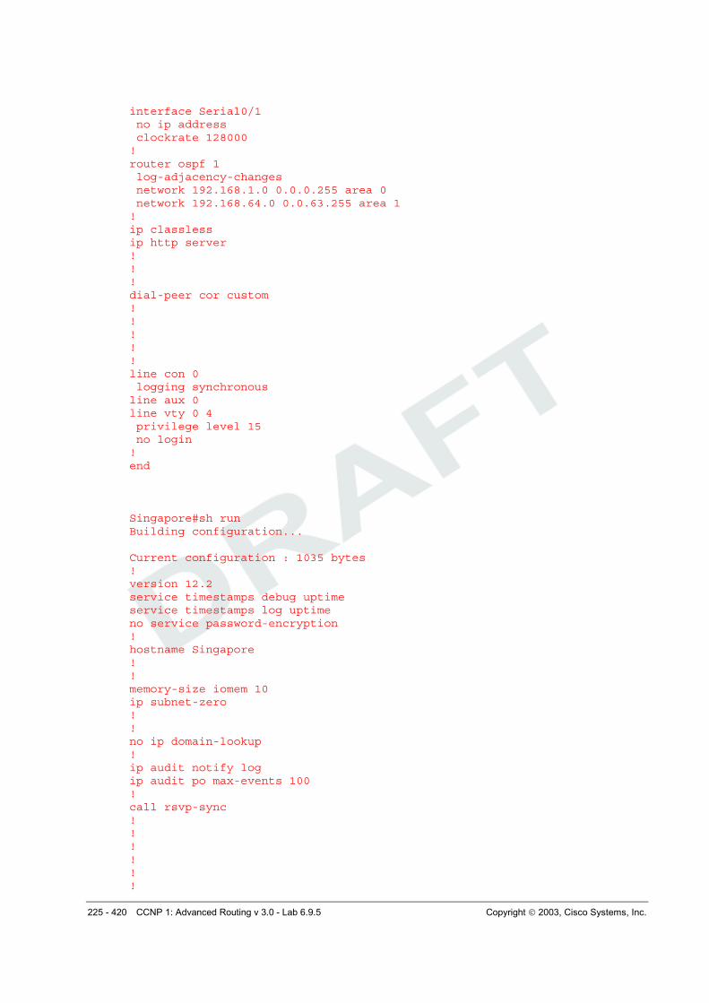
clockrate 128000 ! interface Serial0/1 ip address 192.168.224.1 255.255.255.252 clockrate 128000 ! router ospf 1 log-adjacency-changes area 1 range 192.168.64.0 255.255.192.0 network 192.168.1.0 0.0.0.255 area 0 network 192.168.64.0 0.0.63.255 area 1 default-information originate always ! ip classless ip http server ! ! ! dial-peer cor custom ! ! ! ! ! line con 0 logging synchronous line aux 0 line vty 0 4 privilege level 15 no login ! end Singapore#sh run Building configuration... Current configuration : 960 bytes ! version 12.2 service timestamps debug uptime service timestamps log uptime no service password-encryption ! hostname Singapore ! ! memory-size iomem 10 ip subnet-zero ! ! no ip domain-lookup ! ip audit notify log ip audit po max-events 100 ! call rsvp-sync ! ! !
206 - 420 CCNP 1: Advanced Routing v 3.0 - Lab 6.9.3 Copyright 2003, Cisco Systems, Inc.
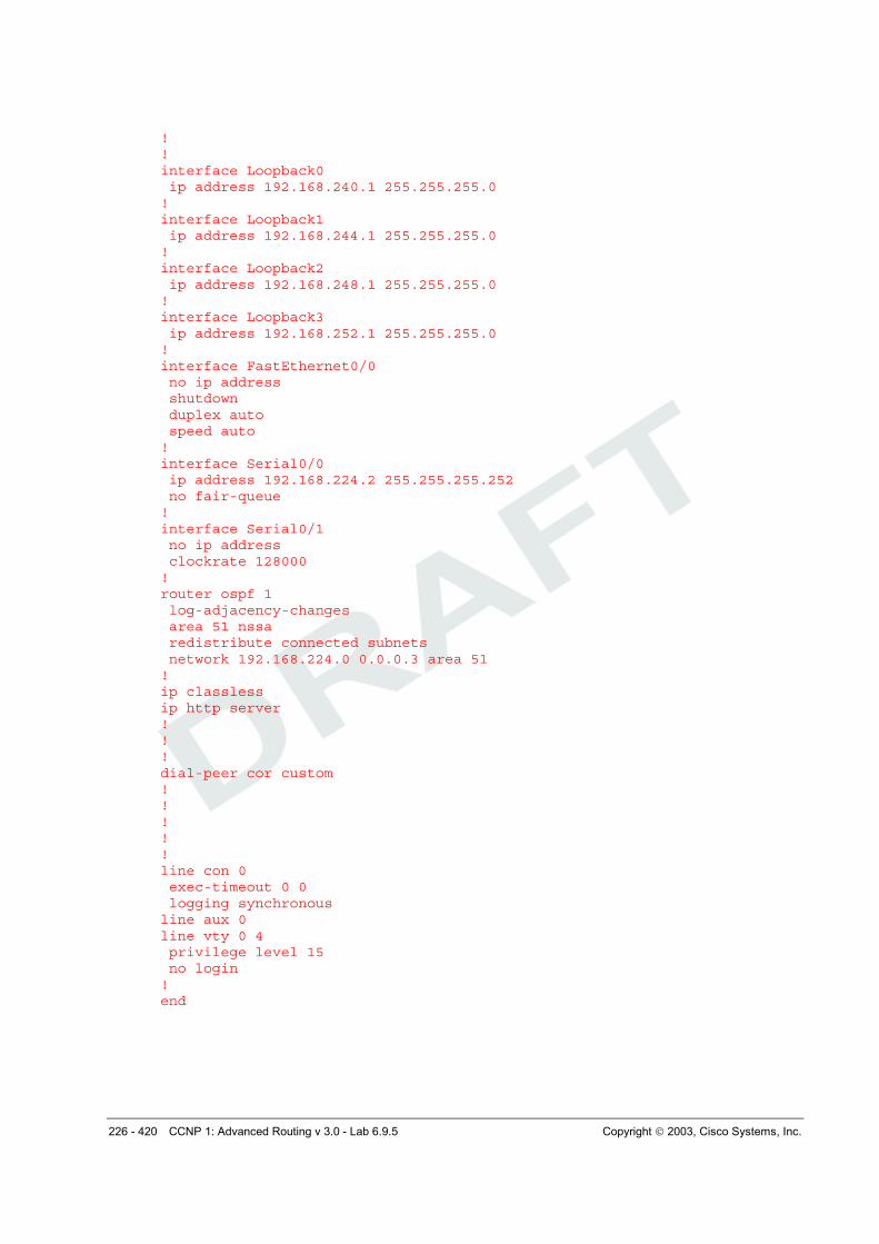
! ! ! ! ! interface FastEthernet0/0 no ip address shutdown duplex auto speed auto ! interface Serial0/0 ip address 192.168.224.2 255.255.255.252 ! interface Serial0/1 no ip address clockrate 128000 ! router ospf 1 log-adjacency-changes summary-address 192.168.240.0 255.255.240.0 redistribute static metric-type 1 network 192.168.224.0 0.0.0.3 area 51 ! ip classless ip route 192.168.240.0 255.255.255.0 Null0 ip route 192.168.244.0 255.255.255.0 Null0 ip route 192.168.248.0 255.255.255.0 Null0 ip route 192.168.252.0 255.255.255.0 Null0 ip http server ! ! ! dial-peer cor custom ! ! ! ! ! line con 0 logging synchronous line aux 0 line vty 0 4 privilege level 15 no login ! end
207 - 420 CCNP 1: Advanced Routing v 3.0 - Lab 6.9.4 Copyright 2003, Cisco Systems, Inc.
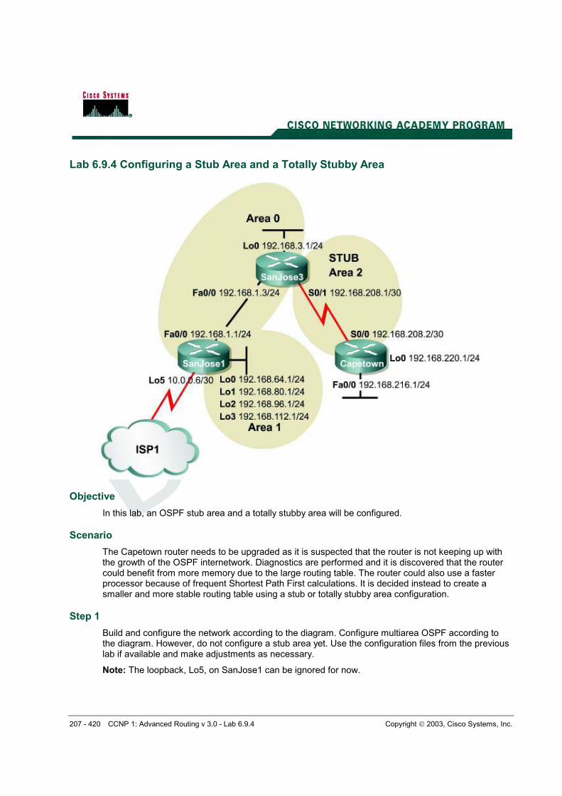
Lab 6.9.4 Configuring a Stub Area and a Totally Stubby Area
Objective
In this lab, an OSPF stub area and a totally stubby area will be configured.
Scenario
The Capetown router needs to be upgraded as it is suspected that the router is not keeping up with the growth of the OSPF internetwork. Diagnostics are performed and it is discovered that the router could benefit from more memory due to the large routing table. The router could also use a faster processor because of frequent Shortest Path First calculations. It is decided instead to create a smaller and more stable routing table using a stub or totally stubby area configuration.
Step 1
Build and configure the network according to the diagram. Configure multiarea OSPF according to the diagram. However, do not configure a stub area yet. Use the configuration files from the previous lab if available and make adjustments as necessary.
Note: The loopback, Lo5, on SanJose1 can be ignored for now.
208 - 420 CCNP 1: Advanced Routing v 3.0 - Lab 6.9.4 Copyright 2003, Cisco Systems, Inc.
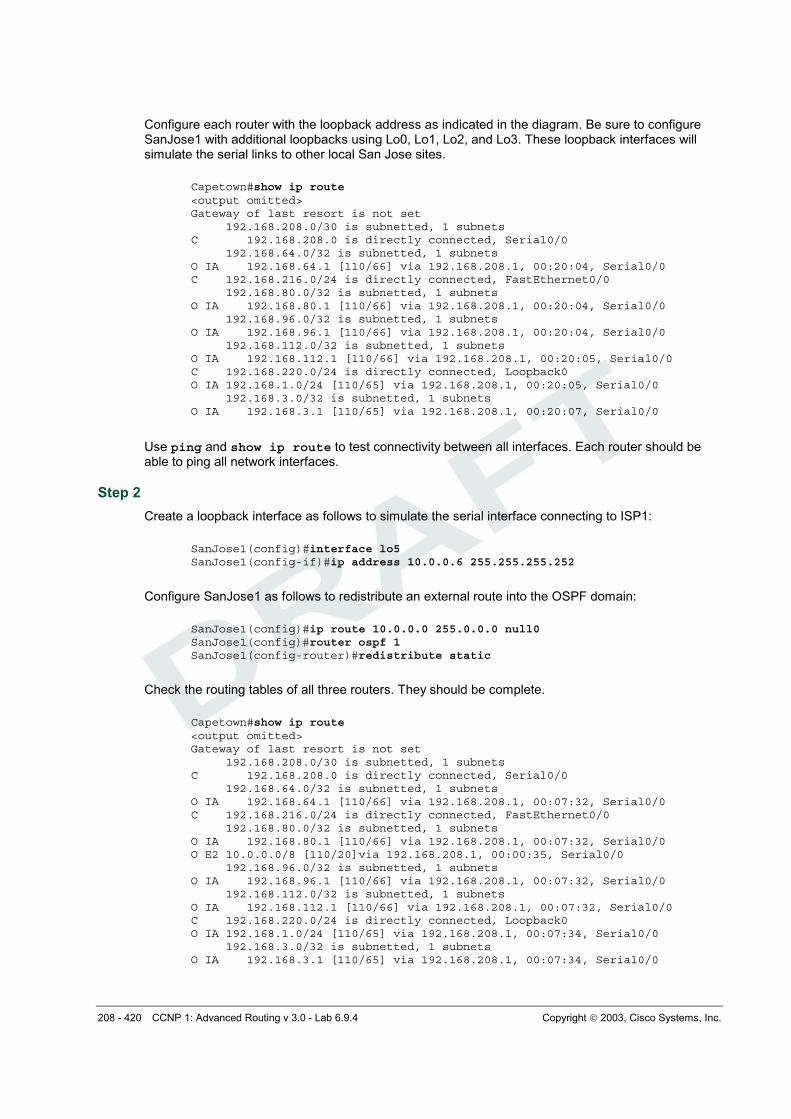
Configure each router with the loopback address as indicated in the diagram. Be sure to configure SanJose1 with additional loopbacks using Lo0, Lo1, Lo2, and Lo3. These loopback interfaces will simulate the serial links to other local San Jose sites.
Capetown#show ip route <output omitted> Gateway of last resort is not set 192.168.208.0/30 is subnetted, 1 subnets C 192.168.208.0 is directly connected, Serial0/0 192.168.64.0/32 is subnetted, 1 subnets O IA 192.168.64.1 [110/66] via 192.168.208.1, 00:20:04, Serial0/0 C 192.168.216.0/24 is directly connected, FastEthernet0/0 192.168.80.0/32 is subnetted, 1 subnets O IA 192.168.80.1 [110/66] via 192.168.208.1, 00:20:04, Serial0/0 192.168.96.0/32 is subnetted, 1 subnets O IA 192.168.96.1 [110/66] via 192.168.208.1, 00:20:04, Serial0/0 192.168.112.0/32 is subnetted, 1 subnets O IA 192.168.112.1 [110/66] via 192.168.208.1, 00:20:05, Serial0/0 C 192.168.220.0/24 is directly connected, Loopback0 O IA 192.168.1.0/24 [110/65] via 192.168.208.1, 00:20:05, Serial0/0 192.168.3.0/32 is subnetted, 1 subnets O IA 192.168.3.1 [110/65] via 192.168.208.1, 00:20:07, Serial0/0
Use ping and show ip route to test connectivity between all interfaces. Each router should be able to ping all network interfaces.
Step 2
Create a loopback interface as follows to simulate the serial interface connecting to ISP1:
Check the routing tables of all three routers. They should be complete.
Capetown#show ip route <output omitted> Gateway of last resort is not set 192.168.208.0/30 is subnetted, 1 subnets C 192.168.208.0 is directly connected, Serial0/0 192.168.64.0/32 is subnetted, 1 subnets O IA 192.168.64.1 [110/66] via 192.168.208.1, 00:07:32, Serial0/0 C 192.168.216.0/24 is directly connected, FastEthernet0/0 192.168.80.0/32 is subnetted, 1 subnets O IA 192.168.80.1 [110/66] via 192.168.208.1, 00:07:32, Serial0/0 O E2 10.0.0.0/8 [110/20]via 192.168.208.1, 00:00:35, Serial0/0 192.168.96.0/32 is subnetted, 1 subnets O IA 192.168.96.1 [110/66] via 192.168.208.1, 00:07:32, Serial0/0 192.168.112.0/32 is subnetted, 1 subnets O IA 192.168.112.1 [110/66] via 192.168.208.1, 00:07:32, Serial0/0 C 192.168.220.0/24 is directly connected, Loopback0 O IA 192.168.1.0/24 [110/65] via 192.168.208.1, 00:07:34, Serial0/0 192.168.3.0/32 is subnetted, 1 subnets O IA 192.168.3.1 [110/65] via 192.168.208.1, 00:07:34, Serial0/0
209 - 420 CCNP 1: Advanced Routing v 3.0 - Lab 6.9.4 Copyright 2003, Cisco Systems, Inc.
SanJose3 and Capetown should also have a Type 2 external route to 10.0.0.0/8. They will not have a specific route to the loopback network, 10.0.0.4/30. That network has not clearly been advertised by any means.
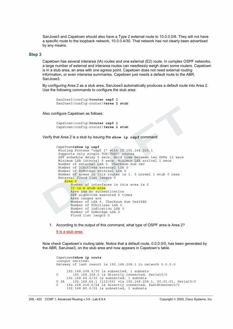
Step 3
Capetown has several interarea (IA) routes and one external (E2) route. In complex OSPF networks, a large number of external and interarea routes can needlessly weigh down some routers. Capetown is in a stub area, an area with one egress point. Capetown does not need external routing information, or even interarea summaries. Capetown just needs a default route to the ABR, SanJose3.
By configuring Area 2 as a stub area, SanJose3 automatically produces a default route into Area 2. Use the following commands to configure the stub area:
Verify that Area 2 is a stub by issuing the show ip ospf command:
CapeTown#show ip ospf Routing Process "ospf 1" with ID 192.168.220.1 Supports only single TOS(TOS0) routes SPF schedule delay 5 secs, Hold time between two SPFs 10 secs Minimum LSA interval 5 secs. Minimum LSA arrival 1 secs Number of external LSA 0. Checksum Sum 0x0 Number of DCbitless external LSA 0 Number of DoNotAge external LSA 0 Number of areas in this router is 1. 0 normal 1 stub 0 nssa External flood list length 0 Area 2 Number of interfaces in this area is 2 It is a stub area Area has no authentication SPF algorithm executed 6 times Area ranges are Number of LSA 9. Checksum Sum 0x428E6 Number of DCbitless LSA 0 Number of indication LSA 0 Number of DoNotAge LSA 0 Flood list length 0
1. According to the output of this command, what type of OSPF area is Area 2?
It is a stub area.
Now check Capetown’s routing table. Notice that a default route, 0.0.0.0/0, has been generated by the ABR, SanJose3, on the stub area and now appears in Capetown’s table.
Capetown#show ip route <output omitted> Gateway of last resort is 192.168.208.1 to network 0.0.0.0 192.168.208.0/30 is subnetted, 1 subnets C 192.168.208.0 is directly connected, Serial0/0 192.168.64.0/32 is subnetted, 1 subnets O IA 192.168.64.1 [110/66] via 192.168.208.1, 00:01:01, Serial0/0 C 192.168.216.0/24 is directly connected, FastEthernet0/0 192.168.80.0/32 is subnetted, 1 subnets
210 - 420 CCNP 1: Advanced Routing v 3.0 - Lab 6.9.4 Copyright 2003, Cisco Systems, Inc.
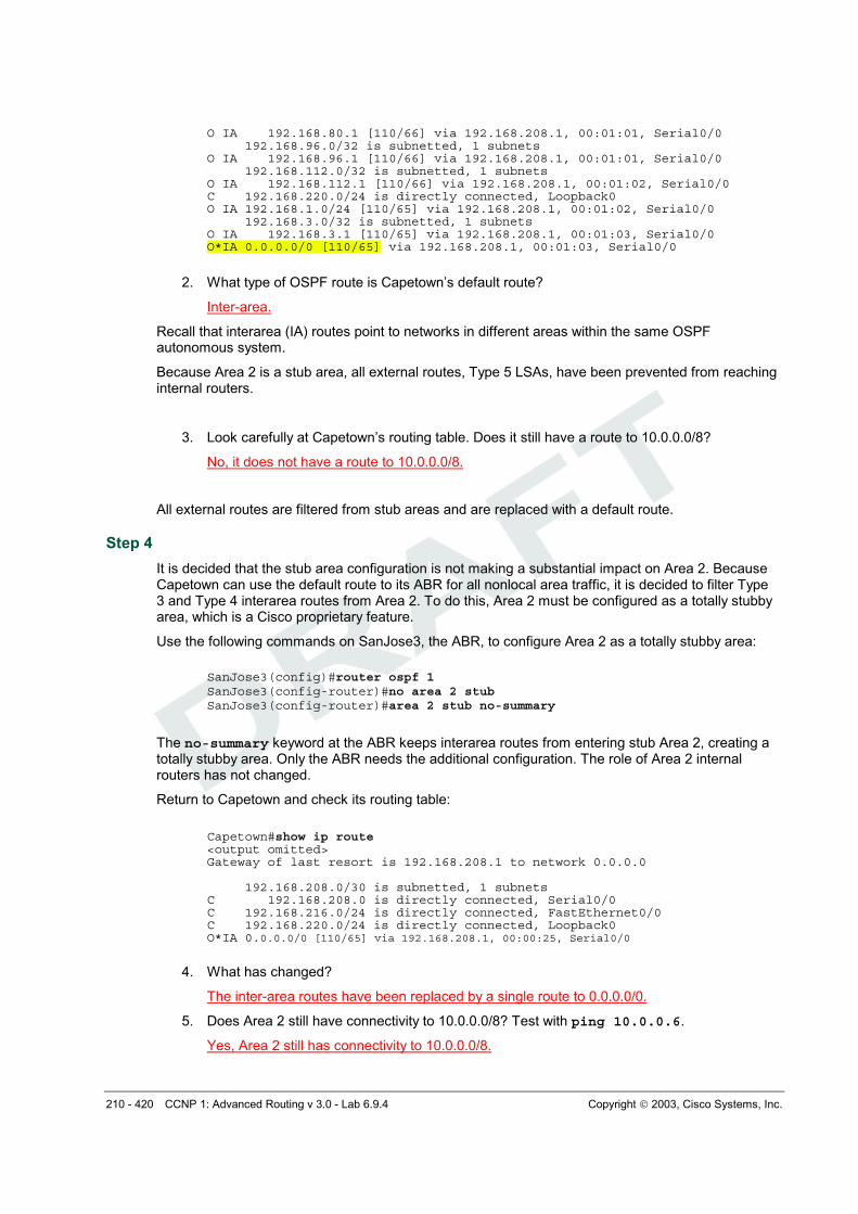
O IA 192.168.80.1 [110/66] via 192.168.208.1, 00:01:01, Serial0/0 192.168.96.0/32 is subnetted, 1 subnets O IA 192.168.96.1 [110/66] via 192.168.208.1, 00:01:01, Serial0/0 192.168.112.0/32 is subnetted, 1 subnets O IA 192.168.112.1 [110/66] via 192.168.208.1, 00:01:02, Serial0/0 C 192.168.220.0/24 is directly connected, Loopback0 O IA 192.168.1.0/24 [110/65] via 192.168.208.1, 00:01:02, Serial0/0 192.168.3.0/32 is subnetted, 1 subnets O IA 192.168.3.1 [110/65] via 192.168.208.1, 00:01:03, Serial0/0 O*IA 0.0.0.0/0 [110/65] via 192.168.208.1, 00:01:03, Serial0/0
2. What type of OSPF route is Capetown’s default route?
Inter-area.
Recall that interarea (IA) routes point to networks in different areas within the same OSPF autonomous system.
Because Area 2 is a stub area, all external routes, Type 5 LSAs, have been prevented from reaching internal routers.
3. Look carefully at Capetown’s routing table. Does it still have a route to 10.0.0.0/8?
No, it does not have a route to 10.0.0.0/8.
All external routes are filtered from stub areas and are replaced with a default route.
Step 4
It is decided that the stub area configuration is not making a substantial impact on Area 2. Because Capetown can use the default route to its ABR for all nonlocal area traffic, it is decided to filter Type 3 and Type 4 interarea routes from Area 2. To do this, Area 2 must be configured as a totally stubby area, which is a Cisco proprietary feature.
Use the following commands on SanJose3, the ABR, to configure Area 2 as a totally stubby area:
The no-summary keyword at the ABR keeps interarea routes from entering stub Area 2, creating a totally stubby area. Only the ABR needs the additional configuration. The role of Area 2 internal routers has not changed.
Return to Capetown and check its routing table:
Capetown#show ip route <output omitted> Gateway of last resort is 192.168.208.1 to network 0.0.0.0 192.168.208.0/30 is subnetted, 1 subnets C 192.168.208.0 is directly connected, Serial0/0 C 192.168.216.0/24 is directly connected, FastEthernet0/0 C 192.168.220.0/24 is directly connected, Loopback0 O*IA 0.0.0.0/0 [110/65] via 192.168.208.1, 00:00:25, Serial0/0
4. What has changed?
The inter-area routes have been replaced by a single route to 0.0.0.0/0.
5. Does Area 2 still have connectivity to 10.0.0.0/8? Test with ping 10.0.0.6.
Yes, Area 2 still has connectivity to 10.0.0.0/8.
211 - 420 CCNP 1: Advanced Routing v 3.0 - Lab 6.9.4 Copyright 2003, Cisco Systems, Inc.
Interarea routes have also been replaced by a default route.
Capetown should get a positive response by forwarding ICMP requests to SanJose3 using the default route 0.0.0.0/0. SanJose3 has a default route to network 10.0.0.0/8, and SanJose1 has a directly connected route to 10.0.0.4/30 with the loopback interface 10.0.0.6/30.
212 - 420 CCNP 1: Advanced Routing v 3.0 - Lab 6.9.4 Copyright 2003, Cisco Systems, Inc.
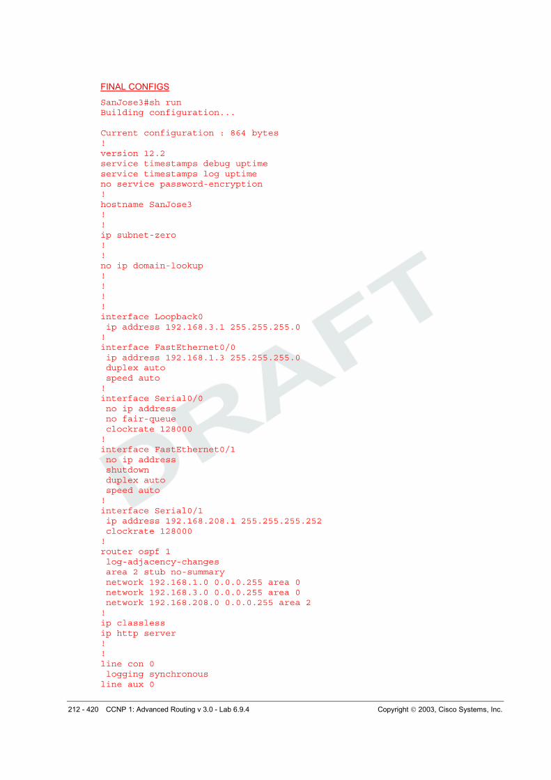
FINAL CONFIGS
SanJose3#sh run Building configuration... Current configuration : 864 bytes ! version 12.2 service timestamps debug uptime service timestamps log uptime no service password-encryption ! hostname SanJose3 ! ! ip subnet-zero ! ! no ip domain-lookup ! ! ! ! interface Loopback0 ip address 192.168.3.1 255.255.255.0 ! interface FastEthernet0/0 ip address 192.168.1.3 255.255.255.0 duplex auto speed auto ! interface Serial0/0 no ip address no fair-queue clockrate 128000 ! interface FastEthernet0/1 no ip address shutdown duplex auto speed auto ! interface Serial0/1 ip address 192.168.208.1 255.255.255.252 clockrate 128000 ! router ospf 1 log-adjacency-changes area 2 stub no-summary network 192.168.1.0 0.0.0.255 area 0 network 192.168.3.0 0.0.0.255 area 0 network 192.168.208.0 0.0.0.255 area 2 ! ip classless ip http server ! ! line con 0 logging synchronous line aux 0
213 - 420 CCNP 1: Advanced Routing v 3.0 - Lab 6.9.4 Copyright 2003, Cisco Systems, Inc.
line vty 0 4 privilege level 15 no login ! end SanJose1#sh run Building configuration... Current configuration : 1124 bytes ! version 12.2 service timestamps debug uptime service timestamps log uptime no service password-encryption ! hostname SanJose1 ! ! memory-size iomem 10 ip subnet-zero ! ! no ip domain-lookup ! ip audit notify log ip audit po max-events 100 ! call rsvp-sync ! ! ! ! ! ! ! ! interface Loopback0 ip address 192.168.64.1 255.255.255.0 ! interface Loopback1 ip address 192.168.80.1 255.255.255.0 ! interface Loopback2 ip address 192.168.96.1 255.255.255.0 ! interface Loopback3 ip address 192.168.112.1 255.255.255.0 ! interface Loopback5 ip address 10.0.0.6 255.255.255.252 ! interface FastEthernet0/0 ip address 192.168.1.1 255.255.255.0 duplex auto speed auto ! interface Serial0/0 no ip address
214 - 420 CCNP 1: Advanced Routing v 3.0 - Lab 6.9.4 Copyright 2003, Cisco Systems, Inc.
no fair-queue clockrate 128000 ! interface Serial0/1 no ip address clockrate 128000 ! router ospf 1 log-adjacency-changes redistribute static network 192.168.1.0 0.0.0.255 area 0 network 192.168.64.0 0.0.63.255 area 1 ! ip classless ip route 10.0.0.0 255.0.0.0 Null0 ip http server ! ! ! dial-peer cor custom ! ! ! ! ! line con 0 logging synchronous line aux 0 line vty 0 4 privilege level 15 no login ! end Capetown#sh run Building configuration... Current configuration : 890 bytes ! version 12.2 service timestamps debug uptime service timestamps log uptime no service password-encryption ! hostname Capetown ! ! memory-size iomem 10 ip subnet-zero ! ! no ip domain-lookup ! ip audit notify log ip audit po max-events 100 ! call rsvp-sync !
215 - 420 CCNP 1: Advanced Routing v 3.0 - Lab 6.9.4 Copyright 2003, Cisco Systems, Inc.
! ! ! ! ! ! ! interface Loopback0 ip address 192.168.220.1 255.255.255.0 ! interface FastEthernet0/0 ip address 192.168.216.1 255.255.255.0 no keepalive duplex auto speed auto ! interface Serial0/0 ip address 192.168.208.2 255.255.255.252 ! interface Serial0/1 no ip address clockrate 128000 ! router ospf 1 log-adjacency-changes area 2 stub network 192.168.208.0 0.0.0.3 area 2 network 192.168.216.0 0.0.0.255 area 2 network 192.168.220.0 0.0.0.255 area 2 ! ip classless ip http server ! ! ! dial-peer cor custom ! ! ! ! ! line con 0 logging synchronous line aux 0 line vty 0 4 privilege level 15 no login ! end
216 - 420 CCNP 1: Advanced Routing v 3.0 - Lab 6.9.5 Copyright 2003, Cisco Systems, Inc.
Lab 6.9.5 Configuring an NSSA
Objective
In this lab, the student will configure an OSPF NSSA in order to import external routing information while retaining the benefits of a stub area.
Scenario
The implementation of a totally stubby area in Area 2 was very successful. Now implement it in Area 51 for more efficient routing and greater route stability. A stub or totally stubby area will not work, because the Singapore router in Area 51 has the added responsibility of redistributing external routes from Auckland using Type 5 LSAs. To meet every need, it is decided to configure Area 51 as an a Not So Stubby Area (NSSA).
Step 1
Build and configure the network according to the diagram. Also configure multiarea OSPF according to the diagram. However, do not configure NSSA yet. Use the configuration files from the previous lab if available and make adjustments as necessary. In this case it is easiest to just remove and reapply the OSPF process. Reboot after reconfiguring OSPF if there are any problems.
217 - 420 CCNP 1: Advanced Routing v 3.0 - Lab 6.9.5 Copyright 2003, Cisco Systems, Inc.
Note: This lab requires the use of subnet 0.
Configure each router with the loopback address indicated in the diagram. Be sure to configure SanJose1 and Singapore with additional loopbacks (Lo0, Lo1, Lo2, Lo3). On SanJose1, these loopback interfaces simulate the serial links to local San Jose sites: Westasman, Baypointe, Vista, and Eastasman. On Singapore, the loopbacks simulate Auckland networks.
Use ping and show ip route to test connectivity between all interfaces. Each router should be able to ping all network interfaces as the following shows:
SanJose3#show ip route <output omitted> 192.168.224.0/30 is subnetted, 1 subnets C 192.168.224.0 is directly connected, Serial0/0 192.168.64.0/32 is subnetted, 1 subnets O IA 192.168.64.1 [110/2] via 192.168.1.1, 00:03:49, FastEthernet0/0 192.168.80.0/32 is subnetted, 1 subnets O IA 192.168.80.1 [110/2] via 192.168.1.1, 00:03:49, FastEthernet0/0 192.168.96.0/32 is subnetted, 1 subnets O IA 192.168.96.1 [110/2] via 192.168.1.1, 00:03:49, FastEthernet0/0 192.168.112.0/32 is subnetted, 1 subnets O IA 192.168.112.1 [110/2] via 192.168.1.1, 00:03:49, FastEthernet0/0 C 192.168.1.0/24 is directly connected, FastEthernet0/0 C 192.168.3.0/24 is directly connected, Loopback0
Step 2
Configure Singapore as follows to redistribute connected routes into the OSPF domain:
This command advertises Singapore’s loopbacks as external networks. Check the routing tables of all three routers. They should be complete. SanJose1 and SanJose3 should also have Type 2 external routes to the Auckland networks as the following shows:
SanJose1#show ip route <output omitted> 192.168.224.0/30 is subnetted, 1 subnets O IA 192.168.224.0 [110/782] via 192.168.1.3, 00:11:16, FastEthernet0/0 192.168.240.0/30 is subnetted, 1 subnets O E2 192.168.240.0 [110/20] via 192.168.1.3, 00:04:54, FastEthernet0/0 O E2 192.168.244.0/24 [110/20] via 192.168.1.3, 00:09:34, FastEthernet0/0 192.168.64.0/30 is subnetted, 1 subnets C 192.168.64.0 is directly connected, Loopback0 192.168.80.0/30 is subnetted, 1 subnets C 192.168.80.0 is directly connected, Loopback1 192.168.96.0/30 is subnetted, 1 subnets C 192.168.96.0 is directly connected, Loopback2 O E2 192.168.248.0/24 [110/20] via 192.168.1.3, 00:09:35, FastEthernet0/0 192.168.112.0/30 is subnetted, 1 subnets C 192.168.112.0 is directly connected, Loopback3 C 192.168.1.0/24 is directly connected, FastEthernet0/0 O E2 192.168.252.0/24 [110/20] via 192.168.1.3, 00:09:38, FastEthernet0/0 192.168.3.0/32 is subnetted, 1 subnets
• 192.168.3.1 [110/2] via 192.168.1.3, 00:11:19, FastEthernet0/0
•
218 - 420 CCNP 1: Advanced Routing v 3.0 - Lab 6.9.5 Copyright 2003, Cisco Systems, Inc.
Step 3
The following shows that Singapore has several interarea (IA) routes.
Singapore#show ip route <output omitted> Gateway of last resort is not set 192.168.224.0/30 is subnetted, 1 subnets C 192.168.224.0 is directly connected, Serial0/0 192.168.240.0/30 is subnetted, 1 subnets C 192.168.240.0 is directly connected, Loopback0 C 192.168.244.0/24 is directly connected, Loopback1 192.168.64.0/32 is subnetted, 1 subnets O IA 192.168.64.1 [110/66] via 192.168.224.1, 00:00:48, Serial0/0 192.168.80.0/32 is subnetted, 1 subnets O IA 192.168.80.1 [110/66] via 192.168.224.1, 00:00:48, Serial0/0 192.168.96.0/32 is subnetted, 1 subnets O IA 192.168.96.1 [110/66] via 192.168.224.1, 00:00:49, Serial0/0 C 192.168.248.0/24 is directly connected, Loopback2 192.168.112.0/32 is subnetted, 1 subnets O IA 192.168.112.1 [110/66] via 192.168.224.1, 00:00:49, Serial0/0 O IA 192.168.1.0/24 [110/65] via 192.168.224.1, 00:00:49, Serial0/0 C 192.168.252.0/24 is directly connected, Loopback3 192.168.3.0/32 is subnetted, 1 subnets O IA 192.168.3.1 [110/65] via 192.168.224.1, 00:00:49, Serial0/0
In Lab 6.9.4, Capetown’s table was minimized by configuring Area 2 as a stub. Attempt to repeat this configuration with the following commands on Singapore:
1. What does the router output when this command is entered?
“OSPF: Stub command is invalid when it is ASBR”.
Because Singapore imports routes that are external to OSPF, it is considered an ASBR. ASBRs cannot be members of a stub area. Stub areas do not permit Type 5 LSAs. Issue the show ip
ospf database command on Singapore. Note that OSPF Router IDs are used as references in
managing the link-state database. The OSPF process may have to be removed and reinstalled or possibly the routers will need to be rebooted to get the desired result:
Singapore#show ip ospf database OSPF Router with ID (192.168.252.1) (Process ID 1) Router Link States (Area 51) Link ID ADV Router Age Seq# Checksum Link count 192.168.3.1 192.168.3.1 817 0x80000004 0xF239 2 192.168.252.1 192.168.252.1 1307 0x80000002 0xB918 2 Summary Net Link States (Area 51) Link ID ADV Router Age Seq# Checksum 192.168.1.0 192.168.3.1 1262 0x80000003 0xABB6 192.168.3.1 192.168.3.1 1308 0x80000001 0x8FD1 192.168.64.1 192.168.3.1 1258 0x80000001 0xF72B 192.168.80.1 192.168.3.1 1258 0x80000001 0x47CB 192.168.96.1 192.168.3.1 1258 0x80000001 0x966C 192.168.112.1 192.168.3.1 1258 0x80000001 0xE50D Type-5 AS External Link States Link ID ADV Router Age Seq# Checksum Tag 192.168.224.0 192.168.252.1 429 0x80000001 0x7D74 0
219 - 420 CCNP 1: Advanced Routing v 3.0 - Lab 6.9.5 Copyright 2003, Cisco Systems, Inc.
Now use the show ip ospf database command on Singapore. Because stub areas do not support Type 5 LSAs, external routes are redistributed and are advertised as Type 7 LSAs. The output of this command should verify that Type 5 LSAs have been replaced by Type 7 LSAs.
Singapore#show ip ospf database OSPF Router with ID (192.168.252.1) (Process ID 1) Router Link States (Area 51) Link ID ADV Router Age Seq# Checksum Link count 192.168.3.1 192.168.3.1 10 0x80000006 0x9A87 2 192.168.252.1 192.168.252.1 10 0x80000004 0x5B6E 2 Summary Net Link States (Area 51) Link ID ADV Router Age Seq# Checksum 192.168.1.0 192.168.3.1 137 0x80000004 0x4F0C 192.168.3.1 192.168.3.1 137 0x80000002 0x3327 192.168.64.1 192.168.3.1 138 0x80000002 0x9B80 192.168.80.1 192.168.3.1 138 0x80000002 0xEA21 192.168.96.1 192.168.3.1 138 0x80000002 0x3AC1 192.168.112.1 192.168.3.1 138 0x80000002 0x8962 Type-7 AS External Link States (Area 51) Link ID ADV Router Age Seq# Checksum Tag 192.168.224.0 192.168.252.1 19 0x80000001 0xA0FA 0 192.168.240.0 192.168.252.1 20 0x80000001 0xEF9B 0 192.168.244.0 192.168.252.1 21 0x80000001 0xD5AE 0 192.168.248.0 192.168.252.1 21 0x80000001 0xA9D6 0 192.168.252.0 192.168.252.1 21 0x80000001 0x7DFE 0
Enter the show ip route command on Singapore. Below you will see how the routing table
changes with the no-summary option in OSPF.
NSSA routers receive updates from the ABR the same way stub area routers do. Singapore’s routing table should look similar to how Capetown’s table did when it was in a stub area. See Lab 6.8.2. SanJose3 continues to flood Area 51 with summary link, Type 3 and Type 4, LSAs. Because the goal is to reduce the burden on Area 51 routers, reconfigure SanJose3 as follows to filter interarea summary LSAs:
220 - 420 CCNP 1: Advanced Routing v 3.0 - Lab 6.9.5 Copyright 2003, Cisco Systems, Inc.
Again, check Singapore’s routing table:
Singapore#show ip route <output omitted> Gateway of last resort is 192.168.224.1 to network 0.0.0.0 192.168.224.0/30 is subnetted, 1 subnets C 192.168.224.0 is directly connected, Serial0/0 192.168.240.0/30 is subnetted, 1 subnets C 192.168.240.0 is directly connected, Loopback0 C 192.168.244.0/24 is directly connected, Loopback1 C 192.168.248.0/24 is directly connected, Loopback2 C 192.168.252.0/24 is directly connected, Loopback3 O*IA 0.0.0.0/0 [110/65] via 192.168.224.1, 00:00:04, Serial0/0
3. What has changed?
The inter-area routes have been replaced by a single route to 0.0.0.0/0.
All interarea (IA) routes are replaced with the 0.0.0.0/0 default route. Area 51 is now acting like Area 2 when it was configured as totally stubby. See Lab 6.8.2. The primary difference is that an NSSA can redistribute external routes.
NSSAs allow the OSPF link state databases to be minimized within an area, yet still import external routes as Type 7 LSAs. The NSSA ABR, in this case SanJose3, must convert these Type 7s into Type 5s, which will overflow into Area 0. On SanJose3, issue the show ip ospf database command as follows:
SanJose3#show ip ospf database OSPF Router with ID (192.168.3.1) (Process ID 1) Router Link States (Area 0) Link ID ADV Router Age Seq# Checksum Link count 192.168.3.1 192.168.3.1 170 0x80000007 0x45B2 2 192.168.112.1 192.168.112.1 1711 0x80000008 0x148A 1 Net Link States (Area 0) Link ID ADV Router Age Seq# Checksum 192.168.1.1 192.168.112.1 1712 0x80000001 0xA10A Summary Net Link States (Area 0) Link ID ADV Router Age Seq# Checksum 192.168.64.1 192.168.112.1 1238 0x80000005 0xE7CA 192.168.80.1 192.168.112.1 1238 0x80000005 0x376B 192.168.96.1 192.168.112.1 1238 0x80000005 0x860C 192.168.112.1 192.168.112.1 1238 0x80000005 0xD5AC 192.168.224.0 192.168.3.1 1748 0x80000001 0x92E5 Router Link States (Area 51) Link ID ADV Router Age Seq# Checksum Link count 192.168.3.1 192.168.3.1 165 0x8000000B 0x908C 2 192.168.252.1 192.168.252.1 278 0x80000004 0x5B6E 2 Summary Net Link States (Area 51) Link ID ADV Router Age Seq# Checksum 0.0.0.0 192.168.3.1 172 0x80000001 0x12B6 Type-7 AS External Link States (Area 51) Link ID ADV Router Age Seq# Checksum Tag 192.168.224.0 192.168.252.1 287 0x80000001 0xA0FA 0 192.168.240.0 192.168.252.1 287 0x80000001 0xEF9B 0 192.168.244.0 192.168.252.1 287 0x80000001 0xD5AE 0 192.168.248.0 192.168.252.1 287 0x80000001 0xA9D6 0 192.168.252.0 192.168.252.1 287 0x80000001 0x7DFE 0 Type-5 AS External Link States Link ID ADV Router Age Seq# Checksum Tag
221 - 420 CCNP 1: Advanced Routing v 3.0 - Lab 6.9.5 Copyright 2003, Cisco Systems, Inc.
4. Does SanJose3’s database include link IDs that use Type 7 LSAs?
Yes.
5. Does SanJose3’s database include link IDs that use Type 5 LSAs?
Yes.
SanJose3 converts the Type7 LSAs from Singapore and reproduces them as Type 5 LSAs to SanJose1.
Issue the show ip route command on SanJose3:
SanJose3#show ip route <output omitted> Gateway of last resort is not set 192.168.224.0/30 is subnetted, 1 subnets C 192.168.224.0 is directly connected, Serial0/0 192.168.240.0/30 is subnetted, 1 subnets O N2 192.168.240.0 [110/20] via 192.168.224.2, 00:03:23, Serial0/0 O N2 192.168.244.0/24 [110/20] via 192.168.224.2, 00:03:23, Serial0/0 192.168.64.0/32 is subnetted, 1 subnets O IA 192.168.64.1 [110/2] via 192.168.1.1, 00:03:23, FastEthernet0/0 192.168.80.0/32 is subnetted, 1 subnets O IA 192.168.80.1 [110/2] via 192.168.1.1, 00:03:23, FastEthernet0/0 192.168.96.0/32 is subnetted, 1 subnets O IA 192.168.96.1 [110/2] via 192.168.1.1, 00:03:24, FastEthernet0/0 O N2 192.168.248.0/24 [110/20] via 192.168.224.2, 00:03:24, Serial0/0 192.168.112.0/32 is subnetted, 1 subnets IA 192.168.112.1 [110/2] via 192.168.1.1, 00:03:30, FastEthernet0/0 C 192.168.1.0/24 is directly connected, FastEthernet0/0 O N2 192.168.252.0/24 [110/20] via 192.168.224.2, 00:03:30, Serial0/0 C 192.168.3.0/24 is directly connected, Loopback0
6. According to the output of this command, what kind of OSPF route is the external route to 192.168.248.0/24?
The route is NSSA type 2 (N2).
NSSA Type 2 (N2) routes are learned through Type 7 LSAs.
Finally, check SanJose1’s routing table. The external route to 192.168.248.0/24 should still be installed. Issue the show ip ospf database command on SanJose1:
SanJose1#show ip ospf database OSPF Router with ID (192.168.112.1) (Process ID 1) Router Link States (Area 0) Link ID ADV Router Age Seq# Checksum Link count 192.168.3.1 192.168.3.1 390 0x80000007 0x45B2 2 192.168.112.1 192.168.112.1 1931 0x80000008 0x148A 1 Net Link States (Area 0) Link ID ADV Router Age Seq# Checksum 192.168.1.1 192.168.112.1 1931 0x80000001 0xA10A Summary Net Link States (Area 0)
222 - 420 CCNP 1: Advanced Routing v 3.0 - Lab 6.9.5 Copyright 2003, Cisco Systems, Inc.
Link ID ADV Router Age Seq# Checksum 192.168.64.1 192.168.112.1 1456 0x80000005 0xE7CA 192.168.80.1 192.168.112.1 1457 0x80000005 0x376B 192.168.96.1 192.168.112.1 1457 0x80000005 0x860C 192.168.112.1 192.168.112.1 1457 0x80000005 0xD5AC 192.168.224.0 192.168.3.1 1967 0x80000001 0x92E5 Router Link States (Area 1) Link ID ADV Router Age Seq# Checksum Link count 192.168.112.1 192.168.112.1 1457 0x80000006 0x39FE 4 Summary Net Link States (Area 1) Link ID ADV Router Age Seq# Checksum 192.168.1.0 192.168.112.1 1924 0x80000009 0xA14D 192.168.3.1 192.168.112.1 1919 0x80000001 0x9B57 192.168.224.0 192.168.112.1 1919 0x80000001 0x9E6B Summary ASB Link States (Area 1) Link ID ADV Router Age Seq# Checksum 192.168.3.1 192.168.112.1 387 0x80000003 0x7F71 Type-5 AS External Link States Link ID ADV Router Age Seq# Checksum Tag 192.168.240.0 192.168.3.1 383 0x80000001 0x5A35 0 192.168.244.0 192.168.3.1 383 0x80000001 0x4048 0 192.168.248.0 192.168.3.1 383 0x80000001 0x1470 0 192.168.252.0 192.168.3.1 384 0x80000001 0xE798 0
7. Does SanJose1’s database include link IDs that use Type 7 LSAs?
No.
8. Does SanJose1’s database include link IDs that use Type 5 LSAs?
Yes.
Because SanJose3 converts Type 7 LSAs to Type 5, SanJose1 is unaware of the NSSA configuration of Area 51.
SanJose1#show ip route <output omitted> Gateway of last resort is not set 192.168.224.0/30 is subnetted, 1 subnets O IA 192.168.224.0 [110/782] via 192.168.1.3, 00:06:38, FastEthernet0/0 192.168.240.0/30 is subnetted, 1 subnets O E2 192.168.240.0 [110/20] via 192.168.1.3, 00:06:32, FastEthernet0/0 O E2 192.168.244.0/24 [110/20] via 192.168.1.3, 00:06:32, FastEthernet0/0 192.168.64.0/30 is subnetted, 1 subnets C 192.168.64.0 is directly connected, Loopback0 192.168.80.0/30 is subnetted, 1 subnets C 192.168.80.0 is directly connected, Loopback1 192.168.96.0/30 is subnetted, 1 subnets C 192.168.96.0 is directly connected, Loopback2 O E2 192.168.248.0/24 [110/20] via 192.168.1.3, 00:06:33, FastEthernet0/0 192.168.112.0/30 is subnetted, 1 subnets C 192.168.112.0 is directly connected, Loopback3 C 192.168.1.0/24 is directly connected, FastEthernet0/0 O E2 192.168.252.0/24 [110/20] via 192.168.1.3, 00:06:35, FastEthernet0/0 192.168.3.0/32 is subnetted, 1 subnets O 192.168.3.1 [110/2] via 192.168.1.3, 00:06:41, FastEthernet0/0
Save the configuration files on each router.
223 - 420 CCNP 1: Advanced Routing v 3.0 - Lab 6.9.5 Copyright 2003, Cisco Systems, Inc.
FINAL CONFIGS
SanJose3#sh run Building configuration... Current configuration : 864 bytes ! version 12.2 service timestamps debug uptime service timestamps log uptime no service password-encryption ! hostname SanJose3 ! ! ip subnet-zero ! ! no ip domain-lookup ! ! ! ! interface Loopback0 ip address 192.168.3.1 255.255.255.0 ! interface FastEthernet0/0 ip address 192.168.1.3 255.255.255.0 duplex auto speed auto ! interface Serial0/0 no ip address no fair-queue clockrate 128000 ! interface FastEthernet0/1 no ip address shutdown duplex auto speed auto ! interface Serial0/1 ip address 192.168.224.1 255.255.255.252 clockrate 128000 ! router ospf 1 log-adjacency-changes area 51 nssa no-summary network 192.168.1.0 0.0.0.255 area 0 network 192.168.3.0 0.0.0.255 area 0 network 192.168.224.0 0.0.0.3 area 51 ! ip classless ip http server ! ! line con 0 logging synchronous line aux 0
224 - 420 CCNP 1: Advanced Routing v 3.0 - Lab 6.9.5 Copyright 2003, Cisco Systems, Inc.
line vty 0 4 privilege level 15 no login ! end SanJose1#sh run Building configuration... Current configuration : 1010 bytes ! version 12.2 service timestamps debug uptime service timestamps log uptime no service password-encryption ! hostname SanJose1 ! ! memory-size iomem 10 ip subnet-zero ! ! no ip domain-lookup ! ip audit notify log ip audit po max-events 100 ! call rsvp-sync ! ! ! ! ! ! ! ! interface Loopback0 ip address 192.168.64.1 255.255.255.0 ! interface Loopback1 ip address 192.168.80.1 255.255.255.0 ! interface Loopback2 ip address 192.168.96.1 255.255.255.0 ! interface Loopback3 ip address 192.168.112.1 255.255.255.0 ! interface FastEthernet0/0 ip address 192.168.1.1 255.255.255.0 duplex auto speed auto ! interface Serial0/0 no ip address no fair-queue clockrate 128000 !
225 - 420 CCNP 1: Advanced Routing v 3.0 - Lab 6.9.5 Copyright 2003, Cisco Systems, Inc.
interface Serial0/1 no ip address clockrate 128000 ! router ospf 1 log-adjacency-changes network 192.168.1.0 0.0.0.255 area 0 network 192.168.64.0 0.0.63.255 area 1 ! ip classless ip http server ! ! ! dial-peer cor custom ! ! ! ! ! line con 0 logging synchronous line aux 0 line vty 0 4 privilege level 15 no login ! end Singapore#sh run Building configuration... Current configuration : 1035 bytes ! version 12.2 service timestamps debug uptime service timestamps log uptime no service password-encryption ! hostname Singapore ! ! memory-size iomem 10 ip subnet-zero ! ! no ip domain-lookup ! ip audit notify log ip audit po max-events 100 ! call rsvp-sync ! ! ! ! ! !
226 - 420 CCNP 1: Advanced Routing v 3.0 - Lab 6.9.5 Copyright 2003, Cisco Systems, Inc.
! ! interface Loopback0 ip address 192.168.240.1 255.255.255.0 ! interface Loopback1 ip address 192.168.244.1 255.255.255.0 ! interface Loopback2 ip address 192.168.248.1 255.255.255.0 ! interface Loopback3 ip address 192.168.252.1 255.255.255.0 ! interface FastEthernet0/0 no ip address shutdown duplex auto speed auto ! interface Serial0/0 ip address 192.168.224.2 255.255.255.252 no fair-queue ! interface Serial0/1 no ip address clockrate 128000 ! router ospf 1 log-adjacency-changes area 51 nssa redistribute connected subnets network 192.168.224.0 0.0.0.3 area 51 ! ip classless ip http server ! ! ! dial-peer cor custom ! ! ! ! ! line con 0 exec-timeout 0 0 logging synchronous line aux 0 line vty 0 4 privilege level 15 no login ! end
227 - 420 CCNP 1: Advanced Routing v 3.0 - Lab 6.9.6 Copyright 2003, Cisco Systems, Inc.
Lab 6.9.6 Configuring Virtual Links
Objective
In this lab, you will configure an OSPF virtual link so that a disconnected area can reach the backbone, as required by OSPF.
Scenario
While asleep at home in San Jose, California, the pager goes off. Information is given that the connectivity to Auckland and Singapore has been intermittent for several hours. Logging on to the corporate network from home, and running some diagnostics, it is determined that Auckland cannot be reached. Also, it is noticed that the shortest path first algorithm is being recalculated often on the core routers. The instability seems to be associated with the Asian region on the network. Singapore local time is approximately 4:30 p.m. The technical support lead in Singapore is called and asked if they are experiencing any network connectivity issues. Technical support is disappointed that this was already noticed, but they indicate that OSPF Area 3 in Auckland has already been added. They say that therefore external routes do not need to be redistributed. It is agreed that it would be best to include Auckland in the OSPF autonomous system. However, there is disagreement over whether another area should be created. A teleconference is set for the next day to discuss the situation, while engaging in restoring connectivity and stability. A proper OSPF design has all areas adjacent to Area 0, but Area 3 is disconnected from the backbone. A virtual link through Area 51 will be configured, connecting Area 3 to the backbone, Area 0.
228 - 420 CCNP 1: Advanced Routing v 3.0 - Lab 6.9.6 Copyright 2003, Cisco Systems, Inc.
Step 1
Build and configure the network according to the diagram. Also configure multiarea OSPF according to the diagram. However, do not configure the virtual link yet. Configure each router with the loopback address indicated in the diagram. Use the configuration files from the previous lab if available. Make adjustments as necessary. However, it is easiest to just remove and reapply the OSPF process.
Use ping to test connectivity between all directly connected interfaces. Each router should be able to ping its serial link partner.
Step 2
After configuring the network according to the diagram, check Auckland’s routing table as follows:
Auckland#show ip route <output omitted> Gateway of last resort is not set 192.168.240.0/30 is subnetted, 1 subnets C 192.168.240.0 is directly connected, Serial0/0 C 192.168.248.0/24 is directly connected, FastEthernet0/0 C 192.168.252.0/24 is directly connected, Loopback0
1. The routing table should be devoid of OSPF routes. Why?
The Auckland router cannot learn about routes in other areas because that information is flooded into the backbone area and no routers in Area 3 are connected to Area 0.
Inter-area traffic must transit the backbone area. Even though Area 51 and Area 3 are adjacent, they do not share OSPF routing updates.
Verify that Auckland has established a neighbor relationship with Singapore by using the show ip
ospf neighbor command:
Auckland#show ip ospf neighbor Neighbor ID Pri State Dead Time Address Interface 192.168.240.1 1 FULL/ 00:00:33 192.168.240.1 Serial0/0
2. What state exists between Singapore and Auckland?
The state is Full.
Singapore and Auckland should have successfully established adjacencies, shown as the “FULL” neighbor state.
Step 3
Because Area 3 is not connected to the backbone, OSPF routing is broken in this network. Configure a virtual link, or drastically redesign the network, in order to make routing work. To quickly restore connectivity, configure a virtual link between Singapore and SanJose1. Singapore is the ABR for Area 3, while SanJose1 is the ABR for Area 0. Therefore, the transit area between Area 3 and Area 0 will be Area 51. Enter the following commands on Singapore:
Verify the creation of the virtual link by checking Auckland’s routing table as follows:
Auckland#show ip route <output omitted> Gateway of last resort is not set O IA 192.168.224.0/24 [110/845] via 192.168.240.1, 00:01:25, Serial0/0 192.168.240.0/30 is subnetted, 1 subnets C 192.168.240.0 is directly connected, Serial0/0 O IA 192.168.3.0/24 [110/65] via 192.168.240.1, 00:01:25, Serial0/0 C 192.168.248.0/24 is directly connected, FastEthernet0/0 192.168.0.0/32 is subnetted, 1 subnets O IA 192.168.0.3 [110/846] via 192.168.240.1, 00:00:35, Serial0/0 192.168.1.0/32 is subnetted, 1 subnets O IA 192.168.1.3 [110/846] via 192.168.240.1, 00:00:35, Serial0/0 C 192.168.252.0/24 is directly connected, Loopback0
If it receives OSPF routes, the virtual link is operational.
Alternatively, the command show ip ospf virtual-links can be issued on Singapore:
Singapore#show ip ospf virtual-links Virtual Link OSPF_VL0 to router 192.168.1.3 is up Run as demand circuit DoNotAge LSA allowed. Transit area 51, via interface Serial0/0, Cost of using 781 Transmit Delay is 1 sec, State POINT_TO_POINT, Timer intervals configured, Hello 10, Dead 40, Wait 40, Retransmit 5 Hello due in 00:00:00 Adjacency State FULL (Hello suppressed) Index 1/3, retransmission queue length 0, number of retransmission 1 First 0x0(0)/0x0(0) Next 0x0(0)/0x0(0) Last retransmission scan length is 1, maximum is 1 Last retransmission scan time is 0 msec, maximum is 0 msec
3. According to the output of this command, what is the state of the virtual link?
The state of the virtual link is ‘up’.
230 - 420 CCNP 1: Advanced Routing v 3.0 - Lab 6.9.6 Copyright 2003, Cisco Systems, Inc.
FINAL CONFIGS
Singapore#sh run Building configuration... Current configuration : 879 bytes ! version 12.2 service timestamps debug uptime service timestamps log uptime no service password-encryption ! hostname Singapore ! ! ip subnet-zero ! ! no ip domain-lookup ! ! ! ! interface Loopback0 ip address 192.168.3.1 255.255.255.0 ! interface FastEthernet0/0 ip address 192.168.224.2 255.255.255.0 duplex auto speed auto ! interface Serial0/0 no ip address no fair-queue clockrate 128000 ! interface FastEthernet0/1 no ip address shutdown duplex auto speed auto ! interface Serial0/1 ip address 192.168.240.1 255.255.255.252 clockrate 128000 ! router ospf 1 log-adjacency-changes area 51 virtual-link 192.168.1.3 network 192.168.3.0 0.0.0.255 area 51 network 192.168.224.0 0.0.0.255 area 51 network 192.168.240.0 0.0.0.3 area 3 ! ip classless ip http server ! ! line con 0 logging synchronous line aux 0
231 - 420 CCNP 1: Advanced Routing v 3.0 - Lab 6.9.6 Copyright 2003, Cisco Systems, Inc.
line vty 0 4 privilege level 15 no login ! end SanJose1#sh run Building configuration... Current configuration : 960 bytes ! version 12.2 service timestamps debug uptime service timestamps log uptime no service password-encryption ! hostname SanJose1 ! ! memory-size iomem 10 ip subnet-zero ! ! no ip domain-lookup ! ip audit notify log ip audit po max-events 100 ! call rsvp-sync ! ! ! ! ! ! ! ! interface Loopback0 ip address 192.168.1.3 255.255.255.0 ! interface Loopback1 ip address 192.168.0.3 255.255.255.0 ! interface FastEthernet0/0 ip address 192.168.224.1 255.255.255.0 duplex auto speed auto ! interface Serial0/0 no ip address no fair-queue clockrate 128000 ! interface Serial0/1 no ip address clockrate 128000 ! router ospf 1 log-adjacency-changes
232 - 420 CCNP 1: Advanced Routing v 3.0 - Lab 6.9.6 Copyright 2003, Cisco Systems, Inc.
area 51 virtual-link 192.168.3.1 network 192.168.0.0 0.0.0.255 area 0 network 192.168.1.0 0.0.0.255 area 0 network 192.168.224.0 0.0.0.255 area 51 ! ip classless ip http server ! ! ! dial-peer cor custom ! ! ! ! ! line con 0 logging synchronous line aux 0 line vty 0 4 privilege level 15 no login ! end Auckland#sh run Building configuration... Current configuration : 877 bytes ! version 12.2 service timestamps debug uptime service timestamps log uptime no service password-encryption ! hostname Auckland ! ! memory-size iomem 10 ip subnet-zero ! ! no ip domain-lookup ! ip audit notify log ip audit po max-events 100 ! call rsvp-sync ! ! ! ! ! ! ! ! interface Loopback0 ip address 192.168.252.1 255.255.255.0 !
233 - 420 CCNP 1: Advanced Routing v 3.0 - Lab 6.9.6 Copyright 2003, Cisco Systems, Inc.
interface FastEthernet0/0 ip address 192.168.248.1 255.255.255.0 no keepalive duplex auto speed auto ! interface Serial0/0 ip address 192.168.240.2 255.255.255.252 ! interface Serial0/1 no ip address clockrate 128000 ! router ospf 1 log-adjacency-changes network 192.168.240.0 0.0.0.3 area 3 network 192.168.248.0 0.0.0.255 area 3 network 192.168.252.0 0.0.0.255 area 3 ! ip classless ip http server ! ! ! dial-peer cor custom ! ! ! ! ! line con 0 logging synchronous line aux 0 line vty 0 4 privilege level 15 no login ! end
234 - 420 CCNP 1: Advanced Routing v 3.0 - Lab 6.10.1 Copyright 2003, Cisco Systems, Inc.
Lab 6.10.1 OSPF Challenge Lab
Objective
In this lab, create a multiarea OSPF autonomous system that includes a totally stubby area, injection of external routes, and a persistent default route toward the ISP.
Scenario
As the Enterprise Network Administrator for International Travel Agency, responsibilities include, but are not limited to, designing and implementing internetwork connectivity. To ensure success by reducing complexity, start scaling the network by connecting only the Asia region and one local site, Westasman, to the San Jose corporate headquarters and ISP2. When satisfied with the results, implement all other regions and sites.
Design Considerations
At this point, Westasman is in stub Area 1 with one exit point and no need to redistribute external routes. The router at Westasman has been in service for several years and might not be able to keep up with a large OSPF internetwork. The autonomous system also has only one exit point to the Internet. Therefore, creating a totally stubby area is preferred.
Instead of the administrative burden of many static routes, use a stable default route advertised through OSPF. There is concern about route flapping if the WAN link to ISP2 is unstable. A persistent default route to ISP2 is required.
235 - 420 CCNP 1: Advanced Routing v 3.0 - Lab 6.10.1 Copyright 2003, Cisco Systems, Inc.
When provisioning the network, the memory and processor had been upgraded on SanJose2. It is intended for it to be the ASBR and the DR for any area that requires one.
Only summarized or unique networks should be advertised through Area 0.
Implementation Requirements
• Configure NAT overload on SanJose2 S0/0 interface. Therefore, no routing is necessary on ISP2.
• Configure Area 1 as a totally stubby area.
• Advertise a persistent default route from SanJose2 through OSPF.
• SanJose2 will always be the DR in Area 0.
• SanJose3 will never be the DR in Area 0.
• Summarize routes at the ABR and ASBR. When summarizing inter-area routes, the summary routes may need to be configured on a router other than the router originating the routes.
Implementation Completion Tests
• Successful pings to ISP2 from workstation1 and workstation2.
• Successful pings between workstation1 and workstation2.
• Only a default route in the Westasman route table, injected from SanJose2.
• The show command verifies that SanJose2 is DR.
• The show ip route command shows summary addresses for all loopback networks.
• All loopback addresses can be reached from anywhere in the network.
• Two minutes after a WAN link failure, by disconnecting the serial cable from ISP2, an E2 default route is still present in Singapore.
236 - 420 CCNP 1: Advanced Routing v 3.0 - Lab 6.10.1 Copyright 2003, Cisco Systems, Inc.
FINAL CONFIGS
ISP2#sh run Building configuration... Current configuration: ! version 12.0 service timestamps debug uptime service timestamps log uptime no service password-encryption ! hostname ISP2 ! ! ! ! ! ! memory-size iomem 15 ip subnet-zero no ip domain-lookup ! ip audit notify log ip audit po max-events 100 ! ! controller T1 1/0 ! ! process-max-time 200 ! interface Loopback0 ip address 172.16.1.1 255.255.255.0 no ip directed-broadcast ! interface FastEthernet0/0 no ip address no ip directed-broadcast ! interface Serial0/0 ip address 172.16.0.5 255.255.255.252 no ip directed-broadcast no ip mroute-cache no fair-queue clockrate 128000 ! interface BRI0/0 no ip address no ip directed-broadcast shutdown isdn guard-timer 0 on-expiry accept ! interface Serial0/1 no ip address no ip directed-broadcast clockrate 128000 ! ip classless no ip http server
237 - 420 CCNP 1: Advanced Routing v 3.0 - Lab 6.10.1 Copyright 2003, Cisco Systems, Inc.
! ! line con 0 logging synchronous transport input none line aux 0 line vty 0 4 privilege level 15 no login ! ! end SanJose2#sh run Building configuration... Current configuration : 818 bytes ! version 12.2 service timestamps debug uptime service timestamps log uptime no service password-encryption ! hostname SanJose2 ! ! memory-size iomem 10 ip subnet-zero ! ! no ip domain-lookup ! ! ! ! interface FastEthernet0/0 ip address 192.168.1.2 255.255.255.0 ip ospf priority 100 duplex auto speed auto ! interface Serial0/0 ip address 172.16.0.6 255.255.255.252 ! interface Serial0/1 ip address 192.168.64.1 255.255.255.252 ! router ospf 1 log-adjacency-changes area 1 stub no-summary area 1 range 192.168.64.48 255.255.255.240 network 192.168.1.0 0.0.0.255 area 0 network 192.168.64.0 0.0.0.3 area 1 default-information originate always ! ip classless ip route 0.0.0.0 0.0.0.0 172.16.0.5 ip http server !
238 - 420 CCNP 1: Advanced Routing v 3.0 - Lab 6.10.1 Copyright 2003, Cisco Systems, Inc.
! line con 0 logging synchronous line aux 0 line vty 0 4 privilege level 15 no login ! end SanJose3#sh run Building configuration... Current configuration : 802 bytes ! version 12.2 service timestamps debug uptime service timestamps log uptime no service password-encryption ! hostname SanJose3 ! ! ip subnet-zero ! ! no ip domain-lookup ! ! ! ! interface FastEthernet0/0 ip address 192.168.1.3 255.255.255.0 ip ospf priority 0 duplex auto speed auto ! interface Serial0/0 ip address 192.168.224.1 255.255.255.252 no fair-queue clockrate 128000 ! interface FastEthernet0/1 no ip address shutdown duplex auto speed auto ! interface Serial0/1 no ip address clockrate 128000 ! router ospf 1 log-adjacency-changes area 2 range 192.168.248.0 255.255.248.0 network 192.168.1.0 0.0.0.255 area 0 network 192.168.224.0 0.0.0.3 area 2 ! ip classless
239 - 420 CCNP 1: Advanced Routing v 3.0 - Lab 6.10.1 Copyright 2003, Cisco Systems, Inc.
ip http server ! ! line con 0 logging synchronous line aux 0 line vty 0 4 privilege level 15 no login ! end Singapore#sh run Building configuration... Current configuration : 1185 bytes ! version 12.2 service timestamps debug uptime service timestamps log uptime no service password-encryption ! hostname Singapore ! ! memory-size iomem 10 ip subnet-zero ! ! no ip domain-lookup ! ip audit notify log ip audit po max-events 100 ! call rsvp-sync ! ! ! ! ! ! ! ! interface Loopback0 ip address 192.168.249.1 255.255.255.0 ! interface Loopback1 ip address 192.168.250.1 255.255.255.0 ! interface Loopback2 ip address 192.168.251.1 255.255.255.0 ! interface Loopback3 ip address 192.168.252.1 255.255.255.0 ! interface FastEthernet0/0 ip address 192.168.248.1 255.255.255.0 duplex auto speed auto
240 - 420 CCNP 1: Advanced Routing v 3.0 - Lab 6.10.1 Copyright 2003, Cisco Systems, Inc.
! interface Serial0/0 ip address 192.168.224.2 255.255.255.252 no fair-queue ! interface Serial0/1 no ip address clockrate 128000 ! router ospf 1 log-adjacency-changes network 192.168.224.0 0.0.0.3 area 2 network 192.168.248.0 0.0.0.255 area 2 network 192.168.249.0 0.0.0.255 area 2 network 192.168.250.0 0.0.0.255 area 2 network 192.168.251.0 0.0.0.255 area 2 network 192.168.252.0 0.0.0.255 area 2 ! ip classless ip http server ! ! ! dial-peer cor custom ! ! ! ! ! line con 0 logging synchronous line aux 0 line vty 0 4 privilege level 15 no login ! end Westasman#sh run Building configuration... Current configuration : 1212 bytes ! version 12.2 service timestamps debug uptime service timestamps log uptime no service password-encryption ! hostname Westasman ! ! memory-size iomem 10 ip subnet-zero ! ! no ip domain-lookup ! ip audit notify log ip audit po max-events 100
241 - 420 CCNP 1: Advanced Routing v 3.0 - Lab 6.10.1 Copyright 2003, Cisco Systems, Inc.
! call rsvp-sync ! ! ! ! ! ! ! ! interface Loopback1 ip address 192.168.64.49 255.255.255.252 ! interface Loopback2 ip address 192.168.64.53 255.255.255.252 ! interface Loopback3 ip address 192.168.64.57 255.255.255.252 ! interface Loopback4 ip address 192.168.64.61 255.255.255.252 ! interface FastEthernet0/0 ip address 192.168.72.1 255.255.255.0 duplex auto speed auto ! interface Serial0/0 ip address 192.168.64.2 255.255.255.252 no fair-queue clockrate 128000 ! interface Serial0/1 no ip address clockrate 128000 ! router ospf 1 log-adjacency-changes area 1 stub network 192.168.64.0 0.0.0.3 area 1 network 192.168.64.48 0.0.0.3 area 1 network 192.168.64.52 0.0.0.3 area 1 network 192.168.64.56 0.0.0.3 area 1 network 192.168.64.60 0.0.0.3 area 1 network 192.168.72.0 0.0.0.255 area 1 ! ip classless ip http server ! ! ! dial-peer cor custom ! ! ! ! ! line con 0 logging synchronous line aux 0
242 - 420 CCNP 1: Advanced Routing v 3.0 - Lab 6.10.1 Copyright 2003, Cisco Systems, Inc.