Lab and Exercise 3 Computer Organization EITF70 EITA15 Low Level Programming Goals • Get an understanding of how a CPU works • Understanding the basics of assembly programming • Be able to mix C and assembly code • Understanding when and why assembly language should be used Christoffer Cederberg Jonathan Sönnerup 2020
Transcript
Lab andExercise 3
Computer Organization
EITF70EITA15
Low Level Programming
Goals• Get an understanding of how a CPU works• Understanding the basics of assembly programming• Be able to mix C and assembly code• Understanding when and why assembly language should be
Back in the days, almost all embedded systems were programmed in an assembly language due to heavytiming and memory constraints. Nowadays, memory is relatively cheap and the clock frequency of the CPUsis high. This means that the programmer does not have to program as carefully as before. However, thisdoes not mean that assembly programming is useless. There are still plenty of applications (IoT devices, OSkernels, real-time systems etc.) today having constraints not fulfilled by a compiler, hence assembly mustbe used.
In this lab, you will learn the basics of the AVR assembly language, and how to use assembly in general.After completing the lab, you should have an understanding when to use assembly and when not to.
Lab Equipment
During this lab, most of the assignment is about looking inside the processor. However, to be a bit morefun, some I/O devices will be used. The external device that will be interfaced is shown in Figure 1 and 2.In Figure 1 the used I/O devices are encapsulated with a red rectangle and labeled with a number and inFigure 2 the corresponding blocks are coloured black.
2
1
2
3
5
4
Figure 1: A picture of the circuit board with the used IO devices marked.
1 - LED’s Eight LEDs that are connected to port B. By setting a pin to high (3.3 V) the correspondingLED emits photons with the energy 2.8−19 J ;).
2 - Buttons There are six button on the circuit broad. They are connected to port A on the on themicrocontroller.
3 - OLED The single most expensive part on the circuit board, but also the coolest. The uOLED-128G2is an OLED screen programmable via UART. It has a resolution of 128x128 pixels with 65K colors.https://www.4dsystems.com.au/product/uOLED_128_G2/
4 - Neopixels Neopixels are LEDs with adjustable RGB colors controlled via a serial protocol.
5 - USB-UART interface This integrated circuit translates UART to USB (and the reverse) and enablesthe microcontroller to communicate with a PC. In order to send data back and forth to a PC, a USBcable needs to be connected between the USB mini connector on the circuit board and the PC.
Figure 2: A picture of the circuit board with the used I/O devices marked.
4
Chapter 1
Assembly Programming
Just like any programming language, we have a certain amount of instructions available in assembly. Asimple but working example in AVR is shown in Listing 1.1. For a listing of useful instructions available inthe AVR processor, see Appendix A.
start:ldi r16, 12 ; load 12 into register 16ldi r17, 13 ; load 13 into register 17add r16, r17 ; add r16 and r17, save result in r16cpi r16, 26 ; compare r16 with the values 26breq end ; jump to end if trueadd r16, 1 ; add 1 to r16, r16 now holds the value 26
; after this instruction , we will execute the rjmp endend:
rjmp end ; infinite loop
Listing 1.1: Simple AVR assembly program.
As seen in the code, there is no main function. In AVR assembly, the name of the main function is start.The names start and end are known as labels. This is just a name of the actual address where the coderesides, to make it easy for a programmer. A label can be used in two ways: to create a place to jump to,like a for-loop or similar, but also to create a function (subroutine) where the label must be called with thecall instruction. The end label in Listing 1.1, together with the “rjmp end” instruction, is used to createan infinite loop, just like a while(1) loop in C.
1.1 Conditional Expressions
Every mathematical operation affect a so called status register, SREG. The status register contains flags suchas overflow, carry, and zero. For example, the zero flag, Z, is set to 1 if the result after an operation is 0. Thiscan be used to create conditional expressions, such as if statements et cetera. In Listing 1.1, we have such acase. The cpi instruction compares the value of a register, r16, with the value 26. The compare operationis really a subtraction in the ALU. The result is either 0 or not, and the Z flag in the status register is setaccordingly. Next, the breq instruction (branch if equal) automatically checks the Z flag to decide whetherto jump (branch) or not. In this case, the result from the cpi instruction is 25 − 26 = −1, and the Z flag isset to 0 (the result was not zero). Hence, the branch is not taken, and the program continues with the nextinstruction, in this case, an add instruction.
5
1.2 I/O in Assembly
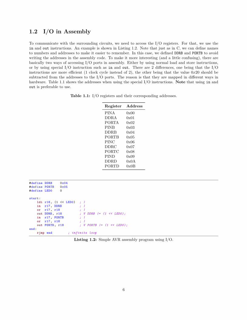
To communicate with the surrounding circuits, we need to access the I/O registers. For that, we use thein and out instructions. An example is shown in Listing 1.2. Note that just as in C, we can define namesto numbers and addresses to make it easier to remember. In this case, we defined DDRB and PORTB to avoidwriting the addresses in the assembly code. To make it more interesting (and a little confusing), there arebasically two ways of accessing I/O ports in assembly. Either by using normal load and store instructions,or by using special I/O instruction such as in and out. There are 2 differences, one being that the I/Oinstructions are more efficient (1 clock cycle instead of 2), the other being that the value 0x20 should besubtracted from the addresses to the I/O ports. The reason is that they are mapped in different ways inhardware. Table 1.1 shows the addresses when using the special I/O instructions. Note that using in andout is preferable to use.
Table 1.1: I/O registers and their corresponding addresses.
Listing 1.2: Simple AVR assembly program using I/O.
6
1.3 Measuring Execution Time
Every instruction takes a certain amount of clock cycles. We can use that information in order to evaluatethe execution time of a program. Some instructions takes different amount of clock cycles based on theoutcome. For example, a branch instruction takes 1 clock cycle if the branch is not taken, and 2 clock cyclesif it is. Analyzing the program in Listing 1.3 yields the result shown in Table 1.2. Note that in order toanalyze the program, we must unroll the loop, counting clock cycles based on if the branch is taken or not.The total execution time (before the infinite loop) is 9 clock cycles. Running at 16 MHz, this yields
9 · 116 M = 562.5 ns.
start:ldi r16, 1 ; load 1 into register 16ldi r17, 13 ; load 13 into register 17loop:
add r17, r16 ; add r17 and r16, save result in r17 (r17++)cpi r17, 15 ; compare r17 with the values 15brne loop ; jump to loop if r17 != 15
The general formula for calculating the average execution time of a single round in a loop (say, a for-loop)is
n − 1n
· p + 1n
· q, (1.1)
where n is the number of rounds, p is the number of clock cycles in a round when the branch is taken, andq is the number of clock cycles during the last round (branch not taken). Using the formula for the loop inListing 1.3, we get
2 − 12
· (1 + 1 + 2) + 12
· (1 + 1 + 1) = 12
· 4 + 12
· 3 = 3.5.
7
That is, the average execution time is 3.5 clock cycles. Running for 2 rounds yields 7 clock cycles, whichmatches the number in Table 1.2. For very long loops, the last round does not affect the average time verymuch. For example, running the same loop 100 times instead would yield
99100
· 4 + 1100
· 3 = 3.99,
which is basically 4 clock cycles per round, which we get if do not take into account that the last branchinstruction only takes 1 clock cycle. In general, for large numbers, n, we get
limn→∞
n − 1n
· p + 1n
· q = p.
What constitutes as a large number depends on the application. Make sure not to approximate too early, oryou may end up with a completely wrong estimation.
8
1.4 Exercises
Answers to the questions can be found in Appendix B.1.
Assembly Basics
1.1 Write an assembly program that loads the values 3 and 4 into register r16 and r17, respectively. Addthe two numbers and store the result in register r17.
1.2 Assume a user have entered their age in a program. The value is stored in register r16. Write aprogram such that if the age is above or equal to 18, you store the value 1 in register r24, otherwiseyou store the value 2 in r24. After the check, you shall just enter an infinite loop.
1.3 Write a program that checks if a button is pressed. If it is, an LED shall be turned on, otherwise theLED shall be turned off. The button is connected on pin 2 (3rd pin) at address 0x12. The LED isconnected on pin 1 (2nd pin) at address 0x15. Remember to not change the other pins as they maybe used for other devices. The code should run in an infinite loop.
1.4 Translate the following C program into AVR assembly. Assume that the global variable input islocated in register r20, and that a is located in register r24.#include <avr/io.h>
char input;
int main(){
uint8_t a;if (input < 12) {
a = 3;} else if (input == 12) {
a = 2;} else {
a = 5; // input > 12}
while (1); // infinite loop}
Listing 1.4: Small C program.
1.5 Your friend Dan recently attended a course in cryptography at LTH. He now believes that he knowsenough crypto and decides to implement his own encryption algorithm. He wants to run his code onhis smart watch, using an AVR processor, but unfortunately his code (Listing 1.5) is just too slow. Heknows that you are taking a course writing super fast code in assembly, hence he asks you for yourassistance.
9
int main(){
char msg;char msg_enc;
msg_enc = msg;for (int i = 0; i < 17; i++) {
msg_enc |= (msg >> 2); // shift msg 2 steps , then OR it in with msg_encmsg_enc <<= 3; // shift msg_enc 3 steps to the leftmsg_enc ^= msg; // xor with msg
}}
Listing 1.5: Super unsafe encryption.
Help your friend Dan speed the code up by implementing it in AVR assembly. Note: You should neverimplement your own encryption algorithms as they will always fail, i.e., Dan did not learn anything inthe crypto course.
Assume that msg is located in register r16 and msg_enc in register r24.
Performance Analysis
1.6 Write an assembly program that takes exactly 302 clock cycles to execute.
1.7 Given the following program,start:
ldi r16, 10
loop1:ldi r17, 255loop2:
dec r17brne loop2
dec r16brne loop1
end:rjmp end
Listing 1.6: Assembly loops.
(a) What does the code do?
(b) Write the corresponding C code using 2 loops
(c) Write the corresponding C code using 1 loop
(d) How many clock cycles does it take before end is reached? Approximate the clock cycles in theloops. That is, do not use Equation 1.1.
1.8 Given the following program,
10
start:ldi r16, 255
loop1:ldi r17, 10loop2:
dec r17brne loop2
dec r16brne loop1
end:rjmp end
Listing 1.7: Assembly loops revisited.
(a) How many clock cycles does the program take now, using approximations in the loops?
(b) How much does it differ from the previous program?
(c) Why is this?
11
1.5 Lab Exercises
1.5.1 Hello, Assembly
Just as always when we are to try new things, we implement a simple program as a sanity check. Here, wewill use the AVR assembly language to blink an LED.
Tasks:
• Create a new project in Atmel Studio, choose “AVR Assembler”, under the “Assembler” tab to theleft, instead of “C/C++”.
Home Assignment 1.1How many clock cycles are needed if a delay of 0.1 s is desired with a clock frequency of 16MHz?
Home Assignment 1.2How many bits do we need to count to the value above?
Home Assignment 1.3How many registers do we need for the delay of 0.1 s?
Home Assignment 1.4Write a snippet of assembly code that delays the program for roughly 0.1 s. Remember thatthe jump instructions also take time to execute.
Home Assignment 1.5How do you turn on LED 2 on port B in assembly? Remember to set the direction to an output.Refer to Appendix A for instructions.
• Use your delay code to create a program that blinks an LED at 5 Hz.
Lab Question 1.1How can you use your delay code in order to create arbitrary delays? What is the limitation?
• Make the LED blink at 1 Hz instead.
You are now done with this part, show your work to a lab assistant! ✓
12
Chapter 2
Memory Management andSubroutines
In this chapter a couple of important topics will be addressed. The first section will cover how to read andwrite data to and from the RAM. After this the stack will be introduced and how one can use it. The lastsection will treat subroutines.
2.1 Accessing the RAM
The fact that the AVR processor’s work registers are merely eight bits long should by this stage be wellknown. That means that the largest integer that fit in them are 255. The RAM of the microcontroller is 16kB. How is it then possible to use the entire memory space? Of course, the designers of the processor had asolution. A couple of the work register can be used as one 16 bit register, namely r26 and r27. The same istrue for r28-r29 and r30-r31. The register pairs are named X, Y and Z. See Figure 2.1 below.
r0 r8 r16 r24
r1 (=0) r9 r17 r25
r2 r10 r18
r3 r11 r19
r4 r12 r20
r5 r13 r21
r6 r14 r22
r7 r15 r23
r26 (XL)
r27 (XH)
r28 (YL)
r29 (YH)
r30 (ZL)
r31 (ZH)
X register
Y register
Z register
Figure 2.1: The register file in the processor with the X, Y and Z register highlighted.
To access the register one can use the macros in Table 2.1.
13
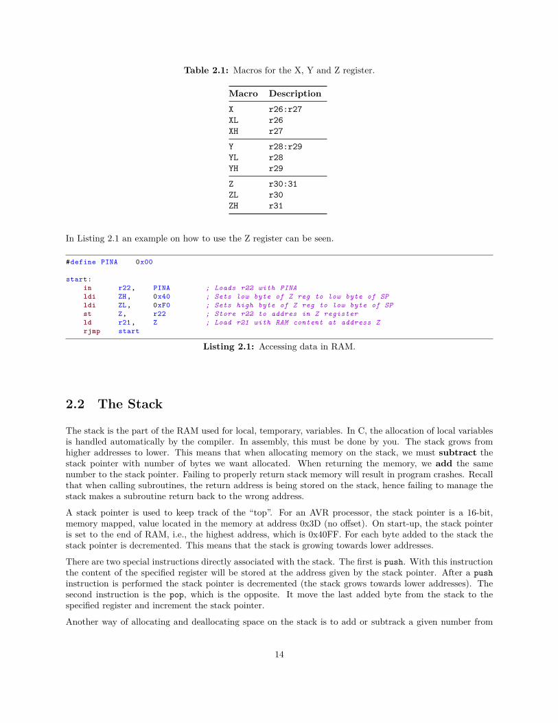
Table 2.1: Macros for the X, Y and Z register.
Macro DescriptionX r26:r27XL r26XH r27
Y r28:r29YL r28YH r29
Z r30:31ZL r30ZH r31
In Listing 2.1 an example on how to use the Z register can be seen.
#define PINA 0x00
start:in r22, PINA ; Loads r22 with PINAldi ZH, 0x40 ; Sets low byte of Z reg to low byte of SPldi ZL, 0xF0 ; Sets high byte of Z reg to low byte of SPst Z, r22 ; Store r22 to addres in Z registerld r21, Z ; Load r21 with RAM content at address Zrjmp start
Listing 2.1: Accessing data in RAM.
2.2 The Stack
The stack is the part of the RAM used for local, temporary, variables. In C, the allocation of local variablesis handled automatically by the compiler. In assembly, this must be done by you. The stack grows fromhigher addresses to lower. This means that when allocating memory on the stack, we must subtract thestack pointer with number of bytes we want allocated. When returning the memory, we add the samenumber to the stack pointer. Failing to properly return stack memory will result in program crashes. Recallthat when calling subroutines, the return address is being stored on the stack, hence failing to manage thestack makes a subroutine return back to the wrong address.
A stack pointer is used to keep track of the “top”. For an AVR processor, the stack pointer is a 16-bit,memory mapped, value located in the memory at address 0x3D (no offset). On start-up, the stack pointeris set to the end of RAM, i.e., the highest address, which is 0x40FF. For each byte added to the stack thestack pointer is decremented. This means that the stack is growing towards lower addresses.
There are two special instructions directly associated with the stack. The first is push. With this instructionthe content of the specified register will be stored at the address given by the stack pointer. After a pushinstruction is performed the stack pointer is decremented (the stack grows towards lower addresses). Thesecond instruction is the pop, which is the opposite. It move the last added byte from the stack to thespecified register and increment the stack pointer.
Another way of allocating and deallocating space on the stack is to add or subtrack a given number from
14
to/from the stack pointer. An example of this is shown in Listing 2.2. The code allocates two bytes on thestack and then stores two bytes of data. This is achieved by:
• loading the stack pointer into r28 and r29 (later used as the Y register),
• subtract two to r28 and r29 (the result is stored in the same registers),
• writing the content of r28 and r29 back to the stack pointer register,
• loading r20 and r21 with data from address 0x63 and 0x59, respectively,
• writing r20 and r21 to the stack, using the Y register, i.e., r28 and r29.
#define STACK_H 0x3E ; Address to the high byte of the stack pointer#define STACK_L 0x3D ; Address to the low byte of the stack pointer#define N_ALLOC 2
warp:.. ; Code to initialize anti-annihilation chamber.in r28, STACK_L ; Load low byte of stack pointer to r28in r29, STACK_H ; Load high byte of stack pointer to r29sbiw Y, N_ALLOC ; Subtract N from the loaded stack pointerout STACK_L, r28 ;out STACK_H, r29 ; Update stack pointerldi r20, 0xCC ; Load r20 with warp core start sequenceldi r21, 0xA1 ; Load r21 with wormhole coordinate system variablestd Y+1, r20 ; Store content of r20 on the stackstd Y+2, r21 ; Store content of r21 on the stack.. ; Warp core calibration code.ret
Listing 2.2: A snippet of assembly code that allocates an array with the size of 2 bytes on the stack.
15
The stack before and after running the snippet of code can be viewed in Figure 2.2. As seen, the stackpointer has been decremented after the execution and the two bytes of data has been added. It should benoted that the stack pointer always points on the next free byte, which is below (lower address) the “top ofstack”1.
0x40FF
0x40FE
0x40FD
0x0002
0x0001
0x0000
Grows in this direction0x40FB
0x40FA
0x40FC
0x40F9
0x40F8
Free
Free
Free
Free
0x40FF
0x40FE
0x40FD
0x0002
0x0001
0x0000
0x40FB
0x40FA
0x40FC
0x40F9
0x40F8
0xA1Stack pointer
0xCC
Free
Top of stack
Stack pointer
0xD5
0x13
0x4F
0xB3
0xD5
0x13
0x4F
0xB3
Free
Free
Free
Free
Free
Free
Free
Top of stack
Figure 2.2: The stack before (left) and after running the code in Listing 2.2.
Whenever the stack has been used, that is, the need for storing data is no longer present, the allocated bytesneed to be deallocated. If this is not done, the stack will keep growing and soon or later it will collide withthe other content stored in the RAM. To return the allocated space, the number of bytes that was allocatedshould be added to the stack pointer. By doing so the memory will be freed up, see Figure 2.3. Do notethat the content of the previously used memory space is still there (but it should be considered to be lost).
1The top of stack is purely imaginary, there is no register in the CPU that contains this address.
16
0x40FF
0x40FE
0x40FD
0x0002
0x0001
0x0000
0x40FB
0x40FA
0x40FC
0x40F9
0x40F8
0x40FF
0x40FE
0x40FD
0x0002
0x0001
0x0000
0x40FB
0x40FA
0x40FC
0x40F9
0x40F8
0xA1
0xCC
Free
0xD5 0xD5
0x13
0x4F
0xB3
Free
Free
Free
Free
0xA1
0xCC
Free
0xD5
0x13
0x4F
0xB3
Free
Free
Free
Free
Stack pointer
Top of stack
Top of stack
Stack pointer
Figure 2.3: The stack before and after (right) the allocated bytes have been “returned”.
17
2.3 Subroutines
Just as we can separate code in different functions in C and Java, assembly lets us separate code in differentsubroutines, using labels. As before, a label can be used both in loops to jump to, but also to declare asubroutine. The difference is how they are used. To jump to a label (say, in a loop), any branch instructionmay be used. When declaring a subroutine, it must be called using the call instruction.
When calling a subroutine, using call, an important thing happens in the processor. The address of theinstruction after the call, which is PC2 + 1 (the digit 2 is a footnote), is pushed on the stack. This isimportant since we must be able to continue where we left off. An example is shown in Listing 2.3.
start:call delay ; delay foreverrjmp start
delay:ldi r16, 100 ; r16 = 100loop:
dec r16 ; r16--brne loop ; loop if r16 != 0
ret ; return from subroutine
Listing 2.3: Calling subroutines in assembly.
As shown in the code, we can use labels in both ways at the same time, here used both for declaring asubroutine, delay, and also for the loop. Every subroutine must end with a ret instruction. This will popthe return address from the stack and jump back to the start routine by setting the program counter tothe popped value. After this, delay will be called again, and again.
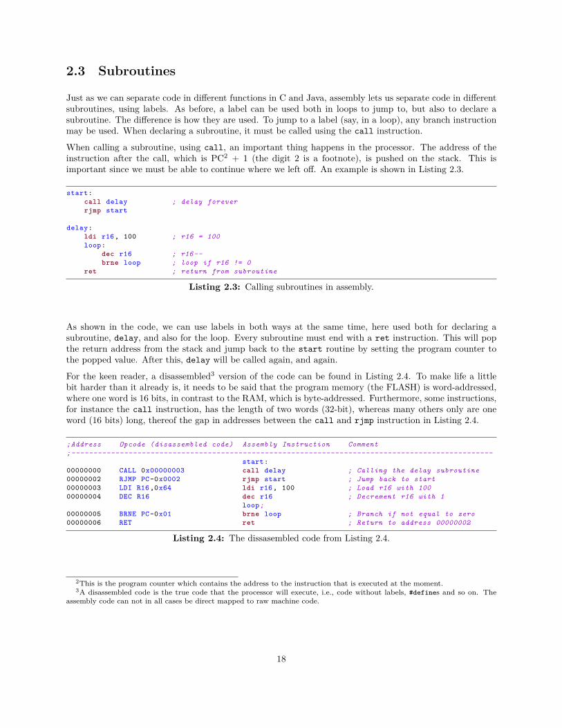
For the keen reader, a disassembled3 version of the code can be found in Listing 2.4. To make life a littlebit harder than it already is, it needs to be said that the program memory (the FLASH) is word-addressed,where one word is 16 bits, in contrast to the RAM, which is byte-addressed. Furthermore, some instructions,for instance the call instruction, has the length of two words (32-bit), whereas many others only are oneword (16 bits) long, thereof the gap in addresses between the call and rjmp instruction in Listing 2.4.
start:00000000 CALL 0x00000003 call delay ; Calling the delay subroutine00000002 RJMP PC-0x0002 rjmp start ; Jump back to start00000003 LDI R16,0x64 ldi r16, 100 ; Load r16 with 10000000004 DEC R16 dec r16 ; Decrement r16 with 1
loop;00000005 BRNE PC-0x01 brne loop ; Branch if not equal to zero00000006 RET ret ; Return to address 00000002
Listing 2.4: The dissasembled code from Listing 2.4.
2This is the program counter which contains the address to the instruction that is executed at the moment.3A disassembled code is the true code that the processor will execute, i.e., code without labels, #defines and so on. The
assembly code can not in all cases be direct mapped to raw machine code.
18
2.3.1 The Anatomy of a Subroutine
A subroutine is a bit more primitive than its high level counterpart in the sense that the programmer needsto do some parts of the compiler’s job. What the programmer needs to do will be addressed in this section.
A subroutine is divided into three parts; a prologue, a body, and an epilogue, see Figure 2.4. Each part hasits specific purpose.
Subroutine Body
Prologue
Epilogue
Figure 2.4: The anatomy of a subroutine.
When a subroutine has been called, it is important the every register, that will be used during the call andwhich content is of importance to the caller after the subroutine has executed, is being saved on the stack.This should, of course, be done in the beginning of the subroutine. The registers are preferably saved withthe push instruction. Furthermore, if more space on the stack is required, it should also be allocated here(for ease of use, after the pushing the registers). This part of the code is referred to as the prologue. InListing 2.5, an example of this is shown. In the subroutine there is a need to save r28 and r29, but not r19.
#define STACK_H 0x3E ; Address to the high byte of the stack pointer#define STACK_L 0x3D ; Address to the low byte of the stack pointer#define N_ALLOC 5
defense_routine:;==================== Start of the prologuepush r28push r29in r28, STACK_L ; Load low byte of stack pointer to r28in r29, STACK_H ; Load high byte of stack pointer to r29sbiw Y, N_ALLOC ; Subtract N_ALLOC from the loaded stack pointerout STACK_L, r28 ;out STACK_H, r29 ; Update stack pointer;==================== End of the prologue
;==================== Beginning of subroutine body....
Listing 2.5: The prologue of an assembly subroutine.
In the part of the routine called the subroutine body, the routine performs its designated task. When this
19
is done, the epilogue starts. The first thing to do here is to free up all memory that has been allocated onthe stack. The second thing is to restore the registers that were pushed on the stack. This is achieved byadding an appropriate value to the stack pointer. When this is done, the stack pointer will be pointing atthe last value that was pushed to the stack in the prologue. When all of this is done, the subroutine canreturn back from where the subroutine was called (with the ret instruction). In Listing 2.6, an example ofan epilogue is shown.
#define STACK_H 0x3E ; Address to the high byte of the stack pointer#define STACK_L 0x3D ; Address to the low byte of the stack pointer#define N_ALLOC 5
defense_routine:...;==================== End of the subroutine body
;==================== Beginning of the epiloguein r28, STACK_L ; Load low byte of stack pointer to r28in r29, STACK_H ; Load high byte of stack pointer to r29adiw Y, N_ALLOC ; Add N_ALLOC to the loaded stack pointerout STACK_L, r28 ;out STACK_H, r29 ; Update stack pointerpop r29pop r28ret;==================== End of the epilogue and the subroutine
Listing 2.6: The epilogue of an assembly subroutine.
20
2.4 Lab Exercises
2.4.1 Dynamic Memory Allocation
Sometimes, the general purpose working registers are not enough to store the data you use. Assume thatyou are sampling your beautiful singing voice from a microphone over a time period. With only 32 registersin the AVR, we will run out of space pretty quick. In such a case the RAM is utilized. For global variablesthe .data section is used. For local variables (inside a function) the data is usually stored on the stack.
The authors recognize that this assignment is a bit artificial, but it highlights some interesting points studentsneed to know, in a simple way.
Tasks:
• Create a new “Assembler” project in Atmel Studio.
Home Assignment 2.1How do you allocate 10 integers on the stack?
• Write an assembly subroutine that allocates an array of 5 bytes on the stack.
Lab Question 2.1What is the value of the stack pointer directly after allocation? Use the debugger.
Home Assignment 2.2If you allocate an array of bytes on the stack, and the stack pointer after allocation is 0x40E0,what is the address of the value at index 3?
• In the subroutine, sample the state of the buttons B1 to B6 in a loop and save the five latest in thearray. The first sample shall be placed at index zero (arr[0]), the fifth sample at index four. Aftersaving the values, simply return from the subroutine.
Remember that when you borrow something, you must return it.
• In the main function, call your subroutine in a forever-loop.
• Start the debugger and step through each sample to verify that you can read the values of the buttons.Also check the stack to verify that the samples are placed at the correct addresses.
Lab Question 2.2What happens if we do not return the allocated memory in the subroutine?
21
Lab Question 2.3Do we need to store the values in the allocated array? What happens if we just store the valuesrandomly on the stack?
You are now done with this part, show your work to a lab assistant! ✓
22
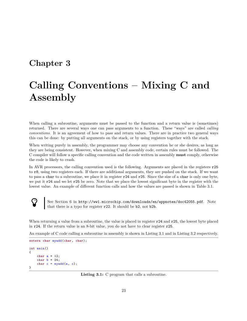
Chapter 3
Calling Conventions – Mixing C andAssembly
When calling a subroutine, arguments must be passed to the function and a return value is (sometimes)returned. There are several ways one can pass arguments to a function. These “ways” are called callingconventions. It is an agreement of how to pass and return values. There are in practice two general waysthis can be done: by putting all arguments on the stack, or by using registers together with the stack.
When writing purely in assembly, the programmer may choose any convention he or she desires, as long asthey are being consistent. However, when mixing C and assembly code, certain rules must be followed. TheC compiler will follow a specific calling convention and the code written in assembly must comply, otherwisethe code is likely to crash.
In AVR processors, the calling convention used is the following. Arguments are placed in the registers r25to r8, using two registers each. If there are additional arguments, they are pushed on the stack. If we wantto pass a char to a subroutine, we place it in register r24 and r25. Since the size of a char is only one byte,we put it r24 and we let r25 be zero. Note that we place the lowest significant byte in the register with thelowest value. An example of different function calls and how the values are passed is shown in Table 3.1.
See Section 6 in http://ww1.microchip.com/downloads/en/appnotes/doc42055.pdf. Notethat there is a typo for register r22. It should be b2, not b2b.
When returning a value from a subroutine, the value is placed in register r24 and r25, the lowest byte placedin r24. If the return value is an 8-bit value, you do not have to clear register r25.
An example of C code calling a subroutine in assembly is shown in Listing 3.1 and in Listing 3.2 respectively.extern char myadd(char, char);
Table 3.1: Function calls with arguments places in registers.
Function call Register valueschar a = 0x12; r25 = 0x00func(a) r24 = 0x12char a = 0x1234; r25 = 0x12func(a); r24 = 0x34char a = 0x23; r25 = 0x00char b = 0x42; r24 = 0x23func(a, b); r23 = 0x00
r22 = 0x42
.global myadd
myadd:; input arguments are in r24 and r22add r24, r22 ; add arguments and store the result in r24 (return value)ret ; return from subroutine
Listing 3.2: A subroutine adding numbers, being called from C.
Note the two keywords, extern in the C code, and .global in the assembly code. The extern keyword tellsthe compiler that the function is defined somewhere else. In this case, in the assembly file. The .globalkeyword lets the compiler know that the function shall be accessible outside the assembly file. Without this,the C program will not “see” the function.
3.1 Register Usage
All registers, r0 to r31 may be used in a subroutine, but some registers need to be restored because thecaller function (C code) expects the values in those registers not to change, see Table 3.2. The registers tobe saved shall be pushed on the stack in the subroutine prologue, and popped off the stack, in the epilogue.
For more details, see Section 5 in http://ww1.microchip.com/downloads/en/appnotes/doc42055.pdf. Note that there is a typo in the table. The next to last register should ber30, not r0.
Table 3.2: Register usage in assembly, when called from C code.
Register Usager0 Save and restore if usingr1 Always 0, clear before return if usingr2-r17 Save and restore if usingr28 Save and restore if usingr29 Save and restore if usingr18-r27 Can freely use30 Can freely use31 Can freely use
25
3.2 Exercises
Answers to the questions can be found in Appendix B.2.
Calling Conventions
3.1 Your cannibal friend recently installed a security system, preventing the law enforcement from accessinghis personal belongings. Help him finish the last piece of code, the compare function checking thepassword. Implement the subroutine in AVR assembly language, following all conventions. The Ccode calling the compare routine, strcmp, is shown below. Note that the arguments to the comparefunction are pointers to the strings. All strings are assumed to be NULL-terminated.#include <avr/io.h>#include <stdio.h>
extern uint8_t compare(char *, char *);
char password = "<hidden>";
int main(){
// create an empty array (buffer)char input[32];
// prompt user for password , over UARTprintf("Enter password: ");
// read user password and store it in "input".fgets(input, 32, stdin);
// check passworduint8_t res = strcmp(input, password);
if (res == 0) {printf("Access granted! Welcome Dr. Lecter.");
} else {printf("Access denied!");
}}
3.2 Your boyfriend, Xavier, is known for visiting morally questionable websites on the deep web from timeto time. His computer recently got infected by the GandCrab1 ransomware, encrypting all of his files.Albeit lazy, fortunately he had backups of his files. The problem is that the software for backing upfiles got encrypted as well. He decided to implement his own restore program, fetching the backed upfiles from the cloud2. He realizes that the function copying the files from the cloud to his computeris too slow, and asks for your help. Implement the strcpy function in AVR assembly, following allconventions, that copies an array of bytes from one address to another address.
1https://www.acronis.com/en-us/articles/gandcrab/2The cloud is just someones else’s computer
if ((dir = opendir("C:\\")) != NULL) {// get all files in the C:\ folderwhile ((ent = readdir(dir)) != NULL) {
// open and read the local encrypted filefile = fopen(ent->d_name, "rw");char local_content[MAX_SIZE];fread(local_content, MAX_SIZE, 1, file);
// read the data from the backed up filechar *cloud_content = get_content_from_cloud(ent->d_name);
// copy the cloud data to the local file// TODO: implement in AVR asmstrcpy(local_content, cloud_content);
// save the new filefwrite(file, MAX_SIZE, 1, local_content);
}}
}
27
3.3 Lab Exercises
3.3.1 When Harry Met Sally
Being limited to only write in assembly is daunting for most people (authors excluded), and most would liketo write only the critical parts in assembly but the rest in a more user friendly language. Just as we can callJava functions from C, C from Python, and C from Matlab, we can of course call assembly from C (and viceversa).
In this assignment, we will explore the combination of C and assembly.
Tasks:
• Create a new “GCC C Executable” project in Atmel Studio.
• Write a program that blinks an LED if a button is pressed. That is, if a button is pressed, you shall callled_on() and led_off() with a delay after both functions, use 500 ms. Note that the two functionsare not yet implemented, thus you will need to implement them in assembly. On the top of your C-file,add
– extern void led_on(char),
– extern void led_off(char),
– extern char check_button(char).
This tells the compiler that the functions are defined elsewhere.
Remember to specify the data direction, to make the pins connected to the LEDs outputs.
Remember to define F_CPU to 16 MHz before including the <util/delay.h> file.
• Right-click the project name in the solution explorer and select add -> New Item... then selectPreprocessing Assembler File (.S) to add a new assembly file.
Home Assignment 3.1In AVR assembly, how do you declare a subroutine? How do you call it?
Home Assignment 3.2In AVR assembly, how are arguments passed to and returned from a subroutine?
• Declare the three subroutines and implement them following all conventions.
28
Lab Question 3.1When calling the subroutine, led_on, what is being pushed to the stack and why?
Lab Question 3.2When the ret instruction is executed, what happens with the stack pointer?
Lab Question 3.3In the check_button subroutine, comment out the instruction where you place the return valuein r24 and run the code. Does the LED blink? If so, why?
• Run the code in a debugger to verify that the code executes as expected.
When debugging, it is good to comment the _delay_ms calls to avoid waiting.
3.3.2 Hello, Mr. Anderson
A NeoPixel, the number 4 in Figure 1, is a single pixel with adjustable RGB colors controlled via a serialprotocol. The pixels are chainable, meaning that the output of one pixel can be connected to the input ofanother pixel in order to have several controllable pixels, not needing more outputs on the microcontroller.This allows for the engineer to create all kinds of shapes and circuits without wasting resources.
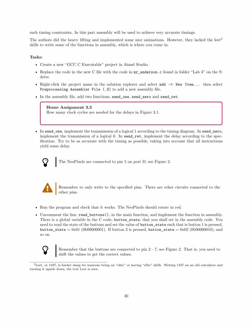
Controlling a NeoPixel can be done using only a single pin on the microcontroller. This means that we onlycan send binary values, ones and zeros. The NeoPixel needs to be able to distinguish between sending dataand not sending data, hence sending ones and zeros can not be done by only setting the output pin high orlow. Instead, we need to send the data in a pattern, see Figure 3.1.
0.35μs 0.70μs0.80μs 0.60μs
Sending 0 Sending 1 Sending ret code
50μs
Figure 3.1: A picture of the timings for sending data to a NeoPixel.
As previously stated, sometimes when facing tough timing constraints, a high-level language might not meetthe requirements and the programmer must utilize the power of assembly programming. The NeoPixels have
29
such timing constraints. In this part assembly will be used to achieve very accurate timings.
The authors did the heavy lifting and implemented some nice animations. However, they lacked the leet3
skills to write some of the functions in assembly, which is where you come in.
Tasks:
• Create a new “GCC C Executable” project in Atmel Studio.
• Replace the code in the new C file with the code in mr_anderson.c found in folder “Lab 3” on the S:drive.
• Right-click the project name in the solution explorer and select add -> New Item... then selectPreprocessing Assembler File (.S) to add a new assembly file.
• In the assembly file, add two functions, send_one, send_zero and send_ret.
Home Assignment 3.3How many clock cycles are needed for the delays in Figure 3.1.
• In send_one, implement the transmission of a logical 1 according to the timing diagram. In send_zero,implement the transmission of a logical 0. In send_ret, implement the delay according to the spec-ification. Try to be as accurate with the timing as possible, taking into account that all instructionsyield some delay.
The NeoPixels are connected to pin 5 on port D, see Figure 2.
Remember to only write to the specified pins. There are other circuits connected to theother pins.
• Run the program and check that it works. The NeoPixels should rotate in red.
• Uncomment the line, read_buttons(), in the main function, and implement the function in assembly.There is a global variable in the C code, button_state, that you shall set in the assembly code. Youneed to read the state of the buttons and set the value of button_state such that is button 1 is pressed,button_state = 0x01 (0b00000001). If button 2 is pressed, button_state = 0x02 (0b00000010), andso on.
Remember that the buttons are connected to pin 2 - 7, see Figure 2. That is, you need toshift the values to get the correct values.
3Leet, or 1337, is hacker slang for someone being an “elite” or having “elite” skills. Writing 1337 on an old calculator andturning it upside down, the text Leet is seen.
30
Table 3.3: Actions for the animation.
Button ActionB1 Set color to redB2 Set color to greenB3 Set color to blueB4 Set direction to rightB5 Pause animationB6 Set direciton to left
To access the button_state variable in assembly, add “.extern button_state”. Youcan use the name when storing a value to it, e.g., “sts button_state, r16”, where r16contains the value to be written.
• Run the program. See Table 3.3 for the different control options.
You are now done with this part, show your work to a lab assistant! ✓
31
Chapter 4
Optional:Black Magic – The DarkSide of Programming
Using C and/or assembly language gives the programmer (almost) full access to the system. This is sometimesnecessary in order to solve specific problems, but may sometimes cause more harm than good. For example,dealing with arrays in C requires more attention of the programmer than in Java. In Java, if an integer arrayof 10 elements is declared and the programmer tries to add 11 integers, a “java.lang.ArrayIndexOutOfBoundsException”exception is thrown. Performing the same test in C results in (usually) nothing. The program seems to work,but sometimes it will crash. There are no security mechanisms preventing the programmer from doing thingsthey should not. What happens is that the array will be overflowed and data located next to the array inthe memory gets overwritten, without warning.
When a programmer needs some storage to save data, e.g., user names and passwords, they create an array,or a buffer. If the buffer is overflowed, it is called a buffer overflow, or a stack overflow when it happens tolocal data stored on the stack.
An example of a stack overflow is shown in Listing 4.1. Here, we see the dangers of a common mistake, anoff-by-one error, where the programmer loops one time too many. This results in overwriting the accessvariable, since it is located right after the buffer buff. The access variable will be given the value 10 afterthe loop.int main(){
// add values to array , but loops 1 time too manyfor (int i = 0; i <= 10; i++) {
buff[i] = i;}
if (access == 0) {exit(0); // quit gracefully
} else {// release the kraken...
}
Listing 4.1: Showing a simple buffer overflow.
32
4.1 Lab Exercises
4.1.1 Never Trust User Input
Having full access to the memory is both a blessing and a sin. Here, we will explore the dark side ofprogramming.
Tasks:
• Create a new “GCC C Executable” project in Atmel Studio.
• Copy the contents of the file black_magic.c from the folder “Lab 3” on the S: drive and paste it in toyour newly created C file.
• Make sure to remove both compiler optimization, and the “Garbage collect unused sections” under theLinker optimization tab, in the project settings.
Lab Question 4.1What does the code do?
Lab Question 4.2Without running the code, does it seem like the function hacked is ever called?
Lab Question 4.3Run the code once, what happens?
• Place a breakpoint at secure_function and run the debugger.
Lab Question 4.4When calling the secure_function function, what will be pushed to the stack and at whichaddresses?
• Step into the secure_function function by clicking “Step Into” or by pressing F11. Then, view thediassembly and step into the strcpy function. Continue to step inside strcpy and closely follow whathappens in the memory.
Lab Question 4.5At which addresses do strcpy copy the last values? Is this correct? If not, is somethingoverwritten?
33
Lab Question 4.6As you exit strcpy and executing the ret instruction in secure_function, what is the returnaddress? Where do we end up?
When debugging, it is good to comment the _delay_ms calls to avoid waiting.
You are now done with this part, show your work to a lab assistant! ✓
34
Appendix A
AVR Instruction Set
An excerpt of AVR assembly instructions is shown in Table A.1. Rd and Rr are registers, usually r0 to r31,and Imm is an immediate value which may be given in decimal, hexadecimal or in binary. One may also usemathematical operations for the immediate value, such as “+”, “-”, “«” and so on.
Note that not all registers can be used in all instructions. For information regarding valid registers and howmany clock cycles the instructions take, see the documentation at https://www.microchip.com/webdoc/avrassembler/avrassembler.wb_instruction_list.html.
breq label Jump to label if Rd = Rrbrlo label Jump to label if Rd < Rrbrne label Jump to label if Rd != Rrbrsh label Jump to label if Rd >= Rrrjmp label Jump to label
Subroutine call label Call subroutine labelret Return form subroutine
Memory
push Rr Push value of register Rr on stackpop Rd Pop top of stack and store value in Rdld Rd, X/Y/Z Load value into Rd from address in X, Y or Zldi Rd, Imm Rd = Immlds Rd, K Load value into Rd from address Kst Y, Rr Store value of Rr to address in Ystd Y+k, Rr Store value of Rr to addres in Y + ksts Imm, Rr Store value of Rr to address Imm
I/O in Rd, Imm Read from I/O device at address Imm, store in Rdout Imm, Rr Write value of Rr to I/O device at address Imm
Othermov Rd, Rr Copy value from Rr to Rdmovw Rd, Rr Copy word from Rr to Rdnop No operation, do nothing
36
Appendix B
Answers to Exercise Questions
B.1 Exercise 1
Click here to fast travel back to Section 1.4, price: 1 bit.
1.1 One possible solution is shown below.start:
ldi r4, 3ldi r5, 4add r5, r4
end:rjmp end
1.2 One possible solution is shown below.start:
cpi r16, 18 ; compare r16 with 18brlo lower ; if r16 < 18, jump to lowerldi r24, 1 ; else: store 1 in r24 and jump to endrjmp end
lower:ldi r24, 2 ; store 2 in r24, then go to end
end:rjmp end
1.3 One possible solution is shown below.
37
#define BTN 0x12#define LED 0x15
start:in r16, BTN ; read buttonsldi r17, 1 << 2 ; mask for button 2, 0b00000100and r16, r17 ; mask out the state of button 2breq off ; if button is not pressed , turn off LED
; else, turn it onldi r16, LED ; read the LED stateldi r17, 1 << 1 ; mask for LED 1or r16, r17 ; set bit for LED 1 to highout LED, r16 ; write back the value to the output , turning on LED 1rjmp start ; go back to beginning
off: ; turn off ledldi r16, LED ; read the LED stateldi r17, ~(1 << 1) ; mask for clearing bit 1and r16, r17 ; clear bit 1out LED, r16 ; write back to memoryrjmp start ; go back to beginning
start:ldi r17, 17 ; loop variable , i = 17mov r24, r16 ; copy msg to msg_enc
loop:mov r16, r18 ; copy msg to r18lsr r18 ;lsr r18 ; shift 2 steps to the right (msg >> 2)or r24, r18 ; msg_enc |= (msg >> 2)lsl r24lsl r24 ; shift to the leftlsl r24 ; msg_enc = msg_enc << 3eor r24, r16 ; msg_enc ^= msg
dec r17 ; i--brne loop ; loop while i > 0
end:rjmp end
1.6 One possible solution is shown below.start:
ldi r2, 100loop:
dec r2brne loopnop
end:rjmp end
1.7 (a) The code loops 2550 times.
(b) The solution is shown below.for (int i = 0; i < 10; i++) {
for (int j = 0; j < 255; j++) {// chill
}}
(c) The solution is shown below.for (int i = 0; i < 2550; i++) {
// chill}
39
(d) The innermost loop takes 3 clock cycles on average. It loops 255 times, which gives 765 clockcycles in total. The outer loop runs 10 times. The number of clock cycles is dominated by theinner loop, hence we can exclude the extra cycles to branch and to decrement r16. Since theouter loop runs the inner loop every iteration, we have in total 765 · 10 = 7650 clock cycles,approximately.
If we do include the branch and decrement, we get 768 · 10 = 7680.
1.8
(a) Now, using the same approximation, we have that the inner loop takes 3 clock cycles, and runs10 times. This gives 30 clock cycles in total. The outer loop runs 255 times. Including the branchand decrement, we get 255 ∗ 33 = 8415.
(b) It differs with about 750 clock cycles.
(c) The main reason is that in the first case, the loop runs so many times that the difference in clockcycles for the branch instruction does not matter, whereas in the second case, it only loops 10times. The branch instruction takes 2 clock cycles 9 of the times, and only 1 clock cycle the lastround. Since this loop is being run 255 times, the small impact of the branch’s cycles make alarge difference. In the second case, we would need to calculate the true average of the loop, usingthe Equation 1.1.
B.2 Exercise 3
Click here to fast travel back to Section 3.2, price: 1 bit.