+ All Categories
Home > Documents > Lab - Building a Simple Network · Lab - Building a Simple Network © 2013 Cisco and/or its...

Lab - Building a Simple Network · Lab - Building a Simple Network © 2013 Cisco and/or its...

Date post: 18-May-2018
Category:
Upload: dinhnhu
View: 218 times
Download: 2 times
Share this document with a friend
14
© L T A O B © 2013 Cisco and Lab - Bu Topology Addressing D S1 S2 PC PC Objectives Part 1: Se Identi Cable Part 2: Co Enter Verify Part 3: Co Config Save Displa Displa Displa Backgroun Networks simple ne d/or its affiliates. uilding a g Table Device V V C-A N C-B N et Up the Net fy cables and e a physical la onfigure PC static IP add y that PCs can onfigure and gure each sw the running c ay the running ay the IOS ve ay the status nd / Scenar are construc etwork with tw All rights reserve a Simple Interface LAN 1 LAN 1 IC IC twork Topolo d ports for use ab topology. Hosts ress informat n communica d Verify Basic witch with host configurations g switch confi ersion for the of the interfac rio ted of three m wo hosts and t ed. This docume e Networ IP A N/A N/A 192.16 192.16 ogy (Etherne e in the netwo tion on the LA ate using the p c Switch Set tname, local p s. iguration. running switc ces. major compon two switches. ent is Cisco Publi rk Address N N 68.1.10 2 68.1.11 2 et only) ork. AN interface o ping utility. ttings passwords, a ch. nents: hosts, s You will also ic. Subnet Mas N/A N/A 255.255.255.0 255.255.255.0 of the hosts. and login bann switches, and o configure ba sk Defau N/A N/A 0 N/A 0 N/A ner. d routers. In th asic settings i P ult Gateway his lab, you w ncluding host Page 1 of 14 will build a tname,
Transcript

©

L

T

A

O

B

© 2013 Cisco and

Lab - Bu

Topology

Addressing

D

S1

S2

PC

PC

Objectives

Part 1: Se

Identi

Cable

Part 2: Co

Enter

Verify

Part 3: Co

Config

Save

Displa

Displa

Displa

Backgroun

Networks simple ne

d/or its affiliates.

uilding a

g Table

Device

V

V

C-A N

C-B N

et Up the Net

fy cables and

e a physical la

onfigure PC

static IP add

y that PCs can

onfigure and

gure each sw

the running c

ay the running

ay the IOS ve

ay the status

nd / Scenar

are construcetwork with tw

All rights reserve

a Simple

Interface

LAN 1

LAN 1

IC

IC

twork Topolo

d ports for use

ab topology.

Hosts

ress informat

n communica

d Verify Basic

witch with host

configurations

g switch confi

ersion for the

of the interfac

rio

ted of three mwo hosts and t

ed. This docume

e Networ

IP A

N/A

N/A

192.16

192.16

ogy (Etherne

e in the netwo

tion on the LA

ate using the p

c Switch Set

tname, local p

s.

iguration.

running switc

ces.

major compontwo switches.

ent is Cisco Publi

rk

Address

N

N

68.1.10 2

68.1.11 2

et only)

ork.

AN interface o

ping utility.

ttings

passwords, a

ch.

nents: hosts, sYou will also

ic.

Subnet Mas

N/A

N/A

255.255.255.0

255.255.255.0

of the hosts.

and login bann

switches, ando configure ba

sk Defau

N/A

N/A

0 N/A

0 N/A

ner.

d routers. In thasic settings i

P

ult Gateway

his lab, you wncluding host

Page 1 of 14

will build a tname,

Lab - Building a Simple Network

© 2013 Cisco and/or its affiliates. All rights reserved. This document is Cisco Public. Page 2 of 14

local passwords, and login banner. Use show commands to display the running configuration, IOS version, and interface status. Use the copy command to save device configurations.

You will apply IP addressing for this lab to the PCs to enable communication between these two devices. Use the ping utility to verify connectivity.

Note: The switches used are Cisco Catalyst 2960s with Cisco IOS Release 15.0(2) (lanbasek9 image). Other switches and Cisco IOS versions can be used. Depending on the model and Cisco IOS version, the commands available and output produced might vary from what is shown in the labs.

Note: Make sure that the switches have been erased and have no startup configurations. Refer to Appendix A for the procedure to initialize and reload a switch.

Required Resources

2 Switches (Cisco 2960 with Cisco IOS Release 15.0(2) lanbasek9 image or comparable)

2 PCs (Windows 7, Vista, or XP with terminal emulation program, such as Tera Term)

Console cables to configure the Cisco IOS devices via the console ports

Ethernet cables as shown in the topology

Part 1: Set Up the Network Topology (Ethernet only)

In Part 1, you will cable the devices together according to the network topology.

Step 1: Power on the devices.

Power on all devices in the topology. The switches do not have a power switch; they will power on as soon as you plug in the power cord.

Step 2: Connect the two switches.

Connect one end of an Ethernet cable to F0/1 on S1 and the other end of the cable to F0/1 on S2. You should see the lights for F0/1 on both switches turn amber and then green. This indicates that the switches have been connected correctly.

Step 3: Connect the PCs to their respective switches.

a. Connect one end of the second Ethernet cable to the NIC port on PC-A. Connect the other end of the cable to F0/6 on S1. After connecting the PC to the switch, you should see the light for F0/6 turn amber and then green, indicating that PC-A has been connected correctly.

b. Connect one end of the last Ethernet cable to the NIC port on PC-B. Connect the other end of the cable to F0/18 on S2. After connecting the PC to the switch, you should see the light for F0/18 turn amber and then green, indicating that the PC-B has been connected correctly.

Step 4: Visually inspect network connections.

After cabling the network devices, take a moment to carefully verify the connections to minimize the time required to troubleshoot network connectivity issues later.

L

©

P

S

Lab - Buildin

© 2013 Cisco and

Part 2: C

Step 1: Co

a. Click

b. In the

Note:chang

g a Simple N

d/or its affiliates.

Configure

onfigure sta

the Windows

e Network and

If the Controge this option

Network

All rights reserve

e PC Host

tic IP addre

s Start icon a

d Internet sec

ol Panel displato display by

ed. This docume

ts

ess informa

and then selec

tion, click the

ays a list of icy Category.

ent is Cisco Publi

ation on the

ct Control Pa

e View netwo

cons, click the

ic.

PCs.

anel.

ork status an

e drop-down o

d tasks link.

option next to

P

the View by

Page 3 of 14

: and

L

©

Lab - Buildin

© 2013 Cisco and

c. In the

d. The NConn

g a Simple N

d/or its affiliates.

e left pane of t

Network Connnection interfa

Network

All rights reserve

the Network a

nections windoace and selec

ed. This docume

and Sharing C

ow displays tct Properties

ent is Cisco Publi

Center window

he available is.

ic.

w, click the C

interfaces on

Change adapt

the PC. Righ

P

ter settings l

ht-click the Lo

Page 4 of 14

link.

ocal Area

L

©

Lab - Buildin

© 2013 Cisco and

e. Selec

Note:windo

g a Simple N

d/or its affiliates.

ct the Internet

You can alsoow.

Network

All rights reserve

t Protocol Ve

o double-click

ed. This docume

ersion 4 (TCP

k Internet Pro

ent is Cisco Publi

P/IPv4) option

otocol Versio

ic.

n and then cl

on 4 (TCP/IPv

ick Propertie

v4) to display

P

es.

y the Properti

Page 5 of 14

es

L

©

S

Lab - Buildin

© 2013 Cisco and

f. Click defau

Note:gatewAddre

g. After windo

h. Repe

Step 2: Ve

Use the c

a. From press

g a Simple N

d/or its affiliates.

the Use the flt gateway.

In the aboveway has not bessing Table o

all the IP infoow to assign t

at the previou

rify PC sett

ommand prom

PC-A, click th Enter.

Network

All rights reserve

following IP

e example, theeen entered, on page 1 for

rmation has bthe IP address

us steps to en

tings and co

mpt (cmd.exe

he Windows

ed. This docume

address radi

e IP addressbecause ther

r PC-B’s IP ad

been entereds to the LAN

nter the IP add

onnectivity.

e) window to

Start icon, ty

ent is Cisco Publi

o button to m

and subnet mre is no routeddress inform

, click OK. Cladapter.

dress informa

.

verify the PC

ype cmd in th

ic.

manually enter

mask have ber attached to

mation.

ick OK on the

ation for PC-B

C settings and

he Search pro

r an IP addre

een entered fothe network.

e Local Area

B.

connectivity.

ograms and

P

ss, subnet ma

or PC-A. The Refer to the

Connection P

.

files box, an

Page 6 of 14

ask, and

default

Properties

d then

L

©

Lab - Buildin

© 2013 Cisco and

b. The ccommhostn

c. Type

Were

If not,

Note:try to help y

g a Simple N

d/or its affiliates.

cmd.exe windomands. Verify ame and the

ping 192.168

the ping resu

troubleshoot

If you did noping PC-A fro

you troublesh

Network

All rights reserve

ow is where yyour PC settiIPv4 address

8.1.11 and pre

ults successfu

t as necessar

ot get a reply fom PC-B. If yoot the proble

ed. This docume

you can enterings by usings information.

ess Enter.

ul?

ry.

from PC-B, tryou are unableem.

ent is Cisco Publi

r commands d the ipconfig

y to ping PC-e to get a rep

ic.

directly to theg /all comman

-B again. If yoply from the re

e PC and viewnd. This comm

ou still do not emote PC, the

P

w the results omand displays

get a reply froen have your

Page 7 of 14

of those s the PC

om PC-B, instructor

Lab - Building a Simple Network

© 2013 Cisco and/or its affiliates. All rights reserved. This document is Cisco Public. Page 8 of 14

Part 3: Configure and Verify Basic Switch Settings

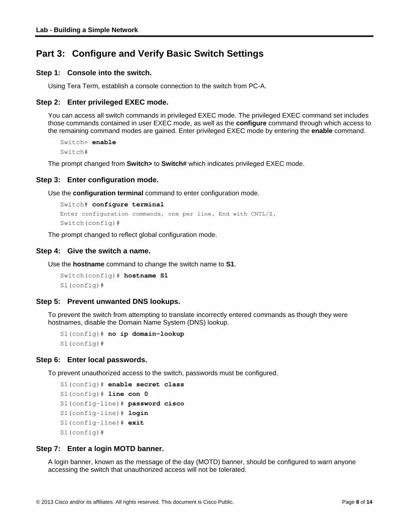
Step 1: Console into the switch.

Using Tera Term, establish a console connection to the switch from PC-A.

Step 2: Enter privileged EXEC mode.

You can access all switch commands in privileged EXEC mode. The privileged EXEC command set includes those commands contained in user EXEC mode, as well as the configure command through which access to the remaining command modes are gained. Enter privileged EXEC mode by entering the enable command.

Switch> enable

Switch#

The prompt changed from Switch> to Switch# which indicates privileged EXEC mode.

Step 3: Enter configuration mode.

Use the configuration terminal command to enter configuration mode.

Switch# configure terminal Enter configuration commands, one per line. End with CNTL/Z.

Switch(config)#

The prompt changed to reflect global configuration mode.

Step 4: Give the switch a name.

Use the hostname command to change the switch name to S1.

Switch(config)# hostname S1

S1(config)#

Step 5: Prevent unwanted DNS lookups.

To prevent the switch from attempting to translate incorrectly entered commands as though they were hostnames, disable the Domain Name System (DNS) lookup.

S1(config)# no ip domain-lookup

S1(config)#

Step 6: Enter local passwords.

To prevent unauthorized access to the switch, passwords must be configured.

S1(config)# enable secret class

S1(config)# line con 0

S1(config-line)# password cisco

S1(config-line)# login

S1(config-line)# exit

S1(config)#

Step 7: Enter a login MOTD banner.

A login banner, known as the message of the day (MOTD) banner, should be configured to warn anyone accessing the switch that unauthorized access will not be tolerated.

Lab - Building a Simple Network

© 2013 Cisco and/or its affiliates. All rights reserved. This document is Cisco Public. Page 9 of 14

The banner motd command requires the use of delimiters to identify the content of the banner message. The delimiting character can be any character as long as it does not occur in the message. For this reason, symbols, such as the #, are often used.

S1(config)# banner motd # Enter TEXT message. End with the character '#'.

Unauthorized access is strictly prohibited and prosecuted to the full extent of the law. #

S1(config)# exit

S1#

Step 8: Save the configuration.

Use the copy command to save the running configuration to the startup file on non-volatile random access memory (NVRAM).

S1# copy running-config startup-config

Destination filename [startup-config]? [Enter] Building configuration...

[OK]

S1#

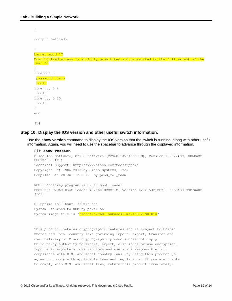
Step 9: Display the current configuration.

The show running-config command displays the entire running configuration, one page at a time. Use the spacebar to advance paging. The commands configured in Steps 1 – 8 are highlighted below.

S1# show running-config Building configuration...

Current configuration : 1409 bytes

!

! Last configuration change at 03:49:17 UTC Mon Mar 1 1993

!

version 15.0

no service pad

service timestamps debug datetime msec

service timestamps log datetime msec

no service password-encryption

!

hostname S1

!

boot-start-marker

boot-end-marker

!

enable secret 4 06YFDUHH61wAE/kLkDq9BGho1QM5EnRtoyr8cHAUg.2

!

no aaa new-model

system mtu routing 1500

!

!

no ip domain-lookup

Lab - Building a Simple Network

© 2013 Cisco and/or its affiliates. All rights reserved. This document is Cisco Public. Page 10 of 14

!

<output omitted>

!

banner motd ^C

Unauthorized access is strictly prohibited and prosecuted to the full extent of the law. ^C

!

line con 0

password cisco

login

line vty 0 4

login

line vty 5 15

login

!

end

S1#

Step 10: Display the IOS version and other useful switch information.

Use the show version command to display the IOS version that the switch is running, along with other useful information. Again, you will need to use the spacebar to advance through the displayed information.

S1# show version Cisco IOS Software, C2960 Software (C2960-LANBASEK9-M), Version 15.0(2)SE, RELEASE SOFTWARE (fc1)

Technical Support: http://www.cisco.com/techsupport

Copyright (c) 1986-2012 by Cisco Systems, Inc.

Compiled Sat 28-Jul-12 00:29 by prod_rel_team

ROM: Bootstrap program is C2960 boot loader

BOOTLDR: C2960 Boot Loader (C2960-HBOOT-M) Version 12.2(53r)SEY3, RELEASE SOFTWARE (fc1)

S1 uptime is 1 hour, 38 minutes

System returned to ROM by power-on

System image file is "flash:/c2960-lanbasek9-mz.150-2.SE.bin"

This product contains cryptographic features and is subject to United

States and local country laws governing import, export, transfer and

use. Delivery of Cisco cryptographic products does not imply

third-party authority to import, export, distribute or use encryption.

Importers, exporters, distributors and users are responsible for

compliance with U.S. and local country laws. By using this product you

agree to comply with applicable laws and regulations. If you are unable

to comply with U.S. and local laws, return this product immediately.

Lab - Building a Simple Network

© 2013 Cisco and/or its affiliates. All rights reserved. This document is Cisco Public. Page 11 of 14

A summary of U.S. laws governing Cisco cryptographic products may be found at:

http://www.cisco.com/wwl/export/crypto/tool/stqrg.html

If you require further assistance please contact us by sending email to

[email protected].

cisco WS-C2960-24TT-L (PowerPC405) processor (revision R0) with 65536K bytes of memory.

Processor board ID FCQ1628Y5LE

Last reset from power-on

1 Virtual Ethernet interface

24 FastEthernet interfaces

2 Gigabit Ethernet interfaces

The password-recovery mechanism is enabled.

64K bytes of flash-simulated non-volatile configuration memory.

Base ethernet MAC Address : 0C:D9:96:E2:3D:00

Motherboard assembly number : 73-12600-06

Power supply part number : 341-0097-03

Motherboard serial number : FCQ16270N5G

Power supply serial number : DCA1616884D

Model revision number : R0

Motherboard revision number : A0

Model number : WS-C2960-24TT-L

System serial number : FCQ1628Y5LE

Top Assembly Part Number : 800-32797-02

Top Assembly Revision Number : A0

Version ID : V11

CLEI Code Number : COM3L00BRF

Hardware Board Revision Number : 0x0A

Switch Ports Model SW Version SW Image

------ ----- ----- ---------- ----------

* 1 26 WS-C2960-24TT-L 15.0(2)SE C2960-LANBASEK9-M

Configuration register is 0xF

S1#

Step 11: Display the status of the connected interfaces on the switch.

To check the status of the connected interfaces, use the show ip interface brief command. Press the spacebar to advance to the end of the list.

S1# show ip interface brief Interface IP-Address OK? Method Status Protocol

Vlan1 unassigned YES unset up up

FastEthernet0/1 unassigned YES unset up up

FastEthernet0/2 unassigned YES unset down down

FastEthernet0/3 unassigned YES unset down down

Lab - Building a Simple Network

© 2013 Cisco and/or its affiliates. All rights reserved. This document is Cisco Public. Page 12 of 14

FastEthernet0/4 unassigned YES unset down down

FastEthernet0/5 unassigned YES unset down down

FastEthernet0/6 unassigned YES unset up up

FastEthernet0/7 unassigned YES unset down down

FastEthernet0/8 unassigned YES unset down down

FastEthernet0/9 unassigned YES unset down down

FastEthernet0/10 unassigned YES unset down down

FastEthernet0/11 unassigned YES unset down down

FastEthernet0/12 unassigned YES unset down down

FastEthernet0/13 unassigned YES unset down down

FastEthernet0/14 unassigned YES unset down down

FastEthernet0/15 unassigned YES unset down down

FastEthernet0/16 unassigned YES unset down down

FastEthernet0/17 unassigned YES unset down down

FastEthernet0/18 unassigned YES unset down down

FastEthernet0/19 unassigned YES unset down down

FastEthernet0/20 unassigned YES unset down down

FastEthernet0/21 unassigned YES unset down down

FastEthernet0/22 unassigned YES unset down down

FastEthernet0/23 unassigned YES unset down down

FastEthernet0/24 unassigned YES unset down down

GigabitEthernet0/1 unassigned YES unset down down

GigabitEthernet0/2 unassigned YES unset down down

S1#

Step 12: Repeat Steps 1 to 12 to configure switch S2.

The only difference for this step is to change the hostname to S2.

Step 13: Record the interface status for the following interfaces.

Interface

S1 S2

Status Protocol Status Protocol

F0/1

F0/6

F0/18

VLAN 1

Why are some FastEthernet ports on the switches are up and others are down?

Lab - Building a Simple Network

© 2013 Cisco and/or its affiliates. All rights reserved. This document is Cisco Public. Page 13 of 14

Reflection

What could prevent a ping from being sent between the PCs?

Note: It may be necessary to disable the PC firewall to ping between PCs.

Appendix A: Initializing and Reloading a Switch

Step 1: Connect to the switch.

Console into the switch and enter privileged EXEC mode.

Switch> enable

Switch#

Step 2: Determine if there have been any virtual local-area networks (VLANs) created.

Use the show flash command to determine if any VLANs have been created on the switch.

Switch# show flash

Directory of flash:/

2 -rwx 1919 Mar 1 1993 00:06:33 +00:00 private-config.text

3 -rwx 1632 Mar 1 1993 00:06:33 +00:00 config.text

4 -rwx 13336 Mar 1 1993 00:06:33 +00:00 multiple-fs

5 -rwx 11607161 Mar 1 1993 02:37:06 +00:00 c2960-lanbasek9-mz.150-2.SE.bin

6 -rwx 616 Mar 1 1993 00:07:13 +00:00 vlan.dat

32514048 bytes total (20886528 bytes free)

Switch#

Step 3: Delete the VLAN file.

a. If the vlan.dat file was found in flash, then delete this file.

Switch# delete vlan.dat Delete filename [vlan.dat]?

You will be prompted to verify the file name. At this point, you can change the file name or just press Enter if you have entered the name correctly.

b. When you are prompted to delete this file, press Enter to confirm the deletion. (Pressing any other key will abort the deletion.)

Delete flash:/vlan.dat? [confirm]

Switch#

Step 4: Erase the startup configuration file.

Use the erase startup-config command to erase the startup configuration file from NVRAM. When you are prompted to remove the configuration file, press Enter to confirm the erase. (Pressing any other key will abort the operation.)

Switch# erase startup-config

Lab - Building a Simple Network

© 2013 Cisco and/or its affiliates. All rights reserved. This document is Cisco Public. Page 14 of 14

Erasing the nvram filesystem will remove all configuration files! Continue? [confirm]

[OK]

Erase of nvram: complete

Switch#

Step 5: Reload the switch.

Reload the switch to remove any old configuration information from memory. When you are prompted to reload the switch, press Enter to proceed with the reload. (Pressing any other key will abort the reload.)

Switch# reload Proceed with reload? [confirm]

Note: You may receive a prompt to save the running configuration prior to reloading the switch. Type no and press Enter. System configuration has been modified. Save? [yes/no]: no

Step 6: Bypass the initial configuration dialog.

After the switch reloads, you should see a prompt to enter the initial configuration dialog. Type no at the prompt and press Enter.

Would you like to enter the initial configuration dialog? [yes/no]: no Switch>


Recommended