Page 1
PRACTICAL # 1
TITLE
THREADING IN LOCK STITCH MACHINE
REQUIREMENTS
Lock stitch machine, sewing thread,
PROCEDURE
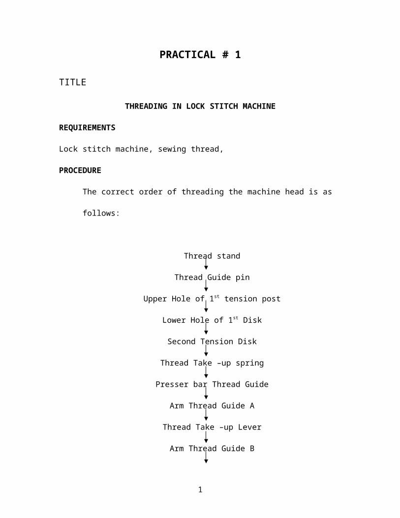
The correct order of threading the machine head is as follows:
Thread stand
Thread Guide pin
Upper Hole of 1st tension post
Lower Hole of 1st Disk
Second Tension Disk
Thread Take –up spring
Presser bar Thread Guide
Arm Thread Guide A
Thread Take –up Lever
Arm Thread Guide B
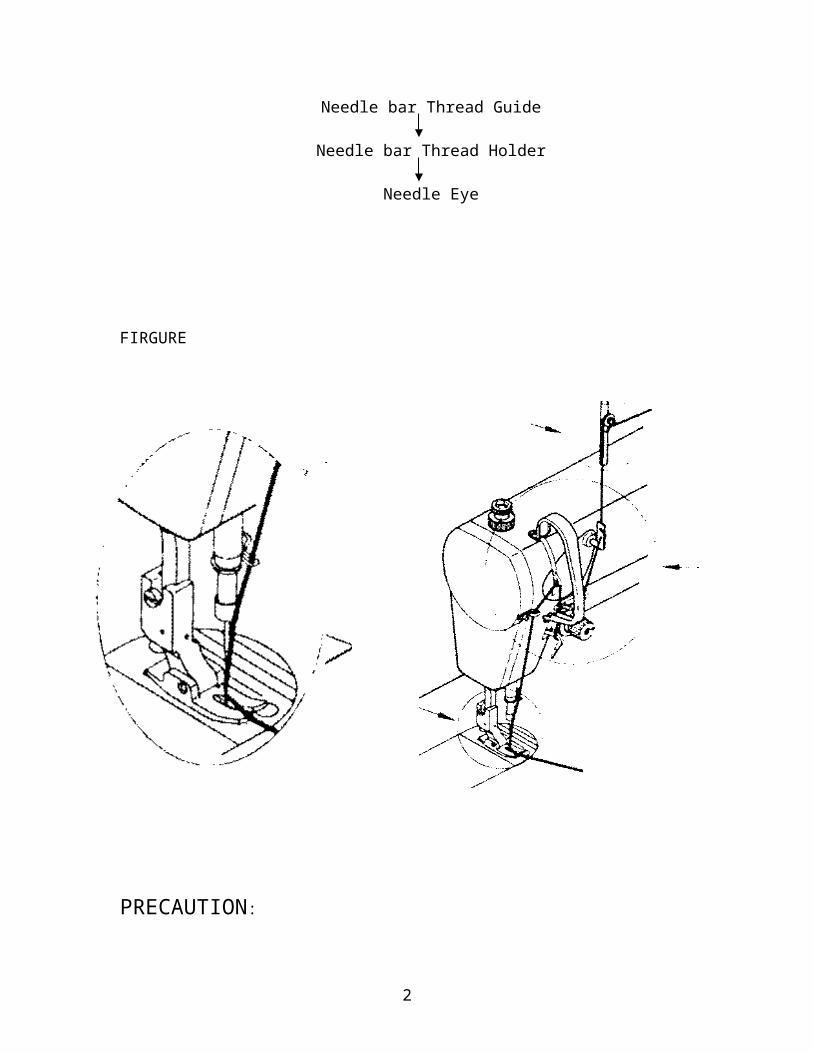
Needle bar Thread Guide
Needle bar Thread Holder
Needle Eye
1
Page 2
FIRGURE
PRECAUTION:
1) Pass the thread to the needle from left to the right
2) Keep the thread of 25-30 mm long behind the needle other wise thread may slip
off the needle at the start of sewing.
2
Page 3
PRACTICAL # 2
TITLE
NEEDLE ATTACHMENT OF LOCK STITCH MACHINE
REQUIREMENTS
Lock stitch machine, sewing needle, sewing thread, needle screw driver
PROCEDURE
The procedures and points which should be considered while attaching the sewing
machine needle are as under.
1) Turn the hand wheel to raise the needle bar to the highest position.
2) Hold a medium-sized screw driver with the right hand, hold lightly the top end of
the Screwdriver with the left hand, and loosen the needle clamp screw.
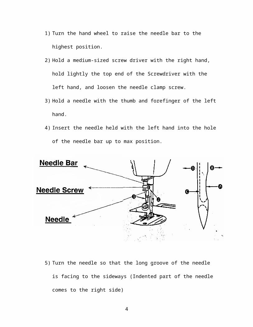
3) Hold a needle with the thumb and forefinger of the left hand.
4) Insert the needle held with the left hand into the hole of the needle bar up to max
position.
3
Page 4
5) Turn the needle so that the long groove of the needle is facing to the sideways
(Indented part of the needle comes to the right side)
6) Support the needle with the left hand, and lightly tighten the needle clamp screw
to such an extent that the needle does not drop down.
7) Detach the left hand from the needle and support the top end of the screwdriver
with the Left hand. Then put force to the screwdriver in the right hand and
securely tighten the needle clamp screw.
4
Page 5
PRACTICAL # 3
TITLE
WIND OF THREAD ON BOBBIN AND THREAD ADJUSTMENT
REQUIREMENTS
Lock Stitch Machine, Bobbin, Sewing Thread.
PROCEDURE
The procedure and points which should be considered to wind the bobbin thread on the
Bobbin is as follows:
1) Insert a bobbin into the thread winding shaft of the bobbin thread winder unit.
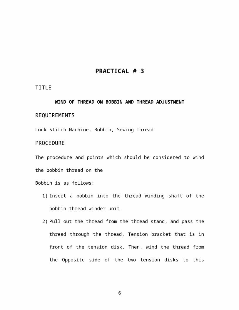
2) Pull out the thread from the thread stand, and pass the thread through the thread.
Tension bracket that is in front of the tension disk. Then, wind the thread from the
Opposite side of the two tension disks to this side. Adjust so that the thread
tension is approximately 15-25 gram.
5
Page 6
3) If thread tension of the tension disk is too low, the thread is loose when the thread
is wound round a bobbin, causing defective stitching or if the thread tension is too
high, the thread is stretched and wound round a bobbin, causing defective
Stitching as well.
4) Draw the thread and wound it round the bobbin from the lower side several times.
5) Tilt the positioning finger, and make the thread winding wheel come in contact
With the belt.
6) Raise the presser foot using the hand lifter lever.
7) Turn ON the power switch, and depress the pedal to operate the sewing machine.
Then, rotate the thread winding wheel to wind the bobbin thread.
8) When a specified amount of the thread is wound round the bobbin, the positioning
Finger comes off, and the thread winding wheel automatically stops.
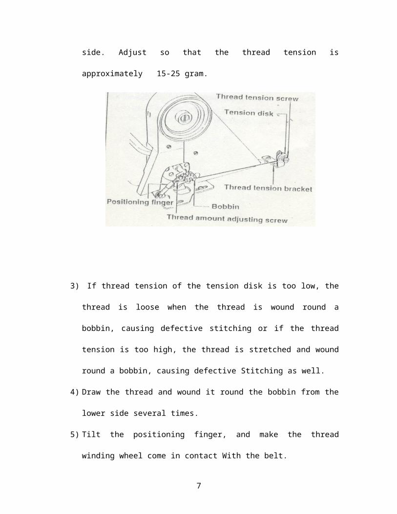
ADJUST THE WINDING CONDITION OF THE BOBBIN THREAD
The way of winding the thread round a bobbin should be made so that the thread is,
uniformly wound round a bobbin as shown.
The points which should be considered are as under:
6
Page 7
a) In case the thread inclines toward the right side of the bobbin - loosen the screw in
the thread tension bracket, and move the tension disk base to the left side.
b) On the contrary, in case it inclines toward the left side of the bobbin - move the
tension disk right side and adjust the position so that the thread is wound
uniformly round the bobbin. In addition, note that an adequate winding amount of
bobbin thread is approximately 80% of the bobbin capacity.
c) In case the amount of thread is small - turn the thread amount adjusting screw to
the right.
d) In case the amount of thread is too large – turn the thread amount adjusting screw
to the left.
7
Page 8
PRACTICAL # 4
TITLE
BOBBIN SETTING INTO THE BOBBIN CASE
REQUIREMENTS
Lock Stitch Machine, Bobbin, Bobbin Case, Sewing Thread,
PROCEDURE
Set the bobbin in accordance with following points.
1) Hold the bobbin that has wound the thread with the right hand so that the thread is
wound to the right.
2) Hold the bobbin case with the left hand, and set the bobbin that is hanging the end
of thread into the bobbin case.
8
Page 9
3) Hold the end of thread coming outside, and pass the thread through the thread slit
Located at the rim of the bobbin case.
4) Pull down the thread and the thread will pass under the tension spring, and then
come out from the notch.
5) Let the thread of 25-30 mm out from the notch.
9
Page 10
PRACTICAL # 5
TITLE
ADJUST THE BOBBIN THREAD TENSION
REQUIREMENTS
Lock Stitch Machine, Bobbin, Bobbin Case, Sewing Thread. Screw driver.
PROCEDURE
The points that should be considered while checking the tension of bobbin thread are:
1) When the bobbin thread is pulled out from the bobbin case, an adequate tension
(Condition of being tense) is necessary.
2) To check it, hold the end of thread, and hang the bobbin case .The adequate
tension is to the extent that the thread is fed out of itself by The weight of bobbin
case when the thread is lightly shaken up and down (in case of Cotton thread, the
thread comes down while the bobbin case does not stop).
3) Refer to the following fig .for bobbin thread tension adjustment.
10
Page 11
CASE -1: BOBBIN THREAD IS LOOSE
When holding the end of the thread, and hanging the bobbin case, the bobbin case
Smoothly comes down.
RECTIFICATION
Turn the thread tension screw in the bobbin case to the right.
CASE-2: BOBBIN CASE DIS TIGHT
The bobbin case does not come down only when the end of the thread is lightly shaken.
RECTIFICATION
Turn the thread tension screw in the bobbin case to the left.
NOTE: The standard thread tension is approximately 15-25 gram when the thread
comes out of the bobbin case.
11
Page 12
PRACTICAL # 6
TITLE
SET THE BOBBIN CASE INTO THE HOOK
REQUIREMENTS
Lock Stitch Machine, Bobbin, Bobbin Case,
PROCEDURE
To set the bobbin case into the hook, perform the work in accordance with the following
Points:
a) Raise the latch of the bobbin case and hold it with the left hand .the bobbin does
not Drop when raising the latch and the bobbin.
b) Insert the bobbin case held with the left hand into the lower side of the machine
bed, Fit it to the shaft of the inner hook, and close the latch of the bobbin case in
the Home position.
12
Page 13
c) At this time ,fully insert the bobbin case into the shaft of the inner hook so that the
Latch securely fits to the groove of the hook.
CAUTION
If the bobbin case has not completely set into the hook, it will cause the troubles
such as
1) Needle breakage
2) Hook breakage
3) Thread entangling
13
Page 14
PRACTICAL # 7
TITLE
ADJUST THE STITCH LENGTH
REQUIREMENTS
Lock Stitch Machine, piece of fabric, sewing thread.
PROCEDURE
Stitch length means the space of the feed of stitch, namely the length of stitch per needle.
Stitch length can be adjusted with the feed adjusting dial and the feed control lever
located under the dial.
14
Page 15
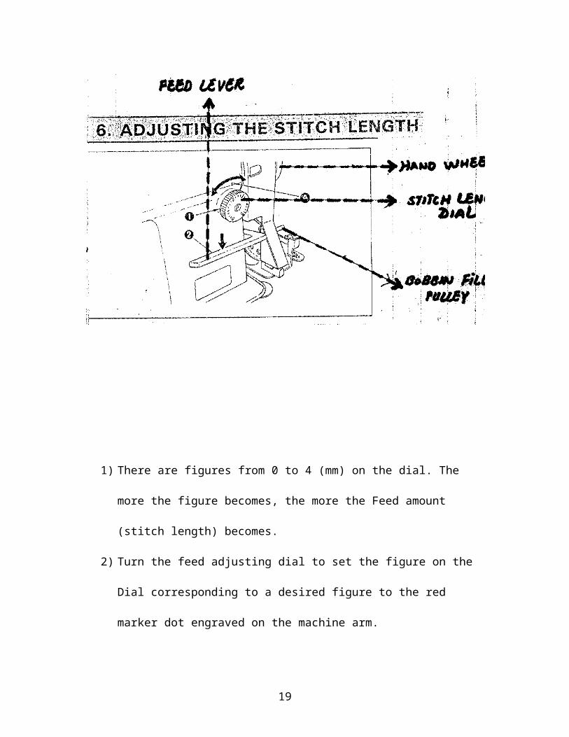
1) There are figures from 0 to 4 (mm) on the dial. The more the figure becomes, the
more the Feed amount (stitch length) becomes.
2) Turn the feed adjusting dial to set the figure on the Dial corresponding to a
desired figure to the red marker dot engraved on the machine arm.
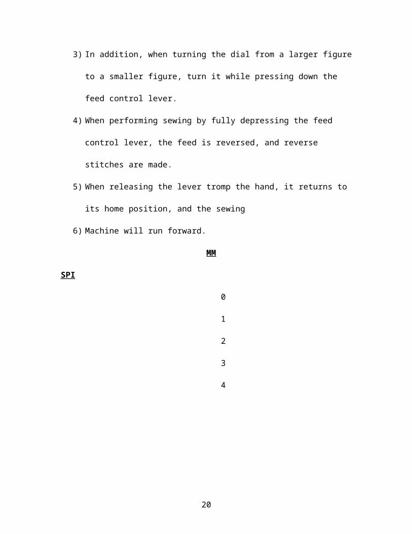
3) In addition, when turning the dial from a larger figure to a smaller figure, turn it
while pressing down the feed control lever.
4) When performing sewing by fully depressing the feed control lever, the feed is
reversed, and reverse stitches are made.
5) When releasing the lever tromp the hand, it returns to its home position, and the
sewing
6) Machine will run forward.
MM SPI
0
1
2
3
4
15
Page 16
PRACTICAL # 8
TITLE
ADJUSTMENT OF THREAD TENSION NUT
REQUIREMENTS
Lock Stitch Machine, Bobbin, Bobbin Case, Sewing Thread. Screw driver.
PROCEDURE
In actual sewing, it is important to make sewing condition suited best to the material
Used
CASE – 1: NEEDLE THREAD TENSION IS TOO LOW
Turn the second thread tension nut clockwise.
CASE – 2: NEEDLE THREAD TENSION IS TOO HIGH
Turn the second thread tension nut counter clockwise.
In addition, turn the first thread tension nut clockwise to reduce the length of thread
remaining in the needle after thread trimming, or counterclockwise to increase the length.
16
Page 17
PRACTICAL # 9
TITLE
ADJUSTMENT OF PRESSER FOOT PRESSURE
REQUIREMENTS
Lock Stitch Machine, Bobbin, presser foot, Sewing Thread. Screw driver.
PROCEDURE
It is necessary to adjust the pressure of the presser foot according to the thickness of the
material.
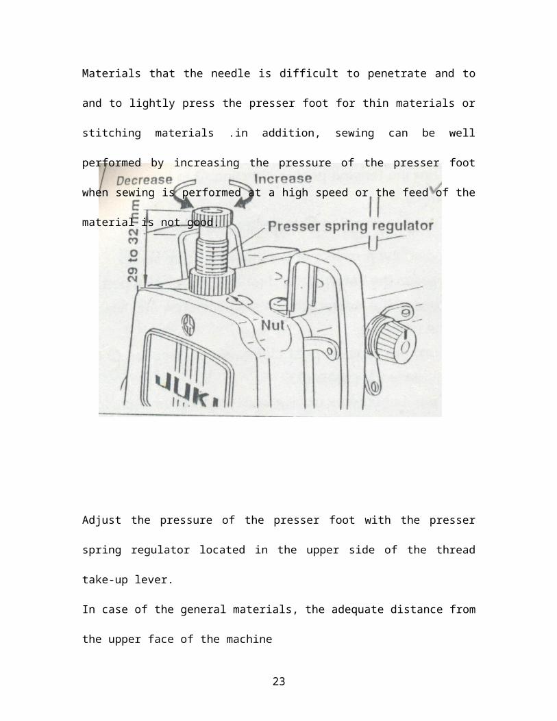
Adjust so as to increase the pressure of the presser foot when sewing thick materials or
Materials that the needle is difficult to penetrate and to and to lightly press the presser
foot for thin materials or stitching materials .in addition, sewing can be well performed
by increasing the pressure of the presser foot when sewing is performed at a high speed
or the feed of the material is not good.
17
Page 18
Adjust the pressure of the presser foot with the presser spring regulator located in the
upper side of the thread take-up lever.
In case of the general materials, the adequate distance from the upper face of the machine
Arm to the top of the regulator is approximately 29-32 mm (pressure of presser foot is 3-
5 kg).Adjust the pressure according to the material as follows:
CASE – 1: TIGHTTEN THE PRESSER SPRING REGULATOR
Screwing the presser spring regulator = presser foot strongly press the material
(Turn clockwise)
CASE – 2: LOOSEN THE PRESSER SPRING REGULATOR
Screw in the presser spring regulator = presser foot lightly presser the material
(Turn counterclockwise) (Pressure of the presser foot decreases)
The height of the presser spring regulator will show the approximate pressure of presser
foot. The references are as follows:
Pressure Height
2 kg 40 mm
3 kg 36.5mm
4 kg 32 mm General pressure of presser foot
5 kg 29 mm
CAUTION:
Adjust the pressure of the presser foot in accordance with the sewing conditions. After
the adjustment, tighten the nut so that the presser spring regulator does not become loose.
18
Page 19
PRACTICAL # 10
TITLE
APPLICATION OF HAND LIFTER IN LOCK STITCH MACHINE
REQUIREMENTS
Lock Stitch Machine, Bobbin, Bobbin Case, Sewing Thread. Screw driver.
PROCEDURE
Hand lifter is used when making idle running of the sewing machine without putting the
material or performing the adjustment & can stop the presser foot at the raised position.
Some of the major points explaining the functions of hand lifter are:
19
Page 20
1) To stop the presser foot at the raised position, turn the hand lifter in the direction
‘A’ (counter clockwise).
2) The presser foot will go up approximately 5.5 mm & stop.
3) The presser foot will go back to its original position when the hand lifter is turned
down in the direction ‘B’ (clockwise).
4) Using the knee lifter the standard presser foot lift of approximately 10 mm and
maximum lift of approximately 13 mm can be obtained.
20
Page 21
PRACTICAL # 11
TITLE
FEED DOGS ADJUSTMENT OF LOCK STITCH MACHINE
REQUIREMENTS
Lock Stitch Machine, Feed Dog, Piece Of Fabric, Sewing Thread. Screw Driver.
PROCEDURE
1) When operating the sewing machine, the material to be sewn advances
continuously since the feed dog located under the presser foot rotates in the shape
of oval and feeds the material forward.
2) If the installing position of the feed dog is too low, the feed becomes defective
when sewing thick materials.
3) If the position of the feed dog kips too high, puckering will result when sewing
light weight materials.
4) As a result, the height of feed dog may be adjusted in accordance with the
thickness of the materials.
21
Page 22
STANDARD HEIGHT
The standard height of the feed dog for genital materials is 0.8 mm from the throat plate
surface and the standard height for thin materials is 0.6 mm from the throat plate surface.
FRONT DOWN
In addition, tilt slightly the feed dog with its front down to prevent the materials such as
knit goods which are easily irregularly stitched or slipped off from becoming such
troubles.
FRONT UP
Tilt slightly the feed dog with its front up to prevent materials such as georgette; satin,
etc, which easily make puckering during stitching.
The good sewing can be obtained by the aforementioned adjustments.
22
Page 23
PRACTICAL # 12
TITLE
ADJUSTMENT OF THREAD TAKE – UP SPRING
REQUIREMENTS
Lock Stitch Machine, Piece Of Fabric, Sewing Thread. Screw Driver.
PROCEDURE
The play or running around of the needle thread is removed by the movement of the
thread Take-up lever. In case such troubles cannot be removed yet, the thread take- up
spring plates a role of compensation.
Make the tension of the thread take-up spring nearly equal to that of the bobbin thread.
However, the stability of thread feed is likely to minutely change in accordance with the
thickness of materials or the stitch length. In this case, adjust the tension and strike of the
thread take-up spring.
When changing the tension of the thread take-up spring
a) Loosen the setscrew and remove the tension post.
b) Loosen the tension post setscrew, and adjust by turning the tension post clockwise
23
Page 24
Or counter –clockwise.
c) Turn the tension post clockwise to increase the tension, and turn counterclockwise
to decrease it.
In addition, to change the stroke of thread take-up spring, loosen the setscrew in the
Tension post socket, and adjust by turning the tension post clockwise or
counterclockwise.
Changing the stroke of the thread take- up spring:
a) Loosen the setscrew in the tension post socket.
b) Turn the tension post indirection A to increase the stroke.
c) Turn it in direction B to decrease the stroke
Changing the pressure of the thread take-up spring:
a) Loosen the setscrew, and remove the tension post.
b) Loosen the thread tension post setscrew and adjust the pressure.
c) Turn the tension post clockwise in direction A to increase the pressure.
d) Turn it counterclockwise in direction B to decrease the pressure.
Changing the moving position of the thread take-up spring:
a) Loosen the setscrew of the tension post socket, and turn the tension post.
(Lower the presser foot and measure the moving position.)
Standard: 6 to 8 mm
Thin materials: 7 to 10 mm
Thick materials: 4 to 6 mm
(For synthetic threads, make the stroke comparatively larger than that of cotton thread).
24
Page 25
PRACTICAL # 13
TITLE
ADJUSTMENT OF THREAD TAKE – UP LEVER
REQUIREMENTS
Lock Stitch Machine, Piece of Fabric, Sewing Thread. Screw Driver.
PROCEDURE
To obtain good stitches, it is important that the difference in the needle thread take-up
Amount of the thread take-up lever and the thread take-up amount of the hook should be
small. Adjustment of the needle thread take-up amount of the thread take-up lever can be
made by moving the arm thread guide clockwise or counterclockwise.
When sewing thick materials, move the thread guide counterclockwise to increase the
Thread take-up amount.
1) When sewing thin materials, move the thread guide clockwise to decrease thread
take-up amount.
25
Page 26
2) When sewing thick materials, move thread guide 1 counterclockwise in direction
A to increase the thread take-up amount.
3) When sewing thin materials, move thread guide clockwise in direction B to
decrease the thread take-up amount.
4) The standard position of thread guide 1 is the position where engraved marker
Line C is aligned with the center of the screw.
26
Page 27
PRACTICAL # 14
TITLE
THREADING IN OVER LOCK MACHINE
REQUIREMENTS
Over Lock Machine, Sewing Thread,
PROCEDURE
The way of threading the machine is indicated in the diagram inside the looper cover.
Pass correctly the threads in the order of lower looper thread and upper looper thread
without mistaking the respective thread paths. If the threads are wrongly passed the
thread paths, it will result in thread breakage or Stitch skipping.
For general purpose over lock sewing machine, there are three threads used;
1) Needle thread
2) Upper looper thread
3) Lower looper thread.
Learn the way of threading while carefully comparing the following explanation with the
following figure:
LOWER LOOPER THREADING
Thread stand
Intermediate thread guide
Thread guide base
Upper looper tension disk
Thread path base
Lower looper thread guide
Lower looper thread take-up lever
Looper thread take-up lever (left)
27
Page 28
Lower looper
UPPER LOOPER THREADINGThread stand
Intermediate thread guide
Thread guide base
Upper looper tension disk
Thread path base
Upper looper thread guide (right)
Upper looper thread guide (middle)
Upper looper thread take-up lever (left)
Upper looper thread guide
Upper looper
NEEDLE THREADING
Thread stand
Intermediate thread guide
Thread guide base
Needle thread tension disk
Needle thread guide
Needle thread take-up lever guide
Needle thread presser guide
Needle
28
Page 29
PRACTICAL # 15
TITLE
ADJUSTMENT OF STITCH LENGTH (OVER LOCK MACHINE)
REQUIREMENTS
Over Lock Machine, Sewing Thread, piece of fabric
PROCEDURE
Align the number desired on the hand wheel with the white engraved point on the belt
cover to adjust the stitch length.
The points and procedures which should be considered while the stitch length
adjustments are as under:
1) Remove the cloth plate cover located on the left side of the sewing machine.
2) Pressing the pushbutton located on the left lower side with the left thumb, turn the
hand wheel. Then, there is response with a click, and the push button enters the
depth.
3) Pressing the button, the number on the hand wheel with the mark as shown in
4) The given figure. In this case ,if the mark is aligned with ‘3’ for example, the
stitch
5) Length is approximately 3 mm (differential feed ratio = 1)
29
Page 30
PRACTICAL # 16
TITLE
ATTACHING THE NEEDLE (OVER LOCK MACHINE)
REQUIREMENTS
Over Lock Machine, Sewing Needle, Needle Screw Driver, Sewing Thread
PROCEDURE
The needle used is the over lock needle; DC X 27.the order of attaching the needle is as
Follows:
1) Turn the hand wheel to the opposite side with the right hand, and bring the needle
Clamp to the highest position.
30
Page 31
2) Loosen the needle clamp screw.
3) Hold the needle with the left hand, and insert the needle in to the needle clamp
Hole with the needle recess facing backward as viewed from the front side of
Sewing machine.
4) Fully insert the needle until it hits the end of the hole, and tighten the needle
Clamp screw with the right hand.
31