Page 1
RPS GROUP OF INSTITUTIONS,BALANA,MOHINDERGARH
DEPTT. OF ELECTRONICS & COMMUNICATION ENGINEERING
LAB MANUAL
OF
ELECTRICAL MACHINE-1
(EE-215-F)
in
ELECTRICAL ENGINEERING
RPS GROUP OF INSTITUTIONS
BALANA,MOHINDERGARH(HARYANA)-123029
Department of Electrical Engineering .
SUPERVISOR : Made By :
Er. Karambir Sheoran Mr.Naveen Chauhan
Asstt.Professor&Head
EE Deptt.
Page 2
RPS GROUP OF INSTITUTIONS,BALANA,MOHINDERGARH
DEPTT. OF ELECTRONICS & COMMUNICATION ENGINEERING
Experiment -1
Aim: TO PERFORM BACK TO BACK TEST ON SINGLE PHASE TRANSFORMERS.
Apparatus: 1) Two transformers, (1- phase, 1 kVA, 220 /115 V,)
2) Two dimmer stats, (0-270 V, 1- phase, 5 A)
3) Voltmeter, (0-300 V),( 0-75 V)
4) Ammeter, (0-2 A), (0-10 A)
5) Wattmeter (0-300 V, 2 A),( 0-75 V, 10 A)
6) Connecting wires
Circuit Diagram:
Page 3
RPS GROUP OF INSTITUTIONS,BALANA,MOHINDERGARH
DEPTT. OF ELECTRONICS & COMMUNICATION ENGINEERING
Procedure: 1) Make the connections as shown in circuit diagram.
2) Keep secondary windings.
3) Switch ON the supply and check the correctness of polarities of the two
transformers. If V2 = 0 then polarities of connected transformers are correct i.e.
connections are back to back and emf induced in secondaries are in phase
opposition but if V2 = 2xKxV1, then secondary emfs are in phase, in that case
change the polarities of any one secondary winding.
4) Note down the readings of V1, I1 and W1
5) Now close switch S2, S3 and increase dimmerstat output voltage gradually so that full
load current flows through deviate from their earlier readings.
6) Note down V2 , I2 and W2. While doing so , the values shown by V1, I1 and W1 should
not switches S2 & S3 open and the dimmerstats at zero position.
Observation Table:
Calculations:
Iron loss per transformer Wi = W1 / 2
Copper loss per transformer Wcu = W2 / 2
Output Power
% Efficiency = ------------------------------ x 100
Output Power + Losses kVA x Cos _
% _ = ------------------------------------------------ x 100
kVA x Cos _ + Iron loss + Cu. Loss
With the help of above equation, calculate efficiency at
1. Full load, UPF
2. Half full load and 0.8 p.f. lagging.
Results: It is found that,
i) % Efficiency at F.L. & unity power factor =
ii) % Efficiency at half full load & 0.8 power factor (lag.) =
Viva Questions:
1. What is the condition to be satisfied by the two transformers to be tested using this
method?
2. What is the main advantage of this test?
3. Other than losses and efficiency, what else can be determined from this test?
4. How are the full load conditions simulated?
5. How are the losses separated?
Page 4
RPS GROUP OF INSTITUTIONS,BALANA,MOHINDERGARH
DEPTT. OF ELECTRONICS & COMMUNICATION ENGINEERING
Experiment -2
D.C SHUNT MOTOR
OBJECT:
To study the variation of speed of a. d. c. shunt motor.
i) With armature voltage under constant field excitation, and
ii) With field excitation under constant armature voltage.
CIRCUIT DIAGRAM:
Fig. 1 Speed Control of D.C. Shunt Motor
PROCEDURE:
i) Connect the circuit as shown in figure – 1.
ii) Start the motor with maximum resistance in the armature circuit and minimum
resistance in the field circuit.
iii) Bring the motor to the rated speed, first by decreasing the resistance in the armature
circuit and then by increasing the resistance in the field circuit.
iv) Vary the resistance in the field circuit and take readings of speed and field current,
keeping the armature voltage constant at a particular value.
v) Change armature voltage to another value and repeat the procedure given in – (iv)
vi) Then change the resistance in the armature circuit and take reading of speed and
armature voltage, keeping the field current constant at a particular value.
vii) Change the field current to another value, repeat the procedure given in (vi).
viii) Take three sets of readings for each method of variation.
OBSERVATION :
Table I: Variation of speed with field excitation
Page 5
RPS GROUP OF INSTITUTIONS,BALANA,MOHINDERGARH
DEPTT. OF ELECTRONICS & COMMUNICATION ENGINEERING
S.NO Field current(A) Speed(rpm) Constant Armature
Voltage (V)
Table II : Variation of speed with armature voltage.
Sl.
No.
Armature voltage (V) Speed(rpm
)
Constant field Current (A)
RESULTS :
i) Plot speed against field current for different sets of constant armature
voltage on a graph paper.
ii) Plot speed against armature voltage for different sets of constant field
current on another graph paper.
DISCUSSION :
i) Discuss and explain about the nature of the plots with relevant equations.
ii) Discuss about the limitations and merits of the two methods of speed control.
iii) Why do you keep the resistance in the armature circuit at a maximum, and
resistance in the field circuit a minimum at start?
iv) What will happen when the field circuit gets opened, while the machine is running
v) At steady state condition, draw an equivalent circuit diagram for the DC shunt
Motor and express it with a mathematical model.
2.5
Page 6
RPS GROUP OF INSTITUTIONS,BALANA,MOHINDERGARH
DEPTT. OF ELECTRONICS & COMMUNICATION ENGINEERING
Experiment -3
SWINBURN’S TEST
AIM To predetermine the efficiency o the D.C. machine as
(i) Motor
(ii) Generator
APPARATUS REQUIRED:-
Sl.No. Name of the apparatus Range Type Quantity
1. Ammeter (0 -10A) MC 1
2. Ammeter (0 - 2 A) MC 1
3. Voltmeter (0 - 300 V) MC 1
4. Rheostat 200, 2AΩ - 1
5. Tachometer (0 -
10000rpm) Analog 1
PROCEDURE
The connections are made as per the circuit diagram.
The DPST switch is closed.
The motor is started using three point starter.
The field rheostat of the motor is adjusted to bring the motor speed to the rated
value.
The no load current, voltage and shunt field current are noted.
PRECAUTION
The field rheostat should be kept at minimum resistance position.
There should be no load at the time of starting the experiment.
TABULAR COLOUMN
Page 7
RPS GROUP OF INSTITUTIONS,BALANA,MOHINDERGARH
DEPTT. OF ELECTRONICS & COMMUNICATION ENGINEERING
Sl. No. Voltage, V (volts) Field current, Ir
(A)
No load current, I0
(A)
For generator
Sl.
No.
Voltage
(volts)
Load
Current,
IL
(A)
Ia = IL
+If
(A)
Ia2 Ra
Total
Loss
(watts)
Input
Power
(watts)
Output
Power
(watts)
Efficiency
%
For motor
Sl.
No.
Voltage
(volts)
Load
Current,
IL
(A)
Ia =
IL +If
(A)
Ia2 Ra
Total
Loss
(watts)
Input
Power
(watts)
Output
Power
(watts)
Efficiency
%
Page 8
RPS GROUP OF INSTITUTIONS,BALANA,MOHINDERGARH
DEPTT. OF ELECTRONICS & COMMUNICATION ENGINEERING
RESULT
Thus the efficiency of the DC machine has been predetermined and characteristic
were drawn.
Page 9
RPS GROUP OF INSTITUTIONS,BALANA,MOHINDERGARH
DEPTT. OF ELECTRONICS & COMMUNICATION ENGINEERING
Experiment -4
AIM To draw the open circuit characteristics of self excited D.C. shunt generator
APPARATUS REQUIRED:-
Sl. No. Name of the
apparatus Range Type Quantity
1. Ammeter (0 - 20A) MC 1
2. Ammeter (0 - 2A) MC 1
3. Voltmeter (0 - 300V) MC 1
4. Rheostat 200 Ω, 2A - 1
5. Tachometer (0 -
10000rpm) Analog 1
Page 10
RPS GROUP OF INSTITUTIONS,BALANA,MOHINDERGARH
DEPTT. OF ELECTRONICS & COMMUNICATION ENGINEERING
Open Circuit Characteristics:-
PROCEDURE
The connections are made as per the circuit diagram.
The DPST switch is closed.
The motor is started using three point starters.
By varying the field rheostat of the motor, the speed of the motor, is adjusted to the
rated speed of the generator.
The initial voltage due to residual magnetism in noted & The SPST switch should be
closed.
The field rheostat of the generator is varied in steps.
In each step the ammeter and voltmeter readings are noted.
PRECAUTION
All the switches are kept open initially.
The motor field rheostat is kept at minimum resistance position.
The generator field rheostat is kept at maximum resistance position.
The SPST should be kept open at the time of starting to find the residual voltage.
TABULAR COLOUMN
Sl. No. Field current,
If Amperes
Generated
EMF,
Eg volts
1.
2.
3.
4.
5.
6.
Page 11
RPS GROUP OF INSTITUTIONS,BALANA,MOHINDERGARH
DEPTT. OF ELECTRONICS & COMMUNICATION ENGINEERING
Load test
PROCEDURE
The connections are given as per the circuit diagram.
The DPST of the motor side is closed.
The motor is started using the 3- point starter.
By varying the field rheostat of the motor, the speed of the motor is adjusted to the
rated speed of the generator.
The DPST switch of the generator side is closed.
The load on the generator is applied in steps.
At each step of loading the meter readings are noted.
The procedure is repeated till the ammeter reads the rated current of the generator.
PRECAUTION
Page 12
RPS GROUP OF INSTITUTIONS,BALANA,MOHINDERGARH
DEPTT. OF ELECTRONICS & COMMUNICATION ENGINEERING
All the switches are kept open initially.
The motor field rheostat is kept at minimum resistance position.
The generator field rheostat is kept at maximum resistance position.
There should not be any load on the generator when start and stop the motor.
TABULAR COLOUMN FOR LOAD TEST
Sl.
No.
Voltage,
V
(Volts)
Current,
IL
(Amperes)
Field
current, If
(Amperes)
Armature
Current,
Ia
(Amperes)
Generated
EMF, Eg
(Volts)
MODEL CALCULATION:-
Armature current, Ia = IL = If
Generated EMF, Eg = (V + Ia Ra)
Page 13
RPS GROUP OF INSTITUTIONS,BALANA,MOHINDERGARH
DEPTT. OF ELECTRONICS & COMMUNICATION ENGINEERING
Experiment -5
INDUCTION MOTOR
1. OBJECT: i) To study the constructional features of three phase induction motor.
ii) To plot torque Vs slip characteristic of the motor over the operating range.
iii) To plot power factor and efficiency of the motor against the shaft load.
2. CIRCUIT DIAGRAM :
Figure 1.
2.1 Procedure:
Following steps are to be followed to carry out the experiment.
1. Choose the appropriate ranges of various meters and connect the circuit as shown
in Figure 1
2. Keep S1, S
3 and S
4 open but S
2 closed.
3. Keeps the autotransformer setting to get zero output voltage.
4. Now close S1 and gradually increase the applied voltage to the rated value of the
induction machine.
5. The motor starts running at no load. Open the switch S2 and note down all the
readings as per Table 1. below.
6. Keep Rf at its maximum value and close the switch S3 to energise the field winding
of the generator.
7. Adjust Rf such that rated voltage is generated across the armature of the D.C.
generator, V2 indicates the generated voltage.
8. Ensuring that all the switches of the loading rheostat are open, close the switch S4.
Page 14
RPS GROUP OF INSTITUTIONS,BALANA,MOHINDERGARH
DEPTT. OF ELECTRONICS & COMMUNICATION ENGINEERING
9. Now start closing the switches of the loading rheostat in steps and record all the
meter readings, including speed at the appropriate places in table. Note that the
rated current of the induction motor should not be exceeded while closing the
loading rheostat switches.
2.2 Computation & plots
1. Output power of generator = Pe output
= V2A
2
2. Shaft power of the induction motor, Psh
= V2A
2 + Po, where Po is the constant
rotational loss comprising of the frictional loss and core loss of the D.C.
generator. (Note: Psh ignores small amount of D.C. armature copper loss)
3. Estimated shaft torque of the induction motor 602shshPTnrπ= where nr is in
rpm.
4. Calculated slip rsnnsn−
5. Total input power to the induction motor, Pin
= 3W.
6. Operating power factor of the induction motor, 113inPCosVAθ=
7. Estimated efficiency of the induction motor, inshPPη=
Table 1
Draw the following graphs:
1. Torque vs. slip.
2. Power factor vs slip.
3. Efficiency vs. slip 2.15
Supply frequency = 50 Hz Recorded values Calculated values
Sl. No. V1
(V)
A1
(A)
V2
(V)
A2
(A)
W
(W)
Spe
ed
(rp
m)
Slip
%
Tsh
Cos
θ
η
m
1.
2.
3.
4.
Page 15
RPS GROUP OF INSTITUTIONS,BALANA,MOHINDERGARH
DEPTT. OF ELECTRONICS & COMMUNICATION ENGINEERING
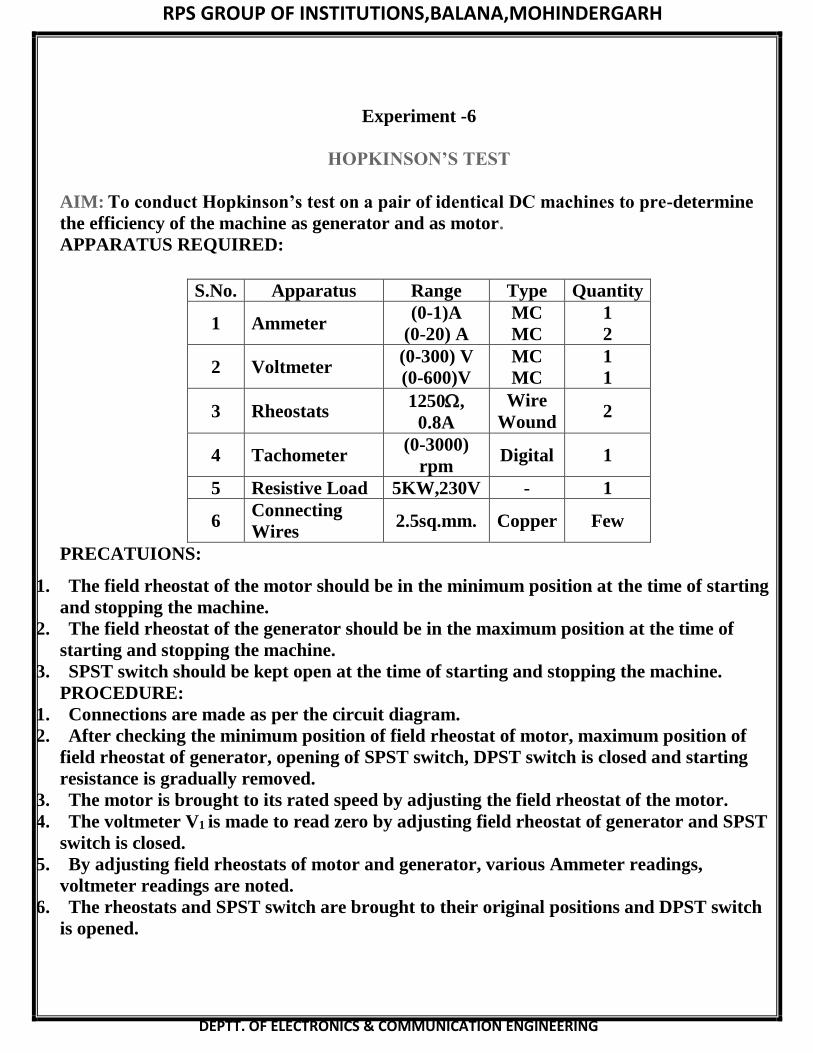
Experiment -6
HOPKINSON’S TEST
AIM: To conduct Hopkinson’s test on a pair of identical DC machines to pre-determine
the efficiency of the machine as generator and as motor.
APPARATUS REQUIRED:
S.No. Apparatus Range Type Quantity
1 Ammeter (0-1)A
(0-20) A
MC
MC
1
2
2 Voltmeter (0-300) V
(0-600)V
MC
MC
1
1
3 Rheostats 1250,
0.8A
Wire
Wound 2
4 Tachometer (0-3000)
rpm Digital 1
5 Resistive Load 5KW,230V - 1
6 Connecting
Wires 2.5sq.mm. Copper Few
PRECATUIONS:
1. The field rheostat of the motor should be in the minimum position at the time of starting
and stopping the machine.
2. The field rheostat of the generator should be in the maximum position at the time of
starting and stopping the machine.
3. SPST switch should be kept open at the time of starting and stopping the machine.
PROCEDURE:
1. Connections are made as per the circuit diagram.
2. After checking the minimum position of field rheostat of motor, maximum position of
field rheostat of generator, opening of SPST switch, DPST switch is closed and starting
resistance is gradually removed.
3. The motor is brought to its rated speed by adjusting the field rheostat of the motor.
4. The voltmeter V1 is made to read zero by adjusting field rheostat of generator and SPST
switch is closed.
5. By adjusting field rheostats of motor and generator, various Ammeter readings,
voltmeter readings are noted.
6. The rheostats and SPST switch are brought to their original positions and DPST switch
is opened.
Page 16
RPS GROUP OF INSTITUTIONS,BALANA,MOHINDERGARH
DEPTT. OF ELECTRONICS & COMMUNICATION ENGINEERING
TABULAR COLUMN: AS MOTOR:
S.No.
Suppl
y
Volta
ge
V(Vo
lts)
I1
(Am
ps)
I2
(Am
ps)
I3
(Am
ps)
I4
(Am
ps)
I1 +
I2
(Am
ps)
Motor
Armat
ure
Cu
Loss
W
(watts
)
Generat
or
Armatu
re
Cu Loss
W(watts
)
Tota
l
Stra
y
losse
s
W
(wat
ts)
Stray
Loss
Per M/c
w/2 (watts)
Page 17
RPS GROUP OF INSTITUTIONS,BALANA,MOHINDERGARH
DEPTT. OF ELECTRONICS & COMMUNICATION ENGINEERING
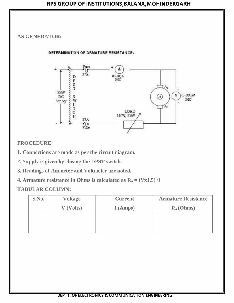
AS GENERATOR:
PROCEDURE:
1. Connections are made as per the circuit diagram.
2. Supply is given by closing the DPST switch.
3. Readings of Ammeter and Voltmeter are noted.
4. Armature resistance in Ohms is calculated as Ra = (Vx1.5) /I
TABULAR COLUMN:
S.No. Voltage
V (Volts)
Current
I (Amps)
Armature Resistance
Ra (Ohms)
Page 18
RPS GROUP OF INSTITUTIONS,BALANA,MOHINDERGARH
DEPTT. OF ELECTRONICS & COMMUNICATION ENGINEERING
FORMULAE:
Input Power = VI1 watts
Motor armature cu loss = (I1+ I2)2 Ra watts
Generator armature cu loss = I22 Ra watts
Total Stray losses W = V I1 - (I1+I2)2 Ra + I22 Ra watts.
Stray loss per machine = W/2 watts.
AS MOTOR:
Input Power = Armature input + Shunt field input
= (I1+ I2) V + I3V = (I1+I2+I3) V
Total Losses = Armature Cu loss + Field loss + stray loss
= (I1 + I2)2 Ra + VI3 + W/2 watts
Input power – Total Losses
Efficiency % = ------------------------------------- x 100%
Input Power
AS GENERATOR:Output Power = VI2 watts
Total Losses = Armature Cu loss+ Field Loss + Stray loss
= I22 Ra + VI4 + W/2 watts
Output power
Efficiency % = -------------------------------------- x 100%
Output Power+ Total Losses
RESULT:
Thus Hopkinson’s test is conducted on a pair of identical DC machines the efficiency of
the machine as generator and as motor are pre-determined
Page 19
RPS GROUP OF INSTITUTIONS,BALANA,MOHINDERGARH
DEPTT. OF ELECTRONICS & COMMUNICATION ENGINEERING
Experiment -7
LOAD TEST ON DC SHUNT MOTOR
AIM: To conduct a load test on DC shunt motor and to find its efficiency
APPARATUS REQUIRED:
S.No. Apparatus Range Type Quantity
1 Ammeter (0-20)A MC 1
2 Voltmeter (0-300)V MC 1
4 Tachometer (0-1500) rpm Digital 1
5 Connecting Wires 2.5sq.mm. Copper Few
PRECAUTIONS:
1. DC shunt motor should be started and stopped under no load condition.
2. Field rheostat should be kept in the minimum position.
3. Brake drum should be cooled with water when it is under load.
PROCEDURE:
1. Connections are made as per the circuit diagram. Circumference of the Brake drum =
cm.
2 After checking the no load condition, and minimum field rheostat position, DPST switch
is closed
and starter resistance is gradually removed.
3 The motor is brought to its rated speed by adjusting the field rheostat.
4 Ammeter, Voltmeter readings, speed and spring balance readings are noted under no
load
condition.
5 The load is then added to the motor gradually and for each load, voltmeter, ammeter,
spring
balance readings and speed of the motor are noted.
The motor is then brought to no load condition and field rheostat to minimum position,
then DPST switchis opened
FORMULAE:
Circumference
R = -------------------
Output Power Pm = ------------ Watts60
Output Power
-------------------- x 100%Input Power
Page 20
RPS GROUP OF INSTITUTIONS,BALANA,MOHINDERGARH
DEPTT. OF ELECTRONICS & COMMUNICATION ENGINEERING
Page 21
RPS GROUP OF INSTITUTIONS,BALANA,MOHINDERGARH
DEPTT. OF ELECTRONICS & COMMUNICATION ENGINEERING
Experiment -8
V AND INVERTED V CURVES OF THREE PHASE SYNCHRONOUS MOTOR
AIM:To draw the V-Curves and inverted v-curves of the given three phase synchronous
motor by constant output.
APPARATUS REQUIRED:
S. No. Name of the Equipment Range Type Qty
PRECAUTIONS:
1. The field rheostat of motor should be in minimum resistance position initially.
2. The field rheostat of alternator should be in maximum resistance position while
starting.
PROCEDURE:
OC Test:
1. Connections are made as per the circuit diagram
2. DPST – I is closed and the motor is started using a 3 point starter
3. The field rheostat of motor is adjusted to give rated speed of alternator.
4. DPST – 2 is closed and the field rheostat of alternator is adjusted to get
various voltages and corresponding field currents are noted. This procedure is
repeated up to rated field current.
SC Test:
1. Connections are made as per the circuit diagram.
2. DPST – I is closed and the motor is started using a 3 point starter.
3. The field rheostat of motor is adjusted to get rated speed of the alternator.
4. The field rheostat of alternator is adjusted to get rated current in the armature
of alternator.
5. This value of Isc and the corresponding If are noted.
Page 22
RPS GROUP OF INSTITUTIONS,BALANA,MOHINDERGARH
DEPTT. OF ELECTRONICS & COMMUNICATION ENGINEERING
6. The field rheostat of alternator is brought back to maximum resistance
Position and the field rheostat of the motor is brought back to minimumResistance
position.
7. Open the DPSTS.
Determination of Ra:
1. Connections are made as per the circuit diagram
2. DPSTS is closed and the rheostat is adjusted
3. For various values of voltages the value of current is noted
4. The rheostat is brought back to maximum position
Open Circuit Test
S.No. No load voltage V0 No Load Field Current
Short Circuit Test:
S.No. Rated I(A) If (A)
FORMULAE USED:
Ra= Rdc* 1.3
Zs= Vph/Isc
2-Ra
2)
-1(Xs/Ra)
SYNCHRONOUS REACTANCE:
OCC and SC characteristic are drawn as shown. The field current OA gives the rated
voltage per phase RV.
The same field current RA given as armature current OB on short circuit.
Therefore Synchronous Impedance, ZS=OV/OB
Therefore Synchronous Reactance, XS=√ZS
2 –RS
2
CONSTANT INPUT POWER LINE:
Let P be the constant total input to the synchronous motor. Therefore constant input
power per phase equals
P/3. Therefore Vph*Iph*cosΦ=P/3
Iph* cosΦ=P/3Vph
Since P & V are constant Iph*cosΦ is also a constant.
The reference OV1 is drawn to represent V as shown in the figure.
Page 23
RPS GROUP OF INSTITUTIONS,BALANA,MOHINDERGARH
DEPTT. OF ELECTRONICS & COMMUNICATION ENGINEERING
The vector OR is equal to Vph/ZS is drawn lagging OV1 by an angle
MODEL GRAPH:
V Curves.
Where α = tan-
perpendicular to the reference
vector OV1. This line represents the constant input power line.
CONSTANT EXCITATION CIRCLES:
OR=Vph/Zph represents 100% excitation with R as centre and OR as radius a circle is
drawn. This circle is known as 100% excitation circle. Similarly constant excitation circle
cuts the constant input power line at T.
Page 24
RPS GROUP OF INSTITUTIONS,BALANA,MOHINDERGARH
DEPTT. OF ELECTRONICS & COMMUNICATION ENGINEERING
RESULT: Thus V-curves and inverted V curves of synchronous motor were drawn.
Page 25
RPS GROUP OF INSTITUTIONS,BALANA,MOHINDERGARH
DEPTT. OF ELECTRONICS & COMMUNICATION ENGINEERING
Experiment -9
SYUDY OF DC MOTOR STARTERS
AIM: To study about the DC motor starter.
TWO POINT STARTER:
A two point starter is used for switching a series motor which has the problem of over
spreading due to loss at
the load from the shaft. Here for starting the motor, the control on in moved clockwise
from its position against
the spring tension. The control arm is held in the ‘ON’ position by an electromagnet. This
held on electro magnet connected in series with the armature circuit. If the motor losses it
load current and hence the strength of the electromagnet also decreases. The control arm
return to the DFF position due to a spring tension, thus the preventing motor from over
spreading the starter which are connected with the supply
and motor terminals.
THREE POINT STARTER:
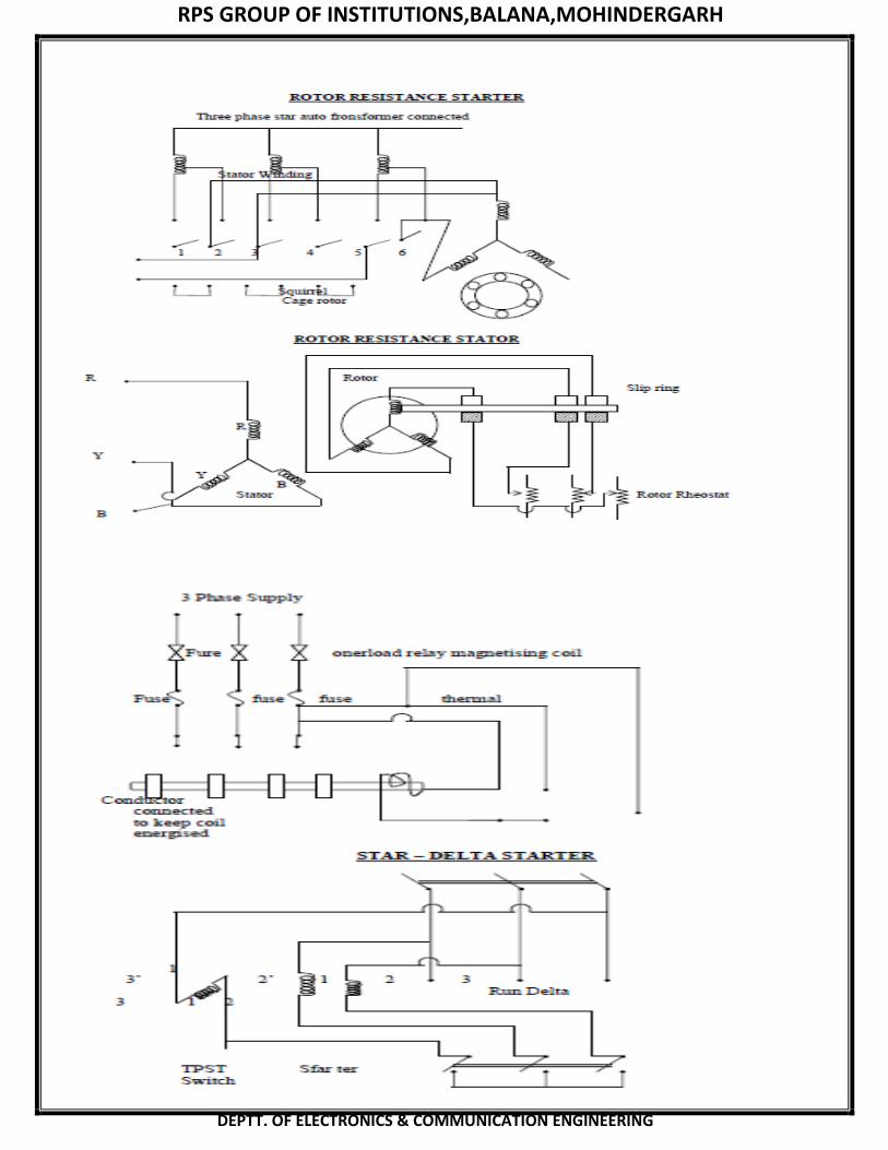
THREE PHASE INDUCTION MOTOR STARTERS:
1. AUTO TRANSFORMERS:
It is also known as autotransformers or compensator. It consists of an autotransformers
with necessaryswitches or three phase transformers reduced voltage is applied to the
motor when the motor pick up 80%. So,
Page 26
RPS GROUP OF INSTITUTIONS,BALANA,MOHINDERGARH
DEPTT. OF ELECTRONICS & COMMUNICATION ENGINEERING
that the transformer is out-out and full voltage is given to the motor most of the
autotransformer are provided
with 3 sets of tops so as to reduce the voltage to 85, 60 up to 50% of the line voltage. Again
the autotransformer
starter may also be provided with stop overload protection and interlocks. The completer
scheme of the starter
also included.
(a) Interlocks to ensure reduced voltage starting.
(b) Protection against over load etc..,
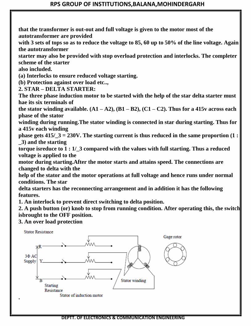
2. STAR – DELTA STARTER:
The three phase induction motor to be started with the help of the star delta starter must
hae its six terminals of
the stator winding available. (A1 – A2), (B1 – B2), (C1 – C2). Thus for a 415v across each
phase of the stator
winding during running.The stator winding is connected in star during starting. Thus for
a 415v each winding
phase gets 415/_3 = 230V. The starting current is thus reduced in the same proportion (1 :
_3) and the starting
torque isreduce to 1 : 1/_3 compared with the values with full starting. Thus a reduced
voltage is applied to the
motor during starting.After the motor starts and attains speed. The connections are
changed to delta with the
help of the stator and the motor operations at full voltage and hence runs under normal
conditions. The star
delta starters has the reconnecting arrangement and in addition it has the following
features.
1. An interlock to prevent direct switching to delta position.
2. A push button (or) knob to stop from running condition. After operating this, the switch
isbrought to the OFF position.
3. An over load protection
.
Page 27
RPS GROUP OF INSTITUTIONS,BALANA,MOHINDERGARH
DEPTT. OF ELECTRONICS & COMMUNICATION ENGINEERING
.This method is used in the case of the motor which one built t run normally with a delta
connected starter
winding. It consists of two way switch connect the motor in star for starting and then delta
for normal running. The star connected applied voltage by a factor of 1/_3 and hence the
torque developed
because 1/_3 of that of which would have been developed if the motor war directly
connected in the delta. The three types of star delta starters are:
1. Hand Operated
2. Semi Automatic
3. Fully Automatic
3. DIRECT ON LINE STARTER (or) D.O.L. STARTER:
When fully voltage is supplied across the starters of indction motor, lot of current in
drawn by the winding. This is because at the time of starting the induction motor are
started using direct on line starter on heavy starting curent will flow through the winding
such as heavy starting current of short duration may not cause to the motor. Since the
construction of induction motor are rugged. More over it takes time for temperature rise
to endanger the utilization of motor windings. But this heavy impression current will
cause large voltage drop with the linear during the period of motor A direct alternate
method at starting of induction motor is application up to starting of induction motor. The
ON push button is pressed coil A becomes energized and if open contacts are closed when
OFF button push button is pressed in a will get energized and main contacts of the
conductor open when the motor starts, in case of overload on the motor the contact of
over load may be opened and sub sequently the motor will stop. In case of over load the
overload relay also opens the circuit of the coil and the contactor opens. In case of a
supply failure while the motor is running, the coil is deenergized and the motor is isolated
from the supply lines. After the supply is resumed the operator has to operate the start
push button for running the motor
Page 28
RPS GROUP OF INSTITUTIONS,BALANA,MOHINDERGARH
DEPTT. OF ELECTRONICS & COMMUNICATION ENGINEERING
Page 29
RPS GROUP OF INSTITUTIONS,BALANA,MOHINDERGARH
DEPTT. OF ELECTRONICS & COMMUNICATION ENGINEERING
If is used for starting a shunt on compound motor will at the load held on electromagnet is
connected in series with the shunt field coil. In case at disconnection in the field circuit due
to the internal feature (or) field rheostat failure. The control arm will retain to its OFF
position due to spring tension. It is necessary because the shunt motor will over speed is it
losses the field ecitation. The starter also retains to the OFF position in case of low supply
using no volt release over load protection for the motor can be interrupted by connecting
another electromagnetic coils. This coil falls on iron piece upwards within short circuit
the coil ab hold down electromagnet. The electromagnet gets reenergized and three force
the starter arm return to ‘OFF’ position. Thus protecting the motor against overload. If
should be noted that (L, F, A) are three terminals of a three point starter use at a grass
strip as shown in fig enables can’t of the field circuit directly with the supply is stead of
via the starter resistance.
FOUR POINT STARTER:
When compared tot three point starter it will be noticed that one important change has
been taken at the shunt field circuit and has been connected directly access the time
through a protecting resistance. When the arm touches stud no. I the line current divides
into three parts.
1. One part posses through the starting resistance Rs series field and motor armature.
2. The second part posses through the shunt field and its field.It should be particularly
noted that this
arrangement any change at current is the shunt field doesn’t offer the current passing
through the motion coil. It means the electromagnet full excited by the hold on coil.
DIRECT ON LINE STARTER (or) D.O.L. STARTER:
When fully voltage is supplied across the starters of indction motor, lot of current in
drawn by the winding. This is because at the time of starting the induction motor are
started using direct on line starter on heavy starting curent will flow through the winding
such as heavy starting current of short duration may not cause to the motor. Since the
construction of induction motor are rugged. More over it takes time for temperature rise
to endanger the utilization of motor windings. But this heavy impression current will
cause large voltage drop with the linear during the period of motor A direct alternate
method at starting of induction motor is application up to starting of induction motor. The
ON push button is pressed coil A becomes energized and if open contacts are closed when
OFF button push button is pressed in a will get energized and main contacts of the
conductor open when the motor starts, in case of overload on the motor the contact of
over load may be opened and sub sequently the motor will stop. In case of over load the
overload relay also opens the circuit of the coil and the contactor opens. In case of a
supply failure while the motor is running, the coil is deenergized and the motor is isolated
from the supply lines. After the supply is resumed the operator has to operate the start
push button for running the motor
Page 30
RPS GROUP OF INSTITUTIONS,BALANA,MOHINDERGARH
DEPTT. OF ELECTRONICS & COMMUNICATION ENGINEERING
Page 31
RPS GROUP OF INSTITUTIONS,BALANA,MOHINDERGARH
DEPTT. OF ELECTRONICS & COMMUNICATION ENGINEERING
RESULT:
Thus the DC and AC Motor starters were studied


![Electrical Machines Lab II Manual[1]](https://static.documents.pub/doc/80x56/553d18505503467a438b4d47/electrical-machines-lab-ii-manual1.jpg)


