Cite this: Lab Chip, 2013, 13, 2714 Chemiluminescence detector based on a single planar transparent digital microfluidic device3 Received 6th February 2013, Accepted 12th April 2013 DOI: 10.1039/c3lc50170a www.rsc.org/loc Xiangyu Zeng, a Kaidi Zhang, a Jian Pan, a Guoping Chen, a Ai-Qun Liu, b Shih-Kang Fan c and Jia Zhou* a We report on a compact and portable prototype of chemiluminescence detector based on a single planar single polar transparent electrowetting-on-dielectrics (EWOD) device. The coupling ground model was proposed to build the EWOD device, which could be driven under a single polar voltage. Such a design not only simplified the chip construction and control circuit, but also had the potential for the ball-like droplet to focus the fluorescence and enhance the detection sensitivity. Simulations and experiments both confirmed that the greater the contact angle, the stronger the detected optical signal, and thus the higher the sensitivity. The sensitivity of the prototype detector to H 2 O 2 was 5.45 mV (mmol L 21 ) 21 and the detection limit was 0.01 mmol L 21 when the contact angle of the EWOD surface was 120u. To further increase the sensitivity and decrease the detection limit, the contact angle of the EWOD device could be increased and the dark current of the photomultiplier decreased. The prototype shows potential applications as highly sensitive, cost effective and portable immuno-detectors, especially as a blood glucose monitor. 1. Introduction In recent years, biosensors have developed rapidly and found wide applications in fields such as food, industry, environ- ment, clinical diagnosis and medicine, etc. Low-cost, fast, highly efficient and portable biosensors for these applications have attracted great attention. 1–4 Immuno-sensors, as rapid biosensors, have become more and more popular owing to their excellent characteristics of specificity, sensitivity and stability in detection. 5–10 As one of the most important immuno-detection methods, chemiluminescence has many advantages including high detection sensitivity with a simple instrumental configuration, a wide linear range of signal responses, rapid measurement, and a convenient setup. 11–16 However, some problems still exist in current chemilumines- cence detection. Firstly, the peak level of chemiluminescence emits at the very beginning of reagents’ mixing and decays very rapidly. Therefore, a perfectly dark environment is required to obtain sufficient optical signals, which implies it is only possible for manual operation. Secondly, conventional chemi- luminescence measurements rely on expensive and bulky detection machines. High volumes of samples and bio- reagents are needed for detection, resulting a high cost per detection. Compared to conventional chemiluminescence analyzers, microfluidic based chemiluminescence detectors can greatly reduce the consumption of expensive reagents and precious samples, and make immune detectors compact, portable and automatically controllable. However, until now most of the reported chemiluminescence detectors incorporated with microfluidics were based on continuous microfluidics through fixed passages (e.g., microchannels) by electrokinetic driving or an on/off-chip pump. 17–24 A new approach in microfluidics is digital microfluidics, which uses discrete volumes of fluids rather than channel- based continuous flows. Among them, electrowetting-on- dielectric (EWOD) is the most important digital microfluidics technology which is greatly simplified both in design and fabrication. The simplicity provides additional unique advan- tages such as the reduction of dead volumes, sample wastage and channel cross contamination and potentially more compact, portable systems. 25 An integrated chemilumines- cence detector would benefit from EWOD as well. The most popular configuration of EWOD chips today uses two parallel plates, a so called sandwich structure. However, it is difficult to integrate additional sensing functionality on the chip without impacting on the electrode area/arrangement or interfering with the EWOD actuation. 25 It also creates some difficulties in injecting reagent droplets between the two a Department of Microelectronics, Fudan University, 220 Handan RD, Shanghai 200433, China. E-mail: [email protected]; Fax: +8621-6564-3449; Tel: +8621-5566-4601 b School of Electrical & Electronic Engineering, Nanyang Technological University, Singapore c Department of Mechanical Engineering, National Taiwan University, Taipei, Taiwan 3 Electronic supplementary information (ESI) available. See DOI: 10.1039/ c3lc50170a Lab on a Chip PAPER 2714 | Lab Chip, 2013, 13, 2714–2720 This journal is ß The Royal Society of Chemistry 2013 Published on 12 April 2013. Downloaded by National Taiwan University on 17/01/2014 07:39:13. View Article Online View Journal | View Issue
Transcript
Cite this: Lab Chip, 2013, 13, 2714
Chemiluminescence detector based on a single planartransparent digital microfluidic device3
Received 6th February 2013,Accepted 12th April 2013
We report on a compact and portable prototype of chemiluminescence detector based on a single planar
single polar transparent electrowetting-on-dielectrics (EWOD) device. The coupling ground model was
proposed to build the EWOD device, which could be driven under a single polar voltage. Such a design not
only simplified the chip construction and control circuit, but also had the potential for the ball-like droplet
to focus the fluorescence and enhance the detection sensitivity. Simulations and experiments both
confirmed that the greater the contact angle, the stronger the detected optical signal, and thus the higher
the sensitivity. The sensitivity of the prototype detector to H2O2 was 5.45 mV (mmol L21)21 and the
detection limit was 0.01 mmol L21 when the contact angle of the EWOD surface was 120u. To further
increase the sensitivity and decrease the detection limit, the contact angle of the EWOD device could be
increased and the dark current of the photomultiplier decreased. The prototype shows potential
applications as highly sensitive, cost effective and portable immuno-detectors, especially as a blood
glucose monitor.
1. Introduction
In recent years, biosensors have developed rapidly and foundwide applications in fields such as food, industry, environ-ment, clinical diagnosis and medicine, etc. Low-cost, fast,highly efficient and portable biosensors for these applicationshave attracted great attention.1–4 Immuno-sensors, as rapidbiosensors, have become more and more popular owing totheir excellent characteristics of specificity, sensitivity andstability in detection.5–10 As one of the most importantimmuno-detection methods, chemiluminescence has manyadvantages including high detection sensitivity with a simpleinstrumental configuration, a wide linear range of signalresponses, rapid measurement, and a convenient setup.11–16
However, some problems still exist in current chemilumines-cence detection. Firstly, the peak level of chemiluminescenceemits at the very beginning of reagents’ mixing and decays veryrapidly. Therefore, a perfectly dark environment is required toobtain sufficient optical signals, which implies it is onlypossible for manual operation. Secondly, conventional chemi-luminescence measurements rely on expensive and bulky
detection machines. High volumes of samples and bio-reagents are needed for detection, resulting a high cost perdetection.
Compared to conventional chemiluminescence analyzers,microfluidic based chemiluminescence detectors can greatlyreduce the consumption of expensive reagents and precioussamples, and make immune detectors compact, portable andautomatically controllable. However, until now most of thereported chemiluminescence detectors incorporated withmicrofluidics were based on continuous microfluidics throughfixed passages (e.g., microchannels) by electrokinetic drivingor an on/off-chip pump.17–24
A new approach in microfluidics is digital microfluidics,which uses discrete volumes of fluids rather than channel-based continuous flows. Among them, electrowetting-on-dielectric (EWOD) is the most important digital microfluidicstechnology which is greatly simplified both in design andfabrication. The simplicity provides additional unique advan-tages such as the reduction of dead volumes, sample wastageand channel cross contamination and potentially morecompact, portable systems.25 An integrated chemilumines-cence detector would benefit from EWOD as well.
The most popular configuration of EWOD chips today usestwo parallel plates, a so called sandwich structure. However, itis difficult to integrate additional sensing functionality on thechip without impacting on the electrode area/arrangement orinterfering with the EWOD actuation.25 It also creates somedifficulties in injecting reagent droplets between the two
aDepartment of Microelectronics, Fudan University, 220 Handan RD, Shanghai
plates. Therefore, single planar EWOD devices have beenproposed.
There have been several reports on single planar EWODdevices. Prof. C.-J. Kim put forward a design with the drivingelectrodes and the ground on the co-plane. The driving voltagewas applied between the driving electrode and the groundlocated in the front of the droplet while the other electrodeswere left floating.25 Prof. Shih-Kang Fan designed an AEWODsingle planar model.26 Other single planar EWOD devices(including the two described above) all needed at least 2electrodes to move the droplets.27–29 The complexity of thecontrol circuit increases with the number of electrodes.
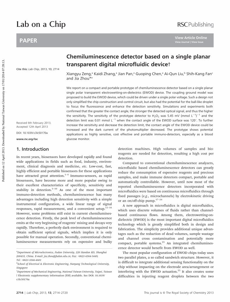
In this paper, we propose an integrated chemiluminescencedetector based on a 2-dimensional (2D) transparent singleplanar EWOD chip with a coupling ground. The setup isillustrated in Fig. 1. The size of the detector is about 7 6 7 6 7cm3. It is composed of a photomultiplier for sensingfluorescence, a 2D transparent EWOD chip for bio-reagentmanipulation and circuits for the detection of optical signals.A prototype of the detector was built up.
The highlight of our proposed integrated chemilumines-cence detector is the single planar EWOD device based on acoupling ground model detailed in section 2.1. Thus, theEWOD could be driven under a single polar voltage. This wasverified theoretically by simulation and experimentally. Inaddition, the optical signal enhancement effect of the ball-likedroplet located on the single planar EWOD device wassimulated and presented in practice.
As an application of the prototype, the H2O2-luminol (3-aminophthalhydrazide)-HRP (horse radish peroxidase) systemwas utilized for chemiluminescence detection. Such a systemcan be used in a great many biomedical detections and clinicaldiagnoses, such as the detection of DNA, small biomolecules,tumor markers, blood glucose, etc.30–33 For example, in bloodglucose detection, the key step is measuring the H2O2
concentration by luminol-HRP reagents, which indicates theconcentration of glucose in blood directly as shown in thefollowing reaction.
Glucose-oxidase (GOD) oxidizes the blood glucose andproduces H2O2. In phosphate buffered saline (PBS) solution(pH = 8y9), HRP catalyzes the oxidation of luminol by H2O2,producing 3-aminophthalate and emitting fluorescence.
Chemiluminescence signals were measured for H2O2
concentrations ranging from 0.01 mmol L21 to 100 mmolL21. The detection limit, the linear detection range and thesensitivity of prototype detector were determined by ananalysis of the experimental results.
Such a chemiluminescence detector shows the potential forhigh sensitivity, cost effectiveness and portable use as animmuno-detector, especially blood glucose monitoring, com-pared with traditional chemiluminescence detection instru-ments.
2. Principles
2.1 Coupling ground model for single polar electrode controlof a single planar EWOD
Coupling ground is well-known and widely used in manydevices. In one type of capacitive touch sensor, a user’s touchis detected based on the virtual capacitive coupling to earthground.34 Another example can be demonstrated by thecoupling voltage of power frequency signal in one’s body.This can be detected by an oscilloscope when its signal probeis held. This is because most objects containing metal or waterare coupled to the earth ground through the virtual capaci-tance. Applying this phenomenon in EWOD, we describe asingle planar configuration by a coupling ground model asshown in Fig. 2.
Fig. 2 illustrates the equivalent circuits of EWOD based onthe coupling ground model (Fig. 2 (a)) and the conventionalEWOD (Fig. 2 (b)).
In contrast to the conventional EWOD (in which the dropletconnects to the ground directly through the probe), in thecoupling ground model, the droplet is coupled to the groundthrough the equivalent coupling capacitance Ct. Vc is thecoupling voltage between the power source and groundvoltage. Therefore, the ground electrode as in the conventionalEWOD can be removed. Only one polar of the driving source isneeded for droplet manipulation by applying it on the drivingelectrodes of the EWOD device. Thus we would name our
Fig. 1 Schematic of the chemiluminescence detector. It includes a single planarEWOD device, a photomultiplier and circuits for the detection of optical signals.In this portable detector, reagent droplets can be manipulated automatically.The chemiluminescence can be focused on the surface of the photomultiplier bythe ball-like droplet with high sensitivity.
This journal is � The Royal Society of Chemistry 2013 Lab Chip, 2013, 13, 2714–2720 | 2715
digital microfluidic design as a single planar single polarEWOD.
Referring to the coupling voltage detection on one’s bodydetailed in the beginning of section 2.1, the coupling groundcapacitance can be verified by measuring the approximatecoupling voltage on the droplet. We connected the planarelectrode of EWOD to the red polar of a power source and letthe ground of the source (black polar) float. Vc was detected by
an oscilloscope with its signal probe touching the droplet andthe ground floated.
As shown in Fig. 3, the coupling voltage is does not equalzero or the source voltage, which implies the existence of thecoupling capacitance and the coupling ground.
The reliability of the coupling ground was verified on anindium tin oxide (ITO) glass substrate, as shown in Fig. 4. Theelectrowetting phenomenon was successfully demonstratedunder a driving voltage of 80 V with a frequency of 1 kHz. Thevoltage was applied on the driving electrode with one polarpower source as in Fig. 2 (a).
Droplet movement was realized based on the same principleas illustrated in Fig. 5 (a). A single polar of the AC voltage wasapplied on the ‘‘on’’ electrode next to the droplet and all theother electrodes remained floated. The droplet would move tothe ‘‘on’’ electrode. The result is shown in Fig. 5 (b). When thevoltage was applied sequentially to the electrodes, the dropletmoved up and down successfully and smoothly.
Fig. 2 Equivalent circuits of (a) EWOD with coupling ground and (b) conven-tional EWOD devices. Vc is the coupling voltage on the droplet.
Fig. 3 Coupling voltage on the droplet vs. source frequency.
Fig. 5 Droplet movement on a EWOD device with coupling ground (a)schematic of experiment; (b) pictures of droplet movement driven by singlepolar source.
Fig. 4 Droplet electrowetting on a single planar EWOD with coupling ground driven by an AC voltage of 80 V with frequency of 1 kHz.
2716 | Lab Chip, 2013, 13, 2714–2720 This journal is � The Royal Society of Chemistry 2013
Such a single planar single polar driving mode not onlysimplifies the control circuit by removing of all the groundlines, but it also keeps the droplet ball-like as it stays on thehydrophobic surface of the EWOD, which can enhance theoptical signal greatly as follows.
2.2 Enhancement of fluorescence signal on single planarEWOD device
Fig. 6 illustrates the realization of the light focusing on atraditional sandwich structure (a) and a single planar structure(b). In Fig. 6 (a), if there is no lens, the fluorescence light lackssufficient total reflection inside the droplet with the sandwichstructure so that it cannot be focused on the photomultiplierefficiently. In addition, compared to Fig. 6 (b), the thickness ofthe fluorescence droplet in the sandwich structure is far lessthan that of a single planar structure. Thus, the fluorescenceintensity in a unit horizontal area in the sandwich structure isfar smaller than that on the single planar structure.
The relationship between the droplet shape and theilluminance at the receiving surface of the photomultiplierwas simulated by a ray-tracing method (see Fig. 6 (c)). Asandwich structure with a gap of 0.1 mm and 0.5 mm betweenthe top and bottom electrodes, and a single planar structurewith surface contact angles of 45u, 70u, 90u and 120u were usedto calculate the relationship. The droplets for all calculationswere homogeneous self-luminous with the same volume of 30mL.
It is obvious that the illuminance of the fluorescence dropleton the single planar structure is several times larger than thatin the sandwich structure. Even the illuminance of a dropleton the single planar structure with the contact angle of 45u islarger than that in the sandwich structure with 0.5 mm spacerand several times larger than that in the sandwich structurewith 0.1 mm spacer, which is the most common spacerthickness. For the single planar structure, it was found that thegreater the contact angle, the stronger the optical signaldetected. The peak width of the curves also shows that thegreater the contact angle, the stronger the ability to focus light.
Fig. 6 Schematic and simulation of the fluorescence focus effect of a self-luminous droplet (30 mL): (a) A lens is needed to focus light in a conventionalsandwich EWOD device; (b) A hydrophobic single planar EWOD device focuseslight by the spherical droplet itself; (c) Ray-tracing simulation results of therelative fluorescence illuminance distribution on the surface of the photo-multiplier changing with the contact angle in a single planar EWOD device andthe space thickness in a sandwich structure.
Fig. 7 Prototype photo of chemiluminescence detector. The single planar singlepolar EWOD chip was stuck on the photomultiplier directly.
This journal is � The Royal Society of Chemistry 2013 Lab Chip, 2013, 13, 2714–2720 | 2717
3.1 Fabrication of a single planar transparent EWOD chip
Taking the advantages of the single planar EWOD device andthe self-luminous droplet on it, a tentative and practicalchemiluminescence detector was proposed.
A transparent single planar single polar EWOD chip formixing four reagents was fabricated. The process started bycleaning the 1 mm thick ITO glass. Then the ITO electrodeswere patterned after lithography and wet etching in 65 uCHNO3 : HCl : H2O = 1 : 3 : 6 solution for 1 min. Afterremoval of the photoresist and cleaning, a layer of 130 nmHfO2 was deposited by ALD (atomic layer deposition; 1000deposition cycle). Then a layer of 1 mm SU-8 2002(Microchem) was spin-coated at 6000 rpm for 30 s. The laststep was to spin-coat 50 nm Teflon1AF 2400 at 4000 rpm for30 s.
3.2 System assembly
The single planar single polar EWOD chip was stuck onto aphotomultiplier (SenSL, MiniSL-30035-X08, the active areawas 9 mm2) directly. All components were placed in alightproof box, inside the wall of which there was some softiron inside to shield any environmental electromagneticinterference.
The circuit for detection of the optical signal was alsolocated in the box. The amplifier circuit included a 40 Hz cut-off low-pass filter and a 1006 amplifier. It should be noted themagnification is limited by the dark current of the photo-multiplier. Fig. 7 shows the assembled prototype of thechemiluminescence detector ready for use.
4. Characterization and chemiluminescencedetection
4.1 Characterization of the detector
The relationship of contact angle vs. control voltage wasmeasured by a contact angle tester (Kruss FM40Mk2), asshown in Fig. 8.
The applied voltage was an AC signal with a frequency of 1kHz. The characterization was carried out under single polardriving mode. The typical pictures captured by the tester areshown in the inset of Fig. 8.
In Fig. 8, the numerical curve was calculated by theLippmann equation. There are some differences between theexperimental and numerical results, which possibly comesfrom complex coupling capacitance in the single planarstructure under a single polar driving mode.
A commercial product, TIANGEN1 Pro-Light HRPChemiluminescence Kit was used to determine the focuseffect of the contact angle on chemiluminescence detection.100mg L21 HRP was added to the kit and the chemilumines-cence signals generated were obtained based on differentcontact angles.
Fig. 9 gives the experimental and simulation results by theray-tracing method. It shows that single planar single polarEWOD device with a contact angle of 120u can enhance thereceived fluorescence signal almost twice as much as that ofthe device with a contact angle of 45u. The simulated lightpower gives the same trend as the electric signals we detected.
4.2 Application of the chemiluminescence detector
The H2O2-luminol-HRP system was utilized in the chemilumi-nescence detection. Additionally, PIP(4-iodophenol) was addedto enhance the chemiluminescence efficiency.
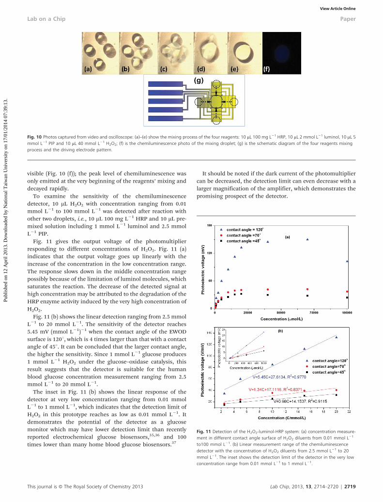
Fig. 10(a)–(e) show that four reagent droplets (10 mL 100 mgL21 HRP, 10 mL 2 mmol L21 luminol, 10 mL 5 mmol L21 PIP, 10mL 40 mmol L21 H2O2) were driven by the single polar voltageof 80 V at 1 kHz. The reagent mixing process and the electrodepattern are shown in Fig. 10(g). The chemiluminescence was
Fig. 8 Relationship between the contact angle and control voltage. The red dotsare the experimental results measured on the single planar chip. The blue curveis the theoretical result by Lippmann’s equation. The inset pictures show thatthe contact angle measurement is conducted under single polar driving: (a)before driving voltage applied; (b) after driving voltage applied.
Fig. 9 Experimental results of the contact angle vs. output voltage of thephotomultiplier (blue), and simulation results of the contact angle vs. lightpower of the photomultiplier received (red).
2718 | Lab Chip, 2013, 13, 2714–2720 This journal is � The Royal Society of Chemistry 2013
visible (Fig. 10 (f)); the peak level of chemiluminescence wasonly emitted at the very beginning of the reagents’ mixing anddecayed rapidly.
To examine the sensitivity of the chemiluminescencedetector, 10 mL H2O2 with concentration ranging from 0.01mmol L21 to 100 mmol L21 was detected after reaction withother two droplets, i.e., 10 mL 100 mg L21 HRP and 10 mL pre-mixed solution including 1 mmol L21 luminol and 2.5 mmolL21 PIP.
Fig. 11 gives the output voltage of the photomultiplierresponding to different concentrations of H2O2. Fig. 11 (a)indicates that the output voltage goes up linearly with theincrease of the concentration in the low concentration range.The response slows down in the middle concentration rangepossibly because of the limitation of luminol molecules, whichsaturates the reaction. The decrease of the detected signal athigh concentration may be attributed to the degradation of theHRP enzyme activity induced by the very high concentration ofH2O2.
Fig. 11 (b) shows the linear detection ranging from 2.5 mmolL21 to 20 mmol L21. The sensitivity of the detector reaches5.45 mV (mmol L21)21 when the contact angle of the EWODsurface is 120u, which is 4 times larger than that with a contactangle of 45u. It can be concluded that the larger contact angle,the higher the sensitivity. Since 1 mmol L21 glucose produces1 mmol L21 H2O2 under the glucose–oxidase catalysis, thisresult suggests that the detector is suitable for the humanblood glucose concentration measurement ranging from 2.5mmol L21 to 20 mmol L21.
The inset in Fig. 11 (b) shows the linear response of thedetector at very low concentration ranging from 0.01 mmolL21 to 1 mmol L21, which indicates that the detection limit ofH2O2 in this prototype reaches as low as 0.01 mmol L21. Itdemonstrates the potential of the detector as a glucosemonitor which may have lower detection limit than recentlyreported electrochemical glucose biosensors,35,36 and 100times lower than many home blood glucose biosensors.37
It should be noted if the dark current of the photomultipliercan be decreased, the detection limit can even decrease with alarger magnification of the amplifier, which demonstrates thepromising prospect of the detector.
Fig. 10 Photos captured from video and oscilloscope: (a)–(e) show the mixing process of the four reagents: 10 mL 100 mg L21 HRP, 10 mL 2 mmol L21 luminol, 10 mL 5mmol L21 PIP and 10 mL 40 mmol L21 H2O2; (f) is the chemiluminescence photo of the mixing droplet; (g) is the schematic diagram of the four reagents mixingprocess and the driving electrode pattern.
Fig. 11 Detection of the H2O2-luminol-HRP system: (a) concentration measure-ment in different contact angle surface of H2O2 diluents from 0.01 mmol L21
to100 mmol L21. (b) Linear measurement range of the chemiluminescencedetector with the concentration of H2O2 diluents from 2.5 mmol L21 to 20mmol L21. The inset shows the detection limit of the detector in the very lowconcentration range from 0.01 mmol L21 to 1 mmol L21.
This journal is � The Royal Society of Chemistry 2013 Lab Chip, 2013, 13, 2714–2720 | 2719
We report the prototype of a compact and portable chemilu-minescence detector composed of a single planar single polartransparent EWOD device, photomultiplier and circuits foroptical detection. The single planar single polar EWOD devicewas built up based on a coupling ground model that could bedriven under a single polar voltage. Such a design not onlysimplified the chip construction and control circuit, but alsohad the potential for the ball-like droplet to focus thefluorescence and enhance the detection sensitivity.Simulations and experiments both confirmed that the greaterthe contact angle, the stronger the detected optical signal, andthus the higher the sensitivity.
The sensitivity of the prototype detector was 5.45 mV (mmolL21)21 and the detection limit was 0.01 mmol L21 when thecontact angle was 120u. Further increase of the sensitivity anddecrease of the detection limit can be achieved by increasingthe contact angle of the EWOD device and decreasing the darkcurrent of the photomultiplier.
The prototype shows potential applications as highlysensitive, cost effective and portable immuno-detectors,especially as a blood glucose monitor
References
1 S. P. Mohanty, IEEE Potentials, 2006, 25, 35.2 R. Monosık, M. Stredansky and E. Sturdık, Acta Chimica
Slovaca, 2012, 5, 109.3 A. C. Matthew, Nat. Rev. Drug Discovery, 2002, 1, 515.4 X. Fan, M. W. Ian, I. S. Siyka, H. Zhu, D. S. Jonathan and
Y. Sun, Anal. Chim. Acta, 2008, 620, 8.5 P. B. Luppa, L. J. Sokoll and D. W. Chan, Clin. Chim. Acta,
2001, 314, 1.6 F. Ricci, G. Adornetto and G. Palleschi, Electrochim. Acta,
2012, 84, 74.7 V. C. Bhaskara, A. B. Ashwinkumar, Y. M. Nicole, S.
E. Henry and X. Chen, ACS Nano, 2012, 6, 6546.8 J. F. Rusling, Chem. Rec., 2012, 12, 164.9 T. R. J. Holford, Biosens. Bioelectron., 2012, 34, 12.
10 S. Kobayashi, ICKS’04 Proceedings of the InternationalConference on Informatics Research for Development ofKnowledge Society Infrastructure, 2004, 65.
11 K. Kaura, B. Singha and A. K. Malika, Anal. Lett., 2011, 44,1602.
12 D. Christodouleas, C. Fotakis, A. Economou, K. Papadopoulos,M. Timotheou-Potamia and A. Calokerinos, Anal. Lett., 2011,44, 176.
13 F. J. Lara, A. M. Garcıa-Campana and J. J. Aaron, Anal.Chim. Acta, 2010, 679, 17.
14 M. Liu, Z. Lin and J.-M. Lin, Anal. Chim. Acta, 2010, 670, 1.15 L. Gamiz-Gracia, A. M. Garcıa-Campana, J. F. Huertas-Perez
and F. J. Lara, Anal. Chim. Acta, 2009, 640, 7.16 S. Okumoto, A. Jones and W. B. Frommer, Annu. Rev. Plant
Biol., 2012, 63, 663.17 X. Chen, C. Liu, Z. Xu, Y. Pan, J. Liu and L. Du, Microsyst.
Technol., 2013, 19, 99.18 M. Kamruzzaman, A.-M. Alam, K. M. Kim, S. H. Lee, Y.
H. Kim, A. N. M. H. Kabir, G.-M. Kim and T. D. Dang,Biomed. Microdevices, 2013, 15, 195.
19 A. Bromberg and R. A. Mathies, Electrophoresis, 2004, 25,1895.
20 D. Yang, X. Niu, Y. Liu, Y. Wang, X. Gu, L. Song, R. Zhao,L. Ma, Y. Shao and X. Jiang, Adv. Mater., 2008, 20, 4770.
21 H. Qiu, L. Fan, X. Li, L. S. M. Li and C. Luo, J. Pharm.Biomed. Anal., 2012, 75, 123.