About the Tower System TWR-MCF5225X Module Mini-B USB Connector Functional Elevator Dummy Elevator Ethernet Connector TWR-SER Module Figure 1: Tower System TWR-MCF5225X-KIT Freescale Tower System The TWR-MCF5225X module is part of the Freescale Tower System, a modular development platform that enables rapid prototyping and tool re-use through reconfigurable hardware. Take your design to the next level and begin constructing your Tower System today. Get to know the TWR-MCF5225X Primary Connector RS232 Port MCF5225X OSBDM Mini-B USB Connector Secondary Connector Potentiometer LED1-LED4 SW1 SW3 SW4/Reset Accelerometer TOWER SYSTEM Lab Tutorials for TWR-MCF5225X TOWER SYSTEM Lab Tutorials for TWR-MCF5225X MCF5225X Connectivity Labs 2, 3 and 4
Transcript
About the Tower System
TWR-MCF5225X Module
Mini-B USB Connector
Functional Elevator
Dummy Elevator
Ethernet Connector
TWR-SER Module
Figure 1: Tower System
TWR-MCF5225X-KIT Freescale Tower SystemThe TWR-MCF5225X module is part of the Freescale Tower System, a modular development platform that enables rapid prototyping and tool re-use through reconfigurable hardware. Take your design to the next level and begin constructing your Tower System today.
Get to know the TWR-MCF5225X
Primary Connector
RS232 Port
MCF5225X
OSBDM Mini-B USB Connector
Secondary Connector
Potentiometer
LED1-LED4
SW1
SW3
SW4/Reset
Accelerometer
TOWER SYSTEMLab Tutorials for TWR-MCF5225X
continued from reverse side...4. The default IP address of the board is
169.254.3.3. Typically, when you connect your computer directly to the board, the computer will default to an auto IP address on the same subnet as the board (169.254.x.x), therefore requiring no setup. Note: The PC may take a few minutes to default to the auto IP address and make the connection.
However, if you have trouble connecting, you may configure the IP address of the computer manually. Select Start > Settings > Network Connections > Local Area Connection. Note your original TCP/IP settings, and then set your IP address to 169.254.3.4 and your subnet mask to 255.255.0.0.
5. Open the HVAC.h file in the CodeWarrior window. Double-click the file item located in the “Source/HVAC” group in the CodeWarrior project tree.
6. Locate the line of code starting with #define ENET_IPADDR and specify your target IP address by using the IPADDR macro. Set the target address to 169.254.3.3, and the line will be:
#define ENET_IPADDR IPADDR(169,254,3,3)7. Do the same with the IP address mask value
8. Compile, download and run the application and open a hyperterminal window as was done in steps 8 to 15 of Lab 1.
9. Start your Internet browser and navigate to the target device address. In this case, 169.254.3.3.
10. You should see the Web server welcome page in the browser window.
Figure 1: MQX source tree
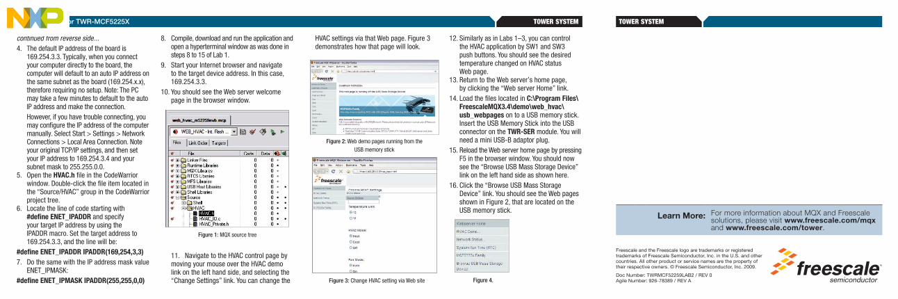
11. Navigate to the HVAC control page by moving your mouse over the HVAC demo link on the left hand side, and selecting the “Change Settings” link. You can change the
HVAC settings via that Web page. Figure 3 demonstrates how that page will look.
12. Similarly as in Labs 1–3, you can control the HVAC application by SW1 and SW3 push buttons. You should see the desired temperature changed on HVAC status Web page.
13. Return to the Web server’s home page, by clicking the “Web server Home” link.
14. Load the files located in C:\Program Files\FreescaleMQX3.4\demo\web_hvac\usb_webpages on to a USB memory stick. Insert the USB Memory Stick into the USB connector on the TWR-SER module. You will need a mini USB-B adaptor plug.
15. Reload the Web server home page by pressing F5 in the browser window. You should now see the “Browse USB Mass Storage Device” link on the left hand side as shown here.
16. Click the “Browse USB Mass Storage Device” link. You should see the Web pages shown in Figure 2, that are located on the USB memory stick.
Figure 4.
Figure 2: Web demo pages running from the USB memory stick
Figure 3: Change HVAC setting via Web site
TOWER SYSTEMLab Tutorials for TWR-MCF5225X
Learn More: For more information about MQX and Freescale solutions, please visit www.freescale.com/mqx and www.freescale.com/tower.
2 USB Functionality, Freescale MQX USB and MFSThis lab will guide you through the use of the USB stack, the MFS file system and the logging of data to the memory stick.
Demonstrates• USBhostfunctionalitywithmassstorage
class support• USBdrivereadandwriteaccessbyusingthe
MFS file system component
Note: The USB labs in this document require a USB memory stick and USB A to Mini-B converter, which are not included.
Step by Step Instructions1. Stop the application in CodeWarrior™
if it is currently running (Debug>Kill) 2. Open hvac.h in CodeWarrior
Figure 1: MQX Source Tree
3. Enable the USB support by changing:#define DEMOCFG_ENABLE_USB_FILESYSTEM 0 to:#define DEMOCFG_ENABLE_USB_FILESYSTEM 14. Recompile the code, download, and run the
application as was done in steps 8 to 15 of Lab 1.
5. Load the files located in C:\Program Files\FreescaleMQX3.4\demo\web_hvac\usb_webpages on to a USB memory stick.
Then insert the USB memory stick into the USB connector on the TWR-SER board. You will need the mini USB-B adaptor plug. See Figure 2 on the next page.
6. On the hyperterminal console you should see text that indicates that the USB memory stick was found, the type of memory stick that was found, the USB mass storage device was opened, the partition manager was installed, and that the file system was installed and opened. It may take several seconds to fully install the memory stick. It will look like Figure 3.
Figure 3: Inserting a USB mass storage device
Figure 2: Plugging in the USB stick
7. Press return on the PC to get the shell> prompt.
8. Type help to see the list of commands. You should see additional commands available as seen in Figure 4. You can use the commands to exercise the memory stick attached.
9. Type dir to see the memory stick directory listing.
10. The logging information is now being sent to the memory stick in file hvac_log.txt instead of being printed to the serial port. You should see this file in the directory listing. Note the file size of hvac_log.txt.
11. Press SW1 and SW3 a few times each to change the desired temperature.
12. Type dir again in the shell and note the file size of hvac_log.txt. It should be bigger than
before indicating that the changed parameters are being logged to the memory stick.
13. Use the type command to display the contents of the log file located on the memory stick (type hvac_log.txt). It will look like Figure 5.
Figure 4: Shell commands with USB functionality enabled
Figure 5: HVAC log file contents
14. Delete the log file using the del command (del hvac_log.txt). Once again view the directory listing to verify that the file has been removed.
15. Within 15 seconds (or after SW1/SW3 key press) you should see that the log file has been recreated. Use the type command on the log file (type hvac_log.txt) to see the latest entry.
LAB
3 Telnet and FTP Operation, Freescale MQX RTCSThis lab will introduce you to the use of Telnet and FTP to access a product remotely via Ethernet and TCP/IP protocols.
Step by Step Instructions1. Stop the application if it is currently running
(Debug>Kill).2. Connect an Ethernet cable between the
TWR-SER board and an Ethernet port on your computer.
3. The default IP address of the board is 169.254.3.3. Typically, when you connect your computer directly to the board, the computer will default to an auto IP address on the same subnet as the board (169.254.x.x), therefore requiring no setup. Note: The PC may take a few minutes to default to the auto IP address and make the connection.
However, if you have trouble connecting, you may configure the IP address of the computer manually. Select Start > Settings > Network Connections > Local Area Connection. Note your original TCP/IP settings, and then set your IP address to 169.254.3.4 and your subnet mask to 255.255.0.0.
4. Open the HVAC.h file in the CodeWarrior window. Double-click the file item located in the “Source/HVAC” group in the CodeWarrior project tree.
5. Locate the line of code starting with #define ENET_IPADDR and specify your target IP address by using the IPADDR macro. Use the IP address 169.254.3.3 if it has not already been set:
#define ENET_IPADDR IPADDR(169,254,3,3)6. Do the same with the IP address mask value
ENET_IPMASK:#define ENET_IPMASK IPADDR(255,255,0,0)7. In the same HVAC.h file, enable RTCS and
Telnet servers by changing this:#define DEMOCFG_ENABLE_RTCS 0#define DEMOCFG_ENABLE_FTP_SERVER 0#define DEMOCFG_ENABLE_TELNET_SERVER 0 to this:#define DEMOCFG_ENABLE_RTCS 1#define DEMOCFG_ENABLE_FTP_SERVER 0#define DEMOCFG_ENABLE_TELNET_SERVER 18. Recompile the code, download and run the
application as was done in steps 8 to 15 of Lab 1. Then plug in the USB stick as done in Lab 2.
9. Open a command prompt on the PC (Start > Programs > Accessories > Command Prompt)
10. At the prompt invoke a telnet session to the board by typing telnet 169.254.3.3 you will be connected to the MQX shell via telnet.
Figure 1: Connect to telnet
Figure 2: Using shell commands over telnet
Figure 3: Communicating with FTP
11. The telnet shell has its own command set, which is similar to the terminal shell commands as in the previous labs. Try the help and info commands.
12. Try the log command to print content of the hvac_log.txt file to the telnet console.
13. In the same HVAC.h file, disable Telnet and enable the FTP server by changing this:
#define DEMOCFG_ENABLE_RTCS 1#define DEMOCFG_ENABLE_FTP_SERVER 0#define DEMOCFG_ENABLE_TELNET_SERVER 1 to this:#define DEMOCFG_ENABLE_RTCS 1#define DEMOCFG_ENABLE_FTP_SERVER 1#define DEMOCFG_ENABLE_TELNET_SERVER 014. Recompile the code, download, and run the
application as was done in steps 8 to 15 of Lab 1.
15. Open a second command prompt (Start > All Programs > Accessories > Command Prompt) and change the working directory for the prompt to the c:\Freescale folder (type “c:”, “cd \”, “mkdir Freescale” and
“cd Freescale” commands). See Figure 3 below for an example.
16. Start the ftp session by typing the following in the Windows command prompt:
>ftp 169.254.3.3 For the user name, press
Enter to leave it blank.
User (169.254.3.3(none)): 17. Get the USB memory stick directory listing in
the ftp session by the ls command.18. Use get hvac_log.txt command in the ftp
session to retrieve the log file. The file will be copied to the local working directory c:\Freescale. Open the local file with notepad to verify that the file was copied properly.
LAB
4
Web-Enabled HVAC System, Freescale MQX RTCSThis lab extends the HVAC application described in Labs 1–3 and adds Web server functionality. The dynamic Web pages serve as a graphical user’s interface to the HVAC application.
Step by Step Instructions1. Make the following connections from the
Tower System to the computer. a. USB debugger connection (J17 on the TWR-
MCF5225X module) to a USB port on PC b. Serial port on the TWR-SER module to a
serial port on PC (serial cable not included) c. An Ethernet cable between the TWR-SER
module and Ethernet port on your computer2. The first time you connect the USB debugger
cable to your PC, Windows will install a driver for the debugger. Follow the prompts to automatically detect and install the driver.
3. Open the lab project by selecting the File > Open menu item: C:\Program Files\FreescaleMQX3.4\demo\web_hvac\codewarrior\web_hvac_twrmcf52259.mcp
MCF5225X—Lab Tutorials 2, 3 and 4 (sheet 2 of 3)
TOWER SYSTEMLab Tutorials for TWR-MCF5225X
Mini-B USB
About the Tower System
TWR-MCF5225X Module
Mini-B USB Connector
Functional Elevator
Dummy Elevator
Ethernet Connector
TWR-SER Module
Figure 1: Tower System
TWR-MCF5225X-KIT Freescale Tower SystemThe TWR-MCF5225X module is part of the Freescale Tower System, a modular development platform that enables rapid prototyping and tool re-use through reconfigurable hardware. Take your design to the next level and begin constructing your Tower System today.
Get to know the TWR-MCF5225X
Primary Connector
RS232 Port
MCF5225X
OSBDM Mini-B USB Connector
Secondary Connector
Potentiometer
LED1-LED4
SW1
SW3
SW4/Reset
Accelerometer
TOWER SYSTEMLab Tutorials for TWR-MCF5225X
continued from reverse side...4. The default IP address of the board is
169.254.3.3. Typically, when you connect your computer directly to the board, the computer will default to an auto IP address on the same subnet as the board (169.254.x.x), therefore requiring no setup. Note: The PC may take a few minutes to default to the auto IP address and make the connection.
However, if you have trouble connecting, you may configure the IP address of the computer manually. Select Start > Settings > Network Connections > Local Area Connection. Note your original TCP/IP settings, and then set your IP address to 169.254.3.4 and your subnet mask to 255.255.0.0.
5. Open the HVAC.h file in the CodeWarrior window. Double-click the file item located in the “Source/HVAC” group in the CodeWarrior project tree.
6. Locate the line of code starting with #define ENET_IPADDR and specify your target IP address by using the IPADDR macro. Set the target address to 169.254.3.3, and the line will be:
#define ENET_IPADDR IPADDR(169,254,3,3)7. Do the same with the IP address mask value
8. Compile, download and run the application and open a hyperterminal window as was done in steps 8 to 15 of Lab 1.
9. Start your Internet browser and navigate to the target device address. In this case, 169.254.3.3.
10. You should see the Web server welcome page in the browser window.
Figure 1: MQX source tree
11. Navigate to the HVAC control page by moving your mouse over the HVAC demo link on the left hand side, and selecting the “Change Settings” link. You can change the
HVAC settings via that Web page. Figure 3 demonstrates how that page will look.
12. Similarly as in Labs 1–3, you can control the HVAC application by SW1 and SW3 push buttons. You should see the desired temperature changed on HVAC status Web page.
13. Return to the Web server’s home page, by clicking the “Web server Home” link.
14. Load the files located in C:\Program Files\FreescaleMQX3.4\demo\web_hvac\usb_webpages on to a USB memory stick. Insert the USB Memory Stick into the USB connector on the TWR-SER module. You will need a mini USB-B adaptor plug.
15. Reload the Web server home page by pressing F5 in the browser window. You should now see the “Browse USB Mass Storage Device” link on the left hand side as shown here.
16. Click the “Browse USB Mass Storage Device” link. You should see the Web pages shown in Figure 2, that are located on the USB memory stick.
Figure 4.
Figure 2: Web demo pages running from the USB memory stick
Figure 3: Change HVAC setting via Web site
TOWER SYSTEMLab Tutorials for TWR-MCF5225X
Learn More: For more information about MQX and Freescale solutions, please visit www.freescale.com/mqx and www.freescale.com/tower.