8
Laboratory Exhaust Systems Vektor ® -CH and Vektor ® -CD Centrifugal High Plume and High Plume Dilution Exhaust System February 2018
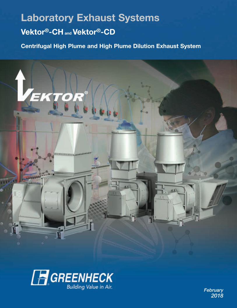
Laboratory Exhaust SystemsVektor®-CH and Vektor®-CD
Centrifugal High Plume and High Plume Dilution Exhaust System
February 2018

22
Vektor-CH High Plume and Vektor-CD High Plume Dilution Exhaust System
Vektor-CH and Vektor-CD are listed for Electrical UL/cUL 705 – File no. 40001
Vektor-CD PatentsManufactured by Greenheck Fan Corp.
under the following patent numbers:U.S. Patents: No. 7547249
Singapore Patents:No. 124105
Other U.S. and Foreign Patents Pending
Vektor CH and CD Applications• Laboratories:
– Biological– Chemical– Animal (vivarium)– Physical
• Pharmaceutical companies• Research facilities• Industrial processes
– High velocity exhaust effluent for high plume heights
– System designed specifically for reliability required in life safety applications
– Distributed weight loading and lower system profile
– 125 mph (201 km/h) high wind loading without guy wires
– AMCA Spark C resistant construction standard (AMCA Spark B optional)
– Air handling quality bearings with L10 80k hour rated bearing life
– Single source responsibility - removing performance, fit-up and component misapplication issues
– Motors, drives and bearings are at roof deck level for safety and easy servicing
– Seismic control restrained spring isolators selected for use in critical areas and sized for a complete system
– High efficiency centrifugal wheel and scroll housings engineered for reduced turbulence and aerodynamic efficiency
– Engineered and tested for structural integrity with certified air and sound performance
– Chemical resistant flex connections for quick installation
– Low maintenance direct drive option, one year motor lubrication interval
Vektor-CH and CD fan systems are designed for compliance to ANSI Z9.5, NFPA 45, and UL 705 Standards and codes for laboratory exhaust fans. In addition, Vektor systems follow the latest ASHRAE HVAC Applications Handbook (Chapter 45) and ASHRAE Laboratory Design Guidelines. Vektor-CH and CD fan systems are designed to withstand 125 mph (201 km/h) windloading without the use of guy wires.
Greenheck’s pre-engineered system, Vektor-CH and Vektor-CD centrifugal based exhaust fans offer high efficiency and high capacity operation with flexible laboratory exhaust designs for chemical, fume, or odors. The Vektor-CH and Vektor-CD feature advanced technology designed to safely and effectively remove, project and disperse laboratory exhaust safely away from the building. These models provide flexibility in your system for bypass air, dilution air, demand based staged operation and system redundancy. CH and CD models have high pressure capabilities to handle increased system pressure from additional components such as high efficiency filtration, UV light treatment, scrubbers or odor removal treatment.
Vektor-CD
Vektor-CH
Vektor-CH and CD Value Benefits and Advantages
33
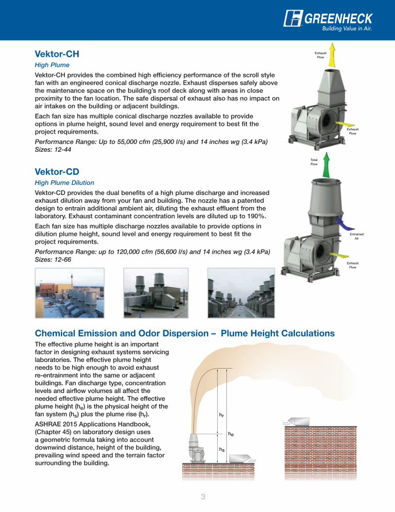
Vektor-CHHigh Plume
Vektor-CH provides the combined high efficiency performance of the scroll style fan with an engineered conical discharge nozzle. Exhaust disperses safely above the maintenance space on the building’s roof deck along with areas in close proximity to the fan location. The safe dispersal of exhaust also has no impact on air intakes on the building or adjacent buildings.
Each fan size has multiple conical discharge nozzles available to provide options in plume height, sound level and energy requirement to best fit the project requirements.
Performance Range: Up to 55,000 cfm (25,900 l/s) and 14 inches wg (3.4 kPa) Sizes: 12-44
Vektor-CDHigh Plume Dilution
Vektor-CD provides the dual benefits of a high plume discharge and increased exhaust dilution away from your fan and building. The nozzle has a patented design to entrain additional ambient air, diluting the exhaust effluent from the laboratory. Exhaust contaminant concentration levels are diluted up to 190%.
Each fan size has multiple discharge nozzles available to provide options in dilution plume height, sound level and energy requirement to best fit the project requirements.
Performance Range: up to 120,000 cfm (56,600 l/s) and 14 inches wg (3.4 kPa) Sizes: 12-66
Exhaust Flow
ExhaustFlow
ExhaustFlow
EntrainedAir
TotalFlow
Chemical Emission and Odor Dispersion – Plume Height CalculationsThe effective plume height is an important factor in designing exhaust systems servicing laboratories. The effective plume height needs to be high enough to avoid exhaust re-entrainment into the same or adjacent buildings. Fan discharge type, concentration levels and airflow volumes all affect the needed effective plume height. The effective plume height (he ) is the physical height of the fan system (hs ) plus the plume rise (hr ).
ASHRAE 2015 Applications Handbook, (Chapter 45) on laboratory design uses a geometric formula taking into account downwind distance, height of the building, prevailing wind speed and the terrain factor surrounding the building.
he
hs
hr

44
Pre-engineered Nozzle/Windband – Designed and tested with certified performance.
1
Transition and Flex Connection – Compact square-to-round transition from damper to fan inlet provides quick and easy fit-up. Transition is removable for damper inspection. Chemical and UV resistant flex material with stainless clamps connect the fan to the transition and plenum. Flex connection combined with vibration isolators effectively isolates the fan.
6
Centrifugal Wheel and Scroll Housing – High performance centrifugal wheels with flat or airfoil blades for increased efficiency, AMCA Spark C (standard) or AMCA Spark B (optional) resistant construction and all fasteners exposed to the air stream are stainless steel.
2
Shaft Seal – Shaft penetration into the fan housing is sealed to prevent contaminated exhaust from leaking into the surrounding area.
3
Shaft Bearing – Air handling quality with L10 80,000 hrs. (minimum) or L10 200,000 hrs. (optional) rated life. Bearings 100% inspected with tighter component tolerances and reduced swivel torque for improved alignment and fan operation. (Belt drive arrangement 10 and direct drive arrangement 8).
4
Formed Base and Seismic Isolators – Formed and coated steel base increases system structural rigidity. Restrained spring isolators, seismically rated to minimum 1.0 g, are sized for all components including stack, nozzle and windband.
5
Belt Drive Arrangement 10:
• Speed adjustment by sheave change
• Motor change out without accessing wheel
• Longer bearing life
6
8
10
1
2
3
4
5
Vektor-CH and Vektor-CDFeatures

55
4-6 mils Total
Zinc-rich Primer(70% zinc)
Hi-Pro Polyester
Base Steel
AdvancedSurface Preparation
LabCoat™ Cross Section
Value Added FeaturesComplete Fan System AMCA Licensed – Certified for Sound and Air Performance as a complete assembly including discharge nozzle and windband. All component losses are included during selection.
Windloading – Fan assemblies are able to withstand 125 mph (201 km/h) wind loading without the need for guy wires.
Vibration Testing – Vektor fans are vibration tested as a complete assembly and must pass AMCA 204 vibration standard BV-4, 0.10 in./s (2.5 mm/s) filter-in at the specified fan RPM.
Vibration testing is performed with tri-axial accelerometers that take measurements in three planes; vertical, axial and horizontal. Test results for each fan are stored as permanent record and are available upon request.
LabCoat™ Corrosion Resistant Coating – All steel components are electrostatically powder coated with corrosion resistant Hi-Pro Polyester topcoat and zinc rich epoxy primer, which protects against a wide spectrum of acids, alkalis and solvents.
Isolation Damper – Parallel airfoil blade dampers isolate individual fans from the plenum when not in operation as well as to prevent backward wheel rotation. Dampers are mounted to the exterior of the plenum allowing for service and inspection without entering into the contaminated bypass plenum.
8
Bypass Damper – Opposed airfoil blade dampers provide full airflow control throughout the damper’s operating range. Dilutes bypass air exhaust concentration levels prior to entering into the fan or balance building flow variations to maintain constant fan volume and set plume height. Dampers are sized specifically for volumes and pressures required on the application.
9
Bypass Air Plenum (BAP) – Common plenum to connect multiple fans to exhaust system. Plenum designed to minimize system effects based on the fan airflow capacities. Duct connection locations on bottom or side.
7
Actuators – Isolation and bypass air dampers are available with factory mounted electric actuators to expedite system installation and to contribute to a safe, operational lab system. Actuators selected and sized on project specific operating torque requirements and control needs.
10
Direct Drive Arrangement 4:
• Motor shaft connected to fan wheel
• One year motor lubrication interval
• Fewer components
Direct Drive Arrangement 8:
• Coupled motor and fan shaft
• Motor change out without accessing wheel
• Longer bearing life
9
10
7

66
Vektor-CH and Vektor-CD Monitoring
Sure-Aire™The Sure-Aire airflow monitoring station measures fan flow within an accuracy of 3%. Unlike traditional flow probes which are often mounted in the fan venturi and create a system effect hindering a fan’s performance, Sure-Aire does not interfere with airflow and will not impact the fan’s air or sound performance. This option is available on Vektor-CH and Vektor-CD models and ships completely assembled from our factory. An electronics package with pressure transmitter and digital read out is available with the Sure-Aire system. The electronic kits come in 50 or 60 Hz power supplies and provides a 4-20 mA or 0-10 volt output to tie into the building’s management system.
Fan Monitoring SystemGreenheck’s Fan Monitoring System is designed to allow facilities and maintenance managers the ability to stay connected with their critical ventilation products. The fan monitoring system package includes a pre-programmed electronic monitor along with a wide selection of commonly applied sensors to monitor the overall equipment health, plan maintenance, and energy usage.
Fan Monitoring System Benefits• Applicable to any fan type in easy-to-access or remote locations• Connects with Building Management System (BMS)• Customized to unique installations and applications• Schedule maintenance based on operation, not calendar dates
System Integration
Maintenance
Energy use
Process monitors
Fan condition
Sensor Packages:• Vibration (fan/motor)• Bearing temperature• System pressures• System temperatures (airstream)• Amp draw• Fan RPM
ActuatorsVektor systems are available with factory mounted and wired electric actuators. Each is sized and selected to handle the specific requirements of the laboratory application.
Isolation Damper Actuator Options Bypass Damper Actuator Options
2-position spring return actuator with end switches Modulating operation for bypass airflow control
Electronic actuatorsPower: 24 VAC/VDC, 115 VAC or 230 VAC (transformers optional)Control signal: 2-10 VDC or 4-20 mA
Electronic actuatorsPower: 24 VAC/VDC, 115 VAC or 230 VAC (transformers optional)Control signal: 2-10 VDC or 4-20mADC
Single point wiring of the transformer and actuator NEMA-1 enclosure (NEMA-4 enclosure optional)
NEMA-1 enclosure (NEMA-4 enclosure optional)
Isolation Damperand Actuator
77
Vektor-CH and Vektor-CD Product Selection
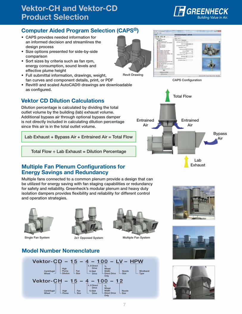
Model Number Nomenclature
Vektor-CD – 15 – 4 – 100 – LV – HPWHighPlumeDilution
CentrifugalWheel
4, 8 Direct Drive
10 Belt Drive
4, 8 Direct Drive
10 Belt Drive
%WheelWidthDirect DriveOnly
%WheelWidthDirect DriveOnly
NozzleSize
WindbandType
FanSize
Vektor-CH – 15 – 4 – 100 – 12
HighPlume
CentrifugalWheel
NozzleSize
FanSize
Multiple Fan Plenum Configurations for Energy Savings and RedundancyMultiple fans connected to a common plenum provide a design that can be utilized for energy saving with fan staging capabilities or redundancy for safety and reliability. Greenheck’s modular plenum and heavy duty isolation dampers provides flexibility and reliability for different control and operation strategies.
Single Fan System Multiple Fan System2x1 Opposed System
Computer Aided Program Selection (CAPS®)• CAPS provides needed information for
an informed decision and streamlines the design process
• Size options presented for side-by-side comparison
• Sort sizes by criteria such as fan rpm, energy consumption, sound levels and effective plume height
• Full submittal information, drawings, weight, fan curves and component details, print, or PDF
• Revit® and scaled AutoCAD® drawings are downloadable as configured.
CAPS Configuration
Revit Drawing
Vektor CD Dilution Calculations
Dilution percentage is calculated by dividing the total outlet volume by the building (lab) exhaust volume. Additional bypass air through optional bypass damper is not directly included in calculating dilution percentage since this air is in the total outlet volume.
Total Flow
EntrainedAir
EntrainedAir
LabExhaust
BypassAirLab Exhaust + Bypass Air + Entrained Air = Total Flow
Total Flow ÷ Lab Exhaust = Dilution Percentage

P.O. Box 410 • Schofield, WI 54476-0410 • Phone (715) 359-6171 • greenheck.com
As a result of our commitment to continuous improvement, Greenheck reserves the right to change specifications without notice.
Specific Greenheck product warranties are located on greenheck.com within the product area tabs and in the Library under Warranties.
Our Commitment
00.LAB.1017 R2 2-2018 RGCopyright © 2018 Greenheck Fan Corp.
Family of Lab Exhaust Systems
Prepared to SupportGreen Building Efforts
Vektor-MH• High Plume Nozzle• Mixed flow wheel /
bifurcated housing• Compact design• Up to 47,000 cfm and
11 in. wg
Vektor-CH• High Plume Nozzle• Centrifugal wheel• Up to 56,000 cfm and
12 in. wg
Vektor-H• High Plume Discharge Nozzle• Centrifugal wheel • Compact design / sealed
airstream components• Up to 26,000 cfm and 4 in. wg
High Plume - Effective means of creating a discharge plume height to prevent re-entrainment of chemical exhaust fumes into make-up air systems.
Vektor-MD• High Plume Discharge Nozzle with
Entrainment and Dilution • Mixed flow wheel / bifurcated housing• Compact design• Up to 83,000 cfm and 11.5 in. wg
Vektor-CD• High Plume Discharge Nozzle with
Entrainment and Dilution • Centrifugal wheel• Highest efficiency / easy service design• Up to 122,000 cfm and 13.5 in. wg
High Plume Dilution - Fan design that entrains and mixes outside ambient air into the exhaust airstream prior to exiting out the windband discharge. Potentially hazardous exhaust or exhaust fumes are diluted and dispersed quickly.
High Plume Variable Geometry Nozzle (VGN) - The discharge area automatically adjusts to maintain a constant discharge velocity and remain compliant to design codes. VGN maximizes effective plume heights during periods of reduced flow and lower discharge velocity fixed nozzles.
Vektor-HS• VGN discharge nozzle
technology• Variable volume flow –
constant velocity discharge• Centrifugal wheel• Up to 26,000 cfm and
3.5 in. wg
Vektor-MS• VGN discharge nozzle
technology• Variable volume flow –
constant velocity discharge• Mixed flow wheel / bifurcated
housing• Up to 32,000 cfm and
10 in. wg
Vektor-CS• VGN discharge nozzle
technology• Variable volume flow –
constant velocity discharge• Centrifugal wheel• Up to 32,000 cfm
and 10 in. wg


