Date post: | 29-Jul-2018 |
Category: |
Documents |
Upload: | truonglien |
View: | 216 times |
Download: | 0 times |
NASA CR-132266
N 7 3 31411
LABORATORY FOR ATMOSPHERIC AND SPACE PHYSICS
UNIVERSITY OF COLORADO
BOULDER, COLORADO
803O2
CCOPY
REPORT
ADVANCED APPLICATIONS FLIGHT EQUIPMENT (AAFE)
125mm ULTRAVIOLET SPECTROMETER
CONTRACT NAS I-10388
https://ntrs.nasa.gov/search.jsp?R=19730022679 2018-07-29T04:35:17+00:00Z
LABORATORY FOR ATMOSPHERIC AND SPACE PHYSICS
UNIVERSITY OF COLORADO
BOULDER, COLORADO
80302
FINAL REPORT
FOR
AAFE 125MM ULTRAVIOLET SPECTROMETER
CONTRACT :
DATE:
Approved:
NAS1-10388
December, 1972
Revised May, 1973
James D. CunninghamProgram Manager
<S
TABLE OF CONTENTS
ACKNOWLEDGMENTS
1.0 INTRODUCTION
2.0 PURPOSE
3.0 INSTRUMENT DESCRIPTION
3.1 Instrument Case
3.2 Optical - Mechanical Elements
3.2.1 Primary Mirror
3.2.2 Entrance Slit
3.2.3 Ebert Mirror
3.2.4 Grating
3.2.5 Exit Slit
3.2.6 Mirror Mounting
3.3 Light Shade
3.4 Monochromator
3.5 Grating Drive Mechanism
3.5.1 The Motor and Gearbox
3.6 Circuit Design and Testing
3.6.1 Photomultiplier Tubes (PMT)
3.6.2 Preamplifier Discriminator
3.6.3 Data Processor
3.6.4 Motor Drive
3.6.5 Optical Fiducial
3.6.6 Engineering Data
3.6.7 High Voltage Power Supply
2.6.8 Low Voltage Power Supply
4.0 ASSEMBLY, TEST AND CALIBRATION
4.1 Assembly
4.2 Test
4.3 Calibration
-i-
TABLE OF CONTENTS(Continued)
5.0 PERFORMANCE PARAMETERS
5.1 Spectral Range
5.2 Dynamic Range
5.3 Resolution
5.4 Accuracy
5.5 Scan Time
5.6 Sampling Rate
6.0 ADAPTIVE MODE REAL TIME ANALYSIS
6.1 Vertical Ozone Measurement Minimum Input Hypothesis
7.0 INTERFACE DEFINITION
7.1 Mechanical Interface
7.2 Electrical Interface
7.2.1 Power
7.2.2 Spacecraft Timing
7.2.3 Word Length
7.2.4 Ground Commands
8.0 PHOTOGRAPHS
-ii-
ACKNOWLEDGMENTS
This final report has been prepared under the direction
of James D. Cunningham by Robert J. Schroeder.
The author wishes to thank Gail P. Anderson and Ken
Kelly of the scientific staff; K. A. Cause and G. G. McNutt
of the Space Instruments Division, for their valued technical
guidance, advice and support.
-iii-
11.0 INTRODUCTION
This final report of the Advanced Applications
Flight Equipment 125MM Ultraviolet Spectrometer instru-
ment describes the activities beginning at the stage
wherein the conceptual work and/or scientific feasibility
has been established and leading up to, but not including,
the production of flight prototype hardware. These
activities were carried out under contract number
NAS1-10388 from the National Aeronautical and Space
Administration, Langley Research Center to the University
of Colorado, Laboratory for Atmospheric and Space
Physics (CU/LASP) and were concluded in September 1972.
The text below gives a history of the activities through
the life cycle of the contract.
2.0 PURPOSE
The contract negotiations were completed in Nov-
ember 1970 directing CU/LASP to design and fabricate
an instrument to measure atmospheric ozone as a function
of height, latitude, and time, resulting in a December
1970 start date for the conceptual design. Additional
design constraints provided for measurements of ozone
concentration in the earth's atmosphere in the 25 Km
to 50 Km region, provided for the sensor field of view
to be approximately one-half of one degree, to furnish
a fine global grid to study the effects of the ozone
in the atmosphere, and provided for the resolution of
the instrument to be approximately 10 Angstroms.
3.0 INSTRUMENT DESCRIPTION
The 125MM Ultraviolet Spectrometer consists of a
telescope (125MM), an Ebert monochromator section (125MM)
and a detector system consisting of two photomultiplier
tubes with signal processing electronics to measure UV
radiation in the 1050 - 4000 Angstrom range. See Figure la.
The instrument case was machined from a solid 5" x 8V x
16" block of 6061-T651 wrought aluminum alloy and its
finished weight was 4 3/4 pounds. The total weight of the
instrument weighs 16 pounds. The design was based on the
modular concept. The electronics and telescope baffling
system, for example, are self-contained modules which
when integrated to the instrument case, which in itself
is a module, will form a complete instrument. The
electronics consist of:
. Two Photomultiplier Tubes
. A High Voltage Power Supply for Each Tube
. A Preamplifier Discriminator for Each Tube
. Optical Fiducial Reader
. A Low Voltage Power Supply
. Engineering Data
. A Logic Module
. A Motor Driver
All of the above modules are side mounted entirely
within the instrument case.
3.1 Instrument Case
The instrument case is the structural backbone for
everything else. It is the optics mount for the
mirrors. It is the thermal path that conducts heat
away from the electronics, it is the stable platform
or optical bench for the mirrors, and it forms a dark
light-tight box for the optics.
Early in the effort it became apparent that the
instrument case configuration presented a problem for
optimum machining from a solid block of wrought aluminum
alloy. The problem was to obtain an instrument case
with the least amount of machining set-ups. Configura-
tion studies were carried out in an attempt to obtain
this goal. The final configuration provided for machin-
ing of the optical cavity and electronics cavity in one
set up. The instrument case was subjected to a low
temperature stress relaxation before final machining
of critical surfaces. The stress relaxation was done
at 375° F + 10° F for four hours with an oven cool.
3.2 Optical - Mechanical Elements
The optical mechanical elements of the instrument
consist of an off-axis telescope mirror, an Ebert monochro-
mator, entrance and exit slits, and a periscope. The
telescope focuses light on the entrance slit of the
monochromator. Light from the entrance slit strikes one-
half of the Ebert mirror which has a 125MM focal length.
The light from the Ebert mirror is collimated onto the
grating. The scanning grating disperses the light and
returns it to the other half of the Ebert mirror. The
light is then focused on the two exit slits. Behind the
two exit slits are two photomultiplier tubes (see paragraph
3.6.1). Light from each slit is focused on its respective
photomultiplier tube; however, the light is directed to one
photomultiplier tube by means of a periscope positioned in
back of one of the exit slits. The light focused on the
photomultiplier tubes is converted to electrical signals
that are proportional to intensity.
3.2.1 Primary Mirror
The primary mirror configuration is 2.000 x 1.594 with
chamfers on the four corners. Two of the chamfers are .15
x 45 degrees, and the other two are .62 x 45 degrees. The
mirror is symmetrical about a center line in the 2.000
direction. The optical surface is spherical with the focal
point at 4.921 (125MM). The optical axis is .40 below
the edge of the mirror in the 1.594 direction. The material
from which the mirror is made is optical fuzed quartz per
MIL-G-174. The optical surface is luminized and coated
with magnesium fluoride for greater than 70% reflectingo
at 2150 A. The mirror surfaces which contact the mirror
mounting pads are fine grind surfaces.
3.2.2 Entrance Slit
A straight entrance slit whose aperture size is .014
x .394 is positioned at the focus of the telescope mirror.
It is made from .012 thick Berylluim Copper, No. 172A
per specification QQ-C-533 and heat treated to MIL-H-7199
for one-half hard quality.
3.2.3 Ebert Mirror
The Ebert mirror configuration is 2.000 x 3.38 with
chamfers on the four corners. Two of the chamfers are
.12 high x 35 degrees, and the other two are .43 high x 30
degrees. The mirror is symmetrical about a center line in
the 2.000 direction. The optical surface has a 9.843
(250MM) radius and its axis is the intersection of two
lines located 1.00 from the edge and 1.75 from the bottom
of the mirror. The material from which the mirror is made
is borosilicate No. 2 glass, Class 1, Grade A, precision
annealed per MIL-G-174. The optical surface is % fringe
quality, aluminized and coated with magnesium flouride
for greater than 70% reflectivity at 2150 X.
3.2.4 Grating
The Ebert mirror collimates light onto a 3600 lines/MM
grating whose physical size is 28MM x 32MM x 10MM thick.
The ruled area of this grating is 26MM x 26MM. Its blaze
wavelength is 2400 &, and blaze angle is 25° 36'. The ruled
surface is coated with magnesium fluoride for reflectivity
at 1216 A, and the material from which the grating is made
is borosilicate crown No. 2 glass. The geometrical
relationship between the normal to the grating and the
column of light striking the grating from the Ebert mirror
determines which wavelengths will appear at the exit slits.
As the grating is turned, the different spectral features
(lines, bands and continua) are swept across the exit slits.
The relationship that governs which lines will appear is:
NX= d (Sin i + Sin r)
Where N = Spectral order
X = Wavelength of light
d = Grating constant
i = Angle of incidence between the incoming light
and the grating normal
r = Angle of reflection
See Figure 6. As stated in paragraph 3.0 of this report, the
wavelength range of interest is from 1050 A to 4000 A.
The data format is determined by the method in which
the grating is moved. The scan is a repeated linear sweep
for ease of analysis and optimum data gathering. That is,
the scan starts at the short wavelength, then rapidly returns
to the short end to start over. See paragraph 5.5 for
further facts pertinent to the scan time.
3.2.5 Exit Slit
The exit slit has two apertures, the size of each
being .0216 x .4724 with a center distance between them
of .085. Two apertures are necessary in order to direct
8
light to each of the photomultiplier tubes. The exit slit
is made from the same material as the entrance slit.
3.2.6 Mirror Mounting
A deceptively simple looking problem, mirror mounting
has a number of subtleties to be accounted for when
designing for heavy vibration environments. Two items
of prime concern are maintaining precise alignments and
not straining the mirror. These considerations are
somewhat at odds with the need to survive vibration and
shock qualification tests. The philosophy was to reduce
the number of piece parts in a mirror mount to a bare
minimum—even at a sacrifice in the ease of adjustment.
The approach was to register the front and back
surfaces of the mirror against plastic-tipped adjustment
pins. These pins are slipped into holes machined into the
case. To adjust the mirror the tip of the pins have to
be machined. The plastic material mentioned, Fluorosint
TFE Resin, is actually a pellet insert cemented into a
counter bore in the adjustment pin. The plastic surface
in contact with the mirror is spherical to allow tipping
the mirror during alignment. This material is good in
compression and will maintain its dimensional accuracy
over long periods of time. To be aware of the dimensional
stability of the plastic material, a haIf-thousandth
change in any one pin can be detected in the optical align-
ment. Experience has shown that the mirrors could be
removed and replaced in the instrument any number of times
without causing a shift in alignment.
The mirrors are held against master reference pins
by spring loaded cylinders. See Figure 2. The cylinder
ends are also plastic-tipped and are coaxial with the
reference pins so that the glass is loaded in compression
without imparting a torque to it.
In terms of the ability of the glass to survive
vibration and shock, it is simply noted that no glass
has ever been damaged in instruments utilizing this concept
of mirror mounting.
3.3 Light Shade
The light shade configuration, essentially a system
of baffles, was designed to limit the incoming light to
the primary mirror to 3 x 8 2$'. The concept of this
module was based on the Mariner 9 design. The configuration
is built up with three separate subassemblies; one mounting
longitudinally to the instrument case, one mounting to the
end of the instrument case, and the third, designed as a
non-critical interface, mounting to the end of the light
10
shade, to be configured according to the spacecraft
requirements. It should be noted that the field of view
of the instrument is further constrained by the entrance
slit to less than one-half degree.
3.4 Monochromator
The monochromator design posed no design problems
in that its design was based on the successful Mariner 9
concept. The monochromator consists of a spherical mirror
in the Ebert Configuration and a movable grating. A
discussion of these two items was carried out in paragraphs
3.2.3 and 3.2.4. The rotation angle of the grating ranges
from 0 degrees to 45 degrees relative to the Ebert center
line.
3.5 Grating Drive Mechanism
The grating drive mechanism is a self-contained
module mounted to the case. The grating is articulated
by a cam and pin follower which is driven by a hermetically
sealed Hysteresis synchronous motor and gear train.
Inasmuch as the motor is in the optics cavity and
is in close proximity to the diffraction grating a sealed
motor drive was mandatory to preclude the possibility of
depositing oil on optical surfaces. This was accomplished
by using an output gear set in the planocentric configuration
11
and then sealing the motor and speed reducer to the piano-
centric pinion by a bellows. The planocentric configuration
uses an internally toothed ring gear on the output driven
by a pinion. The pinion does not rotate in engagement
with the gear in the usual manner but carries the ring gear
along as it moves in translation along a circular path
inside the ring gear. As a tooth of the pinion engages
a tooth of the ring gear, the ring gear moves along with
that tooth until the motion of the pinion moves it away
from that point of contact and into engagement with the
next tooth on the pinion. In this way, the ring gear is
"walked" around by the motion of the pinion.
For a more detailed explanation of planocentric
operation, consider Figure 3. As the eccentric causes
the pinion gear to move in translation while the six pins
riding in counterbores in the gear guide the path of
translation to a pure circular motion. It should be
noted from Figure 3 that the concentric internal toothed
output gear is able to impart the required force as a
result of the equal and opposite moment existing between
the eccentric and the appropriate pins.
The planocentric gear can provide an unusually
large speed reduction in a single step. In this case a
12
reduction of 25 to 1 is achieved by using a 100 tooth
gear on the output and a 96 tooth gear on the pinion. The
gear ratio is determined by the ratio of the number of
teeth on the output gear to the difference in numbers of
teeth between the output and pinion gears.
100 oc100-96 ZD
To see why this is true consider the expressions for the
tangential velocities on the eccentric and the output gear.
V — e to _
where
V — tangential velocity of the eccentric
e = eccentric arm
cu = angular velocity of the eccentric
also
V = rt o o
where
V = tangential velocity of the output gear
r = output gear pitch radius
tt) '- angular velocity of the output gear
Since the angular velocity of the planocentric pinion
is zero because it is moving with pure circular translation,
13
all points on the pinion move with the same velocity. It
follows that whatever velocity is imparted to the pinion
by the eccentric will be transmitted unchanged to the output
gear by the pinion.
e UJU = V. = r a>e t oo
r u>^e = - -Se
See Figure 4.
The pitch radius is clearly proportional to the number
of teeth on the output gear and the eccentric is proportional
to the difference in numbers of teeth between the output
gear and the planocentric pinion.
There are some practical considerations to be taken
into account when using an internal gear and a spur gear
whose pitch circles are almost the same diameter. A
secondary interference occurs about 10 teeth behind the
point of engagement just as the teeth are separating.
This is eliminated by making the addendum of each gear
smaller and results in a modified stub tooth form.
Since these gears run in hard vacuum and are un-
lubricated, the material choice is important because of cold
welding considerations. Nitralloy 135M single gas nitrided
14
to R 60 hardened to a depth of approximately one thousandth
of an inch was used for both the pinion and the output
gear. The bearings that support the output gear and cam
are unlubricated ball bearings with teflon coated cages.
The bearings internal to the sealed portion of the drive
such as the eccentric bearings or the gear box bearings
have a phenolic retainer impregnated with a si lie one based
oil.
3.5.1 The Motor and Gearbox
No discussion of the planocentric drive would be
complete without mentioning the motor and gearbox. The
motor is built on a size 11 servo motor frame.
The rotor bearings are preloaded for smooth operation
as a protection against Brinelling during vibration,
qualification testing, and flight launch conditions. This
sensitive adjustment is made by measuring the coast-down
time of an unpreloaded rotor and then slowly increasing
the preload until the coast down time is decreased by 2070.
This insures that all radial play of the bearings has been
removed but that these small and somewhat delicate bearings
are not damaged or overloaded in a way which would shorten
their life.
The center to center distance between the motor
pinion and the first gear in the gearbox is critical for
15
high efficiency and long life. In this area a few ten
thousandths of an inch can be the difference between
success and failure. And since the rotor has had all
the radial play removed it is doubly important to locate
the gearbox accurately.
In the interest of high efficiency and reliability
the gearbox design approach is to dowel the stainless
steel parts together and then line bore all bearing
positions. In this way the gear shafts are guaranteed
to be parallel and not shift out of adjustment during
vibration. All gears and shafts are integral parts also
made from NitraHoy 135M. The shaft bearings are preloaded
by machining spacers to fit at the final assembly process.
To give a feel for the performance of the finished
heremetically sealed high vacuum drive it was determined
that the efficiency of the planocentric gear set approached
that of spur gears and that the overall drive efficiency is
approximately 90 to 95%. The accuracy of the drive depends
on precision machining, and hand fitting of parts to
produce the desired results.
The assembly is a many-step, rather complex and time
consuming process. The planocentric drive has many virtues.
16
It is efficient and has a long life. It has been run in
vacuum for test periods up to 10,000 hours. It is rugged
and reliable. It acts as a bulkhead feedthrough and a
speed reducer.
3.6 Circuit Design and Testing
Printed circuit boards were used extensively in the
circuit design. An effort was made to select components
and design low power radiation resistant circuitry of high
reliability which could survive the anticipated environment
Complimentary metal oxide semi-conductor (C/MOS)
integrated circuits were used in the electronics because
they require a very small amount of drive and bias current,
they have built-in gate protection against static charges,
and they operate over a wide voltage range. Six readings
were taken during thermal testing of the electronic sub-
system: at +50°C, + 25°C, +15°C, 0°C, - 15°C and -30°C.
See Figure 5 for the functional block diagram of the
electronics subsystem.
3.6.1 Photomultiplier Tubes (PMT)
The tubes selected were an EMR ASCOP 541F-09-18
with a cesium telluride photocathode and a magnesium
17
fluoride window and a 541F-10-18 with a cesium telluride
photocathode and a barium fluoride window. The tubes are
operated with the photocathodes at ground potential.
3.6.2 Preamplifier Discriminator
The output from each photomultiplier tube (PMT) is
connected to a preamplifer-discriminator. The preamplifier
amplifies the pulse output from the PMT to an amplitude
acceptable to the discriminator. The discriminator rejects
pulses below fixed threshold levels, thus eliminating a
major portion of the noise inherent in photomultiplier tube
systems. The pulses not rejected by the discriminator will
appear at the preamplifier-discriminator output as pulses
with fixed amplitude and duration.
The outputs of the preamplifier-discriminators are
connected to the data processor and control section. This
section converts the data from the PMTs to the spacecraft
data format and provides the necessary internal controls
for proper instrument operation.
3»6.3 Data Processor
The data processor and logic consists basically of
one 15 bit counter for each photomultiplier and preamplifier
channel, a data compression counter to reduce the data
to 8 bit words and a multiplexing system to present both
18
detector channels on one data line.
The data compression counter receives the 15 bits
of information from the channel counter. This data is
then shifted towards the most significant bit end of the
counter. The number of shift pulses required to shift the
most significant (one) bit to the end of the counter is
recorded in a (four) bit register. The data from this
(four) bit register then becomes the first (four) bits of
the 8 bit data word. The successive (four) bits in the
15 bit counter then become the last (four) bits of the 8
bit data word.
Automatic high voltage control is provided by a 16th
bit in the channel counter. When the channel pulse count
is high enough to cause a one in the 16th bit a logic
signal is commanded to the high voltage to turn down the
gain of the phototube; this is for protection of the tube in
high light level conditions. When the light intensity is
reduced sufficiently to reduce the count in the channel
counter to one the command is removed and the high voltage
returns to normal automatically.
The optional command section provides flexibility for
spacecraft equipped with ground command capability to
exercise the experiment through added functions in flight.
19
3.6.4 Motor Drive
The electronic motor drive module is a 300 Hertz two-
phase square wave inverter that provides power to the
grating drive motor.
3.6.5 Optical Fiducial
The optical fiducial reader contains a light source
and a phototransistor. It identifies an index mark on the
grating scan code wheel and initiates a pulse to the
electronics logic and data module. The logic module
generates two consecutive all one's eight bit words. This
results in two consecutive decoded data count numbers that
are larger in value and are easily recognized on the data
stream. This pulse occurs during flyback of the scanning
grating and indicates start of scan in the main data stream.
3.6.6 Engineering Data
Engineering data lines provide the means to check the
status of critical and non-critical parameters, i.e.,
temperature LVPS voltages, etc.
3.6.7 High Voltage Power Supply
There are two identical high voltage power supplies;
one for each PMT. These units are designed to operate
indefinitely under short circuit or corona conditions. They
are also equipped with external shutdown capability which
20
will permit them to be shut down by the data processor
and control device. This feature is included for protection
of the photomultiplier tubes.
3.6.8 Low Voltage Power Supply
The low voltage power supply converts the spacecraft
+28 V power to the levels required to operate the instrument.
In addition, the power supply generates a clock which is
used to drive the high voltage power supply. The low
voltage power supply consists of a drive inverter, a power
inverter, rectifier and filter assemblies, and output
regulator.
The power inverter contains a transformer which provides
the necessary secondary voltages to provide low voltage
power to the instrument. These secondary voltages are
rectified, filtered and regulated. Each regulator is
provided with current limiting to protect the low voltage
power supply from isolated failures.
4.0 ASSEMBLY, TEST AND CALIBRATION
The assembly, test and calibration of the instrument
will be discussed in subsequent paragraphs under this
general heading.
21
4.1 Assembly
The assembly of the instrument followed established
rules for handling space qualified hardware only to the
extent that all assembly work was accomplished by NASA
qualified assemblers wearing appropriate clean room
garments (hat, smock, gloves). Traceability or Configuration
Control was not established because the contract stated
that flight hardware would not be built. Individual parts
were, however, packaged in plastic, sealed and stored in
Controlled Inventory whenever they were awaiting assembly.
Dowel pins were extensively used for aligning the various
sub-assemblies to the instrument case. This provision
makes it possible to disassemble and reassemble without
losing registration.
Threaded fasteners are torqued using CU/LASP established
torque values. The threaded fastener is the self-locking
type and the threaded insert is the non-locking type.
It should be noted that the locking element of self-locking
screws is gradually degraded with use; therefore, the
torque of each screw is measured during installation to
verify the integrity of the locking element. When a screw
fails to develop its minimum prevailing torque during
installation, it is replaced with a new screw of like
configuration.
22
4.2 Test
Tests were conducted at the subassembly level and at
final assembly. In-house acceptance test procedures were
prepared for items such as transformers, logic module,
low voltage power supply module, high voltage power supply
module, and the preamplifier/discriminator. Final assembly
tests included optical alignment tests, operations of
the instrument with the Bench Checkout Equipment to deter-
mine operational verification, various tests conducted in
a vacuum chamber to verify the integrity of the instrument
in this environment.
4.3 Calibration
The ozone experiment requires a calibration from
o o2000 A to 3000 A. This is accomplished by three over-
lapping methods.
The first method uses a NBS calibrated tungsten
strip lamp which illuminates a Magnesium Oxide screen
providing a known uniform diffuse source. This method
o ois used for the region 2250 A to 3000 A.
The second method uses a NBS calibrated photodiode
to measure the total flux from a monochromator and light
source combination. This light will illuminate a Magnesium
oxide screen. This method is used for the region 2000 A
23
oto 2537 A.
The third method uses a theoretical molecular
branching ratio to give a relative calibration for the
region 2000 & to 3000 X. The light source is made with
low energy electrons colliding with low pressure gases.
-4Nitric Oxide and Nitrogen is used at about 10 MM of
Mercury pressure. Previously measured electron cross
sections will be used to check the absolute calibration.
A collimated xenon light source is used to measure
the off axis scattering. This source approximates the
o osolar flux in the 2000 A to 6000 A region. The instrument
is rotated in this beam and the relative scatter versus
angle is measured.
The xenon light source is used with an electronic
shutter and a Magnesium Oxide screen to simulate the
earth as viewed from a rotating spacecraft. The recovery
time of the instrument is then measured. To specify
quantitatively the state of polarization of a beam of
light, just four numbers called the Stokes parameters,
are required.
These parameters will be measured. A Polacoat
ultraviolet polarizer is used to measure the linear
components. A Fresnel rhomb plus the Polacoat is used
24
to measure the elliptical component. A deuterium lamp
with a Magnesium Oxide screen is used for the source.
A monochromatic collimated source is used to map the
angular sensitivity of the instrument. This measurement
can be accomplished by rotating either the instrument
or a source mirror. This same arrangement is used to
measure the internal scattering of the instrument.
The sensitivity versus wavelength is measured with
the movable grating stopped. This measurement is for
the 2000 - 3300 A region, and is done for three gratingo o o
settings; 2000 A, 2500 A and 3000 A.
5.0 PERFORMANCE PARAMETERS
The performance parameters for the instrument are
listed in the following paragraphs.
5.1 Spectral Range
o °The spectral range of 1050 A to 4000 A will be
scanned by the instrument.
a. The cesium telluride tube with magnesium fluoride
window will measure the spectrum between 1150 Ao
and 1900 A. This is channel No. 1.
b. The cesium telluride tube with barium fluoride windowo o
will measure the spectrum between 1700 A and 3400 A.
This is channel No. 2.
25
5.2 Dynamic Range
The dynamic range of the instrument is from 10
Rayleighs per 20 A interval to 200 kilorayleighs per
20 A interval for channel No. 1 and 10 Rayleighs pero o
20 A interval to 5 megarayleighs per 20 A interval for
channel No. 2.
5.3 Resolution
The resolution of the instrument for first ordero
spectra is 10 A.
5.4 Accuracy
The accuracy of measurement is 10%.
5.5 Scan Time
One scan is made every 3 sec. 180 millisec of the
scan time is required for grating flyback, i.e. return
of the grating to the beginning of the scan range.
5.6 Sampling Rate
Each channel is sampled every 20 msec. Channel 2
is sampled 10 msec, after channel 1. There are 50 samples/
sec/channel or 100 samples/sec total.
26
6.0 ADAPTIVE MODE REAL TIME ANALYSIS
Photochemical theory predicts very little change in
ozone concentration as a function of latitude at and above
the 40 KM (2mb) level because of fast ( 1 hour) time
constants. Satellite results show a direct contradiction
to this photochemical theory. There are apparent changes
in 0,. as a function of season, latitude, and longitude.
(See figures No. 7 through 12.)
2In the past global analysis of ozone has involved
large, expensive, complicated computer procedures. A real
time analysis of ozone must avoid these characteristics,
providing fast, inexpensive, and correct solutions. To
satisfy these requirements implies using the minimum number
of input parameters while maintaining an over determined
system. Also, adaptability to a small computer system
requires using the smallest possible matrix size.
London, J., Anderson, G.P., Frederick, J., "The GlobalDistribution of Atmospheric Ozone Derived from OGO-4Satellite Observations," EOS, Transactions of the AmericanGeophysical Union, Vol. 53, II, November, 1972.
2Anderson, G.P., "The Vertical Distribution of OzoneBetween 35 and 55 KM as Determined from Satellite Ultra-violet Measurements," Masters Thesis, University ofColorado, 1969.
27
The actual system of equations used to solve for the
vertical distribution can vary. The simplest technique
for pressures less than 10 mb (above 30 KM) involves the
3single scattering solution to the transfer equation.
This equation, when converted to a matrix formulation,
yields only 4 independent parameters or 4 independent
pieces of information available about the 0, distribution.
If another algorithm for finding the vertical distribution
were used, there would still remain only 4 independent
parameters governing that distribution above 30 KM. From
4ground based measurements, Mateer found only 4 indpendent
parameters governing the distribution from 0 to 40 KM.
To find the total vertical ozone profile from 0 to
approximately 60 KM would then involve between 4 and 6
independent variables. The most succinct choice of these
variables has not been considered here but must involve
3Anderson, G.P., "The Vertical Distribution of OzoneBetween 35 and 55 KM as Determined from Satellite Ultra-violet Measurements," Masters Thesis, University ofColorado, 1969.
4Mateer, C.L., "A Study of the Information Content ofUmkehr Observation," University of Michigan TechnicalReport No. 2, 1964.
28
careful consideration of the limited information content
of the problem as a whole.
Using these criteria, the minimum input hypothesis
has been constructed.
6.1 Vertical Ozone Measurement Minimum InputHypothesis
The choice of wavelengths for determining the vertical
distribution is based on:
1. the number of mathematically free (independent)
parameters is limited, i.e., no more than 6, more likely 4.
(The present inversion technique has only 4 significant
eigen values governing the distribution above 30 KM).
2. the wavelengths chosen should fall in an even
distribution within the stratosphere.
3. by choosing two sets of wavelengths to independent-
ly derive the vertical distribution, one can establish
reliability.
4. the instrument resolution should be sufficient
to wash out the fine structure of the absorption coefficient,
i.e., 10 S.
The wavelengths chosen according to the above are two
sets of 6 wavelengths each*
*If it is possible to find more independent parameters througha new mathematical formulation, the 12 wavelengths shouldstill be enough to overdetermine the system.
29
Set #1 (£) Set #2 ~ alt(km) 0° Zenith
2555
2775
2875
2960
3020
3075
2700
2835
2920
2995
3045
3125
2962001257146281710753.51.7
484644424038363432303020
The total ozone measurement can be done using two pair
of wavelengths between 3100 and 3400 A, plus one wavelength
outside the Huggins absorption band. This scheme supplies
redundancy plus an estimate of ground and sky albedo.
Set #1 (A) Set #2
Set #1 3125
3300
3600
3175 Set #2
3400
Necessary for changing zenith
angle also
groundalbedo
30
7.0 INTERFACE DEFINITION
The interface requirements are defined in the
following paragraphs.
7.1 Mechanical Interface
The Ultraviolet Spectrometer must be mounted to a
spacecraft structure through mechanical mounts. Two
configurations can be adopted; one with an interface
plate, and one without an interface plate.
7.2 Electrical Interface
Electrical interface requirements with a typical
spacecraft are described below.
7.2.1 Power
A. 4-28V DC at 600 ma nominal-actual +24V
DC to 36V DC
B. Optional Power
1. 400 HZ 28V RMS nominal, Min. 24V RMS,
Max. 60V RMS
2. 2400 HZ 28V SMS nominal, Min. 24V RMS,
Max. 60V RMS
7.2.2 Spacecraft Timing
A. Read sync command maximum repetition rate
5 milliseconds; typical 10 milliseconds
B. Data shift clock Min. 2 KHZ
31
7.2.3 Word Length
A. Min. 8 bits
7.2.4 Ground Commands
A. Optional (generally 8 bit serial command to
change high voltage, change counter integration
time or override experiment auto functions).
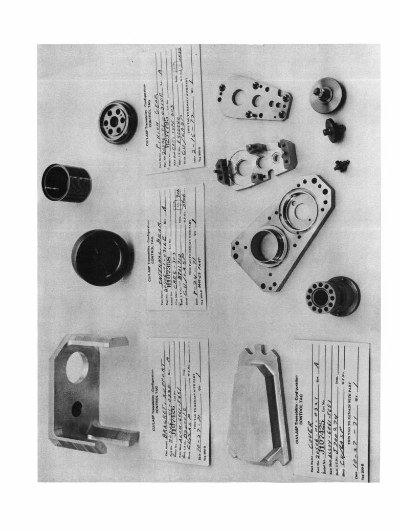
8.0 PHOTOGRAPHS
Several representative photographs of the instrument
are included in this report for informational purposes.
HEIGHT (km)
10in toIO 8
CO
IO
IO(O
IOIO
10
s10CM
10
IO
IOI
IOI
IOCMi
10.roi10
IOIO
UJo
«> CO
tr
UJ
ONO
OUJCO
COCOO01o
<0
oeUJCD2£UJ
OLUJCO
CM
10COI
(8W) 3dOSS3dd
MwniKHW HttUJsfHKttt fmi> tlTT .UP t
OEPAKTMENT OF DEFKN'SE WEATHKII PLOTTING CHAUT
<BOKE MIXING
SEPTEMBER-OCTOBEg 1967
s.o m (llg/g)
. NO. II
U.S. AIR KOUCE \\KATI1KK rU)TTIN(; CIIAKT
OZONE toxine MTIOSEPTEMBER-OCTDBU 1967
5.0 MB (ug/g)
I
MHTIIKHN IIKMIsrHKHK .«*S4»W MM
FIG. NO. 12
AAFE TEST DATA CHARTIN FLIGHT CALIBRATION MONITORS
HVPS-1 (PMT Serial No. 17003)
Level 4 = +2.33V = +2504V ActualLevel 3 = +1.87V = +1987V ActualLevel 2 = +1.58V = +1604V ActualLevel 1 = +1.05V = +1102V ActualOff = +0.10V = + 00V Actual
HVPS-2 (PMT Serial No. 17133)
Level 4 = +2.33V = +2654V ActualLevel 3 = +1.85V = +2092V ActualLevsl 2 = +1.52V = +1656V ActualLevel 1 = +0.99V = +1027V Actual,Off = +0.10V = + 00V Actual'
Channel-1 Cal Lamp
Level 4 22528 CountsLevel 3 3456 CountsLevel 2Level 1
Channel-2 Cal Lamp
Level 4 3712 CountsLevel 3 640 CountsLevel 2Level 1
+10V Monitor
+3.5IV = +10.02 Actual
-10V Monitor
+2.62V = -10.00 Actual
Motor Monitor
+2.00V = 14.00 V RMS Actual
Pre Regulator Monitor
+3.14V Nominal
Main Frame Word 8
32767 Counts
Channel Identifier
0.00V = Word 72 is Channel-24.90V = Word 72 is Channel-1
Channel-1 8c Channel-2 Dark Counts
0 to 4
FIG. NO. 14
o
CO
O
CO
9CcOJCO
0>o>O
CM
4)CcOfO
O«0}2O00
i.
to^*c3Oo1 -(ONCV)to
— CM
oo•o
. ooo\- «o
oo
.CM
o<
—^II-o
UJ_Jtu
w
coo0)
CO
UJ
H
UJ
OorQL
<OV)
O
Q.
10
oz6
o10
inCM
itoCM
o-§
in in
i ' • ' I > !
t tt tmtii Htrmtti
-f ^!iM
I II 1 M.I I'l I.I I II I I I
i l li' I
1.1 I HI I I I I II I I ! I I TIT M M HI M I N NBJ nnn n HI» inn! n n ninn'5-I.U
§
i f
* 3*ii . 5*
! ' '
Mi • K; s• &I £l t wil . ifl " mii ^^___ ^^—
T ii! .. . . :
f "ii M
3s OS? SB 's •*o> «s- ii 55s 35 31 *s< -|.
o3
i
1Js&:•««4
3
I 5-2
°S3si'?;"«gis'Ss'Ss'S
cnrn
rrety
mncp
. n. „,„«,„
, ro
«».i-
ixita
MI
»M v
et.T
«,ac
MM
OU
TPUT
i U
K B
w>
'»•
ro*
*t •
rod ik*
-iv
«to
H
UH
Yot
t»%
i kt
«tv.
» *r
n«
D
tTtK
MiH
iuft
row
k4 .
KK
MOT
> (E
>;
u*»
4W
< '¥
••
ro«.»
a-
kUCf
t »«t
«4
OM
M»,
|w
, SJ
fc-
' fo
2fc
*IA
iuti »
M .m
t»
To
H
V»»>
I »N
O
J» 1
1 k.*
V4U
t3
TO
MV
fl-X
.*»-T
K
it
IBtN
TIC
Ah.
CK
CK
PT P
O*
MO
TtA
. (S
tt
mT
»*C
OM
W«.tT
lOM
O
I»««*M
OO
Ol).
MA
T S
l«—
. .
* '
• .\
»>
o»1
wn
>iM
«m
>,
jfSi '|j« ' "
-! Jrt ic« '• « - y-» i .-i r 1 1 » "mj *^
s«
nii
*«S'"
f J4
til1_J-
s4
r«» f i -, •^ ,****
fclY-Jrs istn ra 1- s ?s55 «»Sl 51 1
13* f| IIS zVi •
5> . l«ar iii- fcj 4__.-T^/K^
T'l 4«.v—— i• M 1
111 1 l' I
J' 1 ^u = 1 ..N °. .'
«« ^VW.4 srsstsiLl5.-S, . • „• rj-1 )<]
n J'' n* *ir ••a - 1 1
ix5
§i
-2i
S1
s*ssJLr5 :A~ |
s,?= :tiS s « £
— ( Jx '•>%> —tflT
!
Ill
» <0
5 S
S «S =
r " » 2 * 1 S < / \ L ttl- •
{«•l§
\
..i!ij
*i!«
1.,-.
ii|
iii<
SC
HE
MM
IC D
lkG
R\M
'
GH
V
OLT
A&
t K
WJt
R S
UP
^Y
1
n•
k
, IH
3-2
050fe
-02-0
20J
! 11 ..-
.H
* IC
»L ; ,
S v8|0 i
iiulii. 1'---- |t| f i«:;•>; 'I * (I
S'HB!i illiif!
»lH$
is-
i
1 5 .
rt
* • < >-
i j ?MMJ»J i s f S J J 2 Si 2 S s l i S s J f • : s 5 - H ' S js 2 32 S S :|Ai J s S . ;3 •• •* « 3 "ia* I J -3I AA «A .
-
GENERAL NOTES UNLESS OTHERWISE SPECIFIEDI. RESISTORS ARE IOOK, TYPE RCOT
2.DIODES ARE TYPE IN4454
3.REF OES R9 NOT USED
1 fu> I Mai
OPTIONALCOMMAND LO/Mf
~i~r~i
tft DKTA MONITOR MT.
. iivsro HPUTS
CL ~»
•40M CcnNTCT ml I»|*<u ot/«o unirj TO ua
nrr:
IS of 'maK'
LOGIC DIAGRAM
LOGIC MODULE
28981 5-20506-02-050I
4
L" V " *Vi JK!
H '
*J
•I
1 1
•8
jr
N -'i J z
^ !a •»Lfpupij£
if. t^v/
s<.
/
i>,"•
.
M
ll
n;
JM
^2<
;
E
1X >t 9
•
M>n <Ni iI Ji ••A *
i• V
Ik
l1i
i i!u 1 i j
ti ' s »
S5
I l l l l v j11
mi
f »•5 »•
1 NJ
£ r\
I1,