81
MAINTENANCE MANUAL RELEASE: February 2007 Part Number: 90313
| Date post: | 26-Oct-2015 |
| Category: |
Documents |
| Upload: | stainless31620039126 |
| View: | 71 times |
| Download: | 1 times |

MAINTENANCEMANUAL
RELEASE: February 2007 Part Number: 90313

FOREWORD
Here is the new Labrie parts and maintenance manual for theOPTIMIZERTM front loading unit. We sincerely hope that youwill find it easy to use.
We have designed it in a way that will allow you to easily make itavailable to drivers, mechanics, and to parts department personnel.
Any time that you have a problem with a Labrie unit, you shouldcontact your vendor first. He should be able to provide you with theproper help required (parts or technical advice).
FIRST THINGS FIRST:
DO NOT FORGET TO COMPLETE THE OWNERREGISTRATION FORM AND TO SEND IT TO LABRIEEQUIPMENT, MAKING SURE TO INDICATE “IN SERVICEDATE”. THIS DATE WILL BE USED TO START THEWARRANTY PERIOD. OTHERWISE, THE DATE OFDELIVERY FROM THE FACTORY WILL BE USED.

OPTIMIZERTM
4

5
MAINTENANCE
OPTIMIZERTM
MAINTENANCE MANUAL
Table of contents
1.0 MAINTENANCE MANUAL .................................................................................... 9
2.0 LUBRICATION.................................................................................................... 33
3.0 TROUBLESHOOTING SECTION ...................................................................... 39
4.0 OPTIMIZER BODY PARTS ................................................................................ 49
5.0 HYDRAULIC SYSTEMS, PARTS AND DIAGRAMS ........................................... 65
6.0 BODY AIR SYSTEMS, PARTS AND DIAGRAMS............................................... 93
7.0 ELECTRICAL SYSTEMS DIAGRAMS AND PARTS .......................................... 99
OPTIMIZERTM
6
OPTIMIZERTM
CHAPTER 1.0
Table of contents
1.0 MAINTENANCE MANUAL .................................................................................... 91.1 GENERAL SAFETY PRECAUTIONS ..................................................................... 9
1.1.1 GENERAL PRECAUTION ..................................................................................... 91.1.2 SURFACE FINISHING AND PAINT ..................................................................... 101.1.3 FIRE PROTECTION .......................................................................................... 101.1.4 LOCKOUT / TAGOUT PROCEDURE ................................................................... 101.1.5 SHUTDOWN PROCEDURE ................................................................................ 111.1.6 PRIOR TO START UP .......................................................................................... 111.1.7 HYDRAULIC FILTER FIRST REPLACEMENT .................................................... 121.1.8 GENERAL CLEANLINESS ................................................................................. 121.1.9 CLEANING THE HOPPER AREA........................................................................ 121.1.9A BODY HOISTING ............................................................................................... 131.1.10 PROPPING PROCEDURES ............................................................................... 15
1.2 PACKING SYSTEM MAINTENANCE ................................................................. 161.2.1 PACKING SYSTEM GENERAL MAINTENANCE ................................................. 161.2.2 PROXIMITY SWITCHES ADJUSTMENT ............................................................ 161.2.3 PACKER BLADE WEAR PLATES REPLACEMENT ........................................... 181.2.4 BODY GUIDE WEAR PLATES REPLACEMENT ................................................ 191.2.5 PACKER BLADE REMOVAL PROCEDURE ....................................................... 201.2.6 PACKER CYLINDERS REPLACEMENT ............................................................. 211.2.7 LUBRICATION OF PACKING SYSTEM .............................................................. 21
1.3 TAILGATE SYSTEM AND BODY HINGES MAINTENANCE ................................ 221.3.1 TAILGATE LOCKING MECHANISM .................................................................... 221.3.2 TAILGATE SEAL AND HINGES INSPECTION .................................................... 231.3.3 REAR BODY HINGE INSPECTION .................................................................... 231.3.4 PROXIMITY SWITCHES ON TAILGATE ............................................................. 231.3.5 HOPPER DOOR SENSOR .................................................................................. 241.3.6 ROOF PROXIMITY SWITCH .............................................................................. 241.3.7 FORKS AND ARMS PROXIMITY SWITCHES .................................................... 241.3.8 ARMS PARTLY RAISED PROXIMITY SWITCH .................................................. 251.3.9 PROXIMITY SWITCH ADJUSTMENT ................................................................. 25
7
MAINTENANCE
OPTIMIZERTM
CHAPTER 1.0
Table of contents
1.4 HYDRAULIC SYSTEM MAINTENANCE .............................................................. 261.4.1 HYDRAULIC SYSTEM GENERAL INSPECTION ................................................ 261.4.2 MAIN RELIEF VALVE PRESSURE ADJUSTMENT ............................................. 261.4.3 HYDRAULIC DIRECTIONAL CONTROL VALVE ................................................. 271.4.4 PRESSURE ADJUSTMENT PROCEDURE ......................................................... 281.4.5 PUMP MAINTENANCE ....................................................................................... 281.4.6 HYDRAULIC CYLINDERS INSPECTION PROCEDURES .................................. 291.4.7 HYDRAULIC RESERVOIR INSPECTION PROCEDURE .................................... 291.4.8 HYDRAULIC FLUID REPLACEMENT PROCEDURE .......................................... 301.4.9 HYDRAULIC FILTER REPLACEMENT PROCEDURE ........................................ 321.4.10 HYDRAULIC STRAINER CLEANING PROCEDURE ........................................... 321.4.11 TAILGATE HYDRAULIC SYSTEM MAINTENANCE ............................................ 331.4.12 CYCLE TIME TABLE FOR ALL HYDRAULIC FUNCTIONS ................................. 331.4.12 BODY HOISTING SYSTEM MAINTENANCE ...................................................... 331.4.13 ARMS UP DECELERATION VALVE .................................................................. 361.4.14 ARMS DOWN DECELERATION VALVE ............................................................ 38
1.5 AIR SYSTEM MAINTENANCE ............................................................................. 391.5.1 AIR SYSTEM MAINTENANCE PROCEDURE ..................................................... 39


9
MAINTENANCE
WARNING
PERSONNEL IN CHARGE OFMAINTENANCE SHALL NOTPERFORM ANY MAINTENANCEON THE EQUIPMENT WITHOUTKNOWING THE PROPEROPERATIONS OF THEEQUIPMENT AS WELL AS ALLSAFETY PRECAUTIONS OF SUCHOPERATIONS. REFER TO THEOPERATION MANUAL PRIOR TOPERFORM ANY TYPE OF WORKON THE UNIT.
For maintenance of the truck itself, please referto the chassis maintenance manual. Only thebody section and its components will beaddressed in this manual.
Establish and apply a periodic inspection programto keep the moving parts in good working order,properly adjusted and safe. It is recommendedthat a brief inspection is done by the operatorEVERY DAY and that any problems or detectedmalfunctions is reported for correction beforereusing the equipment.
Once a month, inspect the chassis and the bodyfor any breaks, cracks or possible malfunctions.Any defects found must be repaired withoutdelay. To assure good working order of theequipment, particular attention should be paid tothe deterioration of structural components due tocorrosion. Touch-ups or complete paint jobsshould be done when necessary.
MAINTENANCE AND REPAIRSCARRIED OUT ON THIS VEHICLE,MUST BE ONLY DONE BYQUALIFIED PERSONNEL WHOARE FAMILIAR WITH THISEQUIPMENT. LABRIEENVIRONMENTAL GROUP IS NOTRESPONSIBLE FOR ANYFAILURES RESULING OF REPAIRSPERFORM BY THE USER.
BEFORE DOING ANYMAINTENANCE WORK ON THEVEHICLE, ALL SAFETYREGULATIONS MENTIONED INTHE OPERATOR MANUAL, MUSTBE RESPECTED, ESPECIALLY THE“ L O C K O U T / T A G O U T ”PROCEDURE (ANSI Z 245.1 1984).
CAUTION
CAUTION
1.0 MAINTENANCE MANUAL
1.1 GENERAL SAFETYPRECAUTIONS
1.1.1 GENERAL PRECAUTION
OPTIMIZERTM
10
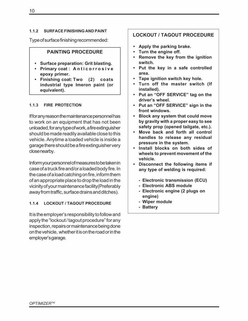
1.1.3 FIRE PROTECTION
If for any reason the maintenance personnel hasto work on an equipment that has not beenunloaded, for any type of work, a fire extinguishershould be made readily available close to thisvehicle. Anytime a loaded vehicle is inside agarage there should be a fire extinguisher veryclose nearby.
Inform your personnel of measures to be taken incase of a truck fire and/or a loaded body fire. Inthe case of a load catching on fire, inform themof an appropriate place to drop the load in thevicinity of your maintenance facility(Preferablyaway from traffic, surface drains and ditches).
1.1.4 LOCKOUT / TAGOUT PROCEDURE
It is the employer’s responsibility to follow andapply the “lockout / tagout procedure” for anyinspection, repairs or maintenance being doneon the vehicle, whether it is on the road or in theemployer’s garage.
PAINTING PROCEDURE
• Surface preparation: Grit blasting.• Primary coat : A n t i c o r r o s i v e
epoxy primer.• Finishing coat: Two (2) coats
industrial type Imeron paint (orequivalent).
Type of surface finishing recommended:
1.1.2 SURFACE FINISHING AND PAINTLOCKOUT / TAGOUT PROCEDURE
• Apply the parking brake.• Turn the engine off.• Remove the key from the ignition
switch.• Put the key in a safe controlled
area.• Tape ignition switch key hole.• Turn off the master switch (If
installed).• Put an “OFF SERVICE” tag on the
driver’s wheel.• Put an “OFF SERVICE” sign in the
front windows.• Block any system that could move
by gravity with a proper easy to seesafety prop (opened tailgate, etc.).
• Move back and forth all controlhandles to release any residualpressure in the system.
• Install blocks on both sides ofwheels to prevent movement of thevehicle.
• Disconnect the following items ifany type of welding is required:
- Electronic transmission (ECU)- Electronic ABS module- Electronic engine (2 plugs on
engine)- Wiper module- Battery
11
MAINTENANCE
SHUT DOWN PROCEDURE
• Park on a hard level surface.• Apply parking brake.• Make sure that all moving parts are
in the storage position (tailgate,arms and forks, packer, etc).
• Turn hydraulics, electricals andengine off.
• Turn the master switch off (ifequipped).
• Empty air tanks.
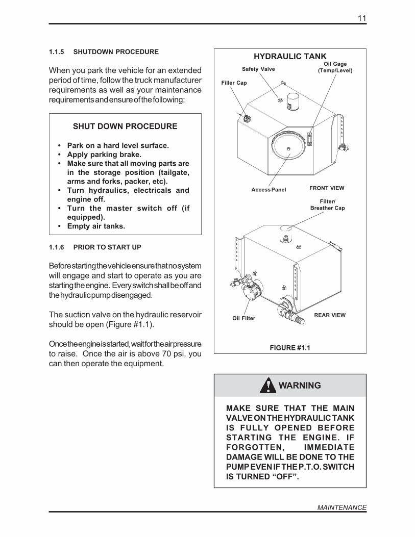
1.1.6 PRIOR TO START UP
Before starting the vehicle ensure that no systemwill engage and start to operate as you arestarting the engine. Every switch shall be off andthe hydraulic pump disengaged.
The suction valve on the hydraulic reservoirshould be open (Figure #1.1).
Once the engine is started, wait for the air pressureto raise. Once the air is above 70 psi, youcan then operate the equipment.
Oil Filter
Filler Cap
HYDRAULIC TANK1.1.5 SHUTDOWN PROCEDURE
When you park the vehicle for an extendedperiod of time, follow the truck manufacturerrequirements as well as your maintenancerequirements and ensure of the following:
FIGURE #1.1
Access Panel
WARNING
MAKE SURE THAT THE MAINVALVE ON THE HYDRAULIC TANKIS FULLY OPENED BEFORESTARTING THE ENGINE. IFFORGOTTEN, IMMEDIATEDAMAGE WILL BE DONE TO THEPUMP EVEN IF THE P.T.O. SWITCHIS TURNED “OFF”.
FRONT VIEW
REAR VIEW
Oil Gage(Temp/Level)
Filter/Breather Cap
Safety Valve

OPTIMIZERTM
12
WARNING
TO PROTECT THE NEWCOMPONENTS, THE RETURNFILTER MUST BE CHANGEDAFTER THE FIRST 50 HOURS OFUSE. SEE HYDRAULIC FILTERREPLACEMENT PROCEDURE INSECTION 1.4.8.
BEFORE STARTING THE ENGINE,MAKE SURE THAT THE SUCTIONVALVE ON THE RESERVOIR ISCOMPLETELY OPEN (FIGURE#1.1). IF THE VALVE IS CLOSED,IMMEDIATE DAMAGE WILLOCCUR TO THE PUMP EVEN IFTHE P.T.O. SWITCH IS TURNED“OFF”.
1.1.9 CLEANING THE HOPPER AREA
The area behind the packer should be cleanedevery day. The packer will not work properly ifthe waste accumulates in this area, it could evencause severe damage to the packer and otheradjacent systems.
CAUTION
DANGER
PROPERLY APPLY THELOCKOUT/TAGOUT PROCEDURETO PREVENT ANY ACCIDENTALRESTARTING OF THE ENGINE.(REFER TO THE LOCKOUT /TAGOUT PROCEDURE SECTION1.1.4)
1.1.7 HYDRAULIC FILTER FIRSTREPLACEMENT
1.1.8 GENERAL CLEANLINESS
Cleanliness is part of safety. Make sure thatthe equipment is kept in proper workingorder by removing any stacked garbage inthe packer area. Keep clean all the trucklights, warning lights and safety stickers sothe driver, the surrounding pedestrians andvehicles will be safe around the truck at alltimes.
HOPPER CLEANING PROCEDURE
• Turn on the engine and the hydraulicsystem.
• Open the hopper roof gate.
• Remove the tailgate safety pins.
• Fully open the tailgate. A green lighton the console turns on to promptyou about it.
• Press and hold the green button onthe console to move the packer allthe way to the end of its stroke.
• Apply the Lockout/Tagoutprocedure (see section 1.1.4).
• Open the hopper door on the rightside of the body.
• Get in the hopper area and removeany residual material. Use a highpressure water jet to complete thecleaning. Never close the hopperdoor behind you while you are insidethe hopper area.
• Get off the vehicle and close thehopper door.
• Back in the cab, turn on the engineand the hydraulic system.
13
MAINTENANCE
HOPPER CLEANING PROCEDURE(cont’d)
• Press and hold the yellow button onthe console to retract the packer toits home position.
• Close the tailgate, turn off theengine, and put the safety pins backinto place.
• Close the hopper roof gate.
DANGER
NEVER CLOSE THE HOPPERDOOR BEHIND YOU WHILE YOUARE INSIDE THE HOPPER AREA.
1.1.9A BODY HOISTING
Some units are equippes with a body hoistingsystem to facilitate the maintenance underthe body.If your unit is equipped with this system,perform the following steps to lift the body:
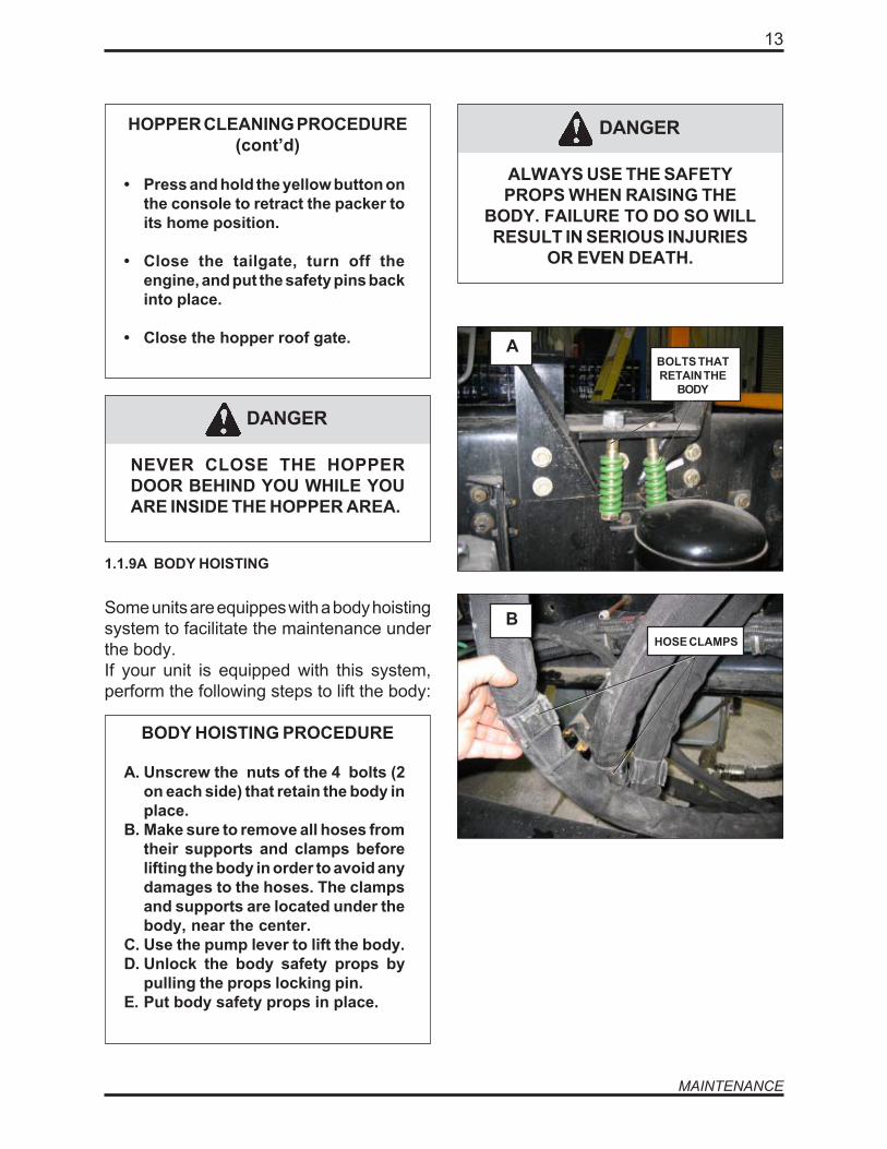
BODY HOISTING PROCEDURE
A. Unscrew the nuts of the 4 bolts (2on each side) that retain the body inplace.
B. Make sure to remove all hoses fromtheir supports and clamps beforelifting the body in order to avoid anydamages to the hoses. The clampsand supports are located under thebody, near the center.
C. Use the pump lever to lift the body.D. Unlock the body safety props by
pulling the props locking pin.E. Put body safety props in place.
DANGER
ALWAYS USE THE SAFETYPROPS WHEN RAISING THE
BODY. FAILURE TO DO SO WILLRESULT IN SERIOUS INJURIES
OR EVEN DEATH.
BOLTS THATRETAIN THE
BODY
HOSE CLAMPS
A
B

OPTIMIZERTM
14
DANGER
NEVER GO UNDER THE BODYWHEN THE SAFETY PROPS ARENOT INSTALLED. FAILURE TO
DO SO WILL RESULT INSERIOUS INJURIES OR EVEN
DEATH.
PUT THE BODYSAFETY
PROPS INPLACE
SAFETYPROPS
LOCKING PIN
USE THEPUMP LEVERTO LIFT THE
BODY
D
C E
CLAMPSLOCATED
UNDER THEBODY, NEARTHE CENTER

15
MAINTENANCE
DANGER
FIGURE #1.2
FIGURE #1.3
1.1.10 PROPPING PROCEDURES
NEVER WORK UNDER, OR CLOSETO EQUIPMENT OR ANY PARTTHAT IS NOT SAFELY PROPPEDOR SECURED.
ALWAYS USETHE PROVIDEDSTEP LADDERS (OR ANY OTHERSAFE LADDER TO WORKTOWARDS THE FRONT) TO GETON THE ROOF OR TO WORK ONHIGHER PARTS OF THEEQUIPMENT. REMEMBER THATTHE ROOF IS NOT MEANT TO BEWALKED UPON. BE VERYCAUTIOUS IF YOU HAVE TOWORK ON THE ROOF AREA.
ALWAYS FOLLOW PROPERLOCKOUT/TAGOUT PROCEDURE(SECTION 1.1.4).
CLEANING BEHINDTHE PACKER BLADE
HOPPER DOOR
ALWAYS USE THE TAILGATESAFETY PROP WHEN WORKINGUNDER A RAISED TAILGATE.PROP CAN BE INSTALLED EVENIF THE TAILGATE HAS TO BE INIT’S FULLY RAISED POSITION.
The tailgate has its own safety prop system. Theprop is installed when the tailgate is slightlyopen. The tailgate, when open, should alwaysrest against the safety prop.
DANGER
OPTIMIZERTM
16
1.2 PACKING SYSTEMMAINTENANCE
1.2.1 PACKING SYSTEM GENERALMAINTENANCE
The OPTIMIZERTM packing system has anheavy duty guiding system using specialhardened steel wear plates. However,because of the frequent use of the ram, werecommend that daily visual inspections beperformed by the operator and weeklyinspections by the maintenance personnel.
Greasing all moving parts on a daily basis is veryimportant. The proper adjustment of theproximity switches is also very important.
Any problem must be corrected immediately.The factory service departement is available forany support you may require.
1.2.2 PROXIMITY SWITCHES ADJUSTMENT
The proximit switches were properly adjustedat the factory. However, if the cleaning behindthe packer is not performed daily, it is possiblethat the proximity switches will no longer stopthe packer automatically. An accumulation ofdirt behind the packer prevent it to retract farenough to activate the proximity switch.
Also, after a certain period of time, it mightbe necessary to adjust the proximity switches,to prevent the cylinders from completelyretracting (or extending) to the end of theirstroke.
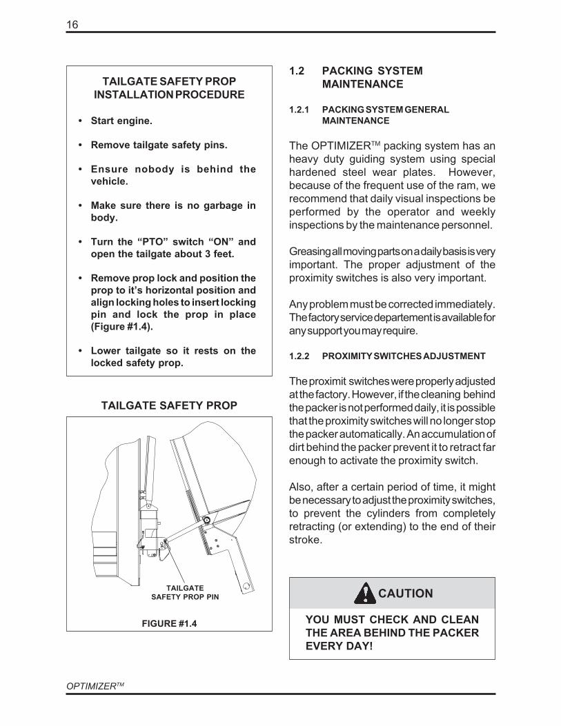
FIGURE #1.4
TAILGATE SAFETY PROP
TAILGATESAFETY PROP PIN
TAILGATE SAFETY PROPINSTALLATION PROCEDURE
• Start engine.
• Remove tailgate safety pins.
• Ensure nobody is behind thevehicle.
• Make sure there is no garbage inbody.
• Turn the “PTO” switch “ON” andopen the tailgate about 3 feet.
• Remove prop lock and position theprop to it’s horizontal position andalign locking holes to insert lockingpin and lock the prop in place(Figure #1.4).
• Lower tailgate so it rests on thelocked safety prop.
YOU MUST CHECK AND CLEANTHE AREA BEHIND THE PACKEREVERY DAY!
CAUTION

17
MAINTENANCE
ADJUSTING THE PROXIMITYSWITCHES
• Move the packer blade about 1 inchback from the fully extendedposition.
• Adjust the proximity switch #1 so itis “active” (the amber light on theproximity switch should be ON)when the packer blade reaches thisposition.
• Apply the same procedure for theretracted position (proximity switch#2).
• Test the packer for a full cycle.Ensure that there is no knockingnoise at the end of the packercylinder strokes.
PROXIMITY SWITCHES LOCATION
USE THE APPROPRIATELOCKOUT/TAGOUT PROCEDUREAT ALL TIMES (SECTION 1.1.4).
DANGER
FIGURE #1.5
Proximity switches
1.2.2 PROXIMITY LIMIT SWITCHESADJUSTMENT (continued)

OPTIMIZERTM
18
1.2.3 PACKER BLADE WEAR PLATESREPLACEMENT
If the packer blade has a vertical movementgreater than 3/16 or a side movement greaterthan 1/8; verify the wear plates and the bodyguide.
We use two different types of steel for wearplates:The “AR 425” and the “AR 500”.
PACKER BLADE WEAR PLATES
FIGURE #1.6
REPLACING PACKER BLADEWEAR PLATES
• Remove packer blade (refer topacker blade removal procedure,Sec. 1.2.5)
• Remove the packer blade wearplates from packer blade (Figure#1.6).
• Verify corresponding wear platesunder guiding tracks (Figure #1.7).
• Install new packer blade wear plateson packer blade
• Reinstall packer blade on unit (referto packer blade removal procedure,Sec. 1.2.5).
Packer bladewear plates
USE THE APPROPRIATELOCKOUT/TAGOUT PROCEDUREAT ALL TIMES (SECTION 1.1.4).
DANGER

19
MAINTENANCE
1.2.4 BODY GUIDE WEAR PLATESREPLACEMENT
BODY GUIDE WEAR PLATESREPLACEMENT PROCEDURE
• Remove the packer blade (refer topacker blade removal procedure,Sec. 1.2.5 ).
• Retract the packing cylinders andmove them out of the way.
• Remove body wear plates bygrinding or cutting the stitch weldsattaching plates to guide.
• Clean surfaces and position newplates by tacking them in place.
• Once in proper position stitch weldplates in place.
• Reinstall packer blade.
BODY GUIDE WEAR PLATES
Body guide wear plates
USE THE APPROPRIATELOCKOUT/TAGOUT PROCEDUREAT ALL TIMES (SECTION 1.1.4).
FIGURE #1.7
DANGER
OPTIMIZERTM
20
1.2.5 PACKER BLADE REMOVALPROCEDURE
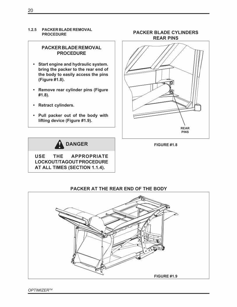
PACKER BLADE REMOVALPROCEDURE
• Start engine and hydraulic system.bring the packer to the rear end ofthe body to easily access the pins(Figure #1.8).
• Remove rear cylinder pins (Figure#1.8).
• Retract cylinders.
• Pull packer out of the body withlifting device (Figure #1.9).
FIGURE #1.8
PACKER BLADE CYLINDERSREAR PINS
FIGURE #1.9
PACKER AT THE REAR END OF THE BODY
REARPINS
USE THE APPROPRIATELOCKOUT/TAGOUT PROCEDUREAT ALL TIMES (SECTION 1.1.4).
DANGER

21
MAINTENANCE
CAUTION
BECAUSE OF IT’S FREQUENTUSE, THE PACKER AND IT'SACCESSORIES MUST BELUBRICATED EVERY WORKINGDAY.
1.2.7 LUBRICATION OF PACKING SYSTEM
Refer to the chapter 5 on lubrication for:• Cylinder pins (Figure #1.10)• Door hinges.
1.2.6 PACKER CYLINDERS REPLACEMENT
PACKER CYLINDERREPLACEMENT PROCEDURE
• Extend the packer blade completely.
• Remove cylinder rear pins (Figure#1.8).
• Retract the cylinders.
• Remove hoses from cylinders andfront pins.
• Reverse procedure for installation.
FIGURE #1.10
GREASE FITTINGS
SUPPORT THE CYLINDER TO BEREMOVED WITH PROPERLIFTING DEVICE.
Greasefittings
USE THE APPROPRIATELOCKOUT/TAGOUT PROCEDUREAT ALL TIMES (SECTION 1.1.4).
CAUTION
DANGER
OPTIMIZERTM
22
CAUTION
1.3.1 TAILGATE LOCKING MECHANISM
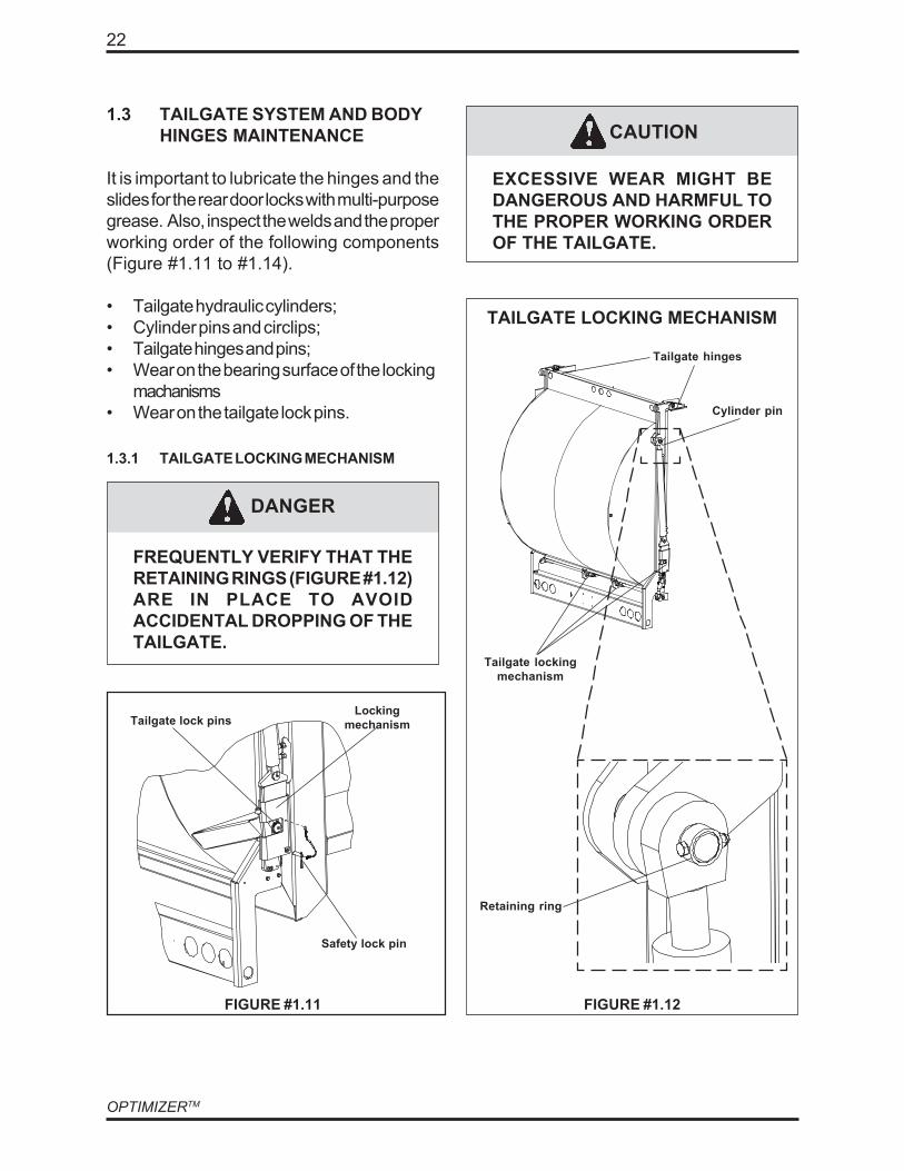
1.3 TAILGATE SYSTEM AND BODYHINGES MAINTENANCE
It is important to lubricate the hinges and theslides for the rear door locks with multi-purposegrease. Also, inspect the welds and the properworking order of the following components(Figure #1.11 to #1.14).
• Tailgate hydraulic cylinders;• Cylinder pins and circlips;• Tailgate hinges and pins;• Wear on the bearing surface of the locking
machanisms• Wear on the tailgate lock pins.
FREQUENTLY VERIFY THAT THERETAINING RINGS (FIGURE #1.12)ARE IN PLACE TO AVOIDACCIDENTAL DROPPING OF THETAILGATE.
FIGURE #1.11 FIGURE #1.12
TAILGATE LOCKING MECHANISM
EXCESSIVE WEAR MIGHT BEDANGEROUS AND HARMFUL TOTHE PROPER WORKING ORDEROF THE TAILGATE.
Cylinder pin
Tailgate hinges
Tailgate lockingmechanism
Retaining ring
DANGER
LockingmechanismTailgate lock pins
Safety lock pin

23
MAINTENANCE
1.3.2 TAILGATE SEAL AND HINGESINSPECTION
The hinge pins must not have any signs ofexcessive wear or metal fatigue. The retainingbolts must be kept tight (Figure #1.15).Perform a visual inspection of the rubber sealalong the rim of the tailgate. Replace anybroken components necessary
1.3.3 REAR BODY HINGE INSPECTION
Monthly lubrication of the body and chassishinges should be done (Figure #1.13). Also,inspect for cracks or corrosion. Any eventualcracks must be reported, recorded and repairedby qualified personnel.
1.3.4 PROXIMITY SWITCHES ON TAILGATE
The unit has a proximity switch that activatesthe back-up alarm and a warning buzzer(inside the cab) to tell the operator that thetailgate is unlocked (Figure #1.15). Aproximity switch (Figure #1.14), mounted ontop of the body will engage a light on theconsole to warn the operator that the tailgateis fully opened. Verify the proper workingorder and adjustment of those two limitswitches.
FIGURE #1.15
PROXIMITY SWITCH FORUNLOCKED TAILGATE
FIGURE #1.14
Limit switch
Tailgate
PROXIMITY SWITCH FOR FULLYRAISED TAILGATE
CHASSIS HINGE
FIGURE #1.13
Proximity switch
OPTIMIZERTM
24
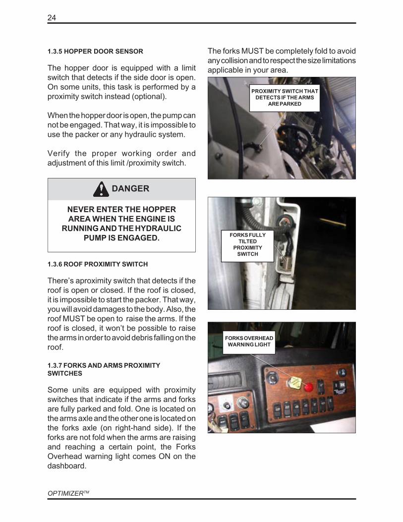
1.3.5 HOPPER DOOR SENSOR
The hopper door is equipped with a limitswitch that detects if the side door is open.On some units, this task is performed by aproximity switch instead (optional).
When the hopper door is open, the pump cannot be engaged. That way, it is impossible touse the packer or any hydraulic system.
Verify the proper working order andadjustment of this limit /proximity switch.
NEVER ENTER THE HOPPERAREA WHEN THE ENGINE IS
RUNNING AND THE HYDRAULICPUMP IS ENGAGED.
DANGER
1.3.6 ROOF PROXIMITY SWITCH
There’s aproximity switch that detects if theroof is open or closed. If the roof is closed,it is impossible to start the packer. That way,you will avoid damages to the body. Also, theroof MUST be open to raise the arms. If theroof is closed, it won’t be possible to raisethe arms in order to avoid debris falling on theroof.
1.3.7 FORKS AND ARMS PROXIMITYSWITCHES
Some units are equipped with proximityswitches that indicate if the arms and forksare fully parked and fold. One is located onthe arms axle and the other one is located onthe forks axle (on right-hand side). If theforks are not fold when the arms are raisingand reaching a certain point, the ForksOverhead warning light comes ON on thedashboard.
The forks MUST be completely fold to avoidany collision and to respect the size limitationsapplicable in your area.
PROXIMITY SWITCH THATDETECTS IF THE ARMS
ARE PARKED
FORKS OVERHEADWARNING LIGHT
FORKS FULLYTILTED
PROXIMITYSWITCH
25
MAINTENANCE
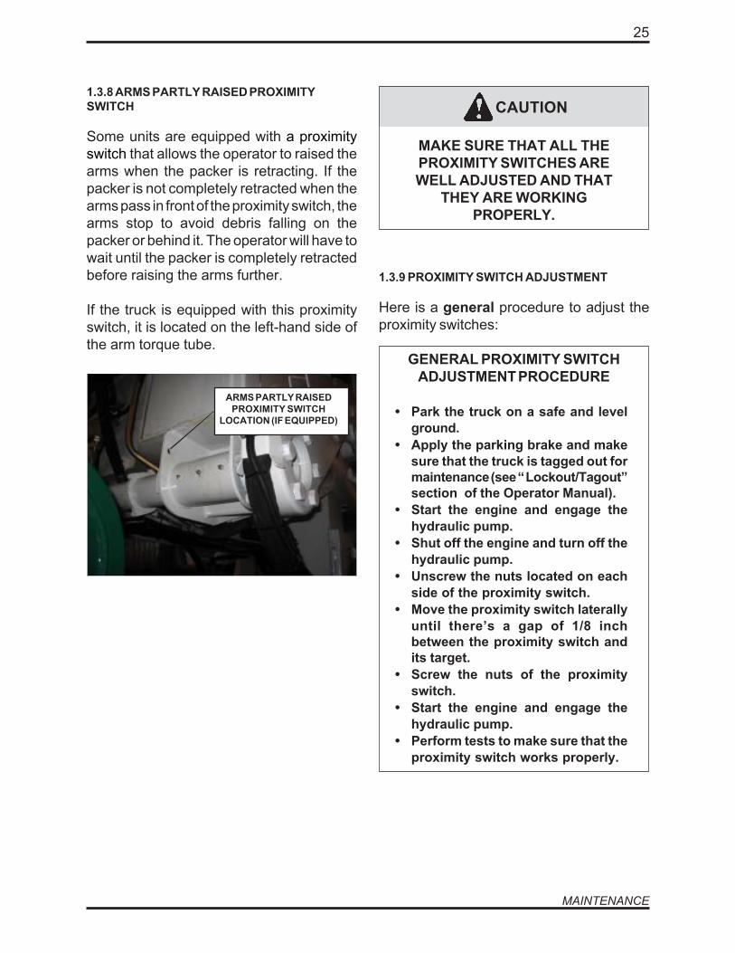
1.3.8 ARMS PARTLY RAISED PROXIMITYSWITCH
Some units are equipped with a proximityswitch that allows the operator to raised thearms when the packer is retracting. If thepacker is not completely retracted when thearms pass in front of the proximity switch, thearms stop to avoid debris falling on thepacker or behind it. The operator will have towait until the packer is completely retractedbefore raising the arms further.
If the truck is equipped with this proximityswitch, it is located on the left-hand side ofthe arm torque tube.
CAUTION
MAKE SURE THAT ALL THEPROXIMITY SWITCHES AREWELL ADJUSTED AND THAT
THEY ARE WORKINGPROPERLY.
1.3.9 PROXIMITY SWITCH ADJUSTMENT
Here is a general procedure to adjust theproximity switches:
GENERAL PROXIMITY SWITCHADJUSTMENT PROCEDURE
• Park the truck on a safe and levelground.
• Apply the parking brake and makesure that the truck is tagged out formaintenance (see “ Lockout/Tagout”section of the Operator Manual).
• Start the engine and engage thehydraulic pump.
• Shut off the engine and turn off thehydraulic pump.
• Unscrew the nuts located on eachside of the proximity switch.
• Move the proximity switch laterallyuntil there’s a gap of 1/8 inchbetween the proximity switch andits target.
• Screw the nuts of the proximityswitch.
• Start the engine and engage thehydraulic pump.
• Perform tests to make sure that theproximity switch works properly.
ARMS PARTLY RAISEDPROXIMITY SWITCH
LOCATION (IF EQUIPPED)

OPTIMIZERTM
26
1.4 HYDRAULIC SYSTEMMAINTENANCE
1.4.1 HYDRAULIC SYSTEM GENERALINSPECTION
HYDRAULIC SYSTEM GENERALINSPECTION PROCEDURE
• For new equipment, change thereturn element filter after 50 hoursof use, and every 500 hoursthereafter. See hydraulic filterreplacement procedure section1.4.9;
• Clean the strainer inside thereservoir after the first 50 hours ofuse and yearly thereafter (Figure#1.16). See hydraulic strainercleaning procedure, sec.1.4.10;
• When maintenance is carried out,protect the hoses from any dirt thatwould eventually get into the oil;
• Periodically inspect and adjust theoil pressure in the hydraulic systemas follows: 2500 PSI +/- 25 PSI@1500RPM (2300PSI@700 RPM; idlespeed);
• Frequently inspect the hydrauliclines and connections for leaks,correct if necessary;
• The suction valve on the reservoirmust be fully open (Figure #1.1)before starting the engine;
Filter/breather
Fillercap
FIGURE #1.16
HYDRAULIC TANK PARTS
Filter
1.4.2 MAIN RELIEF VALVE PRESSUREADJUSTMENT
A hydraulic oil pressure verification must beperformed every month. The relief valve ispreset to 2500 PSI +/- 50 PSI at 1500 RPMby the manufacturer. If the pressure is notwithin this preset adjustment, the pressurerelief valve must be readjusted.
ADJUSTING THE MAIN RELIEFVALVE AT HIGHER PRESSURETHAN 2500 PSI WILL CREATEEXTENSIVE DAMAGE AND VOIDTHE MANUFACTURER’SWARRANTY.
CAUTION
27
MAINTENANCE
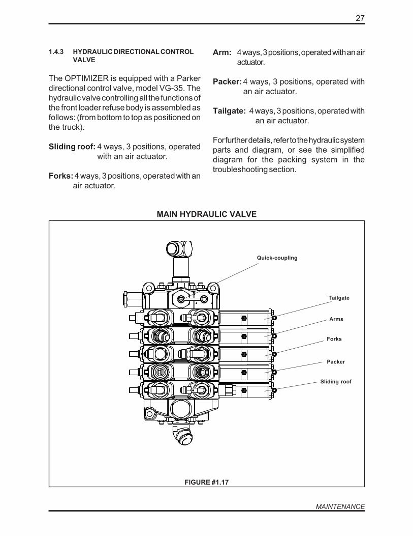
1.4.3 HYDRAULIC DIRECTIONAL CONTROLVALVE
The OPTIMIZER is equipped with a Parkerdirectional control valve, model VG-35. Thehydraulic valve controlling all the functions ofthe front loader refuse body is assembled asfollows: (from bottom to top as positioned onthe truck).
Sliding roof: 4 ways, 3 positions, operatedwith an air actuator.
Forks: 4 ways, 3 positions, operated with anair actuator.
MAIN HYDRAULIC VALVE
Sliding roof
Arm: 4 ways, 3 positions, operated with an airactuator.
Packer: 4 ways, 3 positions, operated withan air actuator.
Tailgate: 4 ways, 3 positions, operated withan air actuator.
For further details, refer to the hydraulic systemparts and diagram, or see the simplifieddiagram for the packing system in thetroubleshooting section.
FIGURE #1.17
Forks
Arms
Packer
Tailgate
Quick-coupling

OPTIMIZERTM
28
PRESSURE ADJUSTMENTPROCEDURE
• Install a 3000PSI pressure gaugeon the quick coupling found on themain valve (Figure #1.17).
• Start the engine and engage thehydraulic system. Maintain theengine speed at 1500 RPM.
• Open the tailgate until themechanism reaches the end of itsstroke.
• Check the pressure while thetailgate is held fully open.
• The pressure reading shall be within2450 and 2550 PSI. Adjust the mainrelief if necessary (Figure #1.17).
• Loosen the lock-nut and turn theadjustment knob clockwise toincrease the pressure and counter-clockwise to reduce the pressure.
USE THE APPROPRIATELOCKOUT/TAGOUT PROCEDUREAT ALL TIMES (SECTION 1.1.4).
1.4.5 PUMP MAINTENANCE
The hydraulic pump on the OPTIMIZERTM isa gear pump type equipped with a Muncielive pack pump (Figure #1.18).
DANGER
1.4.4 PRESSURE ADJUSTMENTPROCEDURE
If the pump is properly maintained, it willprovide a satisfactory output. If the pump isnoisy, carry out the following inspections:
FIGURE #1.18
29
MAINTENANCE
1.4.6 HYDRAULIC CYLINDERS INSPECTIONPROCEDURES
To maintain proper working order and prolongedcylinder performance, it is essential to inspectthem at least once a week as recommended.
Verify that all the connections of the flexiblehoses and pipes are tight, and that there are noexternal leaks.
Check that all the cylinder head cap screws arefirmly tightened and that there are no leaks.All leaks must be corrected immediately byreplacing damaged or worn seals with newones. Lubricate and inspect all the cylindermounting points (pins, retaining bolts, etc.).
1.4.7 HYDRAULIC RESERVOIR INSPECTIONPROCEDURE
Verify that the oil in the reservoir is clean andalways at the proper level.
HYDRAULIC RESERVOIRMAINTENANCE PROCEDURE
• For increased longevity, clean thestrainer inside the reservoir afterthe first 50 hours of service andannually thereafter (Figure #1.16).
• Verify the cleanliness of the fillercap (NOT BLOCKED, Figure #1.16).
• Verify the cleanliness, the color andthe level of the hydraulic oil. (levelat 3/4 of the oil level gauge, with allcylinders retracted).
MAXIMUM TEMPERATURE FORHYDRAULIC FLUID IS 180°F, +/-10°F
The maximum temperature for the system shouldnot exceed 180°F +/- 10°F. Refer to the hydraulicparts section (Chapter 8) for parts numbers.
CAUTION
OPTIMIZERTM
30
CAUTION
CAUTION
1.4.8 HYDRAULIC FLUID REPLACEMENTPROCEDURE
IT IS NOT RECOMMENDED TO MIXDIFFERENT TYPES OF OIL IN THESAME RESERVOIR.
HIGHLY CONTAMINATEDHYDRAULIC FLUID MUST BECHANGED TO AVOID ANYDAMAGE ON THE SYSTEM .
VERIFY THAT THE BALL VALVEON THE SUCTION ISCOMPLETELY OPEN BEFOREENGAGING THE HYDRAULICSYSTEM (FIGURE #1.1).
AFTER THE FIRST 50 HOURS,CHANGE THE RETURN FILTERONCE AGAIN.
CAUTION
CAUTION
HYDRAULIC OILREPLACEMENT PROCEDURE
1. Ensure that the parking brake isapplied and the vehicle is taggedout for maintenance purposes (referto the section 1.1.4 “Lockout/Tagoutprocedure”).
2. Start the engine, engage thehydraulic pump and disable thespeed-up system.
5. Use a clean container of at least 60gallons to drop the old oil into.
6. To drop the oil, close the ball valveand remove the drain plug underthe tank. Use a container with aminimum capacity of 60 US gallonsto collect the oil.
7. Completely drain the tank.
8. Once emptied, reinstall the drainplug.
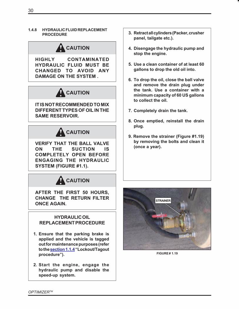
9. Remove the strainer (Figure #1.19)by removing the bolts and clean it(once a year).
3. Retract all cylinders (Packer, crusherpanel, tailgate etc.).
4. Disengage the hydraulic pump andstop the engine.
STRAINER
FIGURE # 1.19
31
MAINTENANCE
10. Clean inside the hydraulic tankwith a clean and dry cloth in order toremove any metal particles or debrisaccumulated at the bottom.
• To clean the interior of the analuminum tank (cylindrical), insertthe hand in the hole where thestrainer was fixed. This allows toclean one half of the tank. To cleanthe other half, remove the entirefilter at the rear side of the tank,insert the hand inside, and cleanwith the cloth.
• To clean the steel tank (Figure#|1.16), remove the access panel byremoving the retaining screw. Insertthe hand inside and clean the interiorwith the dry and clean cloth.
11. Change the return filter element(twice a year).
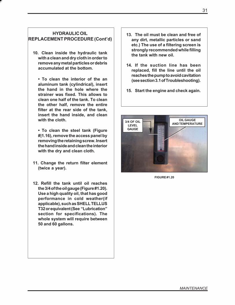
12. Refill the tank until oil reachesthe 3/4 of the oil gauge (Figure #1.20).Use a high quality oil, that has goodperformance in cold weather(ifapplicable), such as SHELL TELLUST32 or equivalent (See “Lubrication”section for specifications). Thewhole system will require between50 and 60 gallons.
13. The oil must be clean and free ofany dirt, metallic particles or sandetc.) The use of a filtering screen isstrongly recommended while fillingthe tank with new oil.
14. If the suction line has beenreplaced, fill the line until the oilreaches the pump to avoid cavitation(see section 3.1 of Troubleshooting).
15. Start the engine and check again.
OIL GAUGEAND TEMPERATURE3/4 OF OIL
LEVELGAUGE
FIGURE #1.20
HYDRAULIC OILREPLACEMENT PROCEDURE (Cont’d)
OPTIMIZERTM
32
HYDRAULIC FILTER REPLACEMENTPROCEDURE
• Shut off the hydraulic system andtruck engine;
• Shut off the ball valve on the suctionline (Figure #1.1).
• Remove the filter head’s fourretaining bolts (Shroeder type) orfront cap (Pall type) (Figure #1.16).
• Replace the filter element with anew one, compatible with themanufacturer's recommendations.Refer to hydraulic parts section.
• When replacing an in-tank filter beready to recuperate 2 gallons of oilapproximately. An in-tank returnfilter system has a self-closing valvepreventing the whole tank to emptyitself through the return filter core.
1.4.10 HYDRAULIC STRAINER CLEANINGPROCEDURE
HYDRAULIC STRAINERREPLACEMENT PROCEDURE
• Shut the engine off and let thehydraulic oil to cool down.
• Clean around the filler cap andremove it.
• Use a clean container of at least 60gallons to drop the old oil into.
• Once the tank is empty, replug thedrain valve. Shut the drain valve offand remove suction hose from ballvalve.
• Remove the strainer from tank port.
• Clean the strainer and perform avisual inspection for any damage.Replace at once if necessary. ADAMMAGED STRAINER COULDRESULT OF EXTENSIVE DAMAGETO THE PUMP.
• Refer to hydraulic fluid replacementprocedure for filling the tank backup.
1.4.9 HYDRAULIC FILTER REPLACEMENTPROCEDURE
To protect the components , the return filtermust be changed after the first 50 hours of use.Then the return filter must be changed once ayear. For part numbers refer to the hydraulicparts table. For replacement proceed asfollow:

33
MAINTENANCE
CAUTION
1.4.11 TAILGATE HYDRAULIC SYSTEMMAINTENANCE
The OPTIMIZERTM units are equipped with aspecial hydraulic system that controls thelocking mechanism of the tailgate.
If the continuous re-locking system is not workingproperly: tailgate unlocks by itself or if thetailgate is dropping from the fully open positionby itself refer to section 6.4 for troubleshooting.
1.4.12 CYCLE TIME TABLE FOR ALLHYDRAULIC FUNCTIONS
FUNCTIONS CYCLE TIME
Packer blade: 22 secTailgate: 45 secSliding roof: 15 secLifting arm: 15 secForks: 5 sec
Packer ejection mode:Extend 24 secRetract 10 sec
ENGINE RPM : 1500
1.4.12 BODY HOISTING SYSTEMMAINTENANCE
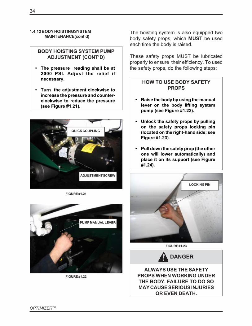
The OPTIMIZERTM is equipped with a hoistingsystem used to raised the body. This systemis fed by its own hydraulic pump (see Figure#1.21.
Since this pump is energized by electricalcables, it is protected by a cover.
The pump of the body hoisting system mustbe adjusted to 2000 PSI.
To do so, proceed with the following steps:
• Install a 3000PSI pressure gauge onthe quick coupling found on thepump (see Figure #1.21).
• By using the pump manual lever(see Figure #1.22), raise the bodyuntil the mechanism reaches theend of its stroke.
• Check the pressure while the bodyis held fully raised.
BODY HOISTING SYSTEM PUMPADJUSTMENT
ALWAYS BE EXTREMELYCAREFUL WHEN WORKING
NEAR THE PUMP ELECTRICALTERMINALS. FAILURE TO DO SO
MAY RESULT IN SERIOUSINJURIES, ELECTROCUTION OR
EVEN DEATH.
OPTIMIZERTM
34
1.4.12 BODY HOISTINGSYSTEMMAINTENANCE(cont’d)
BODY HOISTING SYSTEM PUMPADJUSTMENT (CONT’D)
• The pressure reading shall be at2000 PSI. Adjust the relief ifnecessary.
• Turn the adjustment clockwise toincrease the pressure and counter-clockwise to reduce the pressure(see Figure #1.21).
FIGURE #1.21
ADJUSTMENT SCREW
QUICK COUPLING
PUMP MANUAL LEVER
FIGURE #1.22
The hoisting system is also equipped twobody safety props, which MUST be usedeach time the body is raised.
These safety props MUST be lubricatedproperly to ensure their efficiency. To usedthe safety props, do the following steps:
HOW TO USE BODY SAFETYPROPS
• Raise the body by using the manuallever on the body lifting systempump (see Figure #1.22).
• Unlock the safety props by pullingon the safety props locking pin(located on the right-hand side; seeFigure #1.23).
• Pull down the safety prop (the otherone will lower automatically) andplace it on its support (see Figure#1.24).
LOCKING PIN
FIGURE #1.23
DANGER
ALWAYS USE THE SAFETYPROPS WHEN WORKING UNDERTHE BODY. FAILURE TO DO SOMAY CAUSE SERIOUS INJURIES
OR EVEN DEATH.

35
MAINTENANCE
1.4.12 BODY HOISTING SYSTEMMAINTENANCE(cont’d)
FIGURE #1.24
SAFETY PROPSUPPORT
SAFETY PROPS
To lubricate the body safety props, apply therecommended grease through the greasingpoints, which are located near the safetyprops shaft, inside the rails (see Figure#1.25). There are a greasing point on eachside.
FIGURE #1.25
The hoisting system also needs to belubricated properly. The greasing points arelocated on each hoisting system cylinder.One is located at the bottom of the cylindersand the other one is located at the top of thecylinders (see Figures #1.26 and 1.27).
SAFETY PROPGREASING POINT
FIGURE #1.24
BOTTOM GREASINGPOINT
FIGURE #1.25
TOP GREASING POINT
FIGURE #1.26
TOP OF CYLINDER
BOTTOM OF CYLINDER
OPTIMIZERTM
36
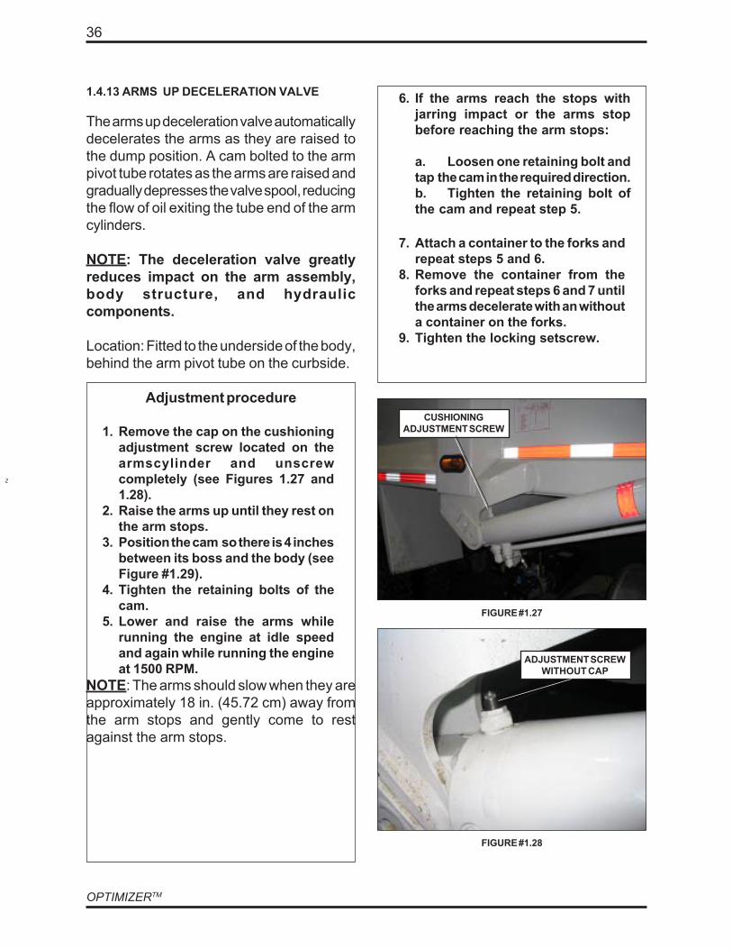
1.4.13 ARMS UP DECELERATION VALVE
The arms up deceleration valve automaticallydecelerates the arms as they are raised tothe dump position. A cam bolted to the armpivot tube rotates as the arms are raised andgradually depresses the valve spool, reducingthe flow of oil exiting the tube end of the armcylinders.
NOTE: The deceleration valve greatlyreduces impact on the arm assembly,body structure, and hydrauliccomponents.
Location: Fitted to the underside of the body,behind the arm pivot tube on the curbside.
Adjustment procedure
1. Remove the cap on the cushioningadjustment screw located on thearmscylinder and unscrewcompletely (see Figures 1.27 and1.28).
2. Raise the arms up until they rest onthe arm stops.
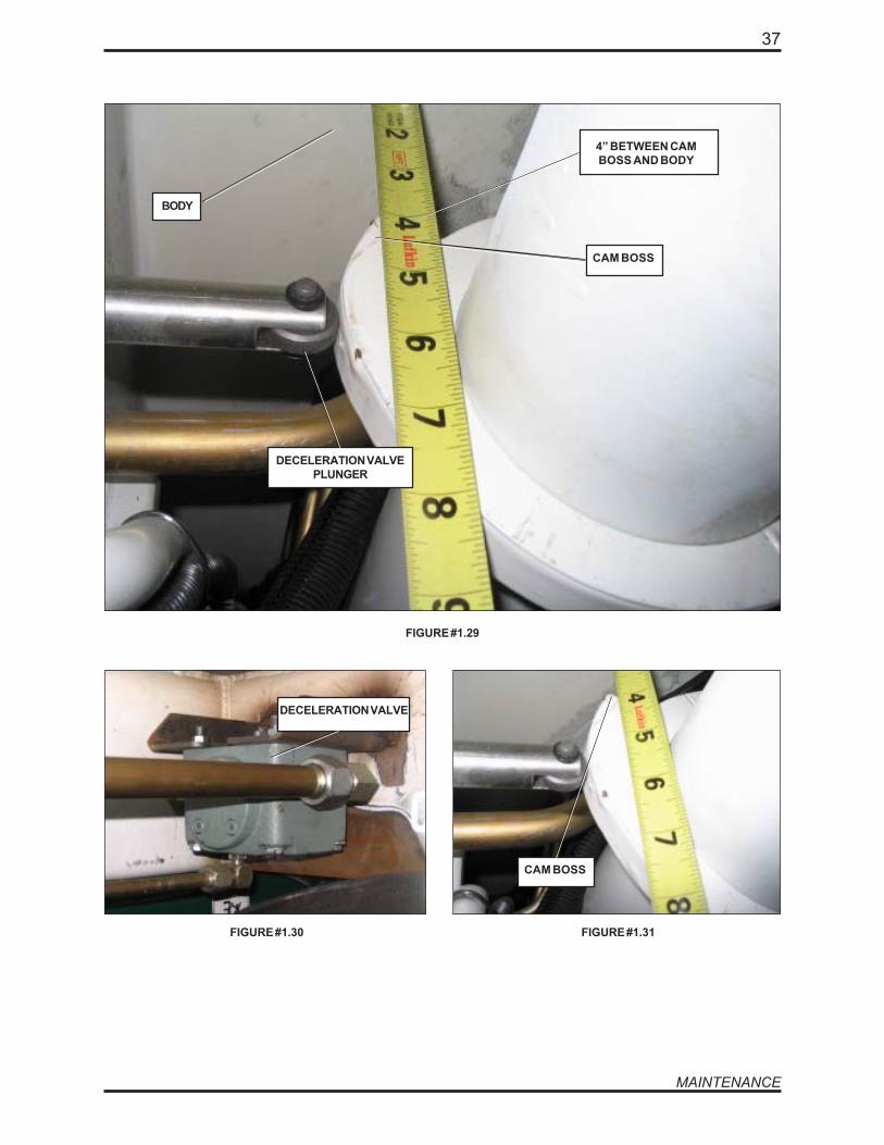
3. Position the cam so there is 4 inchesbetween its boss and the body (seeFigure #1.29).
4. Tighten the retaining bolts of thecam.
5. Lower and raise the arms whilerunning the engine at idle speedand again while running the engineat 1500 RPM.
NOTE: The arms should slow when they areapproximately 18 in. (45.72 cm) away fromthe arm stops and gently come to restagainst the arm stops.
7. Attach a container to the forks andrepeat steps 5 and 6.
8. Remove the container from theforks and repeat steps 6 and 7 untilthe arms decelerate with an withouta container on the forks.
9. Tighten the locking setscrew.
ADJUSTMENT SCREWWITHOUT CAP
FIGURE #1.27
CUSHIONINGADJUSTMENT SCREW
6. If the arms reach the stops withjarring impact or the arms stopbefore reaching the arm stops:
a. Loosen one retaining bolt andtap the cam in the required direction.b. Tighten the retaining bolt ofthe cam and repeat step 5.
FIGURE #1.28
37
MAINTENANCE
FIGURE #1.29
CAM BOSS
BODY
4” BETWEEN CAMBOSS AND BODY
DECELERATION VALVEPLUNGER
DECELERATION VALVE
FIGURE #1.30 FIGURE #1.31
CAM BOSS
OPTIMIZERTM
38
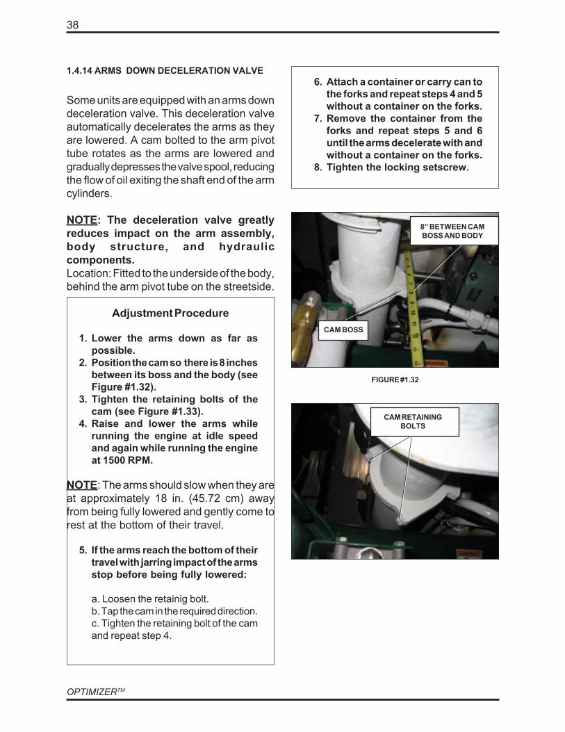
1.4.14 ARMS DOWN DECELERATION VALVE
Some units are equipped with an arms downdeceleration valve. This deceleration valveautomatically decelerates the arms as theyare lowered. A cam bolted to the arm pivottube rotates as the arms are lowered andgradually depresses the valve spool, reducingthe flow of oil exiting the shaft end of the armcylinders.
NOTE: The deceleration valve greatlyreduces impact on the arm assembly,body structure, and hydrauliccomponents.Location: Fitted to the underside of the body,behind the arm pivot tube on the streetside.
Adjustment Procedure
1. Lower the arms down as far aspossible.
2. Position the cam so there is 8 inchesbetween its boss and the body (seeFigure #1.32).
3. Tighten the retaining bolts of thecam (see Figure #1.33).
4. Raise and lower the arms whilerunning the engine at idle speedand again while running the engineat 1500 RPM.
NOTE: The arms should slow when they areat approximately 18 in. (45.72 cm) awayfrom being fully lowered and gently come torest at the bottom of their travel.
5. If the arms reach the bottom of theirtravel with jarring impact of the armsstop before being fully lowered:
a. Loosen the retainig bolt.b. Tap the cam in the required direction.c. Tighten the retaining bolt of the camand repeat step 4.
6. Attach a container or carry can tothe forks and repeat steps 4 and 5without a container on the forks.
7. Remove the container from theforks and repeat steps 5 and 6until the arms decelerate with andwithout a container on the forks.
8. Tighten the locking setscrew.
FIGURE #1.32
CAM BOSS
8” BETWEEN CAMBOSS AND BODY
CAM RETAININGBOLTS

39
MAINTENANCE
1.5 AIR SYSTEM MAINTENANCE
1.5.1 AIR SYSTEM MAINTENANCEPROCEDURE
Air system is crucial for the brakes to operatewith maximum efficiency. All air tanks on thechassis must be drained after each workingday.Some units are equipped with an air dryerand/or alcohol evaporator. These devicesare used to reduce water in the air system,preventing air components to corrode or tofreeze in cold weather.
To perform maintenance on the air dryer andalcohol evaporator, refer to the chassismanufacturer maintenance manual.
To avoid loss of air control on packer blade(especially under cold/wet weatherconditions), we strongly recommend to checkthe following items:
AIR SYSTEM MAINTENANCEPROCEDURE
• Ensure that the parking brake isapplied and the vehicle is taggedout for maintenance purposes (referto the section 1.1.4 “Lockout/Tagoutprocedure”).
• Drain all the air tanks daily.
• Change absorbant material in theair dryer twice a year: On this typeof equipment the compressor worksall the time (Frequent use of breaksystem). As a consequence, a lot ofmoisture is injected into the airsystem. See chassis manufacturerrecommandations.
• Twice a year, lubricate the airactuator and solenoid valve foundon the main valve with light (lowtemperature) oil.
OPTIMIZERTM
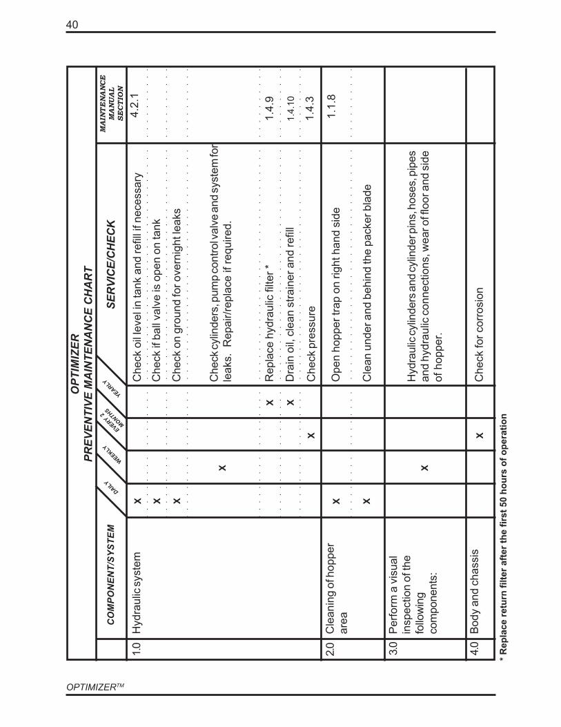
40
2.0 4.0
* Rep
lace
retu
rn fi
lter a
fter t
he fi
rst 5
0 ho
urs
of o
pera
tion
Cle
anin
g of
hop
per
area
3.0
Per
form
a v
isua
lin
spec
tion
of th
efo
llow
ing
com
pone
nts:
Bod
y an
d ch
assi
s
1.0
Hyd
raul
ic sy
stem
CO
MPO
NEN
T/SY
STEM
OPT
IMIZ
ERPR
EVEN
TIVE
MA
INTE
NA
NC
E C
HA
RT
MAINTENANCE
MANUAL
SECTION
SER
VIC
E/C
HEC
KYEARLY
WEEKLY
X
Che
ck if
bal
l val
ve is
ope
n on
tank
Che
ck o
il le
vel i
n ta
nk a
nd re
fill i
f nec
essa
ry
Che
ck o
n gr
ound
for o
vern
ight
leak
s
Che
ck cy
linde
rs, p
ump
cont
rol v
alve
and
syst
em fo
rle
aks.
Rep
air/r
epla
ce if
requ
ired.
Rep
lace
hyd
raul
ic fi
lter *
Dra
in o
il, c
lean
stra
iner
and
refil
l
Che
ck p
ress
ure
Ope
n ho
pper
trap
on
right
han
d si
de
1.4.
3
1.4.
10
1.4.
9
1.1.
8
Hyd
raul
ic cy
linde
rs a
nd cy
linde
r pin
s, h
oses
, pip
esan
d hy
drau
lic c
onne
ctio
ns, w
ear o
f flo
or a
nd s
ide
of h
oppe
r.
Che
ck fo
r cor
rosi
on
EVERY 2
MONTHSDAILY
Cle
an u
nder
and
beh
ind
the
pack
er b
lade
4.2.
1
X X
X
X X
X
X X
X
X

41
MAINTENANCE
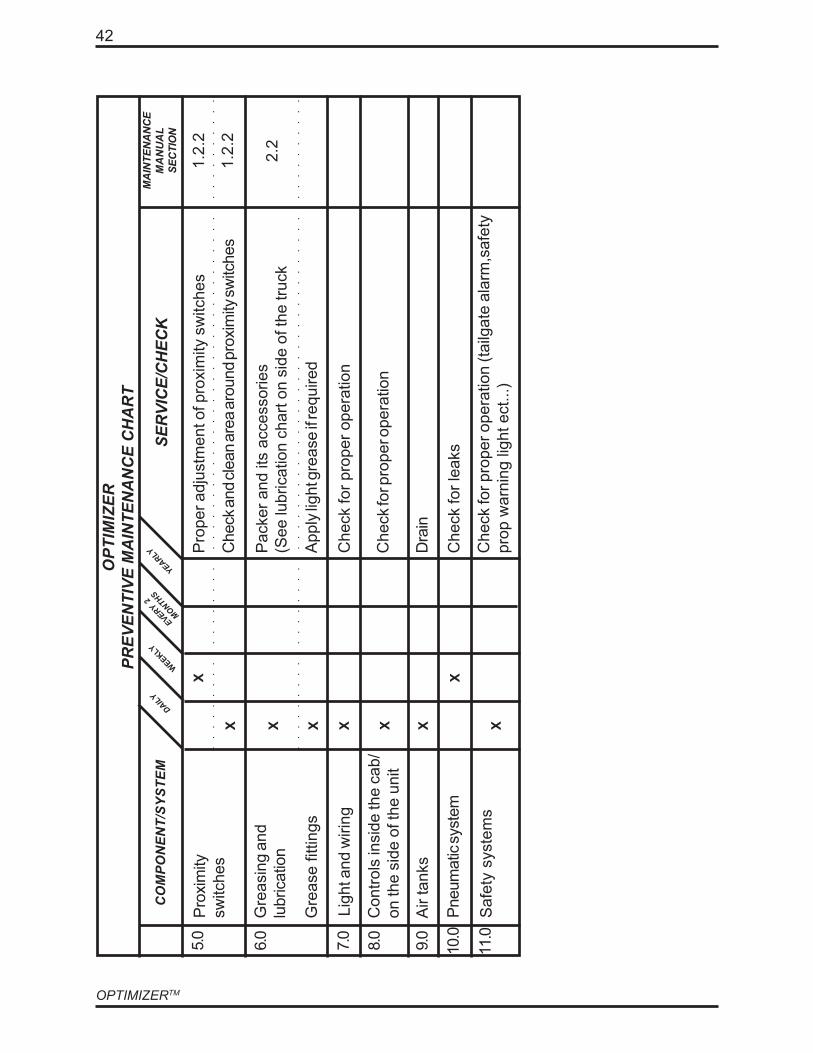
OPTIMIZERTM
42
1.2.
2
1.2.
2Pr
oxim
itysw
itche
s
Gre
asin
g an
dlu
bric
atio
n2.
2
Saf
ety
syst
ems
Pro
per a
djus
tmen
t of p
roxi
mity
sw
itche
s
Che
ck an
d cle
an ar
ea ar
ound
prox
imity
switc
hes
Pac
ker a
nd it
s ac
cess
orie
s(S
ee lu
bric
atio
n ch
art o
n si
de o
f the
truc
k
Appl
y lig
ht g
reas
e if r
equi
red
Che
ck fo
r pro
per o
pera
tion
Che
ck fo
r pro
per o
pera
tion
Dra
in
Che
ck fo
r lea
ks
Che
ck fo
r pro
per o
pera
tion
(tailg
ate
alar
m,s
afet
ypr
op w
arni
ng li
ght e
ct...
)
Air
tank
s
Pneu
mat
ic sy
stem
Ligh
t and
wiri
ng
Con
trols
insi
de th
e ca
b/on
the
side
of t
he u
nit
6.0
11.0
10.0
5.0
CO
MPO
NEN
T/SY
STEM
OPT
IMIZ
ERPR
EVEN
TIVE
MA
INTE
NA
NC
E C
HA
RT
MA
INTE
NA
NC
EM
AN
UA
LSE
CTI
ON
SER
VIC
E/C
HEC
KYEARLY
WEEKLY
X
EVERY 2
MONTHSDAILY
7.0
8.0
9.0
X X XG
reas
e fit
tings
X X X
X
X

43
LUBRICATION
OPTIMIZERTM
44
2.0 LUBRICATION.................................................................................................... 462.1 RECOMMENDED LUBRICANT ........................................................................... 46
2.1.1 HYDRAULIC FLUIDS ......................................................................................... 462.1.2 MOTOR OIL FOR VEHICLE ................................................................................ 462.1.3 GREASE ............................................................................................................ 46
LABRIE OPTIMIZER
CHAPTER 2.0
Table of contents

45
LUBRICATION
OPTIMIZERTM
46
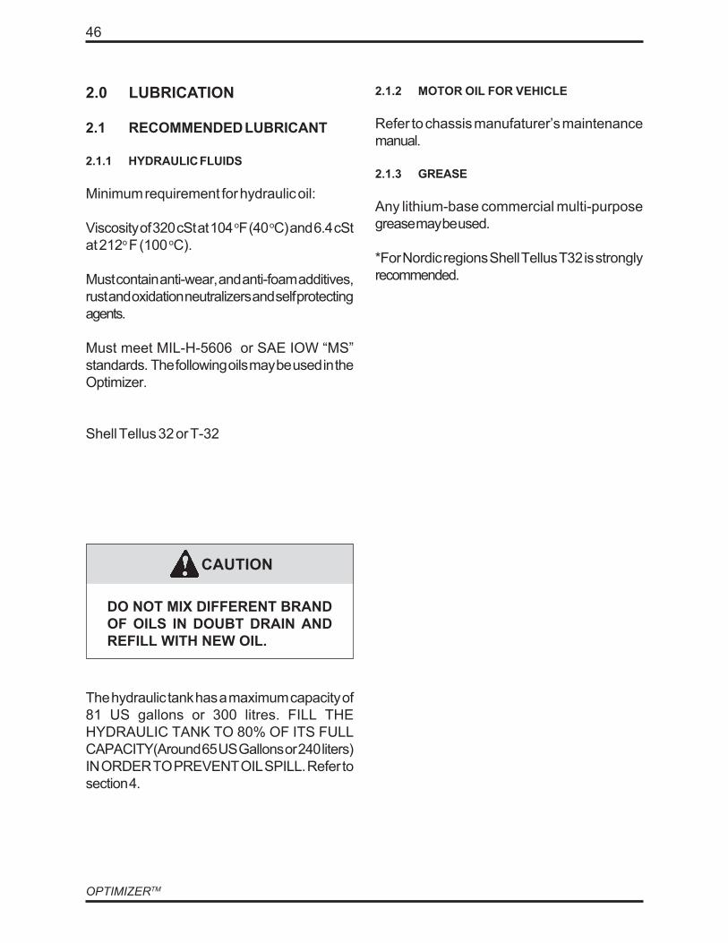
2.0 LUBRICATION
2.1 RECOMMENDED LUBRICANT
2.1.1 HYDRAULIC FLUIDS
Minimum requirement for hydraulic oil:
Viscosity of 320 cSt at 104 oF (40 oC) and 6.4 cStat 212o F (100 oC).
Must contain anti-wear, and anti-foam additives,rust and oxidation neutralizers and self protectingagents.
Must meet MIL-H-5606 or SAE IOW “MS”standards. The following oils may be used in theOptimizer.
Shell Tellus 32 or T-32
2.1.2 MOTOR OIL FOR VEHICLE
Refer to chassis manufaturer’s maintenancemanual.
2.1.3 GREASE
Any lithium-base commercial multi-purposegrease may be used.
*For Nordic regions Shell Tellus T32 is stronglyrecommended.
DO NOT MIX DIFFERENT BRANDOF OILS IN DOUBT DRAIN ANDREFILL WITH NEW OIL.
CAUTION
The hydraulic tank has a maximum capacity of81 US gallons or 300 litres. FILL THEHYDRAULIC TANK TO 80% OF ITS FULLCAPACITY(Around 65 US Gallons or 240 liters)IN ORDER TO PREVENT OIL SPILL. Refer tosection 4.

47
LUBRICATION

OPTIMIZERTM
48
LUBRICATION CHART ON SIDE OF THE TRUCK

49
TROUBLESHOOTING
OPTIMIZERTM
50
LABRIE OPTIMIZER
CHAPTER 3.0
Table of contents
3.0 TROUBLESHOOTING SECTION ...................................................................... 523.1 TROUBLESHOOTING TABLE ............................................................................. 523.2 INTERNAL LEAK DETECTION FOR CYLINDERS .............................................. 553.3 TAILGATE LOCKING MECHANISM TROUBLESHOOTING ................................ 563.4 MAIN HYDRAULIC SCHEMATIC.......................................................................... 60

51
TROUBLESHOOTING

OPTIMIZERTM
52
3.0 TROUBLESHOOTINGSECTION
3.1 TROUBLESHOOTING TABLEImportant: at all times when troubleshootingrefer to the corresponding sections.
Insufficient packing ratio 1. Low oil pressure 1. Check if oil pressure at reliefvalve is 2500 PSI or Faultyhydraulic pump (cavitation orwear).
2. See section 3.22. The packer hydraulic cylindersare internally by-passing
3. Wrong method of loading wasteor type of waste
3. See Operator Manual)
PROBLEMS POSSIBLE CAUSES REMEDY
5. Clean the suction strainer,replace the return filter andchange oil.
4. Add oil to required level
3. Hydraulic pressure is too high
4. Oil level in reservoir too low
5. Contaminated oil
3. Set the pressure at the relief valveto 2500 PSI
2. See section 2.0 for proper oilto use.
2. NOT THE PROPER GRADE OFOIL. ie. :Too thin in hottemperatures or too thick in coldtemperatures.
1. Faulty pump or faultyrelief valveHydraulic oil is over heating(morethan 77°C, + or - 4°C,180°Formore,+ or - 10°F.)
1. When the hydraulic oil is cooledoff, turn on hydraulic system andwork the packer for 2 or 3minutes.Then touch the pumpand relief valve. If they are faulty,they will be much hotter than theother components on thehydraulic system.
Oil foaming 1. Air getting into the system
3. Low oil level 3. Refill the reservoir
2. Empty oil and refill with anti-foam
1. Tighten the connections throughthe hose between the pump andthe reservoir
2. Not the proper grade of oilhydraulic oil

53
TROUBLESHOOTING
3.1 TROUBLESHOOTING TABLE (continued)
PROBLEMS POSSIBLE CAUSES REMEDY
5. Ball valve partly closed
4. Suction hose blocked
3. Dirty strainer
2. Oil too thick
1. Low oil level 1. Refill the reservoirCavitation, excessive noise fromthe pump
2. Change oil for an appropriategrade of oil according to theambiant temperature.
3. Clean and/or change the strainer.
4. Unblock the hose.
5. Open the valve completely
2. Check if the relief valve isworking properly.
3. After any repairs was thehydraulics properly cleaned?
2. Is the hydraulic oil clean?2. Invisible miniature particles.
1. Have the strainer, return filtercanister been changed asrequired?
1. Abrasive wear caused by smallparticles.
The diaphragm (wear end plate)and/or pump casing and/or gearteeth have grooves on them (Donot take apart a pump that is stillcovered by warranty).
2. Over pressure.Pump casing is cracked.
1. Check to see if the suction on thereservoir is opened.
1. Oil overheating more than 77 C(180o F).
Blue or black valve diaphragm.
OPTIMIZERTM
54
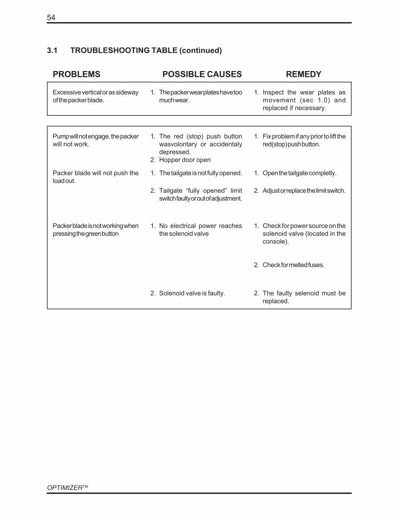
1. The packer wear plates have toomuch wear.
3.1 TROUBLESHOOTING TABLE (continued)
PROBLEMS POSSIBLE CAUSES REMEDY
Excessive vertical or as sidewayof the packer blade.
1. Inspect the wear plates asmovement (sec 1.0) andreplaced if necessary.
2. The faulty selenoid must bereplaced.
2. Check for melted fuses.
2. Solenoid valve is faulty.
1. No electrical power reachesthe solenoid valve
1. Check for power source on thesolenoid valve (located in theconsole).
2. Adjust or replace the limit switch.
1. Open the tailgate completly.1. The tailgate is not fully opened.
2. Tailgate “fully opened” limitswitch faulty or out of adjustment.
Packer blade is not working whenpressing the green button
Packer blade will not push theload out.
1. Fix problem if any prior to lift thered(stop) push button.
1. The red (stop) push buttonwasvolontary or accidentalydepressed.
2. Hopper door open
Pump will not engage, the packerwill not work.

55
TROUBLESHOOTING
INTERNAL LEAK DETECTIONFOR CYLINDERS
1. Apply all safety measures to ensuresafety around the vehicle at alltimes.
2. Ensure that the parking brake isapplied.
3. Pull out the Emergency Stop Button(red).
4. Start the engine and engage thehydraulic pump.
5. Fully extend the packer cylinders.6. Disengage the hydraulic pump.7. Disconnect the hose at end A.8. Plug the end of the disconnected
hose.9. Put pressure on the piston end.10. If oil leaks out of end A, there is an
internal leak. Replace damagedparts.
INTERNAL LEAK DETECTION FORCYLINDERS
3.2 INTERNAL LEAK DETECTIONFOR CYLINDERS
1.
2.
3.
4.
5.
6.
FIGURE #3.1
A
A
An internal leak is caused by a damaged sealinside the hydraulic cylinder. Because thecylinder is leaking oil inside (bypassing), acertain amount of pressure is lost reducingthe cylinder efficiency and its capacity topush or pull.
If the packer cylinders are bypassing, theseal inside the cylinder may require to bereplaced. If an internal leak is suspected,apply the following procedure to verify it:

OPTIMIZERTM
56
3.3 TAILGATE LOCKING MECHANISM TROUBLESHOOTING
The tailgate locking mechanism is equipped with hydraulic safety systems that preventaccidental unlocking of the tailgate during operation. One of the systems is the velocity fusewith the “power bleed” and the other is the holding valve.The spool inside the tailgate section of the valve is designed in such a way, that it will allowpressure to pass through it each time the pressure is building up in the hydraulic system (i.e.:when the packer is working). The pressure “burst” goes to the holding valve into port “D1”and then out to the cylinder by port “U1”. This will keep the tailgate cylinders pressurized andthe tailgate closed when packing material.The velocity fuse, located on the valve (Figure #3.3), will make sure to drain any slow movingoil coming from the piston side of the tailgate cylinders. Since the rod side is being pressurizedwith the “Power bleed” system, the other side has to drain to avoid any pressure build-up.The velocity fuse makes the piston side open to tank when the oil is moving under 3 gallonsper minute and will shut when a flow signal is sent.NOTE: Refer to the main hydraulic schematic.
Holding valve Tailgate
PortU2
Port U1
Port D1
Port D2
FIGURE #3.2

57
TROUBLESHOOTING
Main relief
Gauge port
Velocityfuse
FIGURE #3.3
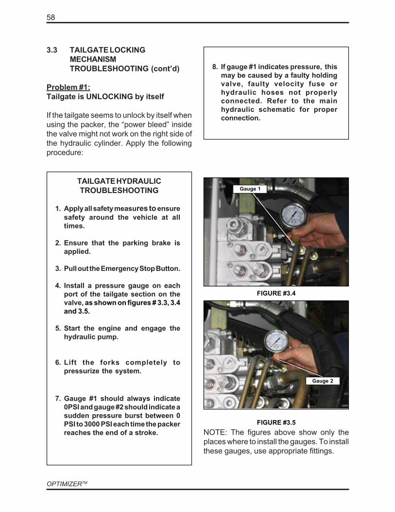
Gauge 1
Gauge 2
OPTIMIZERTM
58
TAILGATE HYDRAULICTROUBLESHOOTING
1. Apply all safety measures to ensuresafety around the vehicle at alltimes.
2. Ensure that the parking brake isapplied.
3. Pull out the Emergency Stop Button.
4. Install a pressure gauge on eachport of the tailgate section on thevalve, as shown on figures # 3.3, 3.4and 3.5.
5. Start the engine and engage thehydraulic pump.
6. Lift the forks completely topressurize the system.
3.3 TAILGATE LOCKINGMECHANISMTROUBLESHOOTING (cont’d)
Problem #1:Tailgate is UNLOCKING by itself
If the tailgate seems to unlock by itself whenusing the packer, the “power bleed” insidethe valve might not work on the right side ofthe hydraulic cylinder. Apply the followingprocedure:
FIGURE #3.4
Gauge 1
FIGURE #3.5
8. If gauge #1 indicates pressure, thismay be caused by a faulty holdingvalve, faulty velocity fuse orhydraulic hoses not properlyconnected. Refer to the mainhydraulic schematic for properconnection.
Gauge 2
NOTE: The figures above show only theplaces where to install the gauges. To installthese gauges, use appropriate fittings.
7. Gauge #1 should always indicate0PSI and gauge #2 should indicate asudden pressure burst between 0PSI to 3000 PSI each time the packerreaches the end of a stroke.
59
TROUBLESHOOTING
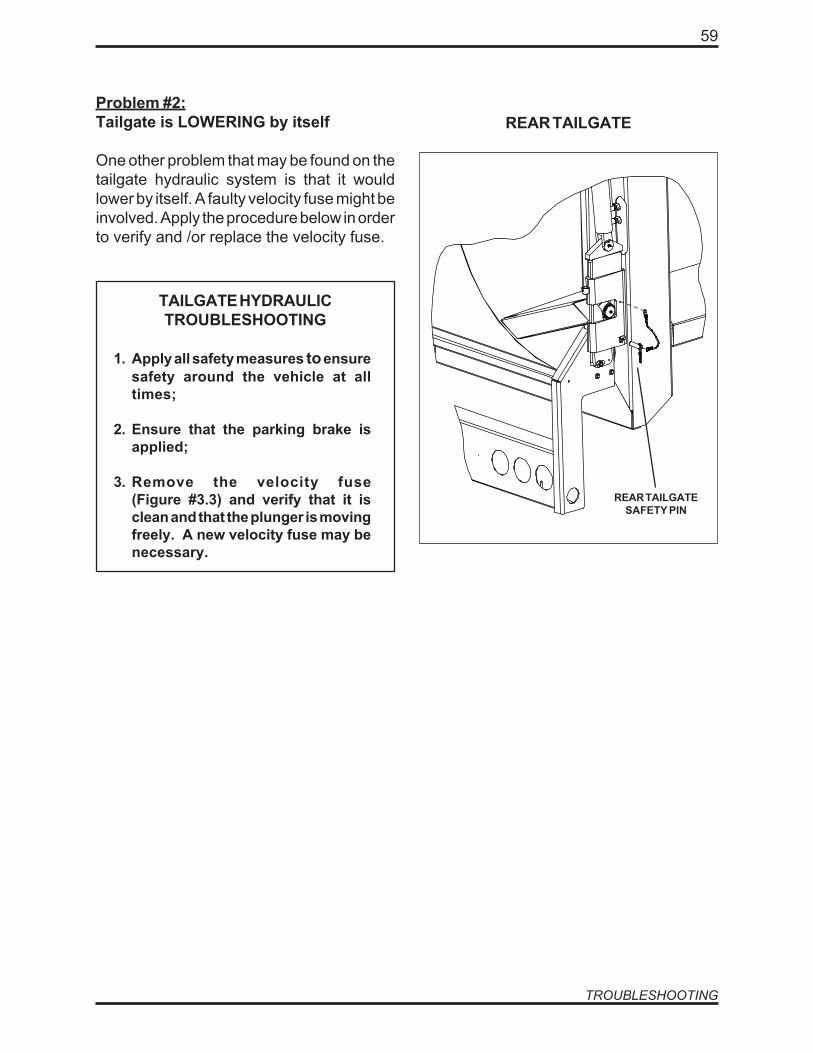
TAILGATE HYDRAULICTROUBLESHOOTING
1. Apply all safety measures to ensuresafety around the vehicle at alltimes;
2. Ensure that the parking brake isapplied;
3. Remove the velocity fuse(Figure #3.3) and verify that it isclean and that the plunger is movingfreely. A new velocity fuse may benecessary.
Problem #2:Tailgate is LOWERING by itself
One other problem that may be found on thetailgate hydraulic system is that it wouldlower by itself. A faulty velocity fuse might beinvolved. Apply the procedure below in orderto verify and /or replace the velocity fuse.
REAR TAILGATE
REAR TAILGATESAFETY PIN

OPTIMIZERTM
60
3.4 MAIN HYDRAULIC SCHEMATIC

61
TROUBLESHOOTING
Intentionally left blank

OP
TIMIZE
RTM
62
LAB
RIE O
PTIMIZER
CH
APTER
4.0
Table of contents
4.0H
YDR
AU
LIC SYSTEM
S PAR
TS AN
D D
IAG
RA
MS
............................................644.1
HYD
RAU
LIC H
OSES AN
D PIPES O
N C
HASSIS
.................................................644.1.1
HO
W TO
OR
DER
...............................................................................................644.1.2
HYD
RAU
LIC PIPIN
G TAN
K TO PU
MP (PETER
BILT A320 4*2)..........................654.2
PUM
PS, VALVES AND
HYD
RAU
LIC TAN
K..........................................................67
4.2.1H
YDR
AULIC
TANK
.............................................................................................674.2.2
MU
NC
IE HYD
RAU
LIC PU
MP
.............................................................................694.2.3
MAIN
VALVE
......................................................................................................71

63
HYDRAULIC
OP
TIMIZE
RTM
644.0H
YDR
AU
LIC SYSTEM
S PAR
TS AN
D D
IAG
RA
MS
4.1H
YDR
AU
LIC H
OSES A
ND
PIPES ON
CH
ASSIS
4.1.1H
OW
TO O
RD
ER
When ordering hydraulic com
ponents, always specify the follow
ing:
a)Body serial num
ber: eg. FL98HH
A
b)Type of body• 40 cubic yards
This capacity determines the length of the body therefore the type of hydraulic pipes, hoses, hoists
and pumps.
c)Type of pum
p• M
uncie Live Pack
• Denison V
ane Pum
p
d)Type of chassis w
ith wheel configuration, eg. P
eterbilt A320 6x4
e) Type of transm
ission, eg. Allison MD
3560

65
HYDRAULIC
4.1.2 HYDRAULIC PIPING TANK TO PUMP(PETERBILT A320 4*2)

OPTIMIZERTM
66
4.1.2 HYDRAULIC PIPING TANK TO PUMP (PETERBILTA320 4*2)
NO. PART NO. DESCRIPTION QTY.
1 5008 RAIL, TUBE HOLDER 8” ................................................................................................... 12 16949 TANK RETURN HOSE ....................................................................................................... 13 21742 PUMP RETURN HOSE ...................................................................................................... 14 36079 DRAIN VALVE HOSE ........................................................................................................ 15 37494 PUMP SUCTION HOSE ..................................................................................................... 16 41774 SUCTION TUBING ............................................................................................................. 17 41798 SUPPORT, HYDRAULIC TUBING ASSY ........................................................................... 18 60662 BODY RETURN HOSE ...................................................................................................... 19 60685 SUPPORT, HYDRAULIC TUBING ASSY ........................................................................... 110 73335 TANK SUCTION HOSE ...................................................................................................... 111 76842 PACKER RETURN HOSE .................................................................................................. 112 76857 SUPPORT ......................................................................................................................... 113 76859 HYDRAULIC HOSE ........................................................................................................... 114 76880 HYDRAULIC HOSE ........................................................................................................... 115 76923 HYDRAULIC HOSE, PUMP PRESSURE ........................................................................... 116 76926 HYDRAULIC HOSE, BODY PRESSURE ........................................................................... 117 76928 SUPPORT ......................................................................................................................... 118 77403 SUPPORT ......................................................................................................................... 119 HYC00120 2.5” CLAMP ...................................................................................................................... 420 HYF06280 T FITTING .......................................................................................................................... 121 HYS00450 1.25” CLAMP .................................................................................................................... 622 HYS00460 0.5” HOSE SUPPORT ....................................................................................................... 123 HYS00550 2.25” HOSE SUPPORT ..................................................................................................... 424 HYS00560 2.5” HOSE SUPPORT ....................................................................................................... 3

67
HYDRAULIC
4.2 PUMPS, VALVES AND HYDRAULIC TANK4.2.1 HYDRAULIC TANK
OPTIMIZERTM
68
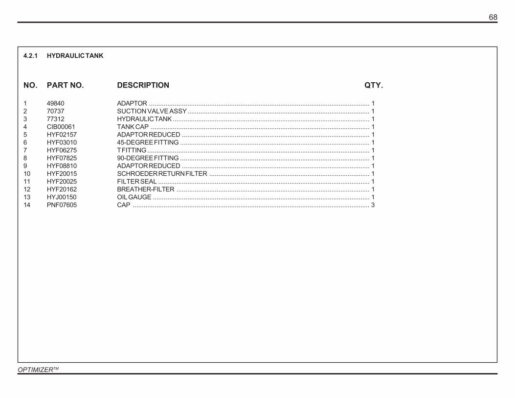
NO. PART NO. DESCRIPTION QTY.
1 49840 ADAPTOR ......................................................................................................................... 12 70737 SUCTION VALVE ASSY.................................................................................................... 13 77312 HYDRAULIC TANK ............................................................................................................ 14 CIB00061 TANK CAP ........................................................................................................................ 15 HYF02157 ADAPTOR REDUCED ....................................................................................................... 16 HYF03010 45-DEGREE FITTING ........................................................................................................ 17 HYF06275 T FITTING .......................................................................................................................... 18 HYF07825 90-DEGREE FITTING ........................................................................................................ 19 HYF08810 ADAPTOR REDUCED ....................................................................................................... 110 HYF20015 SCHROEDER RETURN FILTER ........................................................................................ 111 HYF20025 FILTER SEAL .................................................................................................................... 112 HYF20162 BREATHER-FILTER .......................................................................................................... 113 HYJ00150 OIL GAUGE ....................................................................................................................... 114 PNF07605 CAP .................................................................................................................................. 3
4.2.1 HYDRAULIC TANK
69
HYDRAULIC
12
11
10
9
8
7
6
5
5
4
4
3
2
1
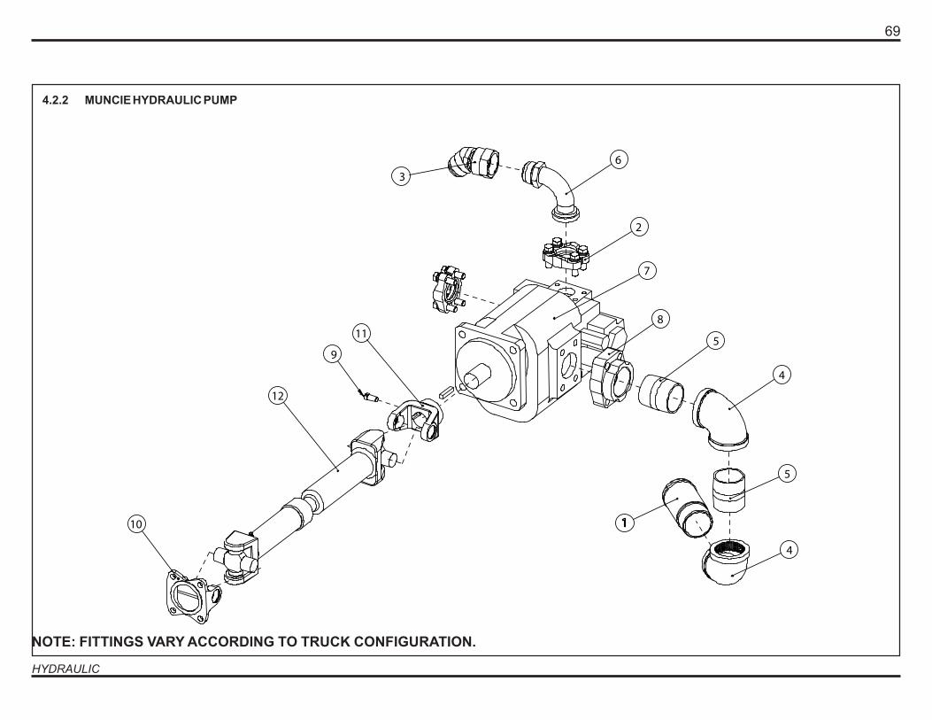
4.2.2 MUNCIE HYDRAULIC PUMP
NOTE: FITTINGS VARY ACCORDING TO TRUCK CONFIGURATION.

OPTIMIZERTM
70
NO. PART NO. DESCRIPTION QTY.
1 12635 SPECIAL FITTING............................................................................................................. 12 HYF00095 SPLIT FLANGE HARDWARE) ........................................................................................... 23 HYF07870 HYDRAULIC FITTING ........................................................................................................ 14 HYF13100 90-DEGREE FITTING ....................................................................................................... 25 HYF13800 FITTING ............................................................................................................................. 26 HYF25015 ADAPTOR ......................................................................................................................... 17 HYP01175 MUNCIE LIVE PACK PUMP ............................................................................................. 18 HYS02500 TYRONE ADAPTOR .......................................................................................................... 19 QUB00700 BOLT ................................................................................................................................. 110 QUY00200 YOKE WITH FLANGE ....................................................................................................... 111 QUY00400 YOKE FOR PUMP ............................................................................................................. 112 SUD00412 DRIVING SHAFT ............................................................................................................... 1
4.2.2 MUNCIE HYDRAULIC PUMP
71
HYDRAULIC
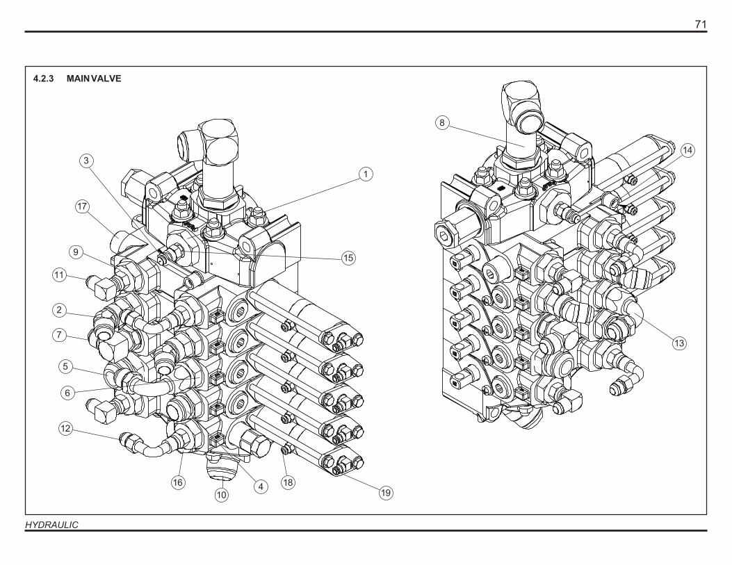
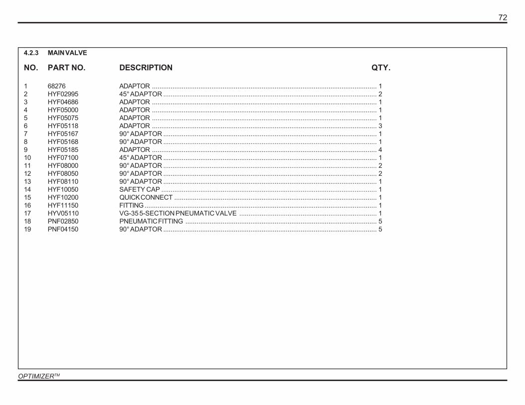
4.2.3 MAIN VALVE
17
16
1
10
15
3
2
11
9
7
5
6
12
4 1819
8
14
13
OPTIMIZERTM
72
NO. PART NO. DESCRIPTION QTY.
1 68276 ADAPTOR ......................................................................................................................... 12 HYF02995 45° ADAPTOR ................................................................................................................... 23 HYF04686 ADAPTOR ......................................................................................................................... 14 HYF05000 ADAPTOR ......................................................................................................................... 15 HYF05075 ADAPTOR ......................................................................................................................... 16 HYF05118 ADAPTOR ......................................................................................................................... 37 HYF05167 90° ADAPTOR ................................................................................................................... 18 HYF05168 90° ADAPTOR ................................................................................................................... 19 HYF05185 ADAPTOR ......................................................................................................................... 410 HYF07100 45° ADAPTOR ................................................................................................................... 111 HYF08000 90° ADAPTOR ................................................................................................................... 212 HYF08050 90° ADAPTOR ................................................................................................................... 213 HYF08110 90° ADAPTOR ................................................................................................................... 114 HYF10050 SAFETY CAP .................................................................................................................... 115 HYF10200 QUICK CONNECT ............................................................................................................. 116 HYF11150 FITTING ............................................................................................................................. 117 HYV05110 VG-35 5-SECTION PNEUMATIC VALVE .......................................................................... 118 PNF02850 PNEUMATIC FITTING ....................................................................................................... 519 PNF04150 90° ADAPTOR ................................................................................................................... 5
4.2.3 MAIN VALVE

73
HYDRAULIC
Intentionally Left Blank
74 BO
DY
AIR
SY
STE
MS LA
BR
IE OPTIM
IZER
CH
APTER
5.0
Table of contents
5.0B
OD
Y AIR
SYSTEMS, PA
RTS A
ND
DIA
GR
AM
S...............................................75
5.1IN
TRO
DU
CTIO
N.................................................................................................75
5.2G
ENER
EAL PNEU
MATIC
DIAG
RAM
...................................................................77

BO
DY
AIR
SY
STE
MS 75
5.0B
OD
Y AIR
SYSTEMS, PA
RTS A
ND
DIA
GR
AM
S
5.1IN
TRO
DU
CTIO
N
This section contains a diagram presenting the pneum
atic system of an O
ptimizer TM body.

76 BO
DY
AIR
SY
STE
MS

77
BODY AIR SYSTEMS
5.2 GENERAL PNEUMATIC DIAGRAM

OPTIMIZERTM
78
Intentionally Left Blank
ELE
CTR
ICA
L
LAB
RIE O
PTIMIZER
CH
APTER
6.0
Table of contents
6.0ELEC
TRIC
AL SYSTEM
S...................................................................................80
6.1ELEC
TRIC
AL SCH
EMATIC
S...............................................................................80
6.2D
ELASTEK MO
DU
LE..........................................................................................80
806.0ELEC
TRIC
AL SYSTEM
S
6.1ELEC
TRIC
AL SC
HEM
ATIC
S A
ll the electrical schematics needed to troubleshoot and repair your
Optim
izer TM unit are provided with the truck. They are located inside the cab.
For further assistance, call Labrie Environm
ental Group C
ustomer S
upport Center
at 1-800-231-2771.
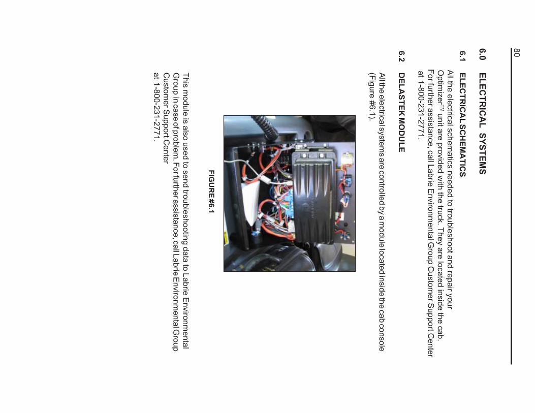
6.2D
ELASTEK
MO
DU
LE
All the electrical systems are controlled by a m
odule located inside the cab console(Figure #6.1).
FIGU
RE #6.1
This module is also used to send troubleshooting data to Labrie E
nvironmental
Group
in case of problem. For further assistance, call Labrie Environm
ental Group
Custom
er Support C
enterat 1-800-231-2771.

81
NO
TES


