56
LabVIEW Driver Supplement to the Spectrometer Control Manual Part Number 80123A

LabVIEW Driver Supplement to the
Spectrometer Control Manual Part Number 80123A

2
Copyright © July, 11 Instruments S.A., Inc., JOBIN YVON-SPEX Division. All rights Reserved. Portions of the software described in this document Copyright © Microsoft Corporation and National Instruments Corporation. All rights Reserved. No part of this document may be reproduced, stored in a retrieval system, or transmitted in any form by any means, including electronic or mechanical, photocopying and recording without prior written permission of Instruments S.A., Inc., JOBIN YVON-SPEX Division. Requests for permission should be submitted in writing. Information in this document is subject to change without notice and does not represent a commitment on the part of the vendor.
3
About the Manuals You may have more than one manual, depending on your system configuration. To find the manual that has the information you need, these guidelines may help.
• Each manual generally covers a product and the features and accessories peculiar to and/or contained within that product.
• Accessories that can be applied to other products are normally covered by separate documentation. • Software that is exclusively used with one instrument or system is covered in the manual for that product. • Software that can be used with a number of other products is covered in its own manual. • If you are reading about a product that interacts with other products, you will be referred to other
documentation as necessary. This manual covers both the LabVIEW spectrometer drivers and CCD drivers. These products are provided separately therefore you may not have both sets.

4

5
Table of Contents: ABOUT THE MANUALS ..........................................................................................................................................3
TABLE OF CONTENTS: ...........................................................................................................................................5
OVERVIEW OF LABVIEW DRIVERS ...................................................................................................................7
LABVIEW DRIVER FOR HJY (ISA) SPECTROMETER CONTROLLE RS .....................................................8
Hardware Requirements: ...........................................................................................................................................8 Installing the ISA Libraries:.......................................................................................................................................9 Before Using the LabVIEW Drivers:.........................................................................................................................9 Virtual Instrument Libraries: ...................................................................................................................................10 SPECTROMETER SETUP.GBL............................................................................................................................12
Start Up.VI ..........................................................................................................................................................14 Calibrate.VI .........................................................................................................................................................15 Spectral GOTO.VI...............................................................................................................................................16 Spectral Position.VI.............................................................................................................................................17 Port and Grating.VI .............................................................................................................................................18 Shutter.VI ............................................................................................................................................................19 Spectrometer Status.GBL ....................................................................................................................................20 Slits.VI.................................................................................................................................................................21 Filter Wheel.VI ....................................................................................................................................................22 ISA DRIVER.VI..................................................................................................................................................23 Driver Calls for the ISA DRIVER.VI..................................................................................................................24 Detector Setup.VI ................................................................................................................................................26 High Voltage Setup.VI ........................................................................................................................................28 Single Channel ACQ.VI ......................................................................................................................................29
LABVIEW DRIVERS FOR CCD-3000 SYSTEMS: ..............................................................................................31
System Requirements:..............................................................................................................................................31 Installation: ..............................................................................................................................................................31 Virtual Instrument Libraries: ...................................................................................................................................32 Operation: ................................................................................................................................................................32
Supported IEEE 488 Computer Interface Boards (CCD3000 Only): ..................................................................32 Establishing GPIB Communications (CCD3000 Only): ......................................................................................33
General Notes: .........................................................................................................................................................35 Changes made to SYSTEM.INI...........................................................................................................................35 Sound Cards and CD-ROM drives: .....................................................................................................................35 Error Codes:.........................................................................................................................................................35 Cannot find GSRGNIF.LSB ................................................................................................................................35 CCDBUSY.VI .....................................................................................................................................................36 CCDError.VI .......................................................................................................................................................37 CCDGo.VI...........................................................................................................................................................38 CCDRead.VI........................................................................................................................................................39 CCDStop.VI ........................................................................................................................................................40 OpenCCD.VI .......................................................................................................................................................41 PropGET.VI ........................................................................................................................................................42 PropSet.VI ...........................................................................................................................................................43 RGNSet.VI ..........................................................................................................................................................44 TestDev.VI ..........................................................................................................................................................45 TempMON.VI .....................................................................................................................................................46

6
CCD General Properties ......................................................................................................................................47 CCD 3000 Specific Properties.............................................................................................................................48
APPENDIX A: EXAMPLES FROM 2010:.............................................................................................................49
Definitions: ..............................................................................................................................................................49
SERVICE POLICY...................................................................................................................................................53
RETURN AUTHORIZATION.................................................................................................................................54
WARRANTY .............................................................................................................................................................55
NOTES........................................................................................................................................................................56
NOTES........................................................................................................................................................................57
7
Overview of LabVIEW drivers The LabVIEW graphical programming system for data acquisition and control from National Instruments is popular with many instrument user-programmers. Horiba Jobin Yvon (formerly ISA) offers a driver package to provide control and acquisition of HJY Spectrometer systems in the LabVIEW environment, for users who have already purchase LabVIEW directly from National Instruments. This package does not include LabVIEW software from National Instruments, and a basic knowledge of LabVIEW programming is required. Many industrial I/O devices for process monitoring and control applications are also supported with LabVIEW drivers. Such devices as sensors, signal conditioners, and programmable logic controllers can be interfaced along with ISA components. Now you can easily control your Jobin-Yvon/SPEX spectrometers and related HJY accessories as well as other laboratory instrumentation such as temperature controllers or motorized X-Y stages from a single computer. LabVIEW can be run from a number of Windows™ computer operating systems such as Windows™ 95, Windows™ 2000, Windows™ Vista and Windows™ XP. Please note that the drivers (technically called Virtual Instruments or VIs—these terms will be used interchangeably here) provided in this package are intended to serve as building blocks for user specific application development. A fundamental understanding of LabVIEW is necessary to successfully implement the ISA LabVIEW drivers. The documentation included with the LabVIEW development package (from National Instruments) is recommended as a starting point for those unfamiliar with LabVIEW. General tutorials and training courses are available from NI This manual covers both sets of ISA LabVIEW drivers, spectrometer control and CCD-3000 series SpectrumONE drivers. The CCD drivers also included a disk for the spectrometer drivers. However if only the spectrometer drivers were ordered, the CCD drivers will not be present.
NOTE: As of 2011, the current spectrometers controlled by this series of VIs are: Triax180/190, Gemini-180 and FHR640/1000. All of these instruments may be configured using the “lvmonos” VIs. The correct parameters should be selected in Spectrometer Setup.GBL, and then saved as described on page 9. All are auto-calibrating spectrometers, and must be configured this way. See page 12 and Appendix A for more details.

LabVIEW Spectrometer Control Drivers
8
LabVIEW Driver for HJY (ISA) Spectrometer Controllers The ISA LabVIEW drivers offer two approaches to the spectrometer controllers. • A set of high level interface VI's provide the building blocks needed to control spectrometers, accessories, and
acquire spectroscopic data. • For those who prefer low level command control, a communications VI (ISA DRIVER.VI) is provided that
simply passes commands to the spectrometer control electronics. This allows the user-programmer to optimize specific applications.
The user level Virtual Instruments and Globals provided with the ISA LabVIEW Spectrometer driver are contained in the library file ISA_USER.LLB. These are described in the following pages. Please note that ISA_COMM.LLB and ISA_UTL2 are libraries of low level VI's that are required to run the user VI's is also included with the package. These are not user level VI's, and no modification to these VI's is allowed. They are not documented here.
Hardware Requirements: The Spectrometer LabView drivers will control any ISA spectrometer that uses the DataScan/SPEX232/SPEX488 command set. This includes
• All TRIAX Series Spectrometers • All spectrometers installed with a SPEX232 or SPEX488 interface (i.e. 270M, HR460, M-Series) • All spectrometers controlled by a Spex 232/488-Retro, JY232 (22.900.119), or JY488 (22.900.120)
Interfaces • All spectrometers controlled by a DataScan, DataScan2, DataLink, or SpectrAcq data acquisition controller • SpectrAcq2 Data Acquisition controller
These LabView drivers will not work with any spectrometer controlled by a SpectraLink interface. Some spectrometers controlled with a SpectraLink interface may be upgraded with the JY232 or JY488 interface boxes. Please contact ISA for more information about upgrading your interface if you wish to use these LabView drivers with your system.
9
Installing the ISA Libraries: If you received the LabVIEW drivers on a disk, please use the following procedure to install the ISA VI's. Copy the EXE file ISA_VIS.EXE from the ISA LabVIEW Driver disk to a suitable location on the computer's hard drive. Copying the file to a new subdirectory called "ISA" is recommended. Then, run the executable file to extract the libraries. If you have downloaded the ISA LabVIEW drivers from Instruments SA’s web site, please copy the LVMONOS.ZIP file or the LVTRIAX.ZIP file onto your hard drive. These files are compressed using the ZIP format. Extract the contents of this file to a sub-directory on your hard drive using a compression that can handle ZIP files. Once the files are extracted in the directory, they should be compiled. From the LabVIEW menu, pull down File / Mass Compile. To save time, it is recommended to compile ISA_COMM.LLB first, then ISA_USER.LLB.
Before Using the LabVIEW Drivers: All spectrometer and communication parameters are stored in the Spectrometer Setup.GBL Global Variable set. Before using the LabVIEW Drivers, this information should be correctly entered and saved. Open Spectrometer Setup.GBL and enter the correct parameters for the spectrometer that will be controlled. The spectrometer values can be found in Appendix 1 of the Spectrometer Control manual. Once all of the values have been entered, save To Save:
• Under the Operate select and enter Edit Mode then change values. • Again under Operate select Make Current Values Default • Save
Before the spectrometer will accept commands, the communications interface must be correctly initialized. To do this, run the Start Up.VI to establish communications.
After establishing communications, if the spectrometer is manually calibrated, then run the Calibrate.VI. This is not required for auto-calibrating spectrometers such as the TRIAX series, Gemini-180, FHR640/1000, 270M or HR460. Once, the spectrometer has been correctly initialized with the Start Up.VI, it will respond to any of the other VI’s in the ISA_USER Library.
LabVIEW Spectrometer Control Drivers
10
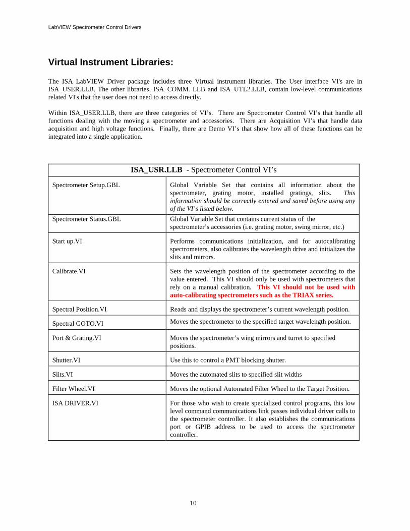
Virtual Instrument Libraries: The ISA LabVIEW Driver package includes three Virtual instrument libraries. The User interface VI's are in ISA_USER.LLB. The other libraries, ISA_COMM. LLB and ISA_UTL2.LLB, contain low-level communications related VI's that the user does not need to access directly. Within ISA_USER.LLB, there are three categories of VI’s. There are Spectrometer Control VI’s that handle all functions dealing with the moving a spectrometer and accessories. There are Acquisition VI’s that handle data acquisition and high voltage functions. Finally, there are Demo VI’s that show how all of these functions can be integrated into a single application.
ISA_USR.LLB - Spectrometer Control VI’s Spectrometer Setup.GBL
Global Variable Set that contains all information about the spectrometer, grating motor, installed gratings, slits. This information should be correctly entered and saved before using any of the VI’s listed below.
Spectrometer Status.GBL Global Variable Set that contains current status of the spectrometer’s accessories (i.e. grating motor, swing mirror, etc.)
Start up.VI
Performs communications initialization, and for autocalibrating spectrometers, also calibrates the wavelength drive and initializes the slits and mirrors.
Calibrate.VI
Sets the wavelength position of the spectrometer according to the value entered. This VI should only be used with spectrometers that rely on a manual calibration. This VI should not be used with auto-calibrating spectrometers such as the TRIAX series.
Spectral Position.VI
Reads and displays the spectrometer’s current wavelength position.
Spectral GOTO.VI Moves the spectrometer to the specified target wavelength position. Port & Grating.VI
Moves the spectrometer’s wing mirrors and turret to specified positions.
Shutter.VI
Use this to control a PMT blocking shutter.
Slits.VI
Moves the automated slits to specified slit widths
Filter Wheel.VI
Moves the optional Automated Filter Wheel to the Target Position.
ISA DRIVER.VI
For those who wish to create specialized control programs, this low level command communications link passes individual driver calls to the spectrometer controller. It also establishes the communications port or GPIB address to be used to access the spectrometer controller.

11
The VI’s for Single Channel Data acquisition will work only with a DataScan, or SpectrAcq type controller.
ISA_USR.LLB - Acquisition VI’s Detector Setup.GBL
Global Variable Set that contains all information about the communication settings for the acquisition electronics and the parameters for the acquisition channel. This information should be correctly entered and saved before using any of the VI’s listed below.
High Voltage Setup.GBL
Global Variable Set that contains all information about the communication settings for the high voltage electronics. This information should be correctly entered and saved before using any of the VI’s listed below.
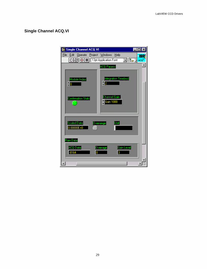
Single Channel ACQ.VI
Reads data from a Single Data Channel
Dual Channel ACQ.VI
Reads data from Two Data Channels. This VI can not be used with a SpectrAcq2.
High Voltage.VI Sets the computer controlled High Voltage.
ISA_USR.LLB - Demonstration VI’s
Spectrometer Control Demo.VI
VI that shows the proper procedure to establish communications with a spectrometer and control all motors and accessories with sub-VI’s.
Scan Demo.VI VI that shows how to perform a single channel acquisition scan.
LabVIEW Spectrometer Control Drivers
12
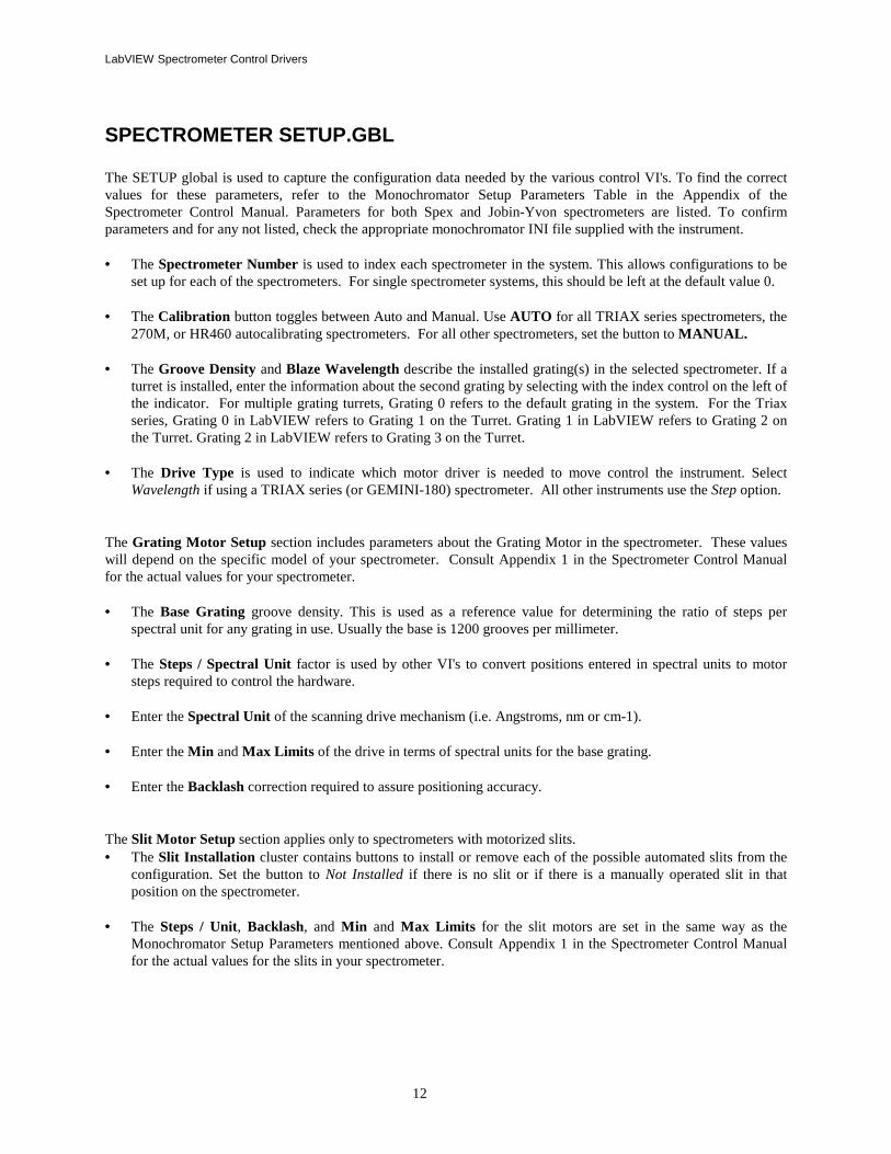
SPECTROMETER SETUP.GBL The SETUP global is used to capture the configuration data needed by the various control VI's. To find the correct values for these parameters, refer to the Monochromator Setup Parameters Table in the Appendix of the Spectrometer Control Manual. Parameters for both Spex and Jobin-Yvon spectrometers are listed. To confirm parameters and for any not listed, check the appropriate monochromator INI file supplied with the instrument. • The Spectrometer Number is used to index each spectrometer in the system. This allows configurations to be
set up for each of the spectrometers. For single spectrometer systems, this should be left at the default value 0. • The Calibration button toggles between Auto and Manual. Use AUTO for all TRIAX series spectrometers, the
270M, or HR460 autocalibrating spectrometers. For all other spectrometers, set the button to MANUAL. • The Groove Density and Blaze Wavelength describe the installed grating(s) in the selected spectrometer. If a
turret is installed, enter the information about the second grating by selecting with the index control on the left of the indicator. For multiple grating turrets, Grating 0 refers to the default grating in the system. For the Triax series, Grating 0 in LabVIEW refers to Grating 1 on the Turret. Grating 1 in LabVIEW refers to Grating 2 on the Turret. Grating 2 in LabVIEW refers to Grating 3 on the Turret.
• The Drive Type is used to indicate which motor driver is needed to move control the instrument. Select
Wavelength if using a TRIAX series (or GEMINI-180) spectrometer. All other instruments use the Step option. The Grating Motor Setup section includes parameters about the Grating Motor in the spectrometer. These values will depend on the specific model of your spectrometer. Consult Appendix 1 in the Spectrometer Control Manual for the actual values for your spectrometer. • The Base Grating groove density. This is used as a reference value for determining the ratio of steps per
spectral unit for any grating in use. Usually the base is 1200 grooves per millimeter. • The Steps / Spectral Unit factor is used by other VI's to convert positions entered in spectral units to motor
steps required to control the hardware. • Enter the Spectral Unit of the scanning drive mechanism (i.e. Angstroms, nm or cm-1). • Enter the Min and Max Limits of the drive in terms of spectral units for the base grating. • Enter the Backlash correction required to assure positioning accuracy. The Slit Motor Setup section applies only to spectrometers with motorized slits. • The Slit Installation cluster contains buttons to install or remove each of the possible automated slits from the
configuration. Set the button to Not Installed if there is no slit or if there is a manually operated slit in that position on the spectrometer.
• The Steps / Unit, Backlash, and Min and Max Limits for the slit motors are set in the same way as the
Monochromator Setup Parameters mentioned above. Consult Appendix 1 in the Spectrometer Control Manual for the actual values for the slits in your spectrometer.
13
The Communications Parameters cluster is used to select the hardware connections to access the Spectrometer control electronics. • The Interface ring control selects the RS-232 serial or IEEE488 GPIB communications hardware. • If GPIB is selected as the interface, the GPIB Bus numeric control determines which of the GPIB interface
cards plugged into the computer is used. • The GPIB Address numeric control sets the address of the spectrometer controller on the Bus. • If the RS-232 Interface is selected, the Serial Com Port control is used to select the serial port connection on
the computer. COM1 = PORT Ø COM2 = PORT 1
Saving Changes in Spectrometer Setup.GBL Once all of the parameters have been set correctly, they must be saved. To save these parameters, first, go to the Operate Menu and choose the Make Current Values Default option. After doing this, go to the File menu and use the Save option to save the changes to the parameters.

LabVIEW Spectrometer Control Drivers
14
Start Up.VI The Start Up.VI must be executed each time the computer or spectrometer controller is powered on. This VI establishes communications with the ISA spectrometer controller and sets it to the proper mode to accept the commands that will follow from the other VI's. • The Max Attempts control sets the number of times the Start Up VI will try to establish communications with
the Spectrometer Controller before returning an error. (Input) • The Error LED is a binary indicator that will turn from green to red when the Start Up VI is unsuccessful in
establishing communications. If failing to communicate, refer to the Computer and LabVIEW manuals for help with connections and settings. (Output)
• The Controller Program Versions Array returns the version numbers of the internal programs that reside in
the spectrometer controller. This information may be helpful when contacting Horiba Jobin Yvon Customer Service for assistance. (Output)

15
Calibrate.VI This VI is used to establish the position of the spectrometer grating drive when the system is initialized. To properly calibrate a spectrometer, the Spectrometer Setup Global must contain the correct base grating, spectral unit, and steps / unit parameters. The Calibrate.VI is used for manually calibrated spectrometers only. (Manually Calibrated spectrometers always have a mechanical counter located in the case of the spectrometer.) The Calibrate VI should be used directly after the Startup VI and before any other VIs are used.
The Calibrate VI should not be used with an Auto-calibrating spectrometer such as the TRIAX series, 270M, or HR460. • The Spectrometer Number selects the spectrometer to be controlled. (Input) • The Counter Position is the reading from the spectrometer's mechanical counter. (Input) • The Spectral Unit indicator returns the working unit according to the Spectrometer Setup. (Output) • The LED Error indicator turns red if there is a communications or out of range error. (Output) • The Invalid Wavelength indicator will turn red if the Target Position entered is outside the bounds defined by
Min and Max Limits entered in the Spectrometer Setup global. (Output)
LabVIEW Spectrometer Control Drivers
16
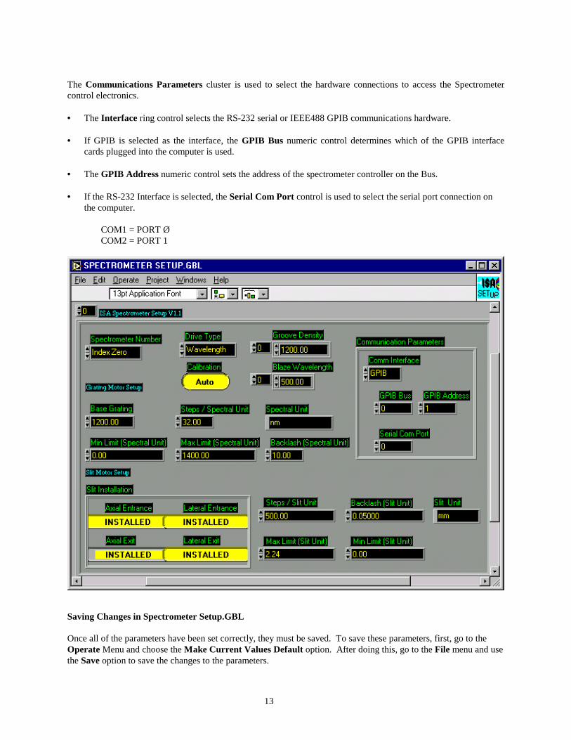
Spectral GOTO.VI The Spectral GOTO.VI is used in nearly all applications. This VI moves the spectrometer to the position entered in the Target position control. • The Spectrometer Number selects the spectrometer to be controlled. (Input) • The Target Position is the wavelength position to which the grating motor will be moved. The Target Position
must be entered in the base units of the spectrometer. (Input) • The Spectral Unit indicator returns the working unit according to the Spectrometer Setup. (Output) • The LED Error indicator turns red if there is an error preventing the VI from repositioning the spectrometer
drive as requested. (Output) • The Limits Hit indicator will turn red if the Spectrometer grating drive mechanism travels to an extreme
position, sensed by a limit switch. (Output) • The Invalid Wavelength indicator will turn red if the Target Position entered is outside the bounds defined by
Min and Max Limits entered in the Spectrometer Setup global. (Output) • The Motor Busy indicator turns red if the spectrometer's motor drive is in the process of repositioning, and
cannot presently accept a new command to move. (Output)

17
Spectral Position.VI The Spectral Position.VI returns the present position of the spectrometer's grating drive. The parameters for this VI include: • The Spectrometer Number of the selected spectrometer. (Input) • The Present Position for the selected spectrometer. (Output) • The Spectral Unit indicator returns the working unit (i.e. Nanometers or Wavenumbers). (Output) • An LED Error indicator will turn red if there is a communications failure. (Output)
LabVIEW Spectrometer Control Drivers
18
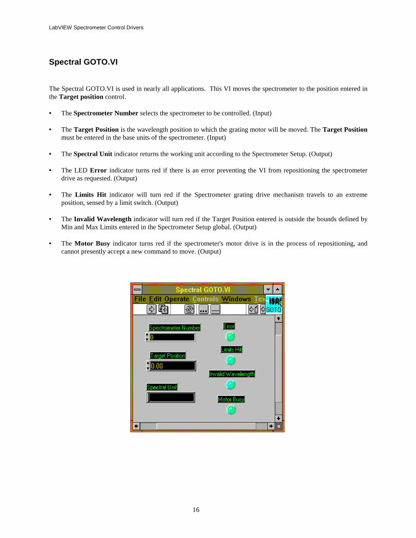
Port and Grating.VI The Port & Grating VI allows the user to control the swing mirrors and grating turret in an automated spectrometer that has those options installed. The front panel settings are as follows: • Spectrometer Number: for multiple spectrometer systems, this selects the particular spectrometer to allow its
mirrors and/ or turret to be positioned. (Input) • The Entrance Mirror Position and Exit Mirror Position buttons toggle between the position of the swing
mirrors. Axial refers to the front port of the spectrometer and Lateral refers to the Side port of the spectrometer. (Input)
• Turret Position: Used to select the grating turret position. As defined by the Spectrometer Setup GBL, Grating
0 refers to the default grating in the system. For the Triax series, Grating 0 in LabVIEW refers to Grating 1 on the Turret. Grating 1 in LabVIEW refers to Grating 2 on the Turret. Grating 2 in LabVIEW refers to Grating 3 on the Turret. (Input)
• Groove Density and Blaze Wavelength indicators for the selected grating will be updated when the VI is
executed. (Output) • An LED Error indicator will turn red if there is a communications failure. (Output) Note that when a port mirror moves, the shutter (if any) associated with the slit selected becomes active. The shutter (if any) associated with the deselected port becomes inactive, and defaults to closed.

19
Shutter.VI Shutter.VI provides for control of interfaced shutters in the system. • The Spectrometer Number selects the spectrometer to be accessed for shutter control. (Input) • The Shutter Position button toggles the active shutter open or closed. (Input) • An LED Error indicator will turn red if there is a communications failure. (Output)
LabVIEW Spectrometer Control Drivers
20
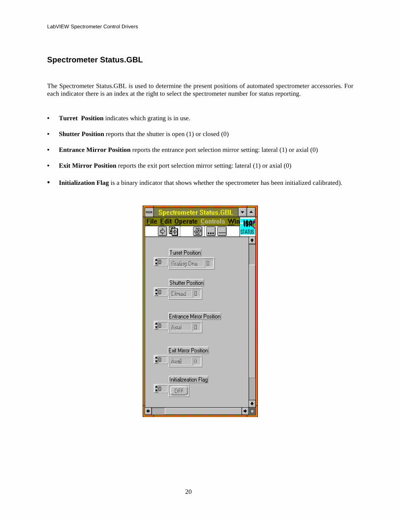
Spectrometer Status.GBL The Spectrometer Status.GBL is used to determine the present positions of automated spectrometer accessories. For each indicator there is an index at the right to select the spectrometer number for status reporting. • Turret Position indicates which grating is in use. • Shutter Position reports that the shutter is open (1) or closed (0) • Entrance Mirror Position reports the entrance port selection mirror setting: lateral (1) or axial (0) • Exit Mirror Position reports the exit port selection mirror setting: lateral (1) or axial (0)
• Initialization Flag is a binary indicator that shows whether the spectrometer has been initialized calibrated).
21
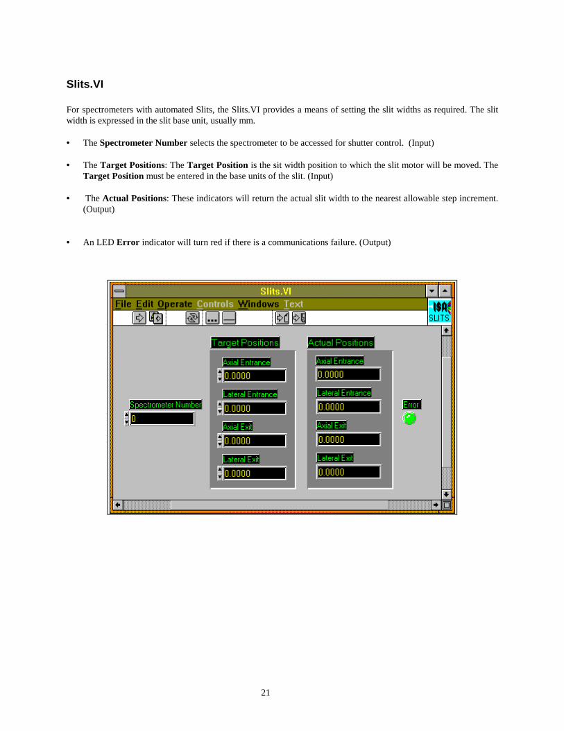
Slits.VI For spectrometers with automated Slits, the Slits.VI provides a means of setting the slit widths as required. The slit width is expressed in the slit base unit, usually mm. • The Spectrometer Number selects the spectrometer to be accessed for shutter control. (Input) • The Target Positions: The Target Position is the sit width position to which the slit motor will be moved. The
Target Position must be entered in the base units of the slit. (Input) • The Actual Positions: These indicators will return the actual slit width to the nearest allowable step increment.
(Output) • An LED Error indicator will turn red if there is a communications failure. (Output)
LabVIEW Spectrometer Control Drivers
22
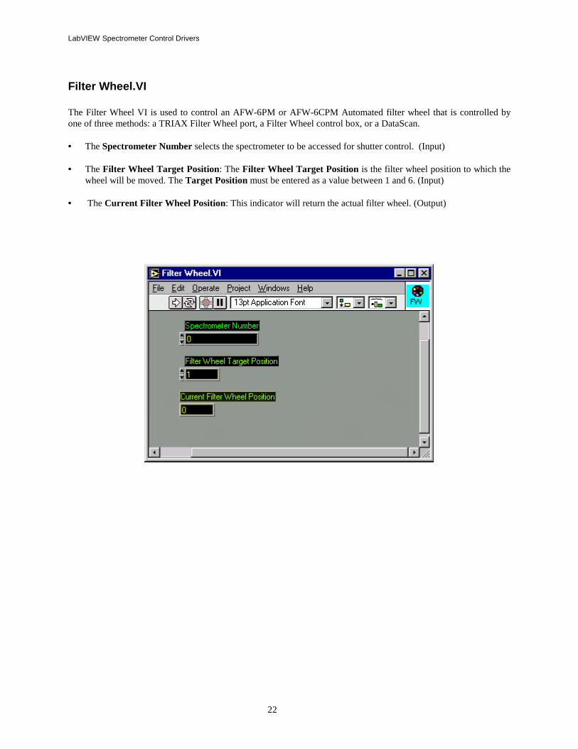
Filter Wheel.VI The Filter Wheel VI is used to control an AFW-6PM or AFW-6CPM Automated filter wheel that is controlled by one of three methods: a TRIAX Filter Wheel port, a Filter Wheel control box, or a DataScan. • The Spectrometer Number selects the spectrometer to be accessed for shutter control. (Input) • The Filter Wheel Target Position: The Filter Wheel Target Position is the filter wheel position to which the
wheel will be moved. The Target Position must be entered as a value between 1 and 6. (Input) • The Current Filter Wheel Position: This indicator will return the actual filter wheel. (Output)
23
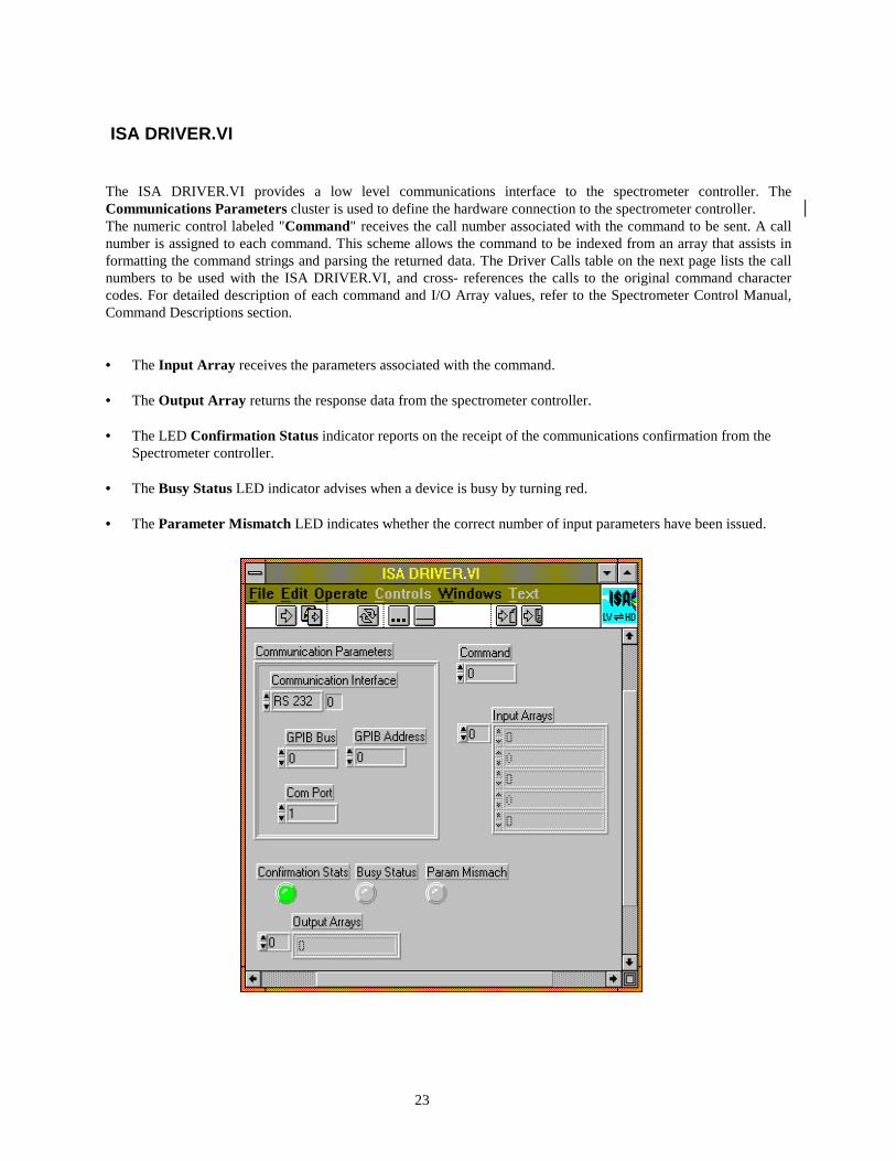
ISA DRIVER.VI The ISA DRIVER.VI provides a low level communications interface to the spectrometer controller. The Communications Parameters cluster is used to define the hardware connection to the spectrometer controller. The numeric control labeled "Command" receives the call number associated with the command to be sent. A call number is assigned to each command. This scheme allows the command to be indexed from an array that assists in formatting the command strings and parsing the returned data. The Driver Calls table on the next page lists the call numbers to be used with the ISA DRIVER.VI, and cross- references the calls to the original command character codes. For detailed description of each command and I/O Array values, refer to the Spectrometer Control Manual, Command Descriptions section. • The Input Array receives the parameters associated with the command. • The Output Array returns the response data from the spectrometer controller. • The LED Confirmation Status indicator reports on the receipt of the communications confirmation from the
Spectrometer controller. • The Busy Status LED indicator advises when a device is busy by turning red. • The Parameter Mismatch LED indicates whether the correct number of input parameters have been issued.
LabVIEW Spectrometer Control Drivers
24
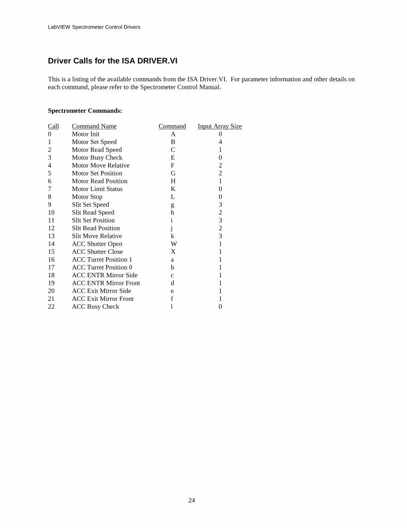
Driver Calls for the ISA DRIVER.VI This is a listing of the available commands from the ISA Driver.VI. For parameter information and other details on each command, please refer to the Spectrometer Control Manual. Spectrometer Commands: Call Command Name Command Input Array Size 0 Motor Init A 0 1 Motor Set Speed B 4 2 Motor Read Speed C 1 3 Motor Busy Check E 0 4 Motor Move Relative F 2 5 Motor Set Position G 2 6 Motor Read Position H 1 7 Motor Limit Status K 0 8 Motor Stop L 0 9 Slit Set Speed g 3 10 Slit Read Speed h 2 11 Slit Set Position i 3 12 Slit Read Position j 2 13 Slit Move Relative k 3 14 ACC Shutter Open W 1 15 ACC Shutter Close X 1 16 ACC Turret Position 1 a 1 17 ACC Turret Position 0 b 1 18 ACC ENTR Mirror Side c 1 19 ACC ENTR Mirror Front d 1 20 ACC Exit Mirror Side e 1 21 ACC Exit Mirror Front f 1 22 ACC Busy Check l 0

25
Data Acquisition Commands: Call Command Name Command Input Array Size 23 ACQ Measure Offsets w 1 24 ACQ Set Offsets x 5 25 ACQ Channel Gain Set R 2 26 ACQ Gain Read S 1 27 ACQ Integration Time Set O 2 28 ACQ Integration Time Read P 1 29 ACQ Start M 1 30 ACQ Stop N 0 31 ACQ Busy Q 0 32 ACQ Read Data T 1 33 High Voltage Set U 2 34 High Voltage Read V 1 35 TTL Write Output m 1 36 TTL Read Output n 0 37 TTL Read Input o 0 38 TTL Automatic Outputs Z11 8 39 Threshold Write Value I 4 40 Threshold Read Values J 0 41 Scan Set Parameters p 19 42 Scan Start q 0 43 Scan Stop v 0 44 Scan Current Status r 0 45 Scan Cycle to Read s 1 46 Scan Get Data Point No. t 0 47 Scan Get Data u 1 TRIAX Only Commands: Call Command Name Command Input Array Size 48 Wavelength Move Z61 2 49 Read Wavelength Position Z62 1 50 Define Wavelength Position Z60 2 51 Index Device Set Position Z451 4 52 Index Device Read Position Z452 3 53 Index Device Status Z453 3 Filter Wheel Commands: Call Command Name Command Input Array Size 54 Filter Wheel Move Position Z3 2 55 Filter Wheel Read Position Z4 1 56 Filter Wheel Busy Test Z5 0
26
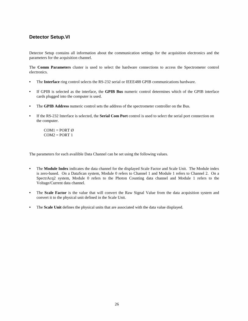
Detector Setup.VI Detector Setup contains all information about the communication settings for the acquisition electronics and the parameters for the acquisition channel. The Comm Parameters cluster is used to select the hardware connections to access the Spectrometer control electronics. • The Interface ring control selects the RS-232 serial or IEEE488 GPIB communications hardware. • If GPIB is selected as the interface, the GPIB Bus numeric control determines which of the GPIB interface
cards plugged into the computer is used. • The GPIB Address numeric control sets the address of the spectrometer controller on the Bus. • If the RS-232 Interface is selected, the Serial Com Port control is used to select the serial port connection on
the computer. COM1 = PORT Ø COM2 = PORT 1 The parameters for each availible Data Channel can be set using the following values. • The Module Index indicates the data channel for the displayed Scale Factor and Scale Unit. The Module index
is zero-based. On a DataScan system, Module 0 refers to Channel 1 and Module 1 refers to Channel 2. On a SpectrAcq2 system, Module 0 refers to the Photon Counting data channel and Module 1 refers to the Voltage/Current data channel.
• The Scale Factor is the value that will convert the Raw Signal Value from the data acquisition system and
convert it to the physical unit defined in the Scale Unit. • The Scale Unit defines the physical units that are associated with the data value displayed.
LabVIEW CCD Drivers
27
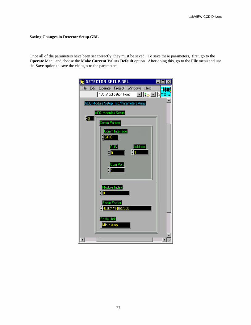
Saving Changes in Detector Setup.GBL Once all of the parameters have been set correctly, they must be saved. To save these parameters, first, go to the Operate Menu and choose the Make Current Values Default option. After doing this, go to the File menu and use the Save option to save the changes to the parameters.
LabVIEW CCD Drivers
28
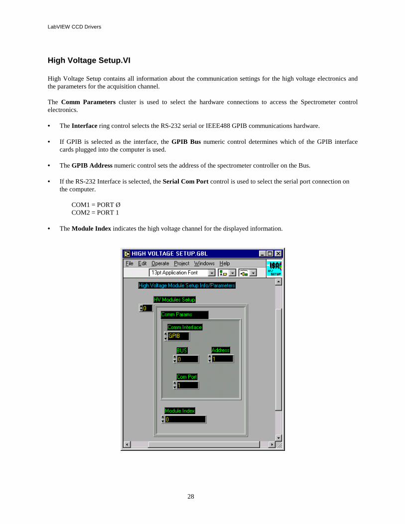
High Voltage Setup.VI High Voltage Setup contains all information about the communication settings for the high voltage electronics and the parameters for the acquisition channel. The Comm Parameters cluster is used to select the hardware connections to access the Spectrometer control electronics. • The Interface ring control selects the RS-232 serial or IEEE488 GPIB communications hardware. • If GPIB is selected as the interface, the GPIB Bus numeric control determines which of the GPIB interface
cards plugged into the computer is used. • The GPIB Address numeric control sets the address of the spectrometer controller on the Bus. • If the RS-232 Interface is selected, the Serial Com Port control is used to select the serial port connection on
the computer. COM1 = PORT Ø COM2 = PORT 1 • The Module Index indicates the high voltage channel for the displayed information.
LabVIEW CCD Drivers
29
Single Channel ACQ.VI

LabVIEW CCD Drivers
30
LabVIEW CCD Drivers
31
LabVIEW Drivers for CCD-3000 systems: Note: The CCD-3000 series of detectors are still supported under SynerJY software and LabVIEW up to version 8.5. VIs for CCD-2000 and earlier CCDs are no longer supported. ICCDs are not supported.
System Requirements: • An IBM compatible running National Instruments’ LabVIEW® version 4 – 8.5* • The computer must be have a CCD-3000 or -3500 controller with a National Instruments IEEE488 card. • To use the Instrument SA (SPEX or Jobin-Yvon) spectrometer control LabVIEW® drivers, the spectrometer
must be equipped with a SPEX232, SPEX488, JY232, or JY488 spectrometer interface or the DataLink, DataScan, or SpectrAcq spectrometer controller.
*If using LabVIEW 4.0, it must be installed as the 16-bit version (Windows 3.11). The DLL files for the CCD controller will only interface with the 16-bit version.
Installation: The LabVIEW drivers for CCD control are virtually self-installing. Copy them from the CSW-LVW CD-ROM onto the PC desktop. LEGACY--
• CCD 3000 controller has GPIB communication capability only and is hardcoded as dev 5. • When prompted, enter the information regarding the IEEE-488 device number then click OK to
confirm. The program will complete the installation and an option to access the ReadMe file will be presented to the screen. Any last minute changes to the software or other valuable information is contained in this file.
LabVIEW CCD Drivers
32
Virtual Instrument Libraries: The ISA LabVIEW Driver package includes one Virtual instrument library. Some example interface VI's are in default directory. The library, ISA_CCDVI. LLB, contains the individual VI's that control different portions of the CCD operation. ISACCDVI.LLB CCDREAD.VI This VI retrieves a 2D array of CCD data from the specified region CCDBUSY.VI CCD Busy, Check if a CCD acquisition is in progress. CCDError.VI Use this VI to decode the numeric error codes given. CCDGO.VI Starts the CCD acquisition with the given region(s) defined in RGNSET.VI. CCDSTOP.VI Use this VI to halt a CCD acquisition in progress. OpenCCD.VI Load and open the CCD driver DLL with the given parameters. PROPGET.VI This VI returns requested information relevant to the operation of the CCD. The
available properties are listed in README.VI PROPSET.VI ReadMe.VI VI containing text file with CCD Properties (See Below) RGNSET.VI Use this VI to define all of the active acquisition regions within the CCD chip. From ISACCD Directory TestDEV.VI This VI demonstrates acquisition and image display of CCD data utilizing the ISA
CCD driver. Note: Specific help is available for each individual control, display and indicator.
TempMON.VI Monitors the temperature.
Operation: If using the CCD2000 controller, before calling any VI, run the HWINIT.BAT program to initialize the CCD2000 controller. The CCD3000 controller does not require any hardware initialization.
Supported IEEE 488 Computer Interface Boards (CCD3000 Only): The IEEE 488 example programs work with several of the National Instruments PC interface boards.
• GPIB-PCII/PCIIA 488.2 Interface board: The driver supplied by National should be version 1.2 or newer, and their BASIC support disk should be version 2. /0 or newer.
• Older GPIB-PCIIA boards require National's revision C13 or newer software.
• AT-GPIB 488 boards require National's revision E7 or newer software.
• AT-GPIB 488.2 board: Must be version 2.7.0 software, and their BASIC support disk version 2.2 or newer.
• GPIB-PCIII board: this model must be replaced with one of the above. Contact your local National Instruments dealer with regard to their current replacement program.
There are other boards by National and other suppliers for IBM computers. Many of these boards can function in SIMILAR fashion, however the drivers communicate specifically with the National Instruments drivers therefore we do not support or guarantee reliable communications with other boards and software, you must use the National Instruments products as described above or newer versions of the same. Apple of Macintosh versions of VIs from the 1990’s are NOT SUPPORTED!
LabVIEW CCD Drivers
33
Establishing GPIB Communications (CCD3000 Only): The IEEE board and it's associated software driver must be installed in your computer as per National Instruments' instructions. The driver must be installed via your computer's CONFIG.SYS file. This set up assumes that the National Instruments software driver has the PCII board name as GPIB/0 and the first device name as DEV1. Run the IBCONF program and set the configuration as follows: GPIB /0 Primary GPIB Address /0 Secondary GPIB Address None Timeout Setting T3s EOS byte /0 /0H Terminate read on EOS no Set EOI with EOS on write no Type of compare on EOS 7-bit Set EOI w/ last byte of write yes System controller yes Assert REN when SC no Enable auto serial polling yes Timing 5 /0 /0 ns Enable 488.2 protocols yes CIC protocols no Handler Type PC2 Interrupt Setting none Base I/O address /02B8H DMA channel 1
DEV5 Primary GPIB address 5 Secondary GPIB address None Timeout Setting T1/0s EOS byte /0Dh Terminate read on EOS yes Set EOI with EOS on write no Type of compare on EOS 7-bit Set EOI w/ last byte of write yes Repeat addressing no (The above are the default settings)
34
General Notes:
Changes made to SYSTEM.INI
Here is an example section from a valid system.ini file: [ISA CCD Driver] debugflags=0 path=c:\labview\isaccd\ port=3616 dma=1 irq=5 Emulation
Sound Cards and CD-ROM drives: Many sound card and CD-ROM controllers use IRQ 5 as the default setting. This causes a conflict with the CCD data acquisition board in the CCD2000. Change the IRQ address of the sound card or consult the SpectrumONE manual on how to change the address on the CCD card. If you change the address on the CCD card you must change the setting in the SYSTEM.INI or reinstall the software with the new IRQ.
Error Codes: DLL Handle = 0 DLL can’t be found DLL Handle ≠ 0 AND API Handle = 0 Incorrect SYSTEM.INI setup Hardware conflict
Cannot find GSRGNIF.LSB This file should be located in the same directory as the ISACCDVI.LLB file.
35
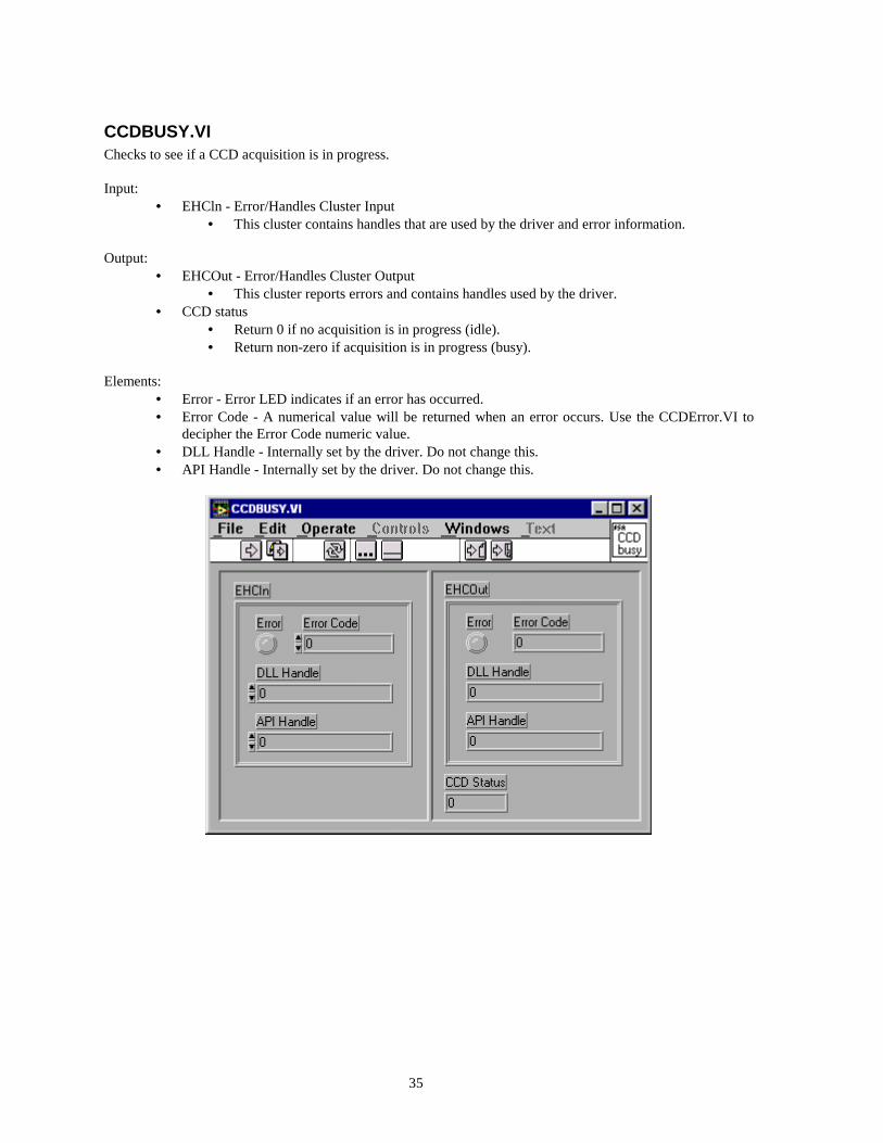
CCDBUSY.VI Checks to see if a CCD acquisition is in progress. Input:
• EHCln - Error/Handles Cluster Input • This cluster contains handles that are used by the driver and error information.
Output:
• EHCOut - Error/Handles Cluster Output • This cluster reports errors and contains handles used by the driver.
• CCD status • Return 0 if no acquisition is in progress (idle). • Return non-zero if acquisition is in progress (busy).
Elements:
• Error - Error LED indicates if an error has occurred. • Error Code - A numerical value will be returned when an error occurs. Use the CCDError.VI to
decipher the Error Code numeric value. • DLL Handle - Internally set by the driver. Do not change this. • API Handle - Internally set by the driver. Do not change this.

36
CCDError.VI Use this VI to decode the numeric error codes given Input:
• EHCln - Error/Handles Cluster Input • This cluster contains handles that are used by the driver and error information.
Output:
• EHCOut - Error/Handles Cluster Output • This cluster reports errors and contains handles used by the driver.
• Error • Error LED indicates if an error has occurred.
• Description • Plane text error message.
Elements:
• Error - Error LED indicates if an error has occurred. • Error Code - A numerical value will be returned when an error occurs. Use the CCDError.VI to
decipher the Error Code numeric value. • DLL Handle - Internally set by the driver. Do not change this. • API Handle - Internally set by the driver. Do not change this.
37
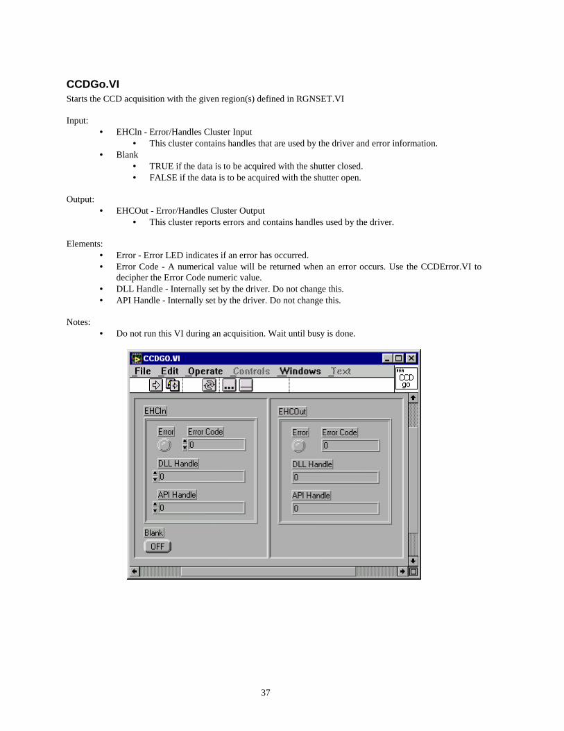
CCDGo.VI Starts the CCD acquisition with the given region(s) defined in RGNSET.VI Input:
• EHCln - Error/Handles Cluster Input • This cluster contains handles that are used by the driver and error information.
• Blank • TRUE if the data is to be acquired with the shutter closed. • FALSE if the data is to be acquired with the shutter open.
Output:
• EHCOut - Error/Handles Cluster Output • This cluster reports errors and contains handles used by the driver.
Elements:
• Error - Error LED indicates if an error has occurred. • Error Code - A numerical value will be returned when an error occurs. Use the CCDError.VI to
decipher the Error Code numeric value. • DLL Handle - Internally set by the driver. Do not change this. • API Handle - Internally set by the driver. Do not change this.
Notes:
• Do not run this VI during an acquisition. Wait until busy is done.
38
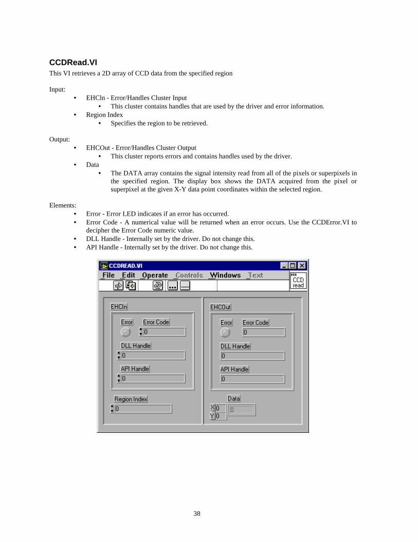
CCDRead.VI This VI retrieves a 2D array of CCD data from the specified region Input:
• EHCln - Error/Handles Cluster Input • This cluster contains handles that are used by the driver and error information.
• Region Index • Specifies the region to be retrieved.
Output:
• EHCOut - Error/Handles Cluster Output • This cluster reports errors and contains handles used by the driver.
• Data • The DATA array contains the signal intensity read from all of the pixels or superpixels in
the specified region. The display box shows the DATA acquired from the pixel or superpixel at the given X-Y data point coordinates within the selected region.
Elements:
• Error - Error LED indicates if an error has occurred. • Error Code - A numerical value will be returned when an error occurs. Use the CCDError.VI to
decipher the Error Code numeric value. • DLL Handle - Internally set by the driver. Do not change this. • API Handle - Internally set by the driver. Do not change this.

39
CCDStop.VI Use this VI to halt a CCD acquisition. It is important to call this VI for aborting an acquisition. (It resets the internal CCD state machine.) Input:
• EHCln - Error/Handles Cluster Input • This cluster contains handles that are used by the driver and error information.
Output:
• EHCOut - Error/Handles Cluster Output • This cluster reports errors and contains handles used by the driver.
Elements:
• Error - Error LED indicates if an error has occurred. • Error Code - A numerical value will be returned when an error occurs. Use the CCDError.VI to
decipher the Error Code numeric value. • DLL Handle - Internally set by the driver. Do not change this. • API Handle - Internally set by the driver. Do not change this.
40
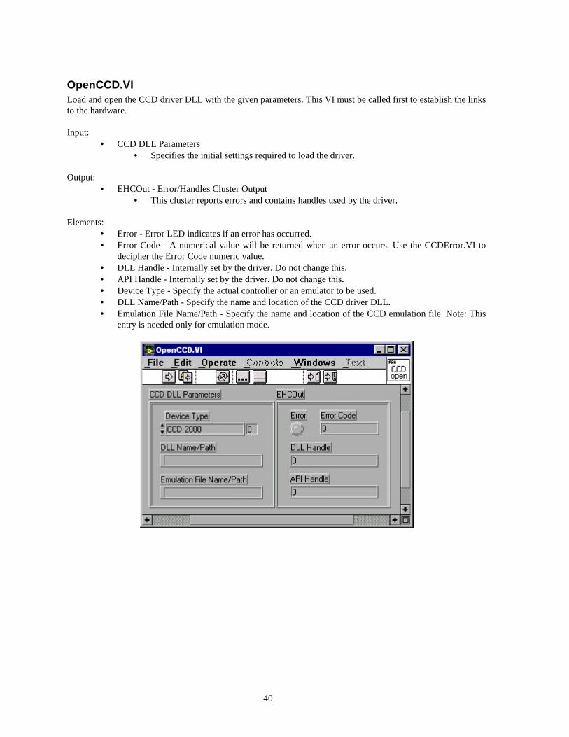
OpenCCD.VI Load and open the CCD driver DLL with the given parameters. This VI must be called first to establish the links to the hardware. Input:
• CCD DLL Parameters • Specifies the initial settings required to load the driver.
Output:
• EHCOut - Error/Handles Cluster Output • This cluster reports errors and contains handles used by the driver.
Elements:
• Error - Error LED indicates if an error has occurred. • Error Code - A numerical value will be returned when an error occurs. Use the CCDError.VI to
decipher the Error Code numeric value. • DLL Handle - Internally set by the driver. Do not change this. • API Handle - Internally set by the driver. Do not change this. • Device Type - Specify the actual controller or an emulator to be used. • DLL Name/Path - Specify the name and location of the CCD driver DLL. • Emulation File Name/Path - Specify the name and location of the CCD emulation file. Note: This
entry is needed only for emulation mode.
41
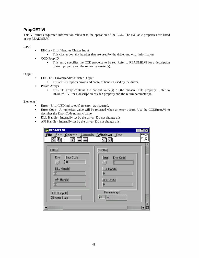
PropGET.VI This VI returns requested information relevant to the operation of the CCD. The available properties are listed in the README.VI Input:
• EHCln - Error/Handles Cluster Input • This cluster contains handles that are used by the driver and error information.
• CCD Prop ID • This entry specifies the CCD property to be set. Refer to README.VI for a description
of each property and the return parameter(s). Output:
• EHCOut - Error/Handles Cluster Output • This cluster reports errors and contains handles used by the driver.
• Param Arrays • This 1D array contains the current value(s) of the chosen CCD property. Refer to
README.VI for a description of each property and the return parameter(s). Elements:
• Error - Error LED indicates if an error has occurred. • Error Code - A numerical value will be returned when an error occurs. Use the CCDError.VI to
decipher the Error Code numeric value. • DLL Handle - Internally set by the driver. Do not change this. • API Handle - Internally set by the driver. Do not change this.
42
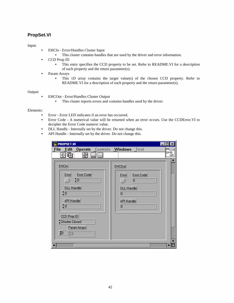
PropSet.VI Input:
• EHCln - Error/Handles Cluster Input • This cluster contains handles that are used by the driver and error information.
• CCD Prop ID • This entry specifies the CCD property to be set. Refer to README.VI for a description
of each property and the return parameter(s). • Param Arrays
• This 1D array contains the target value(s) of the chosen CCD property. Refer to README.VI for a description of each property and the return parameter(s).
Output:
• EHCOut - Error/Handles Cluster Output • This cluster reports errors and contains handles used by the driver.
Elements:
• Error - Error LED indicates if an error has occurred. • Error Code - A numerical value will be returned when an error occurs. Use the CCDError.VI to
decipher the Error Code numeric value. • DLL Handle - Internally set by the driver. Do not change this. • API Handle - Internally set by the driver. Do not change this.
43
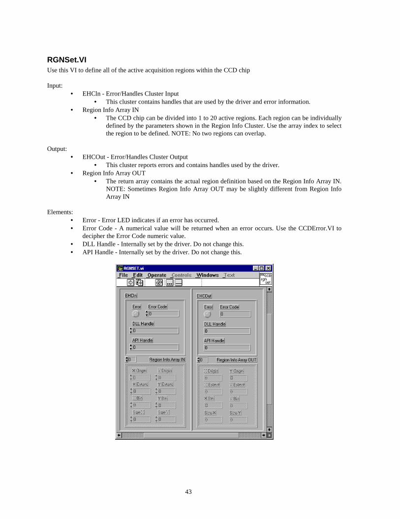
RGNSet.VI Use this VI to define all of the active acquisition regions within the CCD chip Input:
• EHCln - Error/Handles Cluster Input • This cluster contains handles that are used by the driver and error information.
• Region Info Array IN • The CCD chip can be divided into 1 to 20 active regions. Each region can be individually
defined by the parameters shown in the Region Info Cluster. Use the array index to select the region to be defined. NOTE: No two regions can overlap.
Output:
• EHCOut - Error/Handles Cluster Output • This cluster reports errors and contains handles used by the driver.
• Region Info Array OUT • The return array contains the actual region definition based on the Region Info Array IN.
NOTE: Sometimes Region Info Array OUT may be slightly different from Region Info Array IN
Elements:
• Error - Error LED indicates if an error has occurred. • Error Code - A numerical value will be returned when an error occurs. Use the CCDError.VI to
decipher the Error Code numeric value. • DLL Handle - Internally set by the driver. Do not change this. • API Handle - Internally set by the driver. Do not change this.

44
TestDev.VI This VI demonstrates acquisition and image display of CCD data utilizing the ISA CCD driver. Note: Specific help is available for each individual control, display and indicator.
45
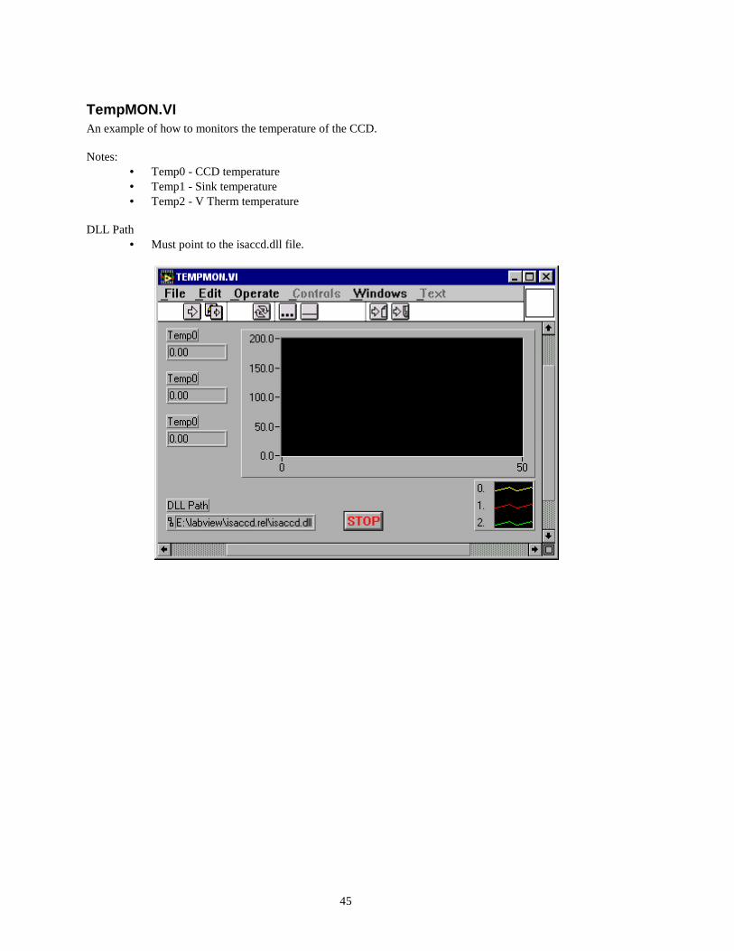
TempMON.VI An example of how to monitors the temperature of the CCD. Notes:
• Temp0 - CCD temperature • Temp1 - Sink temperature • Temp2 - V Therm temperature
DLL Path
• Must point to the isaccd.dll file.
46
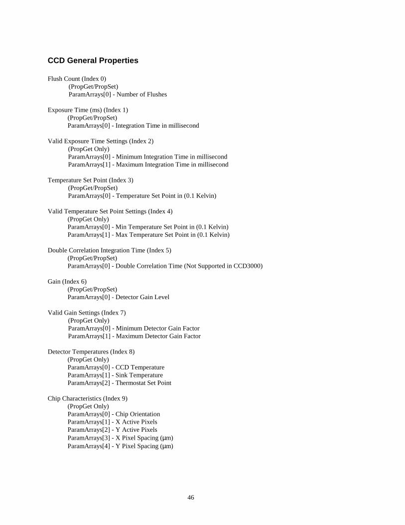
CCD General Properties Flush Count (Index 0) (PropGet/PropSet) ParamArrays[0] - Number of Flushes Exposure Time (ms) (Index 1)
(PropGet/PropSet) ParamArrays[0] - Integration Time in millisecond
Valid Exposure Time Settings (Index 2)
(PropGet Only) ParamArrays[0] - Minimum Integration Time in millisecond ParamArrays[1] - Maximum Integration Time in millisecond
Temperature Set Point (Index 3)
(PropGet/PropSet) ParamArrays[0] - Temperature Set Point in (0.1 Kelvin)
Valid Temperature Set Point Settings (Index 4)
(PropGet Only) ParamArrays[0] - Min Temperature Set Point in (0.1 Kelvin) ParamArrays[1] - Max Temperature Set Point in (0.1 Kelvin)
Double Correlation Integration Time (Index 5)
(PropGet/PropSet) ParamArrays[0] - Double Correlation Time (Not Supported in CCD3000)
Gain (Index 6)
(PropGet/PropSet) ParamArrays[0] - Detector Gain Level
Valid Gain Settings (Index 7)
(PropGet Only) ParamArrays[0] - Minimum Detector Gain Factor ParamArrays[1] - Maximum Detector Gain Factor
Detector Temperatures (Index 8)
(PropGet Only) ParamArrays[0] - CCD Temperature ParamArrays[1] - Sink Temperature ParamArrays[2] - Thermostat Set Point
Chip Characteristics (Index 9)
(PropGet Only) ParamArrays[0] - Chip Orientation ParamArrays[1] - X Active Pixels ParamArrays[2] - Y Active Pixels ParamArrays[3] - X Pixel Spacing (µm) ParamArrays[4] - Y Pixel Spacing (µm)
47
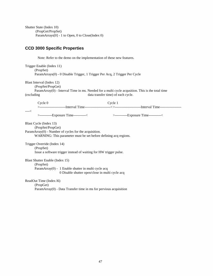
Shutter State (Index 10) (PropGet/PropSet) ParamArrays[0] - 1 to Open, 0 to Close(Index 0)
CCD 3000 Specific Properties Note: Refer to the demo on the implementation of these new features. Trigger Enable (Index 11) (PropSet) ParamArrays(0) - 0 Disable Trigger, 1 Trigger Per Acq, 2 Trigger Per Cycle Blast Interval (Index 12) (PropSet/PropGet) ParamArray(0) - Interval Time in ms. Needed for a multi cycle acqusition. This is the total time (excluding data transfer time) of each cycle. Cycle 0 Cycle 1 >-----------------------Interval Time-----------------------< >-----------------------Interval Time-----------------------< >-----------Exposure Time-----------< >-----------Exposure Time-----------< Blast Cycle (Index 13) (PropSet/PropGet) ParamArray(0) - Number of cycles for the acquisition. WARNING: This parameter must be set before defining acq regions. Trigger Override (Index 14) (PropSet) Issue a software trigger instead of waiting for HW trigger pulse. Blast Shutter Enable (Index 15) (PropSet) ParamArray(0) - 1 Enable shutter in multi cycle acq 0 Disable shutter open/close in multi cycle acq ReadOut Time (Index l6) (PropGet) ParamArray(0) - Data Transfer time in ms for pervious acquisition
48
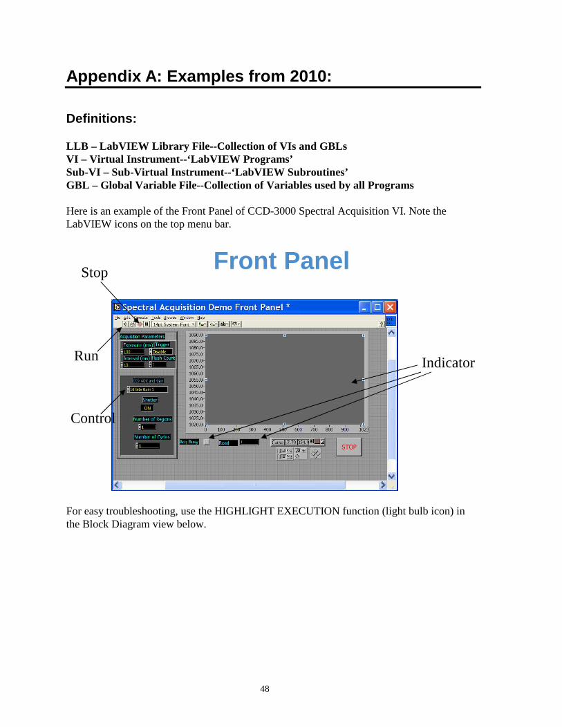
Appendix A: Examples from 2010:
Definitions:
LLB – LabVIEW Library File--Collection of VIs and G BLs VI – Virtual Instrument--‘LabVIEW Programs’ Sub-VI – Sub-Virtual Instrument--‘LabVIEW Subroutin es’ GBL – Global Variable File--Collection of Variables used by all Programs Here is an example of the Front Panel of CCD-3000 Spectral Acquisition VI. Note the LabVIEW icons on the top menu bar.
For easy troubleshooting, use the HIGHLIGHT EXECUTION function (light bulb icon) in the Block Diagram view below.
Front Panel Stop
Run
Control
Indicator

49
It is of utmost importance to configure the parameters correctly in Spectrometer Setup.GBL.
As of this writing, the Triax, Gemini and FHR series (electronics and wavelength drive similar to Triax) are the only spectrometers sold by Horiba Jobin Yvon (formerly ISA) that use GPIB and RS-232 communications. They all have AUTO-CALIBRATING wavelength
drives, and must be configured this way. (A new M-Series (II) using USB communication has replaced the old SPEX instruments, and is described in a separate manual.)
Block Diagram
Stop
Run
Highlight Execution
50
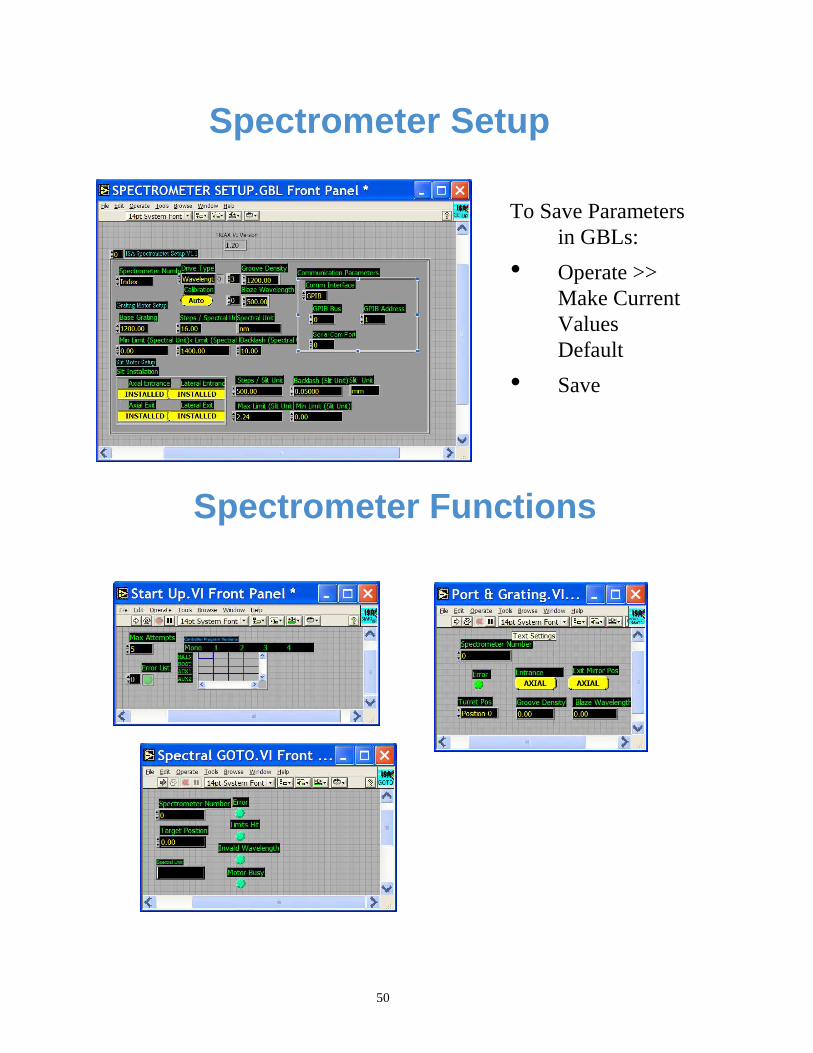
Spectrometer Setup
To Save Parameters in GBLs:
• Operate >> Make Current Values Default
• Save
Spectrometer Functions
51
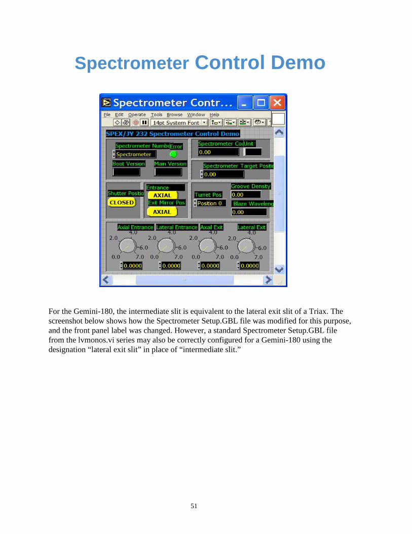
For the Gemini-180, the intermediate slit is equivalent to the lateral exit slit of a Triax. The screenshot below shows how the Spectrometer Setup.GBL file was modified for this purpose, and the front panel label was changed. However, a standard Spectrometer Setup.GBL file from the lvmonos.vi series may also be correctly configured for a Gemini-180 using the designation “lateral exit slit” in place of “intermediate slit.”
Spectrometer Control Demo

52
Service Policy If you need assistance in resolving a problem with your instrument, contact our Customer Service Department directly, or if outside the United States, through our representative or affiliate covering your location.
Often it is possible to correct, reduce, or localize the problem through discussion with our Customer Service Engineers.
All instruments are covered by warranty. The warranty statement is printed on the inside back cover of this manual. Service for out-of-warranty instruments is also available, for a fee. Contact HORIBA Jobin Yvon or your local representative for details and cost estimates.
If your problem relates to software, please verify your computer's operation by running any diagnostic routines that were provided with it. Please refer to the software documentation for troubleshooting procedures. If you must call for Technical Support, please be ready to provide the software serial number, as well as the software version and firmware version of any controller or interface options in your system. The software version can be determined by selecting the software name at the right end of the menu bar and clicking on “About.” Also knowing the memory type and allocation, and other computer hardware configuration data from the PC's CMOS Setup utility may be useful.
In the United States, customers may contact the Customer Service department directly. From other locations worldwide, contact the representative or affiliate for your location. In the USA: HORIBA Jobin Yvon Inc 3880 Park Avenue Edison, NJ 08820-3012 Toll-Free: +1-866-Jobinyvon Tel: +1-732-494-8660 Ext. 160 Fax: +1-732-549-5125 Email: [email protected] www.horiba.com\scientific
In France: HORIBA Jobin Yvon S.A.S 16-18 rue du Canal 91165 Longjumeau cedex Tel: +33 (0) 1 64 54 13 00 Fax: +33 (0) 1 69 09 07 21 www. jobinyvon.fr
In Japan Horiba Ltd., JY Optical Sales Dept. Higashi-Kanda Daiji Building 1-7-8 Higashi-Kanda, Chiyoda-ku Tokyo 101-0031 Tel: +81 (0) 3 3861 8231 www.jyhoriba.jp
Worldwide: 1-877-JYHoriba
China: +86 (0) 10 6849 2216
Germany: +49 (0) 89 4623 17-0
Italy : +39 0 2 57603050
UK : +44 (0) 20 8204 8142
If an instrument or component must be returned, the method described on the following page should be followed to expedite servicing and reduce your downtime.

53
Return Authorization
All instruments and components returned to the factory must be accompanied by a Return Authorization Number issued by our Customer Service Department.
To issue a Return Authorization number, we require:
• The model and serial number of the instrument
• A list of items and/or components to be returned
• A description of the problem, including operating settings
• The instrument user's name, mailing address, telephone, and fax numbers
• The shipping address for shipment of the instrument to you after service
• Your Purchase Order number and billing information for non-warranty services
• Our original Sales Order number, if known
• Your Customer Account number, if known
• Any special instructions

54
Warranty
For any item sold by Seller to Buyer or any repair or service, Seller agrees to repair or replace, without charge to Buyer for labor or materials or workmanship of which Seller is notified in writing before the end of the applicable period set forth below, beginning from the date of shipment or completion of service or repair, whichever is applicable:
a. New equipment, product and laboratory apparatus: 1 year with the following exceptions:
i) Computers and their peripherals
ii) Glassware and glass products.
b. Repairs, replacements, or parts – the greater of 30 days and the remaining original warranty period for the item that was repaired or replaced.
c. Installation services – 90 days.
The above warranties do not cover components manufactured by others and which are separately warranted by the manufacturer. Seller shall cooperate with Buyer in obtaining the benefits of warranties by manufacturers of such items but assumes no obligations with respect thereto.
All defective items replaced pursuant to the above warranty become the property of Seller.
This warranty shall not apply to any components subjected to misuse due to common negligence, adverse environmental conditions, or accident, nor to any components which are not operated in accordance with the printed instructions in the operations manual. Labor, materials and expenses shall be billed to the Buyer at the rates then in effect for any repairs or replacements not covered by this warranty.
This warranty shall not apply to any HORIBA Jobin Yvon manufactured components that have been repaired, altered or installed by anyone not authorized by HORIBA Jobin Yvon in writing.
THE ABOVE WARRANTIES AND ANY OTHER WARRANTIES SET FORTH IN WRITING HERIN ARE IN LIEU OF ALL OTHER WARRANTIES OR GUARANTEES EXPRESSED OR IMPLIED, INCLUDING WARRANTIES OF MERCHANTABILITY, FITNESS FOR PURPOSE OR OTHER WARRANTIES.
The above shall constitute complete fulfillment of all liabilities of Seller, and Seller shall not be liable under any circumstances for special or consequential damages, including without limitation loss of profits or time or personal injury caused.
The limitation on consequential damages set forth above is intended to apply to all aspects of this contract including without limitation Seller’s obligations under these standard terms.

55
Notes

56
Notes


