LAGRANGE: A Space-Based Gravitational-Wave Detector with Geometric Suppression of Spacecraft Noise Mission Concept: Interferometry between three non-drag-free spacecraft in a geometry suppressing non-gravitational effects offers substantial science at significantly reduced cost and risk. We are willing to participate and present the concept at a workshop. This document has been cleared for unlimited release under the number URS225851 Lead Author: Kirk McKenzie ([email protected], Phone: (818) 235 8358) 1 , Co-Authors: Robert E. Spero 1 , William M. Klipstein 1 , Glenn de Vine 1 , Brent Ware 1 , Michele Vallisneri 1 , Curt Cutler 1 , John Ziemer 1 , Daniel A. Shaddock 2 , Ruth Skoug 3 , and John Steinberg 3 1 Jet Propulsion Laboratory, California Institute of Technology, Pasadena, California 2 Department of Physics, The Australian National University, Canberra, Australia 3 Los Alamos National Laboratory, Los Alamos, New Mexico November 10, 2011 Abstract We introduce a new non-drag-free concept for space-based gravitational wave detection in which the space- craft constellation geometry is chosen so the largest spacecraft disturbances are weakly coupled into the science measurement, and existing instruments are used to calibrate these effects. A three spacecraft con- stellation is presented with significant hardware simplifications and reductions in spacecraft mass, power, and size compared with the Laser Interferometer Space Antenna (LISA) mission, while preserving much of the LISA science (see Figure 1). The cost is estimated to be $ 1.1 Billion (FY12 dollars). Earth Sun 16 o 1AU 2φ Lagrange Pt 2 1 2 3 L = 21 million km L Earth’s orbital path L Not to scale 10 -4 10 -3 10 -2 10 -1 10 0 10 -20 10 -19 10 -18 10 -17 10 -16 10 -15 10 -14 10 -13 Frequency [Hz] Strain [1/rtHz] Geometric Suppresion Calibration Spacecraft Acceleration With geometric suppresion Post calibration LISA LAGRANGE LAGRANGE (40cm Telescope) LA 40cm Figure 1: Left: Geometric suppression of spacecraft noise: solar-radiation and solar-wind pressures are orthogonal to the interferometer sensitive axis. Right: While degraded from the LISA sensitivity, this mission is sensitive enough to retain much of the science. 1 Introduction This paper introduces a concept for a space-based laser interferometer gravitational-wave detector that, like the Laser Interferometer Space Antenna (LISA) [1], uses precision laser interferometry between widely 1
Transcript
LAGRANGE: A Space-Based Gravitational-Wave Detector with GeometricSuppression of Spacecraft Noise
Mission Concept: Interferometry between three non-drag-free spacecraft in a geometry suppressingnon-gravitational effects offers substantial science at significantly reduced cost and risk.
We are willing to participate and present the concept at a workshop.This document has been cleared for unlimited release under the number URS225851
Lead Author: Kirk McKenzie ([email protected], Phone: (818) 235 8358)1,Co-Authors: Robert E. Spero1, William M. Klipstein1, Glenn de Vine1, Brent Ware1, Michele Vallisneri1,
Curt Cutler1, John Ziemer1, Daniel A. Shaddock2, Ruth Skoug3, and John Steinberg3
1Jet Propulsion Laboratory, California Institute of Technology, Pasadena, California2Department of Physics, The Australian National University, Canberra, Australia
3Los Alamos National Laboratory, Los Alamos, New Mexico
November 10, 2011
AbstractWe introduce a new non-drag-free concept for space-based gravitational wave detection in which the space-craft constellation geometry is chosen so the largest spacecraft disturbances are weakly coupled into thescience measurement, and existing instruments are used to calibrate these effects. A three spacecraft con-stellation is presented with significant hardware simplifications and reductions in spacecraft mass, power,and size compared with the Laser Interferometer Space Antenna (LISA) mission, while preserving much ofthe LISA science (see Figure 1). The cost is estimated to be $ 1.1 Billion (FY12 dollars).
Earth
Sun
16o
1AU
2!
Lagrange Pt 2
1
2
3
L = 21 million kmL
Earth’s orbital path
L
Not to scale10!4 10!3 10!2 10!1 10010!20
10!19
10!18
10!17
10!16
10!15
10!14
10!13
Frequency [Hz]
Stra
in [1
/rtHz
]
Geometric Suppresion
Calibration
Spacecraft Acceleration
With geometric suppresion
Post calibration
LISA
LAGRANGE
LAGRANGE (40cm Telescope)
LA
40cm
Figure 1: Left: Geometric suppression of spacecraft noise: solar-radiation and solar-wind pressures are orthogonal tothe interferometer sensitive axis. Right: While degraded from the LISA sensitivity, this mission is sensitive enough toretain much of the science.
1 IntroductionThis paper introduces a concept for a space-based laser interferometer gravitational-wave detector that,
like the Laser Interferometer Space Antenna (LISA) [1], uses precision laser interferometry between widely
1
NASA RFI 2011NNH11ZDA019L
Concepts for the NASA Gravitational-Wave MissionLAGRANGE: A Gravitational-Wave Detector with Geometric Suppression of Spacecraft Noise
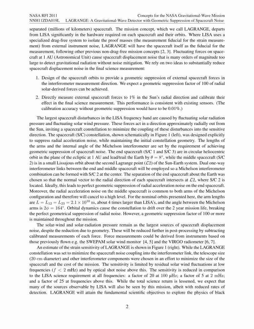
separated (millions of kilometers) spacecraft. The mission concept, which we call LAGRANGE, departsfrom LISA significantly in the hardware required on each spacecraft and their orbits. Where LISA uses aspecialized drag-free system to isolate the proof masses (the measurement fiducial for the strain measure-ment) from external instrument noise, LAGRANGE will have the spacecraft itself as the fiducial for themeasurement, following other previous non-drag-free mission concepts [2, 3]. Fluctuating forces on space-craft at 1 AU (Astronomical Unit) cause spacecraft displacement noise that is many orders of magnitude toolarge to detect gravitational radiation without noise mitigation. We rely on two ideas to substantially reducespacecraft displacement noise in the final science measurement:
1. Design of the spacecraft orbits to provide a geometric suppression of external spacecraft forces inthe interferometer measurement direction. We expect a geometric suppression factor of 100 of radialsolar-derived forces can be achieved.
2. Directly measure external spacecraft forces to 1% in the Sun’s radial direction and calibrate theireffect in the final science measurement. This performance is consistent with existing sensors. (Thecalibration accuracy without geometric suppression would have to be 0.01%.)
The largest spacecraft disturbances in the LISA frequency band are caused by fluctuating solar radiationpressure and fluctuating solar wind pressure. These forces act in a direction approximately radially out fromthe Sun, inviting a spacecraft constellation to minimize the coupling of these disturbances into the sensitivedirection. The spacecraft (S/C) constellation, shown schematically in Figure 1 (left), was designed explicitlyto suppress radial acceleration noise, while maintaining the initial constellation geometry. The lengths ofthe arms and the internal angle of the Michelson interferometer are set by the requirement of achievinggeometric suppression of spacecraft noise. The end spacecraft (S/C 1 and S/C 3) are in circular heliocentricorbit in the plane of the ecliptic at 1 AU and lead/trail the Earth by ! = 8!, while the middle spacecraft (S/C2) is in a small Lissajous orbit about the second Lagrange point (L2) of the Sun-Earth system. Dual one-wayinterferometer links between the end and middle spacecraft will be employed so a Michelson interferometercombination can be formed with S/C 2 at the center. The separation of the end spacecraft about the Earth waschosen so that the normal vector to the radial direction of each spacecraft intersects at L2, where S/C 2 islocated. Ideally, this leads to perfect geometric suppression of radial acceleration noise on the end spacecraft.Moreover, the radial acceleration noise on the middle spacecraft is common to both arms of the Michelsonconfiguration and therefore will cancel to a high level. For the nominal orbits presented here, the arm lengthsare L = L12 = L23 = 2.1! 1010 m, about 4 times larger than LISA’s, and the angle between the Michelsonarms is 2" = 164!. Orbital dynamics cause the constellation to drift over the 2 year mission life, breakingthe perfect geometrical suppression of radial noise. However, a geometric suppression factor of 100 or moreis maintained throughout the mission.
The solar-wind and solar-radiation pressure remain as the largest sources of spacecraft displacementnoise, despite the reduction due to geometry. These will be reduced further in post-processing by subtractingcalibrated measurements of each force. Force measurements could be derived from instruments based onthose previously flown e.g. the SWEPAM solar wind monitor [4, 5] and the VIRGO radiometer [6, 7].
An estimate of the strain sensitivity of LAGRANGE is shown in Figure 1 (right). While the LAGRANGEconstellation was set to minimize the spacecraft noise coupling into the interferometer link, the telescope size(20 cm diameter) and other interferometer components were chosen in an effort to minimize the size of thespacecraft and the cost of the mission. The sensitivity is limited by residual solar wind fluctuations at lowfrequencies (f < 2 mHz) and by optical shot noise above this. The sensitivity is reduced in comparisonto the LISA science requirement at all frequencies: a factor of 20 at 100 µHz; a factor of 5 at 2 mHz;and a factor of 25 at frequencies above this. While the total science return is lessened, we expect thatmany of the sources observable by LISA will also be seen by this mission, albeit with reduced rates ofdetection. LAGRANGE will attain the fundamental scientific objectives to explore the physics of black
2
NASA RFI 2011NNH11ZDA019L
Concepts for the NASA Gravitational-Wave MissionLAGRANGE: A Gravitational-Wave Detector with Geometric Suppression of Spacecraft Noise
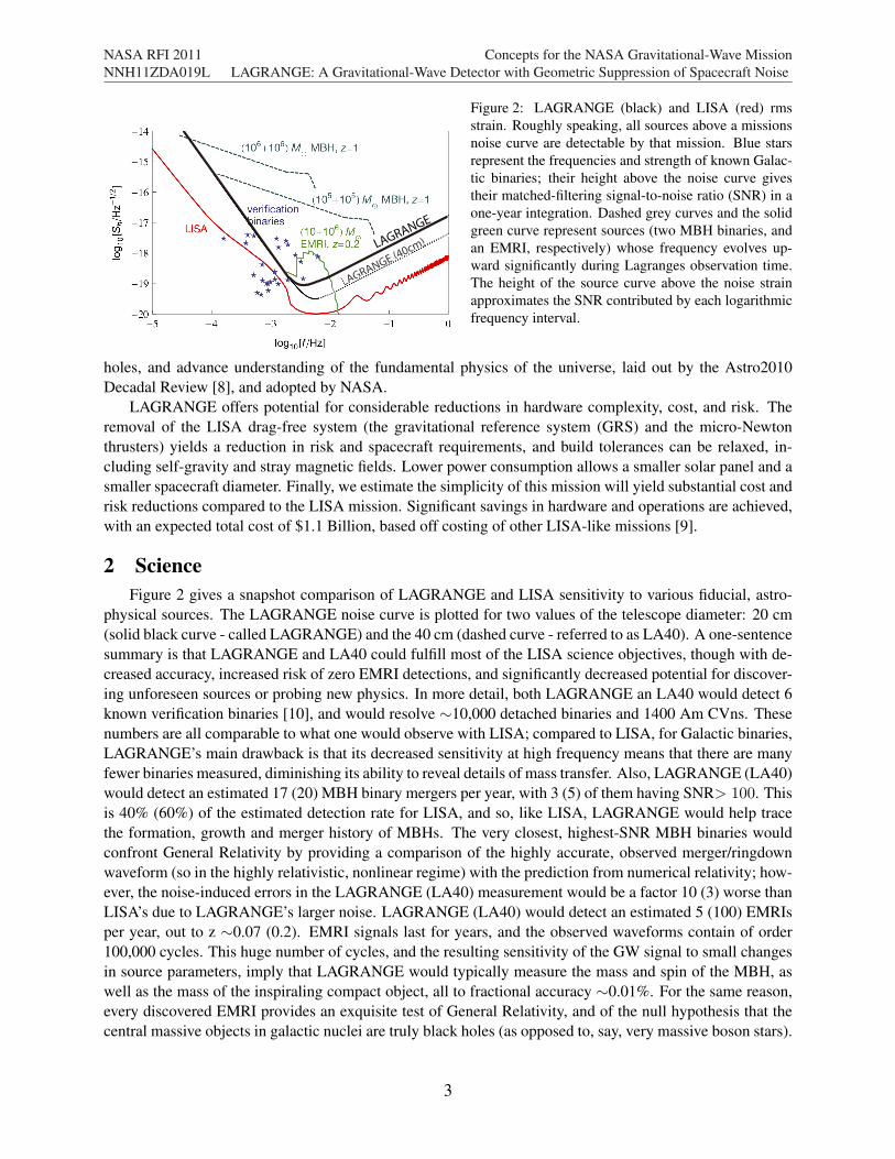
Figure 2: LAGRANGE (black) and LISA (red) rmsstrain. Roughly speaking, all sources above a missionsnoise curve are detectable by that mission. Blue starsrepresent the frequencies and strength of known Galac-tic binaries; their height above the noise curve givestheir matched-filtering signal-to-noise ratio (SNR) in aone-year integration. Dashed grey curves and the solidgreen curve represent sources (two MBH binaries, andan EMRI, respectively) whose frequency evolves up-ward significantly during Lagranges observation time.The height of the source curve above the noise strainapproximates the SNR contributed by each logarithmicfrequency interval.
holes, and advance understanding of the fundamental physics of the universe, laid out by the Astro2010Decadal Review [8], and adopted by NASA.
LAGRANGE offers potential for considerable reductions in hardware complexity, cost, and risk. Theremoval of the LISA drag-free system (the gravitational reference system (GRS) and the micro-Newtonthrusters) yields a reduction in risk and spacecraft requirements, and build tolerances can be relaxed, in-cluding self-gravity and stray magnetic fields. Lower power consumption allows a smaller solar panel and asmaller spacecraft diameter. Finally, we estimate the simplicity of this mission will yield substantial cost andrisk reductions compared to the LISA mission. Significant savings in hardware and operations are achieved,with an expected total cost of $1.1 Billion, based off costing of other LISA-like missions [9].
2 ScienceFigure 2 gives a snapshot comparison of LAGRANGE and LISA sensitivity to various fiducial, astro-
physical sources. The LAGRANGE noise curve is plotted for two values of the telescope diameter: 20 cm(solid black curve - called LAGRANGE) and the 40 cm (dashed curve - referred to as LA40). A one-sentencesummary is that LAGRANGE and LA40 could fulfill most of the LISA science objectives, though with de-creased accuracy, increased risk of zero EMRI detections, and significantly decreased potential for discover-ing unforeseen sources or probing new physics. In more detail, both LAGRANGE an LA40 would detect 6known verification binaries [10], and would resolve "10,000 detached binaries and 1400 Am CVns. Thesenumbers are all comparable to what one would observe with LISA; compared to LISA, for Galactic binaries,LAGRANGE’s main drawback is that its decreased sensitivity at high frequency means that there are manyfewer binaries measured, diminishing its ability to reveal details of mass transfer. Also, LAGRANGE (LA40)would detect an estimated 17 (20) MBH binary mergers per year, with 3 (5) of them having SNR> 100. Thisis 40% (60%) of the estimated detection rate for LISA, and so, like LISA, LAGRANGE would help tracethe formation, growth and merger history of MBHs. The very closest, highest-SNR MBH binaries wouldconfront General Relativity by providing a comparison of the highly accurate, observed merger/ringdownwaveform (so in the highly relativistic, nonlinear regime) with the prediction from numerical relativity; how-ever, the noise-induced errors in the LAGRANGE (LA40) measurement would be a factor 10 (3) worse thanLISA’s due to LAGRANGE’s larger noise. LAGRANGE (LA40) would detect an estimated 5 (100) EMRIsper year, out to z "0.07 (0.2). EMRI signals last for years, and the observed waveforms contain of order100,000 cycles. This huge number of cycles, and the resulting sensitivity of the GW signal to small changesin source parameters, imply that LAGRANGE would typically measure the mass and spin of the MBH, aswell as the mass of the inspiraling compact object, all to fractional accuracy "0.01%. For the same reason,every discovered EMRI provides an exquisite test of General Relativity, and of the null hypothesis that thecentral massive objects in galactic nuclei are truly black holes (as opposed to, say, very massive boson stars).
3
NASA RFI 2011NNH11ZDA019L
Concepts for the NASA Gravitational-Wave MissionLAGRANGE: A Gravitational-Wave Detector with Geometric Suppression of Spacecraft Noise
However our best estimates of the EMRI event rate is still rather poorly constrained by existing data andsimulations, and could certainly be too optimistic by a factor of "100. Therefore for LA40 there is a modestrisk that no EMRIs at all would be observed, and for LAGRANGE that risk is significant.
As mentioned above, descoping from LISA to LAGRANGE has perhaps its greatest effect on the mis-sion’s discovery potential. The principal reason is the decrease from 6 laser links to 4. With only 4 links,only a single Time-Delay Interferometry (TDI) observable can be constructed. With only one observable,a stochastic GW background would be very difficult to distinguish from some unexpected source of instru-mental noise. By comparison, 6-link LISA permits the construction of 3 independent TDI observables, fromwhich one can independently estimate the magnitudes of both the instrumental noise and the GW noise fromthe early universe. Similarly, consider the case of searches for GW bursts; e.g., the case of bursts fromcosmic (super-) strings, which have a characteristic (roughly) sine-Gaussian shape. Detected in only onechannel, it would be difficult to have great confidence that the burst was not some instrumental artifact. Butwith either 5 or 6 links, one could measure both components of polarization, which would provide a powerfulveto against non-GW bursts.
3 Mission DescriptionThe LAGRANGE mission is based heavily on the LISA mission. Summarized in Table 1, it consists of
three widely separated spacecraft in heliocentric orbit with four one-way inter-spacecraft optical links. Eachspacecraft is designed to support the scientific payload that consists of the interferometer measurement sys-tem (IMS) and the spacecraft force measurement (SFM) instruments. The two end spacecraft have one IMSand one set of SFM instruments, while the middle spacecraft has two IMS and one set of SFM instruments.The IMS and the SFM instruments will record data, which will be decimated and sent to Earth periodically.This data will be combined in post-processing.
3.1 Interferometer Measurement SystemLAGRANGE shares many components of the interferometric measurement system with LISA: the phase
measurement chain; laser frequency noise control; ultra stable optical path length. However, stability re-quirements on many of these components can be relaxed by a factor of 16 as shot noise, the dominantinterferometric noise, is approximately 16 times higher than on LISA (a factor of 4 relaxation because ofthe arm length, and a factor of 4 because we choose a smaller telescope diameter, single link displacementnoise of 146 pm/
#Hz for LAGRANGE compared with 8.6 pm/
#Hz for LISA). At the same time, some
demands on the IMS are more stringent than on LISA: the light power will be 250 times less than for LISAand the Doppler shifts (heterodyne frequency) will be up to 6 times larger.
Phase Measurement System: Conceptually, the phase measurement chain – photoreceivers, analog-to-digital converters, and phasemeters – that make up the phase measurement system could remain largelyunchanged from those already developed for LISA. The reduced light power and larger Doppler shifts (het-erodyne frequency) motivate wider bandwidth and higher gain photoreceivers and faster processing electron-ics (by a factor of 4). These additional requirements may be accommodated with minor modifications andthe relaxation of the displacement requirements.
Laser Frequency Control and Ultra-Stable Oscillator Noise Cancellation: Laser frequency controland ultra-stable oscillator noise cancellation will be performed in the same manner as LISA, using laser pre-stabilization via arm locking [11], and Time Delay Interferometry (TDI) [12, 13]. For cost and complexityreductions we have removed on-board laser stabilization in favor of arm locking alone, which has been shownto meet the pre-TDI requirements on LISA [14, 15, 16].
4
NASA RFI 2011NNH11ZDA019L
Concepts for the NASA Gravitational-Wave MissionLAGRANGE: A Gravitational-Wave Detector with Geometric Suppression of Spacecraft Noise
Table 1: LAGRANGE Mission ParametersPredicted Event Rates and Event Numbers
Frequency band 100 µHz to 0.1 HzMassive black hole mergers 15 yr!1 to 25 yr!1, 2-5 with SNR > 100Extreme mass ratio inspirals 10M" + 106 M" pair seen out to z = 0.1Detectable verification binaries 6, (with SNR > 5).Galactic binaries 10000 detached binaries yr!1 and 1400 Am CVns yr!1
MissionScience measurement Michelson interferometer phase change induced by incident gravitational radiationDuration 2 years science operation (4 years including transfer and commissioning)Orbits Three spacecraft: S/C 1 (S/C 3) in 8# Earth leading (trailing) heliocentric orbit, S/C 2 in
orbit around the 2nd Lagrange Point of the Sun-Earth system.Optical Links Dual one-way interferometer links between S/C 1 and 2, and between S/C 2 and 3.Spacecraft bus Provides power, communication. Reaction wheels for attitude control and hydrazine de-
saturation thrusters. Power supply from solar cells.Propulsion module Used for orbit insertion, chemical propulsion. Mass, Power.Constellation Isosceles triangle: Central S/C at 2nd Lagrange point, end S/C at two other vertices. Inter-
nal angle at central S/C is 164#, and arm lengths are 2.1!1010m. At end S/C, interferom-eter link direction is at normal to Sun’s radial direction to receive geometric suppressionof solar forces. Arm lengths ±5%, central S/C angle ±0.1#, rel. S/C velocity < 100 m/s,geometric suppression > 120
Total mass 2820 kg, including LV adapterPower per S/C 450 WSpacecraft Radius 0.9 mData volume 60 Mbit/day per spacecraft (0.3 Hz interferometer data rate).Launch vehicle Falcon 9, Block 3
InstrumentsAttitude Control: < 100 µrad between attitude correction maneuvers.
Reaction Wheels 4 per S/C GRAIL-like reaction wheels (TBC).Desaturation Thrusters 3 clusters per S/C Hydrazine propulsion systemSpacecraft Force Measurement. Single link acceleration : a(f) $ 2.5! 10!16 ! (1Hz/f)3/4 m/s2/
#Hz
Solar Wind Monitor 1 per S/C SWEPAM-like [4]Radiometer 1 per S/C VIRGO-like radiometer [6]Accelerometer 1per S/C GOCE-like [19]Interferometric Measurement System: Single link displacement : x(f) $ 150 pm/
S/C ranging to 1 m, clock noise transferLaser 2 (S/C 1, 3), 4 (S/C 2) 1.2 W, wavelength 1064 nm, frequency stability
(free-running) 30 kHz/#Hz ! (1Hz/f), fractional
power stability 10!4/#Hz
Optical Bench 1 per S/C Fused silica optics bonded to a Zerodur BenchTelescope 1 (S/C 1, 3), 2 (S/C 2) 20 cm diameter. Fixed telescope pointing.In-field guiding mirror 2 (middle S/C only) Michelson internal angle variation ±0.15#
Phase measurement system 1 per S/CPoint ahead mirror No actuation 1 µrad offset (in plane only), ±10 nrad variability.
3.2 Force measurement systemThe SFM departs significantly from LISA’s GRS. Rather than isolating the proof mass (the measurement
fiducial for LISA), this mission uses instruments to measure the parameters that lead to the forces on thespacecraft, and uses this data to subtract the effect of the forces in post-processing. We envisage the SFM
5
NASA RFI 2011NNH11ZDA019L
Concepts for the NASA Gravitational-Wave MissionLAGRANGE: A Gravitational-Wave Detector with Geometric Suppression of Spacecraft Noise
to consist of three instruments: a solar wind monitor, a radiometer, and an accelerometer. Each instrumentwill make measurements in the radial direction: with the solar wind monitor and radiometer measuring pa-rameters related to the solar wind pressure and solar radiation pressure respectively, while the accelerometerwill make a direct measurement of the acceleration of the spacecraft. While three instruments are surplus tocorrect for two forces, the accelerometer can be used as a redundant sensor and can be used to provide anabsolute calibration for the solar pressure forces.
Solar wind monitor: A solar wind monitor on each spacecraft will measure the speed, direction, anddensity of the solar wind at a rate of 0.1 Hz. These data will be transmitted to the ground where the resultingforce on the spacecraft will be calculated. The performance of previously flown solar wind monitors, suchas the SWEPAM instrument, appears to be sufficient to calculate the force of the solar wind applies on thespacecraft to a precision of 1% (see Appendix B).
Radiometer: The solar radiation on each spacecraft will be measured with sufficient precision to enablesubtraction of the resulting spacecraft acceleration noise. The DC component of the solar radiation pressureon the spacecraft is approximately 1000 times the fluctuating component in a 1 Hz bandwidth [17, 18]. Theradiometer flown on the SOHO mission has sufficient noise performance and dynamic range to enable morethan a factor of 100 reduction of radiation pressure fluctuations, enough to reduce radiation pressure wellbelow the LISA acceleration noise budget.
Accelerometer: We propose to use an accelerometer like the ONERA accelerometer [19] used on theGOCE mission in concert with the radiometer and the solar wind monitor. The accelerometer noise perfor-mance is aacc(3 mHz) = 3 ! 10"12 m/s2/
#Hz and it has sufficient dynamic range of 3 ! 106 /
#Hz to
measure the solar fluctuations without drag compensation. The accelerometer could be used to provide aabsolute calibration of acceleration of the radiometer and solar wind monitor and additional diagnostics.
3.3 Spacecraft ImpactThe removal of the LISA drag-free system yields several benefits. The spacecraft build requirements are
lessened: self-gravity and stray magnetic fields are less of a concern. We estimate 340 kg of reduction perspacecraft is possible. Since the drag-free system including thrusters use significant power, spacecraft power(approximately 350 W in total) is reduced, thus decreasing the size of the solar panels and lowering mass.The complexity of the interferometer on the bench is lessened, as no proof mass interferometry is needed.
3.4 Measurement ConceptThe measurement and calibration of noise sources in the interferometer link can be illustrated by con-
sidering only the acceleration noise of the spacecraft due to solar radiation pressure fluctuations and assumethis force noise acts precisely radially from the Sun. If the face of the spacecraft is aligned precisely with theradial direction, the resulting acceleration noise will also be purely radial. We label the acceleration noise ofthe jth spacecraft facing the ith spacecraft aij(t) = #ij(t)aij with #ij(t) the magnitude of the accelerationand aij a unit vector diescribing the direction of the acceleration . The acceleration noise in individual linksare given by sij = (aij(t)%Dij aji(t)) ·nij , where nij is a unit vector describing the direction of propagationof the interferometer link and Dij is the delay operator defined Dija(t) = a(t% Lij/c) [20] . The accelera-tion noise in the interferometer link between S/C 1 and S/C 2 is s12(t) = a12(t)%D21a21(t) sin!!, where!! is the deviation of the angle subtended by the radial direction at S/C 1 and the interferometer link betweenS/C 1 and S/C 2 from 90! (a maximum of 0.6! for the orbits considered here). Thus, the first order couplingof acceleration noise of S/C 1 into this interferometer link is suppressed by a minimum of 100. Next, wepropose to measure the radiation pressure fluctuations in the radial direction using a radiometer. Then thismeasurement will be used to subtract the disturbance from the interferometer measurement channels. Themeasurement of the apparatus on S/C j can be converted to acceleration #mj(t) = #ij(t) + #Nj(t), where#Nj(f) is the underlining noise floor of the measurement apparatus. This measurement is scaled by sin!!
6
NASA RFI 2011NNH11ZDA019L
Concepts for the NASA Gravitational-Wave MissionLAGRANGE: A Gravitational-Wave Detector with Geometric Suppression of Spacecraft Noise
to cancel the S/C acceleration noise from the interferometer channels. The result is a calibrated measurement
showing the residual noise of S/C 1 is limited by the noise floor of the acceleration noise measurementapparatus scaled by sin!!. Thus, the result is a reduction of apparatus noise over using the same apparatusto measure the acceleration in the sensitive direction. This reduction of apparatus noise moves the noiseperformance of existing instruments into the performance required for LISA type sensitivities. Of course,the acceleration noise of S/C 2 remains in equation 1. But the radial component of this noise is commonto both arms of the Michelson interferometer and cancels to a high level when the Michelson combinationis formed, as shown in Appendix A. Note that we do not assume that the acceleration noise is correlatedbetween spacecraft, nor assume any common mode rejection factor.
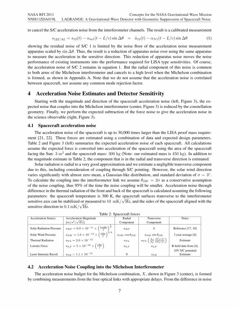
4 Acceleration Noise Estimates and Detector SensitivityStarting with the magnitude and direction of the spacecraft acceleration noise (left, Figure 3), the ex-
pected noise that couples into the Michelson interferometer (center, Figure 3) is reduced by the constellationgeometry. Finally, we perform the expected subtraction of the force noise to give the acceleration noise inthe science observable (right, Figure 3).
4.1 Spacecraft acceleration noiseThe acceleration noise of the spacecraft is up to 30,000 times larger than the LISA proof mass require-
ment [21, 22]. These forces are estimated using a combination of data and expected design parameters.Table 2 and Figure 3 (left) summarize the expected acceleration noise of each spacecraft. All calculationsassume the expected force is converted into acceleration of the spacecraft using the area of the spacecraftfacing the Sun: 3 m2 and the spacecraft mass: 300 kg (Note: our estimated mass is 450 kg). In addition tothe magnitude estimate in Table 2, the component that is in the radial and transverse direction is estimated.
Solar radiation is radial to a very good approximation and we estimate a negligible transverse componentdue to this, including consideration of coupling through S/C pointing. However, the solar wind directionvaries significantly with almost zero mean, a Gaussian-like distribution, and standard deviation of $ = 3!.To calculate the coupling into the interferometer link we assume !SW = 2$ as a conservative assumptionof the noise coupling, thus 95% of the time the noise coupling will be smaller. Acceleration noise throughdifference in the thermal radiation of the front and back of the spacecraft is calculated assuming the followingparameters: the spacecraft temperature is 300 K, the spacecraft surfaces transverse to the interferometersensitive axis can be stabilized or measured to 10 mK/
#Hz, and the sides of the spacecraft aligned with the
10V S/C potentialLaser Intensity Recoil aIR = 1.1$ 10!15 0 aIR Estimate
4.2 Acceleration Noise Coupling into the Michelson InterferometerThe acceleration noise budget for the Michelson combination, X , shown in Figure 3 (center), is formed
by combining measurements from the four optical links with appropriate delays. From the difference in noise
7
NASA RFI 2011NNH11ZDA019L
Concepts for the NASA Gravitational-Wave MissionLAGRANGE: A Gravitational-Wave Detector with Geometric Suppression of Spacecraft Noise
10 4 10 3 10 2 10 1 10010 15
10 14
10 13
10 12
10 11
10 10
Frequency [Hz]
Acce
lera
tion
[m/s
2 /rtH
z]
Acceleration Noise on a single spacecraft
Radiation PressureSolar WindThermal RadiationLaser RecoilLISA Proof Mass
Figure 3: The acceleration noise for (left) a single spacecraft, (center) acceleration noise in the Michelson combination,X , and (right) the final noise in X after force noise subtraction.
levels between the single spacecraft acceleration and in X we see the solar radiation pressure and thermalradiation have significant reduction in couplings because of their large radial component. However, the solarwind pressure has smaller suppression because of its larger non-radial component (due to deviation of thesolar wind from the radial direction). The calculation of the couplings, detailed in Appendix A, is entirelybased on the geometry of the constellation and the direction of each force. The radial spacecraft accelerationnoise from the end spacecraft couples into X with a suppression of factor of 100 compared with accelerationnoise in the sensitive (transverse) direction. The suppression factor of the radial acceleration noise of themiddle spacecraft is common to both interferometer arms and receives a factor of 500 suppression.
4.3 Force calibration and subtractionBy direct measurement of the solar wind and solar radiation, the resulting force on the spacecraft can
be scaled and subtracted from the Michelson data. With current instruments, a factor of 100 of solar windforce and solar radiation pressure force appears to be achievable, though further investigation into solar windcalibration is needed. The calibrated acceleration noise budget shown in Figure 3 (right), is a factor of 20higher than the LISA acceleration noise at 100µHz and reduces at higher frequencies. The final accelerationnoise in the Michelson can be approximated by AX $ 5!10"16!(1Hz/f)3/4 m/s2/
#Hz and the resulting
displacement noise is calculated by XAccel =AX
(2"f)2 m/#Hz.
4.4 Expected Interferometer StrainWith acceleration noise of XAccel in the Michelson combination and interferometer measurement system
noise of XIMS in the Michelson combination, the sensitivity can be calculated as
h(f) =
#5
2
T (f)
sin(2")
!XAccel(f)2 +XIMS(f)2
(2%f)2L(2)
where T (f) is the interferometer response to gravitational waves 1. The interferometer response differs fromLISA in two important ways: the arm length is longer lowering the corner frequency of the interferometerresponse to gravitational waves by a factor of 4, and the angle of the Michelson arms 2" = 164! reduces thesensitivity to gravitational waves for fixed arm length by a factor of 3.
5 Mission Design and AlternativesWe propose a two year mission and use a less expensive launch vehicles, the SpaceX Falcon 9, expected
to be available at launch time. Due to the lack of a drag free system, there are less stringent requirements for
1T (f)!1 $"
1 + (f/(a0f0))2, with f0 = c/(2L) = 7mHz and a0 = 0.41
8
NASA RFI 2011NNH11ZDA019L
Concepts for the NASA Gravitational-Wave MissionLAGRANGE: A Gravitational-Wave Detector with Geometric Suppression of Spacecraft Noise
thrusters than those planned by LISA. We baseline a smaller (20cm diameter telescope) to further reduce thespacecraft size and mass, while the relatively small change of the Michelson vertex angle over the missionlifetime (±0.15!) allows the telescope actuation system required for LISA to be replaced replaced within-field guiding - actuation of the telescope secondary or other optical element smaller than the primary.
5.1 Launch and Orbit InsertionA detailed analysis of the possible spacecraft trajectories has not been completed, however based on
SGO-Mid [9] and missions at L2 we expect the that achieving the required orbits is entirely feasible. Thethree S/C and propulsion modules will be launched on a single launch vehicle. One scenario could be allthree S/C and prop-modules could travel to L2 then, S/C 1 and S/C 3 could be allowed to follow the invariantmanifolds to leave Earth and head for heliocentric orbits. S/C 3 can naturally depart L2 and drift back toposition. S/C 1 could travel from L2 to L1 which costs very little fuel (!V ! 1 m/s) but will take about 6months, then to depart L1 and head for its final location 8! in front of the Earth. Once S/C 1 and S/C 3 reachtheir respective heliocentric locations, they need to perform a maneuver to insert into their final orbits.
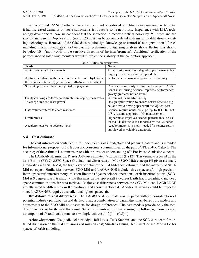
5.2 OrbitsThe orbits are designed to maintain the constellation for as long as possible with minimal station keeping.
The parameters of the constellation plotted in Figure 4 show that reasonable range-rate and range can bemaintained for the nominal 2 year mission. Minor station keeping maneuvers are required 4-6 times peryear to maintain S/C 2 orbit about L2. We have assumed no station keeping for S/C 1 or S/C 3. With theinitial velocities set in this orbit simulation, all mission parameters are upheld for almost 2 years (geometricsuppression drops below 100 after 630 days). With optimization, we expect all orbital mission parametersdescribed in Table 1 could be met for 2 years.
0 100 200 300 400 500 600 7002
2.05
2.1
2.15
2.2 x 10¹⁰
Time [days]
S/C
Sep
arat
ion
[m]
0 100 200 300 400 500 600 700150
100
50
0
50
100
150
Time [days]
Rel
ativ
e S/
C v
eloc
ity [m
/s]
S/C 1 S/C 2S/C 3 S/C 2
S/C 1 S/C 2S/C 3 S/C 2
0 100 200 300 400 500 600 700163.6
163.7
163.8
163.9
164
Time [days]
Mic
hels
on a
ngle
[deg
rees
]
0 100 200 300 400 500 600 70088.5
89
89.5
90
90.5
91
Time [days]
Sun
Lin
k An
gle
[deg
rees
]
Sun S/C 1 S/C 2Sun S/C 3 S/C 2
Figure 4: Left: The S/C separation (top) and relative velocity (bottom). Right: The Michelson internal angle (top)and and the angle of the interferometer link to the Suns radial direction (bottom). Values between dashed lines give ageometric suppression factor of 100, or more.
5.3 Work to goThe LAGRANGE mission presented here is a plausible implementation of the geometric suppression of
spacecraft noise based on our extensive experience with LISA, gravity sensing, and solar sensing. Whileevery attempt has been made to give a reasonable values the time and rigor required for mission designoptimization has not been applied. Specific items that can be explored to optimize the science per dollar andbalance risk against performance are addressed in Table 3.
9
NASA RFI 2011NNH11ZDA019L
Concepts for the NASA Gravitational-Wave MissionLAGRANGE: A Gravitational-Wave Detector with Geometric Suppression of Spacecraft Noise
Although LAGRANGE affords many technical and operational simplifications compared with LISA,it has increased demands on some subsystems introducing some new risks. Experience with LISA tech-nology development leave us confident that the reduction in received optical power by 250 times and thesix-fold increase in Doppler shifts (up to 120 m/s) can be accommodated with minor modification to exist-ing technologies. Removal of the GRS does require tight knowledge or control of non-gravitational forcesincluding thermal re-radiation and outgassing (preliminary outgassing analysis shows fluctuations shouldbe below 10"15m/s2/
#Hz in the sensitive direction of the interferometer). Additional verification of the
performance of solar wind monitors would reinforce the viability of the calibration approach.
Table 3: Mission alternativesTrade Notes4 interferometer links versus 6 Added links may have degraded performance but
might provide better science per dollarAttitude control with reaction wheels and hydrozenethrusters vs. alternate (eg micro- or milli-Newton thruster)
Performance versus mass/power/cost/maturity
Separate prop module vs. integrated prop system Cost and complexity versus performance. Addi-tional mass during science improves performance;gravity gradients not an issue
Freely evolving orbits vs. periodic stationkeeping maneuvers Current orbits are life limitingTelescope size and laser power Design optimization to ensure robust received sig-
nal and avoid driving spacecraft and optical costData volume/rate vs telecom resources Science requirements only go up to 0.1 Hz, but
LISA system supported 1 Hz measurements.Orbiter mass Higher mass improves science performance, so ex-
tra mass is desirable as supported by the LauncherAccelerometer vs no accelerometer Accelerometer not strictly needed for science return
but viewed as valuable diagnostic
5.4 Cost estimateThe cost information contained in this document is of a budgetary and planning nature and is intended
for informational purposes only. It does not constitute a commitment on the part of JPL and/or Caltech. Theaccuracy of the estimate is commensurate with the level of understanding of a Pre-Phase A mission concept.
The LAGRANGE mission, Phases A-F cost estimate is $1.1 Billion (FY12). This estimate is based on the$1.4 Billion (FY12) GSFC Space Gravitational Observatory - Mid (SGO-Mid) concept [9] given the manysimilarities with SGO-Mid, the high level of detail of the SGO-Mid cost estimate, and the maturity of SGO-Mid concepts. Similarities between SGO-Mid and LAGRANGE include: three spacecraft, high precisioninter- spacecraft interferometry, mission lifetime (2 years science operation), orbit insertion points (SGO-Mid is 9 degrees Earth trailing, while this mission has spacecraft 8 degrees Earth leading/trailing), and deepspace communications for data retrieval. Major cost differences between the SGO-Mid and LAGRANGEare attributed to differences in the hardware and shown in Table 4. Additional savings could be expectedsince LAGRANGE requires a smaller and lighter spacecraft.
Breakdown of cost differences: The LAGRANGE estimate was prepared without consideration ofpotential industry participation and derived using a combination of parametric mass-based cost models andadjustments to the SGO-Mid cost estimate for design differences. The cost models provide only the totaldevelopment cost for the first flight unit. Subsequent units are estimated using the following learning curveassumption of N total units: total cost = single unit cost ! 5(1% (0.8)N ).
Acknowlegments: We gladly acknowledge: Jeff Livas, Tuck Stebbins and the SGO core team for de-tailed discussion on the SGO missions and mission cost; Min-Kun Chung, Ted Sweetser and Martin Lo forspacecraft orbit modeling.
10
NASA RFI 2011NNH11ZDA019L
Concepts for the NASA Gravitational-Wave MissionLAGRANGE: A Gravitational-Wave Detector with Geometric Suppression of Spacecraft Noise
6 References and Citations[1] P. Bender and K. Danzmann, and the LISA Study Team, Doc. MPQ 233 (1998).[2] Y. Chen and S. Kawamura, Phys. Rev. Lett. 96, 231102 (2006)[3] W. M. Folkner, A non-drag free graviational wave detector. Private communications 2008; W. M. Folkner, ”A
non-drag-free gravitational wave mission architecture”, Concepts for the NASA Gravitational-Wave Mission,call (NNH11ZDA019L) (2011).
[4] D. J. McComas, S. J. Bame, P. Barker, W. C. Feldman, J. L. Phillips, P. Riley, and J. W. Griffee, Space ScienceReviews, 563 86 (1998); http://faesr.ucar.edu/view/835, http://swepam.lanl.gov/
[5] E. C. Stone, A. M. Frandsen, R. A. Mewaldt, E. R. Christian, D. Margolies, J. F. Ormes, and F. Snow, SpaceScience Reviews, 1, 86 (1998); http://www.srl.caltech.edu/ACE/
[6] T. Appourchaux, B. N. Andersen, C. Frohlich, A. Jimenez, U. Telljohann, and C. Wehrli, Solar Physics 170 27,(1997).
[7] C. Frohlich, J. Romero, H. Roth, et al. Solar Physics, 101 162, (1995).[8] Astro2010: The Astronomy and Astrophysics Decadal Survey http://sites.nationalacademies.
org/bpa/BPA_049810[9] Space Gravitational Observatory - Mid (SGO-Mid) concept. Submitted to concepts for the NASA Gravitational-
Wave Mission, call (NNH11ZDA019L) (2011).[10] Gijs Nelemans, Class. Quantum Grav. 094030 26 (2009).[11] B. S. Sheard, M. B. Gray, D. E. McClelland, and D. A. Shaddock, Phys. Lett. A 320, 9 (2003).[12] J. W. Armstrong, F. B. Estabrook, and M. Tinto, ApJ 527 814 (1999)[13] G. de Vine, B. Ware,K. McKenzie, R E. Spero, W. M. Klipstein, and D. A. Shaddock Phys. Rev. Lett. 104,
211103 (2010).[14] The LISA Frequency Control White Paper, D. A. Shaddock, et al. ESA document LISA-JPL-TN-823, (2009).[15] K. McKenzie, R. E. Spero, and D. A. Shaddock Phys. Rev. D 80 102003 (2009)[16] J. I. Thorpe, P. Maghami, J. Livas, Phys. Rev. D 83122002 (2011)[17] Bonny L. Schumaker, LISA’s Disturbance Reduction System Lecture, Caltech Physics Course 2002.[18] H. Peabody, S. Merkowitz, LISA Thermal Design 5th LISA Symposium (2004)[19] J.-P. Marque, B. Christophe, F. Liorzou, G. Bodoville, B. Foulon, J. Guerard, V. Lebat, Document IAC-08-B1.3.7
http://www.onera.fr/dmph/goce/IAC-08-B1.3.7.pdf[20] S.V.Dhurandhar, K.R.Nayak, and J.-Y.Vinet, Phys. Rev. D 65, 102002 (2002).[21] H-R. Schulte M. Herz, LISA Measurement Performance, LISA EADS Astrium LISA Mission Formulation Tech-
nical Note LISA-ASD-TN-1002 0.7 (2007)[22] D A Shaddock 2008 Class. Quantum Grav. 25 114012 (2008)[23] V.V. Beletskii, Motion of an Artificial Satellite About Its Center of Mass, Mechanics of Space Flight (1966).[24] Spacecraft attitude determination and control, Edited by J. R. Wertz,Astrophysics and Space Science Library,
Dordrecht: Reidel (1978)[25] D. A. Shaddock, M. Tinto, F. B. Estabrook, and J. W. Armstrong, Phys. Rev. D 68, 061303 (2003)
Concepts for the NASA Gravitational-Wave MissionLAGRANGE: A Gravitational-Wave Detector with Geometric Suppression of Spacecraft Noise
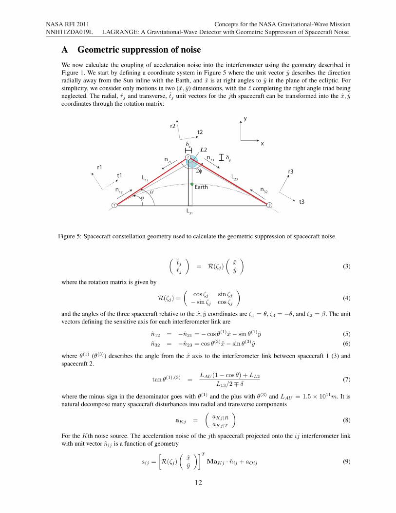
A Geometric suppression of noiseWe now calculate the coupling of acceleration noise into the interferometer using the geometry described inFigure 1. We start by defining a coordinate system in Figure 5 where the unit vector y describes the directionradially away from the Sun inline with the Earth, and x is at right angles to y in the plane of the ecliptic. Forsimplicity, we consider only motions in two (x, y) dimensions, with the z completing the right angle triad beingneglected. The radial, rj and transverse, tj unit vectors for the jth spacecraft can be transformed into the x, ycoordinates through the rotation matrix:
!!’
L31
2"L23L
12
2
31
#y
Earth
L2x
y
r1
t1r3
t3
n12
n21
n32
n23
r2t2
#x
Figure 5: Spacecraft constellation geometry used to calculate the geometric suppression of spacecraft noise.
#tjrj
$= R(&j)
#xy
$(3)
where the rotation matrix is given by
R(&j) =
#cos &j sin &j% sin &j cos &j
$(4)
and the angles of the three spacecraft relative to the x, y coordinates are &1 = !, &3 = %!, and &2 = '. The unitvectors defining the sensitive axis for each interferometer link are
n12 = %n21 = % cos !(1)x% sin !(1)y (5)n32 = %n23 = cos !(3)x% sin !(3)y (6)
where !(1) (!(3)) describes the angle from the x axis to the interferometer link between spacecraft 1 (3) andspacecraft 2.
tan !(1),(3) =LAU (1% cos !) + LL2
L13/2& ((7)
where the minus sign in the denominator goes with !(1) and the plus with !(3) and LAU = 1.5 ! 1011m. It isnatural decompose many spacecraft disturbances into radial and transverse components
aKj =
#aKj|RaKj|T
$(8)
For the Kth noise source. The acceleration noise of the jth spacecraft projected onto the ij interferometer linkwith unit vector nij is a function of geometry
aij =
%R(&j)
#xy
$&TMaKj · nij + aOij (9)
12
NASA RFI 2011NNH11ZDA019L
Concepts for the NASA Gravitational-Wave MissionLAGRANGE: A Gravitational-Wave Detector with Geometric Suppression of Spacecraft Noise
where M is a 2! 2 matrix that describes the coupling of the acceleration noise components aKj into the radialand transverse directions rj , tj . M takes cross coupling into account with off diagonal components )T and )R.
M =
#1 )T)R 1
$. (10)
With )R = 1fT , and T the period of the Earth Orbit about the Sun. )R factors in the transverse-orbital coupling
imposed by fluctuating radial forces, while )T $ 0. The term aOij in Equation 9 describes other interferometernoise sources, such as shot noise, that do not have a geometric interpretation. The Michelson interferometercombination with spacecraft 2 at the vertex can be made up of one way links as X = [s12 +D12s21] % [s32 +D23s23] [25]. If we consider only the acceleration noise in X and approximate the delays of the arms to be equal(Dij = D) we can find the acceleration noise in the Michelson combination
Note that we assume no correlations between the noise on the different spacecraft. The geometric coupling factorsreveal the geometric suppression of radial acceleration noise:
This shows the coupling of transverse spacecraft acceleration into the Michelson combination is twice the trans-verse acceleration noise for the end spacecraft, and four times the transverse spacecraft acceleration for the centerspacecraft. On the other hand, the radial spacecraft acceleration noise coupling into the Michelson combinationis 1/100th that of transverse noise for the end spacecraft and approximately 1/500th for the middle spacecraft.The acceleration noise budget for the Michelson combination, X , is shown in Figure 3 (center). Here, we see thatthe radiation pressure and thermal noise have significant reduction in couplings because their radial component,while the solar wind has a larger transverse component which arises due to deviation of the solar wind from theradial direction.
2For simplicity radial and transverse components of acceleration noise are assumed to be independent. This is notaccurate but doesn’t effect the outcome significantly here.
13
NASA RFI 2011NNH11ZDA019L
Concepts for the NASA Gravitational-Wave MissionLAGRANGE: A Gravitational-Wave Detector with Geometric Suppression of Spacecraft Noise
B Solar wind force and calibration
B.1 Force due to solar wind
The force due to the solar wind is dominated by ions, which can be modeled by an elastic impact withoutreflection [23]. The particle energies are generally completely absorbed, then the particles escape with onlythermal velocity equal to that of the surface molecules [24]. The force delivered by the wind with velocityrelative to the spacercaft, v and direction unit vector v (see Figure 6) is given by
Fsw(f) = %*v2A(N · v)v (21)
where the density is *. To estimate Fsw(f) we used three years of data (2007, 2008, 2009) from the SWEPAM [4]instrument on the Advanced Composition Explorer mission [5]. We estimate the magnitude of the solar windacceleration to be asw(f) = 10!13(1Hz/f)3/4m/s2/
#Hz with a approximately Gaussian distribution in the
direction of the solar wind with a zero mean (about radial) and standard deviation of 3 degrees.
N
S
Radiation Pressure
Direction: RadialTime independentForce direction is tunable with AOI: !
RP
N
V!
SW
Solar Wind Direction: Radial +/- Standard Dev, " = 3 degrees Very time dependent amplitude and directionForce direction is not tunable
!RP
FRP
FSW
Figure 6: Direction of force for radiation pressure and solar wind. N is a unit vector normal to the spacecraft face,S is the unit vector from the spacecraft to the Sun and V is the unit vector of the Solar wind velocity relative to thespacecraft.
B.2 Solar wind measurement precision
The solar wind pressure is P = 12*v
2. The resulting radial and transverse accelerations are respectively
aR =PA cos !SW
m, (22)
aT =PA sin !SW
m, (23)
where A is the area of the of the spacecraft surface that faces the sun, m is the spacecraft mass, and !SW is theangle between the surface normal and the direction to the sun. We approximate cos !SW = 1 and sin !SW =!SW . The acceleration noise spectrum in the (sensitive) transverse direction is
aT =A
m
'P (f)!SW rms + Prms!SW (f)
(= aR(f)!SW rms + arms!SW (f). (24)
where the rms subscript indicates root-mean-square average.
If the direction of the solar wind !SW changes slowly comapred to gravitational-wave signal frequency f , thenaR will be well-correlated with gravitational-wave signal noise arising from the solar wind, and there is no needto explictly measure aT or !SW . That is, the second term in Equation 24 can be neglected, and the residualacceleration noise from the solar wind is given by the measurement noise in the radial acceleration measurementmultiplied by !SW rms. If, on the other hand, the acceleration in the transverse direction is uncorrelated to thenoise in the radial direction, or equivalently the angle is changing rapidly compared to signal frequency f ,then the suppression of the solar wind-induced acceleration is the noise in the angle measurement !SW rms, and
14
NASA RFI 2011NNH11ZDA019L
Concepts for the NASA Gravitational-Wave MissionLAGRANGE: A Gravitational-Wave Detector with Geometric Suppression of Spacecraft Noise
it will be necessary to measure this quantity with high precision. Further study of the properties of the solarwind are needed to know which case applies. If high-precision measurements of !SW are necessary, this can beimplemented with two monitors, one in the radial direction and one in the sensitive direction with approximately10 times higher gain.
15
NASA RFI 2011NNH11ZDA019L
Concepts for the NASA Gravitational-Wave MissionLAGRANGE: A Gravitational-Wave Detector with Geometric Suppression of Spacecraft Noise
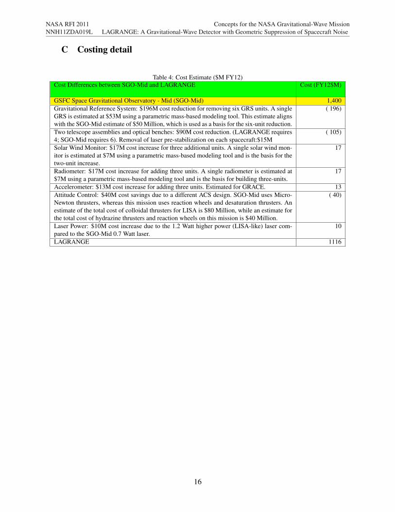
C Costing detail
Table 4: Cost Estimate ($M FY12)Cost Differences between SGO-Mid and LAGRANGE Cost (FY12$M)
GSFC Space Gravitational Observatory - Mid (SGO-Mid) 1,400Gravitational Reference System: $196M cost reduction for removing six GRS units. A singleGRS is estimated at $53M using a parametric mass-based modeling tool. This estimate alignswith the SGO-Mid estimate of $50 Million, which is used as a basis for the six-unit reduction.
( 196)
Two telescope assemblies and optical benches: $90M cost reduction. (LAGRANGE requires4; SGO-Mid requires 6). Removal of laser pre-stabilization on each spacecraft:$15M
( 105)
Solar Wind Monitor: $17M cost increase for three additional units. A single solar wind mon-itor is estimated at $7M using a parametric mass-based modeling tool and is the basis for thetwo-unit increase.
17
Radiometer: $17M cost increase for adding three units. A single radiometer is estimated at$7M using a parametric mass-based modeling tool and is the basis for building three-units.
17
Accelerometer: $13M cost increase for adding three units. Estimated for GRACE. 13Attitude Control: $40M cost savings due to a different ACS design. SGO-Mid uses Micro-Newton thrusters, whereas this mission uses reaction wheels and desaturation thrusters. Anestimate of the total cost of colloidal thrusters for LISA is $80 Million, while an estimate forthe total cost of hydrazine thrusters and reaction wheels on this mission is $40 Million.
( 40)
Laser Power: $10M cost increase due to the 1.2 Watt higher power (LISA-like) laser com-pared to the SGO-Mid 0.7 Watt laser.
10
LAGRANGE 1116
16
NASA RFI 2011NNH11ZDA019L
Concepts for the NASA Gravitational-Wave MissionLAGRANGE: A Gravitational-Wave Detector with Geometric Suppression of Spacecraft Noise