146


LAN SERVER GUIDE
Document Number GG24-3338
March 27, 1989
International Technical Support Center Raleigh Department 985-G, Building 657
P. O. Box 12195 Research Triangle Park, North Carolina

First Edition (March 1989)
This edition applies to the versions of the products listed in the Preface, and to all subsequent releases until otherwise indicated in new editions or Technical Newsletters.
References in this publication to IBM products, programs, or services do not imply that IBM in~ends to make these available in all countries in which IBM operates. Any reference to an IBM program -product in this document is not intended to state or imply that only IBM's program product may be used. Any functionally equivalent program may be used instead.
The information contained in this document has not been submitted to any fo:r:mallBM test and is distributed on an 'As Is' basis without any warranty either express or implied. The use of this information or the implementation of any of these techniques is a customer responsibility and depends on the customer's ability to evaluate and integrate them into the customer's operational environment. While each item may have been reviewed by IBM for accuracy in a specific situation, there is no guarantee that the same or similar results will be obtained elsewhere. Customers attempting to adapt these techniques to their own environments do so at their own risk.
Publications are not stocked at the address given below. Requests for IBM publications should be madeto the IBM branch office serving your locality.
A form for reader's comments is provided at the back of this publication. If the form has been removed, comments may be addressed to IBM Corporation, International Technical Support Center Raleigh, Dept. 985-G, B657, P. O. Box 12195, Research Triangle Park, North Carolina 27709. IBM may use or distribute whatever information you supply in any way it believes appropriate without incurring any obligation to you.
IBM, NetView, NetView/PC~ OS/2, Operating System/2,System/370, AS/400, PS/2, Personal System/2, OS/2 Presentation Manager, Operating System/400, System/36, PROFS, AIX/RT, MVSjXA, VM/XA, PC/AT and System Application Architecture are trademarks of the International Business Machines Corporation.
(c) Copyright International Business Machines Corporation 1989
ii LAN Server Guide

Abstract This document positions the IBM Local area network (LAN) server products. It includes a description of the different LAN servers as well as the host gateways and LAN management options available to the various server environments. The intention is to complement other LAN documents and to provide a single document containing information on IBM's range of LAN server products.
The document is intended for customers, IBM system engineers, and marketing personnel working in the LAN environment who have the responsibility for planning or designing local area networks.
CSYS WS (117 pages)
Abstract iii

iv LA"J Server Guide

Acknowledgements This publication is the result of a residency conducted at the International Technical Support Center in Raleigh.
The author of this document is:
Ben Gosling - ISM Johannesburg, South Africa
Project Advisor:
Guillenno Diaz - ITSC Raleigh, N.C.
Thanks to the following for the invaluable advice and guidance provided in the production of this document:
Guillenno Diaz, ITSC Raleigh, N.C. Joan Cavin, ITSC Raleigh, N.C. Niels Christiansen, ITSC Austin, Tx.
Acknowledgements v

vi LAN Server Guide

Preface
Document Purpose and Scope The purpose of this document is to provide, within a single document, ~ufficient information about the different IBM Loc3.1 Area Network (LAN) server products so that the LAN planner, either the customer or IBM systems engineer, is able to identify the most suitable product or combination of products to meet a specific set of requirements. The document deals with the following server implementations:
• PC LAN Program Version 1.3
• OS/2 LAN Server Version 1.0
• AS/400 PC Support
• PC Support/36
• Enhanced Connectivity Facilities Version 1.1
• NFS under both TCP /IP and AIX
• Financial Branch System Services Version 2.1.1.
In addition the document evaluates the host gateway options available within the different server environments as well as the management capabilities, both in terms of problem determination and administration.
Throughout this document, the term "personal computer" refers to the supported models of IBM Personal Computer and IBM Personal System/2 systems. The term "workstation" is used interchangeably with the term "personal computer".
Audience This document is intended for persons who have the responsibility, at an application level, for deciding on, planning or designing local area networks;
• Customers
• DP management
• Network planning staff
• IBM
• Sales repres~ntatiyes
• Account system engineers
• Network specialist system engineers.
Preface vii
Document Organization The document is organized as follows:
• Chapter I Introduction
Chapter I looks at the concept of LAN servers and provides background information on LAN management.
• Chapter 2 PC LAN Program Version 1.3
Chapter 2 reviews the IBM PC LAN Program V1.3 in terms of its capabilities and host connectivity possibilities.
• Chapter 3 OS/2 LAN Server Version 1.0
Chapter 3 reviews the IBM OS/2 LAN Server Vl.O in terms of its capabilities and host connectivity possibilities.
• Chapter 4 AS/400 PC Support
Chapter 4 reviews the IBM AS/400 PC Support in terms of its capabilities and host connectivity possibilities. It also identifies the differences between AS/400 PCSupport and PC Support/36.
• Chapter 5 Enhanced Connectivity Facilities Version 1.1
Chapter 5 reviews the IBM Enhanced Connectivity Facilities V1.1 in terms of its capabilities and LAN connectivity possibilities.
• Chapter 6 Network File System
Chapter 6 reviews the different IBM Network File System offerings in terms of their capabilities and connectivity possibilities.
• Chapter 7 Financial Branch System Services Version 2.1.1
Chapter 7 reviews the IBM Financial Branch System Services V2.1.1 in terms of its capabilities and connectivity possibilities.
• Chapter 8 Coexistence
Chapter 8 presents a number of coexistence scenarios.
• Chapter 9 Design Considerations
Chapter 9 reviews some of the factors that are significant in terms of server implementations.
viii LAN Server Guide

Related Publications • IBM PC Local Area Network Program Version 1.3 - Getting Started: Installation and
Configuration
• IBM PC Local Area Network Program Version 1.3 - Application Programmers Guide
• IBM PC Local Area Network Program Version 1.3 - Base Services Network Commands - Quick Reference
• IBM PC Local Area Network Program "Version 1.3 - Online Reference
• IBM PC Local Area Network Program Version 1.3 - Online Overview
• IBM PC Local Area Network .Program Version 1.3 - Software Compatibility Reference
• IBM Operating System/2 Local Area Network Server Version 1.0 - Getting Started: Planning and Installation - Release 1 (75X0838)
• IBM Operating System/2 Local Area Network Server Version 1.0·· User's Quick Ref erence - Release 1 (75X0837)
• IBM Operating System/2 Local Area Network Server Version 1.0 - User's Reference -Release 1 (84XOI57)
• IBM Operating System/2 Local Area Network Server Version 1.0 - Network Administrator's Quick Reference - Release 1 (84XOI47)
• IBM Operating System/2 Local Area Network Server Version 1.0 - Network Adminis-trator's Reference - Release 1 (75X0968)
• AS/400 PC Support: Installation Guide (SC21-8 fl8Q)
• AS/400 PC Support: Operations Reference (SC21-8090)
• AS/400 PC Support: Technical Reference (SC21-8091)
• AS/400 PC Support: User's Guide (SC21-8092)
• AS/400 PC Support: Messages and Problem Analysis Guide (SC21-8093)
• AS/400 Communications: User's Guide (SC21-9601)
• Introduction to IBM System/370 to IBM Personal Computer Enhanced Connectivity Facilities (GC23-0957)
• IBM Enhanced Connectivity Facilities - TSO/ E Servers and CMS Servers - Installation Planning and Programmer's Guide (SH20-9677)
• IBM Enhanced Connectivity Facilities - Getting Started with the PC Requesters (SH20-9790)
• IBM Enhanced Connectivity Facilities - PC Requesters Reference (SH20-9678)
• IBM Enhanced Connectivity Facilities - PC Requesters Quick Reference Summary (SH20-9679)
• AIX/370 Network File System: System User's Guide (SC23-2089)
• IBM RT PC }vf anaging the AIX Operating System (SC23-0793)
• IB]\{ TCP/IP for VM: Network File System and Remote Procedure Call }vfanual (SC09-1274)
• IB1'W TCP/IP for Vl'vf: Installation and Maintenence Afanual (GC09-1203)
• IB1'W TCP/IP for VM: Command Reference l'Wanual (GC09-1204)
Preface ix

• IBM TCP/IP for VM: Programmer's Manual (GC09-1206)
• IBM Financial Branch System Services Version 2.1 - Programmer's Reference Manual (GA19-5450)
x LAN Server Guide
ITSC Publication Structure - LANs The rapid evolution of local area network products has resulted in the availability of a wide variety of documents, including the reference materials available with each product and additional technical planning and support material available from various development and support groups.
To assist users to locate appropriate, up-to-date information the International Technical Support Center is structuring its local area network documentation into a library of publications.
Each publication is produced to address some technical requirements of a specific audience as described in the abstract and preface of the document. Because the ITSC publications are intended_ to complement, but not replace reference material available with the products themselves, each document also provides a bibli-0graphy of related publications.
The International Technical Support Center publications related to local area networks have been planned with the following structure in mind to simplify the problem of locating up-to-date infonnation:
1. Overview manuals which provide tutorial information and cross-product conceptual and planning information.
2. Installation manuals which complement product reference material by describing the experiences of the ITSC in installing particular products within a total system. These documents do not address all installation parameters or options as do the product reference materials, but are intended to highlight those aspects of installation which have the greatest impact on successful use of the product, including the relationship between a specific product and other network or system products.
3. Network design and management manuals which describe trade-offs and considerations for managing or planning local area networks.
Preface xi

The current library contains the following publications:
GENERAL CONCEPTS
0024-3178-1 GG24-3338
LAN Concepts LAN and Server
Products Guide
PRODUCT PLANNING AND INSTALLATION
GG24-3291 Installation Guidelines for TokenRing Network Products
GG24-3227 9370 LAN Vol. 2 IEEE 802.3 Support
GG24-311o-1 3725 NTRI Planning and Implementation
GG24-3207 S/36 Token-Ring AttachmentIHS Environ.
NETHORK DESIGN AND MANAGEMENT
GG24-3128 IBM LAN Manager and NetView/PC for Token-Ring Network
xii LAN Server Guide
0024-3164-1 Subsystem Control Unit Installation Guide
GG24-3240 9370 LAN Vol. 1 Token-Ring Support
Table of Contents 1.0 Introduction .................................................. 1 1.1 Overview .....................,............................... 1 1.2 Server Operation ............................................... 1 1.3 LAN Components ............................................. 2 1.4 Server Implementation .......................................... 4 1.5 Server Capacity ................................................ 5 l.6 Workload Considerations ........................................ 6 1.7 Sizing the Server ............................................... 6 1.8 Management .................................................. 7
1.8.1 LAN Management .. ~ . . . . . . . . . . . . . . . . . . . . . . . . . . . . . . . . . . . . . .. 8 1.8.2 LAN Administration ......................................... 10
2.0 PC LAN Program Vl.3 .......................................... 11 2.1 Overview .................................................... 11 2.2 Basic Functions ............................................... 11
2.2.1 Base Services .............................................. 11 2.2.2 Extended Services ........................................... 12
2.2.2.1 User and System Administrator .... '. . ...................... 13 2.2.2.2 Domain ............................................... 13 2.2.2.3 File Sets ............................................... 14 2.2.2.4 Remote Initial Program Load (RIPL) Workstations ............... 14 2.2.2.5 Program Server .......................................... 14 2.2.2.6 Application Selector ...................................... 14
2.3 Operating Environment .......................................... 15 2.3.1 PrerequIsite Hardware ........................................ 15 2.3.2 Prerequisite Software ........... ~ ..... , ....................... 16
2.4 Connectivity ................................ '.................. 16 2.4.1 LAN Connectivity .......................................... 16
2.4.1.1 Typical LAN Configurations ................................ 17 2.4.2 System/370 Host Connectivity .................................. 17
2.4.2.1 Typical IBM PC 3270 Emulation Program V3 Configurations ........ 19 2.4.2.2 A Typical IBM 3270 Workstation Program V1.1 Configuration ....... 24
2.5 Compatibility and Co-existence .................................... 24 2.6 Interfaces .................................................... 25
2.6.1 End-User Interface .......................... . .............. 25 2.6.2 National Language Support .................................... 25
2.7 Security Considerations .......................................... 26 2.8 Performance Considerations ....................................... 26 2.9 Management ... ' ................................ " .............. 26
3.0 OS/2 LAN Server Vl.0 .......................................... 27 3.1 Overview .................................................... 27 3.2 Basic Functions ............................................... 27
3.2.1 Resource Sharing ........................................... 27 3.2.2 Printer Management ......................................... 28 3.2.3 Remote Initial Program Load ................................... 28 3.2.4 Remote Program Execution .................................... 28 3.2.5 Administration and Control .................................... 29
3.3 Operating Environment .......................................... 29
Table of Contents xiii
3.3.1 Prerequisite Hardware ........................................ 29 3.3.2 Prerequisite Software ......................................... 30
3.4 Connectivity ................................... _ ............... 30 3.4.1 LAN Connectivity .................... , ..................... 30
3.4.1.1 A Typical LAN Configuration ............................... 32 3.4.2 Host Connectivity ........................................... 32
3.4.2.1 Typical Configurations Using 3270 Tenninal Emulation ............ 34 3.4.2.2 Typical Configurations Using the APPC Support ................. 37 3.4.2.3 A Typical Configurations Using Asynchronous Terminal Emulation ... 39
3.5 Compatibility and Co-existence .................................... 39 3.6 Interlaces ............. , ............................. , ........ 39
3.6.1 End-User Interlace .......................................... 39 3.6.2 National Language Support .................................... 40
3.7 Security Services ............................................... 40 3.8 Perlormance Considerations ....................................... 41 3.9 Management ........................ , ......................... 41
4.0 AS/400 PC Support ............................................ 43 4.1 Overview .......................... , ........... -.............. 43 4.2 Basic Functions ............................................... 43
4.2.1 Run DOS Commands ........................................ 44 4.2.2 Message Function ........................................... 44 4.2.3 Shared Folders ............................................. 44 4.2.4 Virtual Print ... , ..................................... ; ..... 44 4.2.5 Data Transfer .............................................. 45 4.2.6 Workstation Function ........................................ 45 4.2.7 Organizer ................................................. 45
4.3 Operating Environment .......................................... 46 4.3.1 Prerequisite Hardware ........................................ 46 4.3.2 Prerequisite Software ......................................... 46
4.4 Connectivity ...... -.. -.......................................... 47 4.4.1 LAN Connectivity .......................................... 47
4.4.1.1 A Typical LAN Configuration .................. ; ............ 47 4.4.2 Host Connectivity ........................................... 48
4.4.2.1 A Typical Configuration in an APPN Environment ............... 49 4.4.2.2 Typical Configurations Using 3270 Device Emulation .............. 50
4.5 Compatibility and Coexistence ..................................... 51 4.6 Interlaces .................................................... 52
4.6.1 End User Interlace .......................................... 52 4.6.2 Programming Interfaces ....................................... 52
4.7 National Language Support ....................................... 52 4.8 Security ......... _ ....... _ ....... -.............................. 53 4.9 Perlormance Considerations ................................. ~ ..... 53 4.10 Management ........... -... ; ................ -.................. 54 4.11 PC Support/36 ............................................... 55
4.11.1 Functional Capabilities ...................................... 55 4.11.2 Number of Users Supported .................................. 55 4.11.3 Operating Environment ...................................... 55
4.11.3.1 Hardware Requirements ................ " .......... , ....... 55 4.11.3.2 Software Requirements ........... , ....................... 56
4.11.4 Implementation ............................................ 56
5.0 Enhanced Connectivity Facilities Vl.l ............................... 57 5.1 Overview .................................................... 57 5.2 Basic Functions .................... -........................... 57
5.2.1 Data Base Services .......................................... 58 5.2.2 Virtual Disk ... ,. -.......................................... 58 5.2.3 Virtual File -................................................ 58 5.2.4 Virtual Print ........... -.................................... 58 5.2.5 File Transfer ............................................... 58 5.2.6 Run Host Commands ....................... -................. 59
xiv LAN Server Guide

5.2.7 Routers .................................................. 59 5.3 Operating Environment .......................................... 59
5.3.1 Prerequisite Hardware ........................................ 59 5.3.2 Prerequisite Software ......................................... 60
5.4 Connectivity .................................................. 61 504.1 Connectivity for LAN -Attached Workstations ...................... 61
504.1.1 A Typical Configuration Using IBM PC 3270 Emulation Program V3 as a Gateway ................................................... 62
504.1.2 Typical Configurations Using either a 3174 or a 37xx as a Gateway .... 63 504.1.3 A Typical Configuration Using the 9370's Integrated Token-Ring Support as a Gateway ................................................. 65
5.5 Compatibility and Co-existence .................................... 65 5.6 Interfaces .................................................... 65
5.6.1 End-User Interfaces .......................................... 66 5.6.2 Programming Interfaces ....................................... 66 5.6.3 National Language Support .................................... 66
5.7 Security ..................................................... 67 5.8 Performance Considerations ....................................... 67 5.9 Management ............ ~ ..................................... 67
6.0 Network File System ............................................ 69 6.1 Overview .................................................... 69 6.2 Basic Functions ............................................... 69
6.2.1 Transparent Access to Remote Files .............................. 70 6.2.2 Yellow Pages .............................................. 70 6.2.3 Machine Type Independence ................................... 70
6.2.3.1 Remote Procedure Call .................................... 70 6.2.3.2 External Data Representation ............................... 71
6.204 Transmission Control Protocol/Internet Protocol .................... 71 6.3 Operating Environment .......................................... 72
6.3.1 Prerequisite Hardware ........................................ 72 6.3.2 Prerequisite Software ......................................... 72
6.4 Connectivity .................................................. 73 604.1 TCP /IP Connectivity ........................................ 73
6.4.1.1 Typical TCP/IP Configurations .............................. 75 6.4.2 SNA Network Link .......................................... 76
604.2.1 A Typical SNA Network Link Configuration .................... 77 604.3 System/370 Host Connectivity ........................... ~ ...... 77
6.4.3.1 A Typical 3270 Configuration ............................... 78 6.5 Functional Equivalence .......................................... 78 6.6 Security ..................................................... 79 6.7 Performance Considerations ....................................... 79
7.0 Financial Branch System Services V2.1.1 ............................. 81 7.1 . Overview . ~ .................................................. 81 7.2 Basic Functions .......................................... ' ..... 81
7.2.1 Shared File Server ........................................... 82 7.2.2 Shared DOS Directory Support ................................. 82 7.2.3 Financial I/O Servers ......................................... 83 7.204 Communication Servers ....................................... 83 7.2.5 Operator Interface, 3270 Emulators and Trace Facilities ............... 83 7.2.6 Customization Utility ................... " . . . . . . . . . . . . . . . . . . . . 84 7.2.7 Remote Change Management Services ............................ 84
7.3 Operating Environment ......•................................... 84 7.3.1 Prerequisite Hardware ........................................ 85 7.3.2 Prerequisite Software ......................................... 85
7.4 Connectivity .................................................. 85 704.1 LAN Connectivity .......................................... 86
704.1.1 Typical LAN Configurations ................................ 87 704.2 Host Connectivity ........................................... 87
704.2.1 Typical Host Connectivity Configurations ...................... 89
Table of Contents xv

7.5 Financial Branch System Integrator ................................. 91 7.6 Management ................................................... 92
8.0 Coexistence .................................................. 93 8.1 Background ................................................... 93 8.2 Scenarios ..................................................... 94
8.2.1 Scenario # I ................................................ 94 8.2.2 Scenario #2 ................................................ 95 8.2.3 Scenario #3 ................................................ 96 8.2.4 Scenario #4 ................................................. 97 8.2.5 Scenario #5 ................................................ 98 8.2.6 Scenario #6 ................................................ 99
9.0 Design Considerations .......................................... 101 9.1 General Aspects of LAN Design .................................. 101 9.2 Particular Aspects of Designing the Server-Requester Relationship in a LAN Environment ..................................................... 101
9.2.1 Gateway Selection .......................................... 102 9.2.2 Bridges .................................................. 104 9.2.3 Location of Servers ................. " ...................... ' .. 106 9.2.4 Analysis of the Current Environment and Customer Skills ............. 107
9.3 Performance Factors ........................................... 108 9.3.1 Overhead of Crossing Several Segments .......................... 108 9.3.2 Overhead Created by Heavily Utilized Paths ....................... 109 9.3.3 Performance Degradation of a Low Performing Component ........... 110 9.3.4 Performance Impact for using 4 Mbps or 16 Mbps .................. 111
9.4 Interoperability and the Future with SAA ............................ 112
Acronyms and Abbreviations ......................................... 115
Index .......................................................... 117
XVI LAN Server Guide

List of Illustrations Figure 1. Server-Requester Operation .................................. 2 Figure 2. Bus Topology ............................................ 3 Figure 3. Ring Topology ........................................... 3 Figure 4. Open Network Management Architecture ........................ 8 Figure 5. PC LAN Program V 1.3 Base Services ........................... 17 Figure 6. PC LAN Program V 1.3 Extended Services ....................... 17 Figure 7. 3270 Host Access Using IBM PC 3270 Emulation Program V3 Configured
as a Gateway ............................................ 19 Figure 8. Local or Remote 3270 Host Access via an IBM PC 3270 Emulation Pro-
gram V3 Gateway Station Attached to a 3x74 DFT port ............ 20 Figure' 9. Remote 3270 Host Access Using a 3174 or a 37xx as a Gateway ....... 21 Figure 10. Local 3270 Host Access Using a 3174 or 37xx for Gateway Services ..... 22 Figure 11. Local 3270 Host Access Using the Integrated TRNSC of the 9370 as a
Gateway ............................................... 23 Figure 12. Remote 3270 Host Access Using a 3174 or a 37xx as a Gateway ....... 24 Figure 13. An IBM OS/2 LAN Server V1.0 Environment .................... 32 Figure 14. 3270 Host Access Using a Remote 3174 or 37xx as a Gateway ......... 34 Figure 15. 3270 Host Access Using a Local 3174 or 37xx as a a Gateway ......... 35 Figure 16. 3270 Host Access Using the 9370's Integrated Gateway Support ........ 36 Figure 17. Program-to-Program Communication Using a 37xx as a Gateway ...... 37 Figure 18. APPC Using a Router as a Gateway ............................ 38 Figure 19. ASCII Host Access Using the LAN Servers serial ports .............. 39 Figure 20. ASj400 PC Support ........................................ 48 Figure 21. ASj400 PC Support Connectivity in an APPN Network ............. 49 Figure 22. ASj400 3270 Device Emulation ........ ~ ...................... 50 Figure 23. ASj400 3270 Device Emulation .......... ~ .................... 51 Figure 24. ECF Using IBM PC 3270 Emulation Program V3 Configured as a Gateway 62 Figure 25. ECF Using Either a Remote 3174 or a Remote 37xx as a Gateway ..... 63 Figure 26. ECF ............... ; ................................... 64 Figure 27. ECF Using the 9370's Integrated TRNSC as a Gateway ............. 65 Figure 28. Logical Representation of an NFS LAN ......................... 75 Figure 29. Logical Representation of an NFS LAN Connected to an NFS WAN ... 76 Figure 30. LAN Interconnection over an SNA Link .......... ; ............. 77 Figure 31. 3270 Access from an NFS Host ............................... 78 Figure 3'2. A Small FBSS LAN with 4700 Printer and Shared File Support ........ 87 Figure 33. Two FBSS LANs Sharing Resources over an X.25 Connection ........ 87 Figure 34. FBSS SNA Server Providing Gateway Support .................... 89 Figure 35. FBSS Native X.25 Gateway Support ........................... 90 Figure 36. FBSS 3270 Emulation Gateway Support ......................... 91 Figure 37. PC LAN Program VI) and ASj400 PC Support Coexistence ......... 94 Figure 38. PC LAN Program V1.3 and ASj400 PC Support Coexistence ......... 95 Figure 39. PC LAN Program VI.3 and ECF Coexistence .................... 96 Figure 40. OS/2 Requester and ECF Coexistence ....•..................... 97 Figure 41. ECF and NFS Coexistence .................................. 98 Figure 42. Coexistence of all IBM Server Implementations .................... 99 Figure 43. A bridged LAN Showing Alternate Session Paths ................. 105 Figure 44. Bridging of Remote LANs Using Split Bridges ................... 106 Figure 45. Simplified Queuing Formula for a Single Server ................... 109 Figure 46. A possible Solution for Reducing Remote 3174 Polling Overhead 11 0
List of Illustrations xvii

Figure 47. Remote Bridge .......................................... 111 Figure 48. 16 Mbps Backbone Token-Ring Network ....................... 112 Figure 49. SAA .. ; ............................................... 113
xviii LAN Server Guide
1.0 Introduction
1.1 Overview Local area networks (LANs) provide a connectivity option for users within one or more buildings on a single campus. This capability can be used as an alternative to clustering -users who have a requirement for accessing host resources. Local area networks can support both traditional host connections (such as 3270 devices) via gateways and peer-to-peer connections (such as LAN servers and requesters) using intelligent workstations. IBMl supplies a number of different products to meet user requirements in this environment. The choice of product will generally be influenced by factors such as:
• Equipment already installed
• User's application requirements
• Whether an application is available "off the shelf' for one environment and not another
• Location of data and ability to distribute it
• Number of users requiring access to the data
• Facilities for host access
• Performance requirements
• Volume of data involved, both from a storage and a tr~sfer point of view
• Need for security
• Ability to administer and manage the environment
• Whether other applications such as office applications are available and required.
This bulletin reviews the different products with regard to the services they provide on the LAN and their communications capabilities, and presents the information in a single document. The criteria against which the· products are reviewed are those criteria that are generally rather than specifically applicable to any particular installation. The information is presented in an attempt to simplify the LAN planner's task of selection.
1.2 Server Operation The ability to concentrate resources within a single or possibly multiple processors and then make them available to users of other processors, usually personal computers, is based on the implementation of servers and requesters. These servers and requesters may go by other names, such as servers and users or servers and clients, but generally speaking they perform similar functions. Requesters request services while servers respond to those requests.
1 IBM is a registered trademark of the International Business Machines Corporation.
Introduction

The following example is based on an implementation using the Server-Requester Programming Interface (SRPI) and can be followed in Figure 1 on page 2. Although the SRPI is a specific implementation, the example is useful in explaining the general principles that are employed in this type of environment.
Service requests originating in a requester are passed by a router function, through the SRPI to the communications programs and then via a communications facility to the communications programs in a server host. There the router passes the request via the SRPI to the appropriate server in the server host. The server replies to the service request and the response is transmitted along the reverse path back to the requester. The application program originating the request is unaware of the communication that has taken place and believes that the request was satisfied locally.
Examples of communications programs in the requester and the server host are IBM PC 3270 Emulation Program V3 and ACF /VT AM respectively.
Personal Computer Host Requester server
!. i ! i Router and Router and server-requester server-requester programming interface programming interface
! i ! i Communication < Communication programs programs
>
Figure 1. Server-Requester Operation
1.3 LAN Components
LANs conform to a number of different topologies. Those that are discussed in this document conform to either a bus topology (see Figure 2 on page 3) or a ring topology (see Figure 3 on page 3). These figures show logical representations which in reality may look completely different. The LANs discussed in this document include:
• IBM PC Network Baseband, a bus topology with a media speed of 2 Mbps
• IBM PC Network (Broadband), a bus topology with a media speed of 2 Mbps
• Ethernet2 (IEEE 802.3), a bus topology with a media speed of 10 Mbps
• IBM Token-Ring Network, a physical star/logical ring topology with a media speed of either 4 or 16 Mbps.
The first three LAN s employ a bus topology and use Carrier Sense Multiple Access with Collision Detection (CSMA/CD) as a media access protocol while the IB:\1 Token-Ring
2 LA~ Server Guide
,.

Network is based on a physical star/logical ring topology and uses token passing as its access protocol.
To remote host 1------/ >
E]=Modem
Figure 2. Bus Topology: Logical view showing workstations, a server and a gateway.
To remote host Horkstation Gateway M / >
E] = Modem
Figure 3. Ring Topology: Logical view showing workstations, a server and a gateway.
The components required for the different LANs are listed below. They do not represent the only possibilities and are only provided in order to give the reader an idea of the components required for the different networks discussed in this document.
• The following is required for an IBM PC Network Baseband:
• PC Network Baseband adapter card which slots into each workstation • PC Network Baseband Extender for extending the attachment capability from 8
to 80 workstations • Cabling and accessories • One terminator plug and one wrap plug per LAN.
2 Ethernet is a trademark of the Xerox Corporation.
Introduction 3

• The following is required for an IBM PC Network (Broadband):
• PC Network adapter card which slots into each workstation • One IBM Translator Unit and Splitter - provides radio frequency signals for
transmitting and receiving data • One IBM Base Expander for every eight workstations (max 72 workstations per
network) • Cabling kits (additional splitters allow workstations to be up to 305 meters from
the translator unit).
• The following is required for an Ethernet (IEEE 802.3) Network:
• IEEE 802.3 adapter card which slots into the workstation • 50 ohm coax bus • Fly lead (connects to the adapter card at one end and to the transceiver at the
. other) • Transceiver per adapter card (in some cases it may be included on the adapter
card) • Vampire taps • Two terminator plugs, one for each end of the bus.
• The following is required for an IBM Token-Ring Network:
• Multistation Access Unit (MSAU) • Token-ring network adapter card which slots into the workstation • Fly lead (connects to the adapter card at one end and to the cabling system or
MSA U at the other end) • Cabling for extending the distances between the workstation and MSA U and for
connecting multiple MSAUs.
1.4 Server Implementation Servers share their resources on the network while requesters redirect application service requests for resource input/output (I/O) over the network to one of these servers. Responses, returned to the requester, are passed back to the application as though the service requests had been satisfied locally.
Typically servers are implemented either on a personal computer or in a host. In many instances the host can directly attach to the LAN and the user benefits from the performance of the LAN and the additional processing capabilities that the host has to offer. Where the host does not attach directly to the LAN, either because it cannot do so or because it is located elsewhere, a gateway and possibly a wide area network must be crossed in order for the requester to communicate with the server. The performance of the gateway and the facility connecting the gateway to the host may affect the type of applications that can be run satisfactorily.
Implementations attempt to address, among others, performance and ease-of-use factors. In general, ease-of-use carries an overhead in terms of the number of operations that a processor, either the server or th.e requester, must perform. This translates into cycles used and has an impact on performance.
The volume of data to be tnmsferred and the size of the data record (frame) being sent across the LAN can affect server and network performance. The impact on the server can be viewed in terms of the pathlength overhead on a "per byte" basis. Smaller transfer sizes incur a greater overhead relative to bigger transfer sizes and hence the CPU time for smaller frames is a larger percentage of the total transfer time than it is for bigger transfer sizes.
For some applications the user may wish to transfer portions of a flie from the server to their own machines. Implementations that support a query facility can significantly improve network performance by reducing the amount of data that needs to be transferred.
4 LAN Server Guide

Queries are sent to the server and only the extracted data, and not the entire flie, is returned to the requester.
Implementations that support an intelligent query facility are able to return the extracted data in a specified format. This obviates the need for data manipulation at the requester but increases the workload on the server. This may be significant where the server function resides in a personal computer but is not necessarily so where the server function resides in a host. Benefits to the end user in terms of ease of use may outweigh the cost of the overhead.
Protocol overhead associated with the communication between server and requester may also have an impact on performance. Implementations based on a datagram type service will generally have less communications overhead than implementations based on a connection-oriented service. Users should be aware, however, that a datagram environment is typically less secure than a connection-oriented environment and in times of recovery the delays experienced in the former can be significant due to the fact that recovery must be performed by the end nodes. SNA is typically a connection-oriented protocol while the User Datagram Protocol (UDP) of TCP/IP is as the name implies a datagram service.
1.5 Server Capacity A frequently asked question when evaluating a LAN server is, "How many users can a server support?" A number of factors influence the answer to this question. These include:
• Workload, as discussed in "Workload Considerations" on page 6.
• Request types. Are they program loads as for spreadsheeting, or flie reads as would be the case for a flie transfer, or possibly ftle writes such as record updates or document saves?
• Operating system factors such as flie organization (sequential, index sequential or direct), flie and record sizes, and data base design.
• Processor factors such as internal cycle time, channel speeds and disk seek time.
• Whether or not the processor is dedicated to a specific function.
• The type of LAN being used.
Applications which use flies that are not shared by multiple user workstations, can reduce the server's processing load by downloading the ftle for local processing. This allows the server to do other work.
For random flie access, the size of the flie can also affect the server's capacity. Small flies can become cache-resident in those servers that implement caching. This makes for fast access and can increase the number of liDs that the server can perform. Fileaccesses which open and close the flie for each record read will tend to reduce the server's capacity.
Applications that process data sequentially tend to give better throughput than those that perform random processing. Random processing requires the server to send a single record at a time to the requester which results in the greatest overhead and the lowest throughput.
As more users access a server and the number of requests increases, a point is reached at which the amount of actual; productive work performed decreases. This is due to queuing delays and the unproductive overhead of managing liDs incurred at the server.
The important factor to consider when comparing different LAN s is not the media speed but rather the data throughput capability. The IBM Token-Ring Network, unlike its CSMA/CD counterparts, displays excellent performance characteristics under load. A characteristic of the Token-Ring implementation is that data throughput is close to media speed, and thus by increasing the media speed to 16 Mbps one can expect a proportionate increase in data throughput. Delays on the LAN can translate into delays at the server and
Introduction 5

even if they don't, they will lengthen user response time and may lead to the erroneous conclusion that the server is overloaded.
1.6 Workload Considerations The number of user workstations ona LAN is per se, a meaningless measure of server capacity. Theoretically there can be an infmite number of user workstations for only one server, providing that none of the users power on their workstations. It is thus necessary to assess users in terms of the functions that they perform on the LAN and their working habits.
We can start by categorizing users according to their job descriptions. For example, some users, such as clerical workers, may spend most of their day performing data capture type operations at their workstations. They frequently transfer fues and interact with the server. Others, such as secretarial staff, may only spend half their day at their workstations performing word processing and document transfer type functions. Professionals will typically spend a large portion of their day at their workstations performing analytical type functions that may have very little dependence on the server. Managerial staff on the other hand will only spend a small percentage of their day at their workstations performing functions such as spreadsheet updates. So, usage type is a very important factor .and it goes without saying that the office clerk will use more server capacity than the manager. "Think time" also plays an important role here. The relative percentage. of think time to key time is generally greater for managers and professionals than it is for secretarial staff, who in tum have a relatively higher percentage than do office clerks.
When reviewing the amount of work done by a user at a workstation, it is important to bear in mind that for a given amount of user effort, certain functions will use more server resources than others. Creative functions, such as spreadsheeting or word processing, require data to be transferred to the workstation for local processing and then returned to the server when processing is complete. These functions place a relatively light load on the server. Interactive functions which include inquiries, editing and data entry, generate relatively more fue I/Os than creative functions and hence use more of the server's resources. The heaviest users of server resources are the batch functions. Batch functions typically perform activities such as fue searches, sorts and report generation.
1.7 Sizing the Server Capacity planning theory states that one should allow for peak loads and application growth. The real issue, though, is how to estimate the base requirement in order to leave sufficient capacity for peak loads and the future. This is especially true when dealing with a number of different server implementations and their associated hardware.
The process of capacity planning.requires considerable effort, detailed information on the environment and possibly the use of sophisticated simulation models, and is beyond the scope of this document. Separate publications are available which provide this type of information. The following discussion, then, is only provided to give the reader an idea of the complexities involved and is not intended for practical application.
A possible methodology for determining the base requirement would be to reduce functions performed on the server to a common denominator, determine the number of "common denominators" that the server hardware can perform, and then apply the enterprises workload profue to this number.
Generally speaking a service request sent by the requester will translate into a number of input/output (I/O) requests at the server location. These could be disk I/O, printer I/O, etc. I/Os therefore provide a suitable common denominator and the question posed in "Server Capacity" on page 5 can now be restated as: "How many I/O requests can a server support in a given period of time?" I/Os are a particularly appropriate measure of capacity
6 LAN Server Guide

in that they give credit to techniques, such as caching and reading multiple records with one operation, which have the effect of reducing the number of I/Os that must be performed.
In order to determine the enterprises workload proftle it is flIst necessary to categorize users according to their job descriptions and to determine the number of employees in each category. It is then necessary to ascertain the average number of imaginative, interactive and batch tasks performed by each category and to multiply these numbers by values previously obtained for the number of I/Os generated by these tasks. By totaling the values so obtained we have the number of I/Os performed by a typical user in a particular category. These values can be multiplied by the number of users in a category and the results for all categories totaled to give the enterprise's workload profile.
By applying the workload proflle so obtained to the capacity of individual servers we can determine the number of servers required.
1.8 Managelnent As LANs grow in size and function the need for management and control becomes more important. The focus given to management for a given-sized LAN will depend on factors such as the importance of high availability to the end users.
LAN s can either be managed independently or as an integrated whole. The quantity and form that LAN management takes will also depend to some extent on whether or not the LAN must interface to an existing network.
For those enterprises with large installed SNA networks, IBM has a network management strategy, often referred to as Communications and Systems Management (C&SM), which includes management capabilities for LANs. C&SM is based on the IBM Open Network Management Architecture (ONMA) which defmes the concepts of focal point, entry point and service point. The focal point is a centralized collection point for all information relating to the hygiene of a network. It is also a distribution point for commands and information being sent out into the network. An example of a focal point implementation is NetView3• The entry point is typically an SNA product such as an IBM 3174 which is able to perform data transport functions as well as being able to generate error and status information which it sends to the focal point. The service point, on the other hand, receives error and status information from non-SNA products and then forwards this information to the focal point. NetView/PC4 provides a service point implementation to the LAN Manager Version 1.0 and, depending on the LAN Manager system defmition, either NetView/PC or OS/E EE Communication Services will provide the service-point implementation.
3 NetView is a trademark of the International Business Machines Corporation.
4 NetViewjPC is a trademark of the International Business Machines Corporation.
Introduction 7

Focal Point
A (2)
....----.- -.----,
Entry Point (EP)
(1) v
Service Point (SP)
1 = Error and status information sent by the EP and SP
2 = Commands and information sent to the EP and SP
Figure 4. Open Network Management Architecture
Management of the LAN environment can broadly speaking be divided into two categories, LAN management and LAN administration.
1.8.1 LAN Management
LAN management involves all the disciplines necessary to ensure that the network is operative at the required time. These disciplines in conjunction with LAN management tools aim to facilitate functions such as:
• Determining when an outage has occurred
• Ascertaining the reason for the outage
• Identifying the failing component
• Translating network addresses into physical locations
• Taking corrective action
• Ensuring that adequate capacity is available.
In a LAN environment, the frrst level of network management is provided by the individual LAN stations. Each station implements a certain amount of self management and network monitoring.
Most IBM-supplied LAN adapters are able to generate messages that contain information relating to network errors and adapter status. The type of information generated differs according to whether the network is an IBM Token-Ring Network or one of its CSMAjCD counterparts. In the case of an IBM Token-Ring Network the information provided is comprehensive while for CSMAjCD networks such as the IBM PC Network Baseband and IBM PC Network (Broadband) it is limited.
Error information generated by the adapter is forwarded to an error monitor functional address. In a CSMA/CD network this function is known as the LAN Error Monitor (LEM) while in a token.;ring network it is called the Ring Error Monitor (REM). Addition functional addresses nlay be present for collecting status information and controlling the LAN.
8 LAN Server Guide

The LAN management products supplied by IBM are able to capture and analyze information sent by LAN function service rutines such as Ring Error Monitor (REM) or configuration report server (CRS).
The following range of LAN management products provide management support for LANs ranging in size from a small, single-segment IBM PC Network Baseband or IBM PC Network (Broadband) to large, multi-segment IBM Token-Ring Networks (individual LANs, when connected to one another by bridges are referred to as LAN segments):
• PC Network Analysis Program - is a personal computer DOS-based application that will monitor a single IBM PC Network (Broadband) segment. It has the ability to capture error and status information on a small, non-host connected IBM PC Network (Broadband).
• IBM PC 3270 Emulation LAN Management Program V1.0 - is a personal computer DOS-based application which runs together with IBM PC 3270 Emulation Program V3 configured as a gateway station. IBM PC 3270 Emulation LAN Management Program Vl.O offers Host Alert Forwarding capability for small IBM PC Network Baseband, IBM PC Network (Broadband) and IBM Token-Ring Networks. Neither local LAN management operator commands nor a user interface are available.
• IBM LAN Manager Entry V1.0 - runs under OS/2 Extended Edition VI. 1. It offers Host Alert Forwarding as well as Alert Transportation Services from LAN applications on small IBM PC Network Baseband, IBM PC Network (Broadband) and IBM Token-Ring Networks. The only communications path to NetView in the host system is offered by the integrated SDLC support included in the Communications Manager of OS/2s.
• IBM LAN Manager V1.0 - provides LAN management functions for the IBM Token-Ring Network and the IBM PC Network (Broadband). It enables the user to perform problem determination, gather . status information, and to perform control functions~ In a Token-Ring environment the IBM LAN Manager Vl.O can operate in conjunction with IBM Token-Ring Network Bridge Program Vl.I to provide management support for multiple rings. When running as an application of NetView/PC, alerts can be forwarded to NetView at the host.
• IBM LAN Manager V2.0 - enhances the capabilities of IBM LAN Manager Vl.O both as a stand-alone LAN manager station as well as when it is running as a NetView/PC application. Enhancements include concurrent management of a mixed LAN environment including IBM PC Network (Broadband) and IBM Token-Ring Network (4 Mbps and 16 Mbps) , an alert transport service for applications to send alerts to the focal point, and monitoring of resources defmed as critical. With the appropriate level of NetView, commands can be issued at the host to execute on the LAN.
• 3174 Gateway Feature - when fitted, models OIL, OIR, 51R, 02R, or 52R SUppOf.t the Ring Error Monitor (REM) function. They can initiate beaconing (a token-ring problem isolation procedure) and send network management data relating to a single token-ring segment, to NetView at the host.
• 372x Communication Controller - the 3720, 3725, and 3745 do not implement the REM function. However, the token-ring support is able to detect beaconing conditions on the ring and can forward this information to NetView as an alert.
• 9370 Integrated Token-Ring Subsystem - implements the REM function. Error information can be displayed locally on the processor console.
• AS/40()6 Token-Ring Support - implements the REM function. The AS/400 can act as a focal point or can forward alerts to another focal point.
5 OS/2 is a trademark of the International Business Machines Corporation.
Introduction 9

• IBM Token-Ring Network Trace and Performance Facilities - provide the ability to perform trace and performance monitoring functions for the ring to which it is attached. It consists of both hardware, in the form of an enhanced token-ring adapter card, and software.
1.8.2 LAN Administration
Administration functions will always be required in a LAN environment. Whether they are performed on a formal basis will depend on the characteristics of the enterprise and the skill level of the LAN users. LAN administration deals with the ability to:
• Manage the availability of resources
• Control access to resources
• Maintain the latest level of software across the LAN
• Perform timeout backups.
The approach to maintaining the latest levels of software and data on the LAN can differ. One approach is to maintain a single set of libraries which all the users access while another is to distribute software to all users on an automated basis. Very often a combination of these approaches will be appropriate.
A key product in this arena is NetView Distribution Manager. It is a focaJ point implementation that can automatically distribute objects to systems that have the requisite capability of receiving these objects. Distribution can commence at a specified time of day or night and an audit trail, specifying whether transfers have been successful or not, is kept for later review.
Some of the features provided by NetView Distribution Manager include:
• Adding flies to a ftle system
• Replacing already existing flies
• Deleting flies
• Retrieving flies from a ftle system
• Sending a batch flie to· a workstation for subsequent execution by the operator
• Sending a message to the workstation operator.
At a LAN level the facilities provided by IBM PC LAN Program VI.3 and IBM OS/2 LAN Server VI.O, in tenus of their remote IPL (RIPL) suppo.rt for personal computer DOS-based workstations, help to ease the task of LAN administration.
6 ASj400 is a trademark of the International Business Machines Corporation.
10 LAN Server Guide

2.0 PC LAN Program VI.3
2.1 Overview The IBM PC LAN Program V1.3 (PCLP 1.3) provides resource sharing of disk and print devices for IBM Personal Computers and IBM Personal Systems/2 on an IBM LAN. It is a personal computer DOS-based application which offers two modes of operation to the end user, Base Services and Extended Services. The former provides the following:
• Printer and me sharing
• Support of multiple servers for both printer and flie sharing
• Limited data access protection
• Print queue management
• Messaging functions.
Extended Services extends these capabilities to include the following additional functions:
• User identification and encrypted password security
• Program and data access protection
• LAN resource administration from any workstation
• Application selector menu providing access to multiple servers
• Messaging as a separate application
• Remote IPL support for medialess workstations
• Online overview, reference and help materials.
IBM PC LAN Program V1.3, when running as an Extended Services mode requester, is able to access resources belonging to an IBM OS/2 LAN Server Vl.O. Please refer to "OS/2 LAN Server VI.O" on page 27 for further details.
2.2 Basic Functions Base Services provides a flexible environment for sharing and using resources via the NET SHARE and NET USE commands while Extended Services provides a more formal environment with tighter security and improved administrative capabilities. The latter mode of operation is optionally selected and provides these improved capabilities to both the administrator and the users.
2.2.1 Base Services
This environment is equivalent to that provided by IBM PC LAN Program V1.2. Servers share their resources for use by other workstations, and can themselves use the resources
PCLP 1.3 11
of other servers. Each server is responsible for providing and maintaining access to its resources. The functions provided within Base Services include:
• Printer and flie sharing.
• Support of multiple servers for both printer and flie sharing.
• Data access protection. The disk access rights that are provided by a Base Services server are different from those provided in Extended Services. The server operator can share disk resources, at a directory level, and limit access to:
• Read only • Write only • Read and write • Write, create and delete • Read, write, create and delete
• Print queue management
• Messaging functions, including:
• Sending, retrieving and saving messages • Editing and forwarding a received message • Logging messages to a fUe.
A user workstation, depending on how it has been configured, is· known as either a redirector, a receiver, or a messenger. A redirector intercepts application program calls for disk and printer input/output and forwards them across the network to a server. The server returns the response to the redirector who passes it back to the application. The application is unaware that its program calls were not satisfied locally.
A receiver has the same capabilities as a redirector plus the ability to receive and log messages. A messenger further extends the capabilities of the redirector, beyond those of the receiver, to. include advanced messaging capabilities. These capabilities include, among others, the ability to edit and forward messages .. A server includes all of these functions plus, as the name implies, has the ability to share its resources on the network.
The primary difference between these modes of operation, apart from level of function, is the amount of personal computer memory that is required to run them. As can be expected, the greater the level of function, the higher the demand for memory.
2.2.2 Extended Services
Extended Services provides a far more controlled environment than Base Services. In Base Services resources can be shared on an "as required" basis, either by command, batch flie or via the menu interface. Similarly resources can be used on an "as required" basis. Extended Services on the other hand, requires that an administrator control and administer the resources. Permission must be specifically given in order for a user to access them.
Configuration possibilities include those of redirector, receiver and server. Messaging capabilities, which under Base Services are dependent on the configuration selected, are implemented as a separate application that can. be selected from a menu interface by any of the configurations.
In order to provide a more formal environment, Extended Services has introduced a number of new concepts:
• User and system administrator
• Domain
• Filesets
• Remote Initial Program Load (RIPL) Workstations
12 LAN Server Guide

• Program Server
• Application Selector.
It should be noted that Extended Services servers are able to issue NET S HARE commands so as to allow Base Services users access to their resources.
2.2.2.1 User and System Administrator
Extended Services makes the distinction between the use of resources and the administration of those resources. Anyone who uses resources is referred to as a user (also known as a requester) and the system administrator is the function that administers resources by defming:
• Who can log on
• What resources can be shared
• Who can access what resources
• The types of access
• System parameters.
Users are assigned user IDs which can optionally have passwords associated with them.
The system administrator is an IBM PC LAN Program V1.3 user 10 that has been assigned special priVileges in order to perfonn the above tasks. As for conventional users, the system administrator may have to supply a password in order to log on.
In addition the system administrator is able to perf ann system functions such as:
• Setting time and date
• View and print the domain control data base
• Perform system shutdown.
The user on the other hand is able to view the network status, view and manipulate his own print queue, and display which users are logged on.
2.2.2.2 Domain
A domain is a logical group of one or more Extended Services servers within aLAN. It includes a specification of the resources provided by the servers, a set of users who may access those resources and an access mapping of users and the resources that they can access.
All resources within a domain are managed as a single entity by the system administrator. The system administrator is able to log on from any workstation in order to perform these functions. Resources can either be defmed as internal resources in which case they are defmed, controlled and used entirely within the domain, or they can be defmed as external resources and as such they are defmed within this domain but can be accessed by users in a different domain.
One of the servers in the domain is defmed as the domain controller and controls access to all resources within the domain. The domain controller is the primary server and must be started before users can log on and access the resources of the domain controller or of any other server.
PCLP 1.3 13

2.2.2.3 File Sets
Afileset is a directory, including all fIles and sub-directories within it, on an Extended Services server's disk. It is given a name and then shared on the network for read or update use by specified users. The users need not know the intricacies of path and drive designation when accessing a fIle set.
In addition to shared fliesets, each user has a home fileset for their exclusive use. It contains information needed to create the user's environment when he or she logs on.
2.2.2.4 Remote Initial Program Load (RIPL) Workstations
RIPL workstations can be, but are not necessarily, medialess personal computers. Such workstations, instead of IPLing from their own disks, receive an Initial Program Load (IPL) image from one of the servers at power-on time.
In order for a personal computer to be an RIPL workstation, it needs to have the requisite RIPL support installed on its LAN adapter card.
2.2.2.5 Program Server
A program server is a server that provides access to programs for LAN-attached workstations. These can be RIPL workstations or any other workstations requiring access to programs that are not resident on their own disks.
2.2.2.6 Application Selector
After logging on to a workstation IBM PC LAN Program V1.3 presents the user with an Application Selector menu. The standard menu includes the following options:
• LOGOFF - returns the user to the user logon panel.
• PCLP - displays the IBM PC LAN Program V1.3 Extended Services function menu.
• DOS - returns the user to the DOS command prompt without ftrst having to log off. Most DOS commands are available in this environment.
• LANMSG - lets the user send, receive, save and recall saved messages.
The menu can be modified by the individual user to include both shared applications, for which the user has been given access, and private applications. The latter will usually reside on the user's own disk.
By selecting PCLP from the standard menu the user is able to perform IBM PC LAN Program V 1.3 functions which include:
• Print flies on a local or network printer
• Manage your print queue by viewing, ordering or holding flies that are queued for printing
• Manage fliesets
• Access online reference information.
In addition to the above, the system administrator or a user with administrator privileges is able to perform functions such as: .
• Set system date and time
• Add users
• Defme and maintain fIlesets
14 LAN Server Guide

• Set up network printer defInitions
• Defme network applications
• Defme RIPL workstations and create RIPL images for those workstations
• Defme additional servers
• Authorize user access to network resources
• Print domain defmition flies showing user, resource and access defmitions
• Shut down the network.
2.3 Operating Environment This section identilies the minimum hardware and software components that are required by workstations that are to be attached to a LAN and run the IBM PC LAN Program V1.3. It is not intended as an installation guide but instead it is provided to give the reader an indication of what will be required.
The configurations listed below do not include network components, other than the LAN adapter cards, nor do they include additional software that may be required for access to System/3707 host resources.
2.3.1 Prerequisite Hardware
Within the IBM PC LAN Program V1.3 environment at least one workstation must be configured as a server while the others can be config1~rt'r) as users.
Minimum requirements for an Extended Services server:
• A supported IBM Personal Computer or IBM Personal System/2 • Diskette drive • Fixed disk drive • Keyboard • Display adapter and monitor • 640KB RAM Cil Appropriate LAN adapter.
Other options supported for an IBM PC LAN Program V1.3 server configuration include:
• IBM 3363 Optical Disk Drive • Additional fIxed disk drives • Printers.
Minimum requirements for workstations and Base Services servers:
• A supported IBM Personal Computer or IBM Personal System/2 • Keyboard • Display adapter and monitor • 640KB RAM • Appropriate LAN adapter.
Either of the above configurations can also include one of the following for use by that workstation:
• SDLC Communications Adapter or PS/28 Multi-Protocol Adapter/A • 3278/9 Emulation Adapter or IBM 3270 connection
7 System/370 is a trademark of the International Business Machines Corporation.
PCLP 1.3 15
• Pointing device.
2.3.2 Prerequisite Software
The IBM PC LAN Program V1.3 requires the following minimum levels of software:
• IBM DOS 3.30 or DOS 4.00 (DOS 4.0, among other capabilities, supports disks greater than 32 MB)
• The IBM LAN Support Program Vl.02 and later.
2.4 Connectivity The IBM PC LAN Program V1.3 is able to run on its own in a stand-alone LAN environment or can run together with other DOS-based applications 9 that provide access to IBM System/370 host and ASCII host resources.
This section deals with communications between LAN -attached workstations and between these same workstations and an IBM System/370 host. The scenarios shown are given as examples and should not be taken to imply that they are the only configuration possibilities.
2.4.1 LAN Connectivity
The IBM PC LAN Program V 1.3 provides an equivalent level of function for the following IBM LANs:
• IBM PC Network Baseband
• IBM PC Network (Broadband)
• IBM Token-Ring Network.
Communication between IBM PC LAN Program V1.3 workstations uses the IEEE 802.2 and NETBIOS protocols which are provided as part of the IBM LAN Support Program. Up to 64 workstations, configured as either servers or users, can be part of a single logical LAN. Multiple logical LAN s can co-exist on the same physical LAN.
Figure 5 on page 17 shows the IBM PC LAN Program V1.3 running Base Services while Figure 6 on page 17 shows the IBM PC LAN Program V1.3 running Extended Services.
8 PS /2 is a registered trademark of the International Business Machines Corporation.
9 The IBM PC LAN Program V1.3 on its own has no communication capabilities for accessing an IBM System/370 host.
16 LAN Server Guide

2.4.1.1 Typical LAN Configurations
PCLP 1.3 PCLP 1.3 -- --
Redirector Receiver
I I PCLP 1.3
H LAN (1) r- PCLP 1.3 Messenger Print
J PCLP 1.3
1 = One of: PCNET Baseband PCNET Broadband Token-Ring
Disk Server
Figure 5. PC LAN Program V1.3 Base Services
... ~-.-
.. PCLP 1.3 PCLP 1.3 .... (XS) (XS)
Requester Requester
...
Server
I Iprinterl
Domain 2
I PCLP 1.3
H (BS) Requester
I LAN (1)
I J-: PCLP 1.3
(XS)
Domain 1
.......
1 = One of: PCNET Baseband PCNET Broadband Token-Ring
BS = Base Services
XS = Extended Services
PCLP 1.3 (XS)
Server
Figure 6. PC LAN Program V 1.3 Extended Services
2.4.2 System/370 Host Connectivity
. Server
• Iprinterl
Workstations on the LAN wishing to access resources located in a host can do so by running the appropriate emulation program together with IBM PC LAN Program V1.3. In addition they require the services of a gateway in order to get from the LAN to the network on which the host resides. Users are able to access both SNA hosts, using either 3270 protocols or Advanced Program-to-Program Communications (APPC), and ASCII hosts.
PCLP 1.3 17

This section only reviews the options that are available for accessing SNA 3270 type applications. Two products are discussed, namely:
• IBM PC 3270 Emulation Program V3 (3270EM)
• IBM 3270 Workstation Program V1.1 (WSP 1.1).
The IBM PC 3270 Emulation Program V3 provides 3270 emulation for personal computer DOS-based workstations wishing to access an IBM System/370 host. It is able to emulate either terminal and printer functions or a gateway function, or both. Emulating terminal and printer functions, the IBM PC 3270 Emulation Program V3 requires the gateway services of one of the SNA gateways discussed in "Gateway Selection" on page 102. Configured as a gateway, it can support up to 32 terminal or printer sessions. More detail on the different configuration options is given below:
• Network Station - this configuration option provides support for one terminal and one printer session and uses 3270EM configured as a gateway for host access. Communication between the network station and the gateway is accomplished using SNA protocols imbedded in NETBIOS protocols.
• Gateway Station - this configuration option emulates a 3274 control unit and optionally one terminal and one printer session. It provides gateway functions for other workstations configured as network stations as in Figure 7 on page 19. A variation of this example is shown in Figure 8 on page 20 where the 3270EM gateway is connected to a 3x74 Distributed Function Terminal (OFT) port and together they provide gateway services for up to five workstations. Communication between the gateway station and the host is accomplished using SNA 3270 protocols.
• Stand-alone Station - this configuration option provides emulation for a 3274 control unit with one terminal and one printer attached. It can use either a 3174 Tenninal Controller, a 37xx Communications Controller vr the 9370's integrated Token-Ring Network Subsystem Controller (TRNSC) for gateway services. Communication between a stand-alone station and the host is accomplished using SNA 3270 protocols.
The following scenarios are provided as stand-alone station configuration examples:
• Figure 9 on page 21 shows 3270EM configured as a stand-alone station and using either a link -attached 3174 or 37xx for accessing 3270 applications running on a remotely located SNA host.
• Figure 10 on page 22 shows 3270EM configured as a stand-alone station and using either a channel-attached 3174 or 37xx for accessing 3270 applications running on a local SNA host.
• Figure lIon page 23 shows 3270EM configured as a stand-alone station and using the 9370's integrated TRNSC to access 3270 applications running on a LAN-attached 9370.
The IBM 3270 Workstation Program V1.1 provides 3270 tenninal emulation for up to four host sessions. In addition it provides up to six DOS sessions and up to two notepad sessions. A fully configured WSP 1.1 workstation running IBM PC LAN Program V1.3 will require an Expanded Memory Adapter (XMA) card to be installed. WSP 1.1 uses the same gateway options as 3270EM configured as a stand-alone station. An example of a WSP 1.1 workstation using either a link-attached 3174 or 37xx for accessing 3270 applications running on a remotely located SNA host is shown in Figure 12 on page 24.
In a PC LAN Program Vl.3 environment APPC support is provided by a separate product (APPC/PC). However, typical APPC configurations would be similar to those shown in the chapter dealing with the IBM OS/2 LAN Server VI.O.
18 LAN Server Guide

2.4.2.1 Typical IBM PC 3270 Emulation Program V3 Configurations
LAN Host Workstation Connection Gateway Connection Host Environment
< >< >< >< >< >
3270EM Network Station
I PCLP 1.3
lprinterl
El = Modem
Token-Ring PCNET
Broadband PCNET
Baseband
3270EM Gateway
3270 ro- V Application
8-/-8 N T C A P M
SDLC link -
Figure 7. 3270 Host Access Using IBM PC 3270 Emulation Program V3 Configured as a Gateway
Notes to the above diagram:
1. The 3270EM network station configuration caIl err.ulate two LUs, one terminal and one printer.
2. The 3270EM gateway configuration can provide gateway services for up to 32 LUs.
3. The personal computer running as a 3270EM gateway requires an SDLC adapter or equivalent to be installed.
4. The 3270EM gateway supports a single host link at speeds ot up to 19200 bps.
5. Examples of 3270 applications are TSO and CICS.
6. The above configuration is supported in an IBM PC Network Baseband, an IBM PC Network (Broadband) and an IBM Token-Ring Network environment.
PCLP 1.3 19

LAN Horkstation Connection Gateway
Local or Remote Connection
<-----> <-----> <-------> <------>
3270EH Network station
I PCLP 1.3
I
Token-Ring PCNET
Broadband PCNET
Baseband
, EJ Host 3270EH OFT Connection Gateway -- 3x74
Figure 8. Local or Remote 3270 Host Access via an IBM PC 3270 Emulation Progra:m V3 Gateway StatiOil Attached to a 3x74 DFT port
Notes to the above diagram:
1. The 3270EM network station configuration emulates a 3274 with two LUs, one terminal and one printer.
2. The 3270EM gateway configuration when attached to a 3x74 DFT port can provide gateway services to five down stream LUs.
3. The 3270EM gateway personal computer requires a 3278/9 adapter or equivalent to be installed.
4. Examples of 3270 applications are TSO and CICS.
5. The above configuration is supported in an IBM PC Network Baseband, an IBM PC Network (Broadband) and an IBM Token-Ring Network environment.
20 LA~ Server Guide

LAN Host Workstation Connection Gateway Connection Host Environment
< >< >< >< >< >
3270 3270EM - V Application Stand-alone 3174-xlR Station 3174-xZR
I PCLP 1.3 Token-Ring 37xx 8-/-8
SOLC link
N T C A P M -
Iprinterl
B = Modem
Figure 9. Remote 3270 Host Access Using a 3174 or a 37xx as a Gateway
Notes to the above diagram:
1. The 3270EM stand-alone station configuration emulates a 3274 and two LUs, one tenninal and one printer.
2. The models of 3174 which can provide link-attached gateway services are the 01R, 51R, 02R and 52R.
3. The 3174s require a gateway feature to be added and will support a single host link at speeds of up to 64 Kbps
4. The 37xx can either be a 3720, 3725 or 3745 which has been appropriately configured.
5. The 37xx can support multiple host links at speeds of up to 64 Kbps. Higher speeds are also supported.
6. Examples of 3270 applications are TSO and CICS.
7. The above configuration is only supported in an IBM Token-Ring Network environment.
PCLP 1.3 21

LAN Horkstation Connection Gateway Host Environment
< > < > <---> < >
3270 3270EH V Application Stand-alone 3174-01L T Station 37xx ======= A
- Token-Ring I PClP 1.3 H
Channel
\printer\
Figure 10. Local 3270 Host Access Using a 3174 or 37xx for Gateway Services
Notes to the above diagram:
1. The 3270EM stand-alone station configuration emulates a 3274 and two LUs, one terminal and one printer.
2. The 3l74-01L is the only 3174 which can be channel-attached. With the gateway feature added it is able to provide gateway services to downstream devices.
3. The 37xx can either be a 3720, 3725 or 3745 which has been appropriately configured.
4. Examples of 3270 applications are TSO and CICS.
5. The above configuration is only supported in an IBM Token-Ring Network environment.
22 LAN Server Guide

LAN Host with Horkstation Connection Integrated Gateway
< >< >< >
3270EM Stand-alone Station
I PCLP 1.3
I Iprinterl
Token-Ring
9370
3270 T V Application R T N A S M C
Figure II. Local 3270 Host Access Using the Integrated TRNSC of the 9370 as a Gateway
Notes to the above diagram:
1. The 3270EM stand-alone station configuration emulates a 3274 and two LUs, one tenninal and one printer.
2. The integrated Token-Ring Network Subsystem Controller (TRNSC) consists of a Token-Ring adapter, a communications processor and microcode.
3. Examples of 3270 applications are TSO and CICS.
4. The above configuration is only supported in an IBM Token-Ring Network environment.
PCLP 1.3 23

2.4.2.2 A Typical IBM 3270 Workstation Program VI.I Configuration
LAN Host Horkstation Connection Gateway Connection Host Environment
< >< >< >< >< >
3270 HSP 1.1 ro- V Application
317~xlR LUI - LU4 317~x2R
I PCLP 1.3 Token-Ring 37xx 8-/-8
SOLC link
N T C A P M
'--
8 = Modem
Figure 12. Remote 3270 Host Access Using a 3174 or a 37xx as a Gateway
Notes to the above diagram:
1. WSP 1.1 can emulate up to four LUs per workstation, all of which are for terminal sessions.
2. The above configuration is for remote access. L ()(,'1l access is the same as shown for 3270EM in Figure 10 on page 22, or Figure 11 on page 23 is also possible.
3. The models of 3174 which can provide link-attached gateway services are the 01R, SIR, 02R and 52R.
4. The 3174s require a gateway feature to be added and will support a single host link at speeds of up to 64 Kbps.
5. The 37xx can either be a 3720,3725 or 3745 which has been appropriately configured.
6. The 37xx can support multiple host links at speeds of up to 64 Kbps. Higher speeds are also supported.
7. Examples of 3270 applications are TSO and CICS.
8. The above configuration is only supported in an IBM Token-Ring Network environment.
2.5 Compatibility and Co-existence IBM PC LAN Program VI.3 workstations can co-exist and communicate with IBM PC LAN Program V1.2 workstations in the same LAN environment. It should be noted though that the NET PERMIT command has been deleted from IBM PC LAN Program V1.3.
The IBM PC LAN Program V1.3, when running as an Extended Services mode requester, is supported by the IBM OS/2 LAN Server VI.O. This compatibility has been provided to ease the migration from a IBM PC LAN Program V1.3 environment to a IBM OS/2 LAN Server V1.0 environment. It should be noted that IBM PC LAN Program VI.3 servers cannot co-exist in the same domain as an IBM OS/2 LAN Server Vl.O. Thus migration
24 LAN Server Guide

would have to take place one domain at a time, or by creating new domains. Please refer to "OS/2 LAN Server V1.0" on page 27 for further compatibility details.
In addition a number of programs have been successfully tested to run with IBM PC LAN Program V 1.3. These include:
• LAN Print Manager.
• Advanced Program-to-Program Communications/PC (APPC/PC) Release 1.11.
• PC 3270 Emulation Program Version 3.04. The printer emulation supports concurrent printing of host and LAN generated output.
• 3270 Workstation Program Version 1.12.
• PC Support/36 Release 5 Modification 1.
• AS/400 PC Support. Discussed in "AS/400 PC Support" on page 43.
A key consideration when running one of these applications together with IBM PC LAN Program V1.3, is the amount of personal computer memory that is required. For example APPC/PC is only able to run together with IBM PC LAN Program VI.3 when the latter is configured as a redirector. This means that some configurations are not possible. For example, the IBM PC LAN Program V1.3 Domain Controller and server configurations cannot run together with IBM PC 3270 Emulation Program V3 configured as a gateway. Of course, it is possible to terminate one application (for example, IBM PC LAN Program V 1.3) and then start the next.
Workstations using the PC Network Adapter II or PC Network Adapter II/A and requiring the remote IPL services of the IBM PC LAN Program VI.3 must use the IEEE 802.2 and NETBIOS protocols supplied with the IBM LAN Support Program. This means that these workstations will not be able to communicate across the LAN to other workstations running the PC Network Protocol Driver Program, or using the native function of the original PC network adapter.
2.6 Interfaces
2.6.1 End-User Interface
In both Base Services and Extended Services the user has the option of interfacing with the system via commands, batch ftles or menus. The Base Services menu interface is the same as that used in the IBM PC LAN Program VI.2. When Extended Services is started, the user is fITst presented with an initial logon panel. After successfully logging on the user is then presented with the Application Selector menu from which he can select PCLP. The succeeding menus use an action bar and pull-downs, and can be driven via the keyboard or a mouse or both. The IBM PC LAN Program V1.3 user screens are similar to those presented on an OS/2 requester and the user should experience no difficulty in migrating to the latter environment.
2.6.2 National Language Support
The IBM PC LAN Program V 1.3 supports the following seven national language versions of:
• W orld-Wide English • French • German • Italian • Spanish • Canadian French
PCLP 1.3 25

• Danish.
Menus, help screens, messages, online reference and the publications shipped with the product have been translated into the national language of each version.
2.7 Security Considerations The IBM PC LAN Program V1.3 extends the security and audibility features of IBM DOS 3.30 or DOS 4.00 and the password feature of the PS/2 to include:
• Passwords for resource access when using Base Services.
• User and administrator ID with encrypted passwords when using Extended Services.
• The need for specific authorization to use a network resource when running in the Extended Services environment.
In Base Services, access to resources is given by the operators of the individual server workstations. In Extended Services, access rights can be given or revoked by the system administrator who can log on from any workstation.
2.8 Performance Considerations Application performance should be the same whether running Extended Services or Base Services of IBM PC LAN Program V1.3 or IBM PC LAN Program V1.2.
Factors that affect transfer time of information on the network are:
• Configuration of the network
• The number of concurrent users, and
• The functions performed by the users.
The IBM LAN Support Program Version 1.02 provides performance improvements over earlier versions of the IBM LAN Support Program, through reduced protocol exchanges. The IBM PC LAN Program VL3 which uses the IBM LAN Support Program is thus able to benefit from these improvements.
2.9 Management The IBM PC LAN Program V1.3 provides no management capabilities of its own. However, the LAN adapter card installed in an IBM PC LAN Program V1.3 workstation is able to generate error and status information which can be captured by a LAN management application. In addition, if a gateway is present it can send alerts to a host-based management application. Further details are provided in "Management" on page 7.
The task of administering software on the LAN can be made easier by making use of the IBM PC LAN Program VI.3 RIPL facilities.
Under certain circumstances IBM PC LAN Program V1.3 workstations are able to receive program and table updates which have been sent from NetView Distribution Manager running on a IBM System/370 host. Please refer to "Management" on page 7 for additional information.
26 LAN Server Guide

3.0 OS/2 LAN Server Vl.O
3.1 Overview The IBM OS/2 LAN Server Vl.O runs as an OS/2 Extended Edition Vl.I application and provides local area networking services to workstations on the same LAN segment or inter-connected IBM LAN segments. It enables the sharing of disks, printers and serially attached devices, and also provides administrative capabilities to defme, control and manage access to these resources. LAN-attached workstations running either OS/2 requesttr, an integral part of the OS/2 Extended Edition Vl.I, or IBM PC LAN Program V1.3 are able to access these resources with different levels of functionality.
In addition the IBM OS/2 LAN Server Vl.O provides a number of other capabilities such as:
• Utilization of OS/2 Extended Edition Vl.I functions
• Powerful security services
• Concurrent support for up to four printers
• LAN resource administration and status reporting
• Remote program execution
• Remote initial program load (RIPL) support for PC/DOS workstations.
3.2 Basic Functions The IBM OS/2 LAN Server Vl.O runs in a non-dedicated processor with a major benefit being that it takes advantage of the capabilities of OS/2 Extended Edition V 1.1 such as protect mode, multitasking and large memory support. It is designed to use multiple OS/2 Extended Edition V 1.1 processes which are scheduled independently by the operating system. This means that multiple networking requests can be handled simultaneously to provide optimum performance.
Server facilities can be provided to personal computer DOS workstations running in Extended Services mode of the IBM PC LAN Program V 1.3.
Communication across the LAN is accomplished using NETBIOS protocols while access to an IBM System/370 host uses SNA protocols. In the latter case support is provided for both 3270 and APPC access. Configuration of the required communications facilities is achieved via the OS/2 Extended Edition Vl.I Communications Manager.
3.2.1 Resource Sharing
The IBM OS/2 LAN Server Vl.O like IBM PC LAN Program V1.3 running in extended services mode employs the concept of a domain. A domain consists of a logical group of one or more servers which can be controlled, as a single entity, by a single administrator.
OS/2 Server 27
One of these servers is designated the domain controller and is responsible for managing the domain.
Servers share their directories, flies and printers on the network while requesters, in the form of either the OS/2 requester or an IBM PC LAN Program VI.3 workstation, redirect application program calls for ftle and printer input/output via the network to one of these servers. Responses are returned to the requester which then passes them back to the application as though they had been satisfied locally.
Serially attached devices such as modems, plotters and scanners can also be shared on the network but only for use by an OS/2 requester. Similar devices can be pooled to avoid the queuing delays associated with a single device being busy. Priority levels may also be set against queues and in the event that all devices in the pool are busy, requests will be queued until a device becomes free, at which time the highest priority request will be satisfied.
An alias facility is provided to make access to resources simpler. By using an alias the user need not know the intricacies (such as the PATH or location) of where a resource resides. Otherwise the user must select a resource using a combination of the netname and the server name.
3.2.2 Printer Management
The IBM OS/2 LAN Server V1.0 print spooler extends the capabilities of the OS/2 Extended Edition VI.I printer functions. Support is provided for up to four concurrently active printers. Multiple printers of a similar type can be pooled so that queued output will be routed to the frrst available printer that has been appropriately configured (font, paper, etc.).
The spooler supports a number of print priorities as well as the ability to hold output in a queue until a specified time of day. It is able to notify users as to the status of their print jobs (print fmished, paused, cancelled, etc.).
The IBM OS/2 Presentation ManagerlO provides a full-screen interface for configuring and controlling the printers and user print files. The administrator can view local or remote print queues and take actions such as adding, deleting, pausing, reprioritizing and restarting jobs. Users are able to display and delete their own jobs from any OS/2 requester or IBM PC LAN Program V 1.3 workstation on the LAN.
3.2.3 Remote Initial Program Load
The IBM OS/2 LAN Server V1.0 makes it possible to support medialess devices'on the LAN. Devices configured with IPL support on their LAN adapter card are able to receive a DOS IPL image from the IBM OS/2 LAN Server V1.0. As a configurable option the server can include IBM PC LAN Program V1.3 in the image profile so that the the RIPL machine can run as a IBM PC LAN Program V1.3 requester.
3.2.4 Remote Program Execution
The IBM OS/2 LAN Server V1.0 Remote Program Execution utility enables OS/2 requester workstations to execute programs on a remote IBM OS/2 LAN Server V 1.0. Remote programs with a ".EXE" extension can be invoked by issuing a NET RUN command. The utility may also be programatically invoked, in which case completion codes are returned to the invoking program.
10 OS/2 Presentation Manager is a trademark of the International Business Machines Corporation.
28 LAN Server Guide

This facility allows for the concentration of certain applications and can help reduce network traffic over situations where the data and the application are located in different machines.
Administrative facilities have been provided to start and stop the remote program execution utility, and to control who has access to the utility and which programs they can run.
3.2.5 Administration and Control
The IBM OS/2 LAN Server Vl.O provides a number of facilities which enable the LAN administrator to control and manage the network from any server or OS/2 requester on the LAN:
• Defme users, user groups and RIPL workstations for use on the LAN.
• Specify resources that are to be shared and the access levels at which they will be shared.
• Performance statistics are recorded for each machine on the network and can be used by the administrator for tuning purposes.
• An alert feature reports on events such as server disk nearly full and excessive password violations.
• Errors are recorded in a log and can be viewed via the full-screen interface. In the event that the system will not initialize due to errors, these records can be viewed by issuing certain commands at the OS/2 command prompt. An online help facility provides additional information on error codes.
• An audit trail of server status, logons, resourcp.s us~ge, access violations and logoff can be used as input to user-supplied accounting routines.
The above facilities provide the administrator with a set of high-level diagnostic tools.
3.3 Operating Environment This section identifies the minimum hardware and software components required by IBM OS/2 LAN Server Vl.O and OS/2 requester workstations that will be attached to the LAN. It is not intended as an installation guide but instead it is provided to give the reader an indication of what will be required.
The configurations listed below do not include network components, other than the LAN adapter cards, nor do they include additional software that may be required for access to IBM System/370 host resources.
3.3.1 Prerequisite Hardware
The following minimum hardware is required for an IBM OS/2 LAN Server Vl.O:
• An IBM Personal System/2 capable of running OS/2 Extended Edition Vl.I • 5 MB memory • One diskette drive • One fixed disk drive - should be expandable above 20MB • Keyboard • Display and associated display adapter • Appropriate LAN adapter • Disks, printers and serial adapter cards that will be shared.
The following minimum hardware is required for an OS/2 requester:
OS /2 Server 29

• An IBM Personal System/2 capable of running OS/2 Extended Edition Vl.l • 3 MB memory • One diskette drive • One fixed disk drive - should be expandable above 20MB • Keyboard • Display and associated display adapter • Appropriate LAN adapter.
The following minimum hardware is required for a personal computer DOS requester:
• A supported IBM Personal Computer or IBM Personal System/2 • 640 KB memory • Keyboard • Display and associated display adapter • Appropriate LAN adapter with RIPL feature installed.
3.3.2 Prerequisite Software
The following prerequisite software is required for the IBM OS/2 LAN Server Vl.O:
• OS/2 Extended Edition Vl.1.
The following prerequisite software is required for a OS/2 requester:
• OS/2 Extended Edition VI.I (the requester function is an integral part of this product)
The following prerequisite software is- required for a personal computer DOS requester:
• DOS 3.3 or higher • IBM PC LAN Program V1.3.
Note: IBM LAN Support Program is NOT required for the OS/2 Extended Edition Vl.I workstations. An equivalent is included as part of OS/2 Extended Edition V1.1 Communications Manager.
3.4 Connectivity The Communications Manager, an integral part of the OS/2 Extended Edition V 1.1 (OS/2 EE), provides a comprehensive set of communications options to the workstation user. These options are selected at configuration time and include support for:
• Coax attachments
• SNA link attachments
• ASYNC connections
• LAN communications.
This section will deal with those options that apply to a LAN environment. It includes communication between workstations on the LAN and communication between these same workstations and a host. The scenarios shown are given as exarnples and should not be taken to imply that they are the only configuration possibilities.
3.4.1 LAN Connectivity
The IBM OS/2 LAN Server V1.0 provides an equivalent level of function over anyone of the supported LAN configurations, namely:
• IBM PC Network Baseband
30 LAN Server Guide
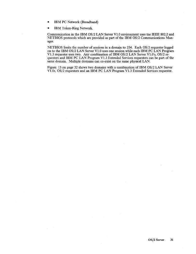
• IBM PC Network (Broadband)
• IBM Token-Ring Network.
Communication in the IBM OS/2 LAN Server Vl.O environment uses the IEEE 802.2 and NETBIOS protocols which are provided as part of the IBM OS/2 Communications Manager.
NETBIOS limits the number of sessions in a domain to 254. Each OS/2 requester logged on to the IBM OS/2 LAN Server VI.O uses one session while each IBM PC LAN Program VI.3 requester uses two. Any combination of IBM OS/2 LAN Server VI.O's, OS/2 requesters and IBM PC LAN Program VI.3 Extended Services requesters can be part of the same domain. Multiple domains can co-exist on the same physical LAN.
Figure 13 on page 32 shows two domains with a combination of IBM OS/2 LAN Server VI.Os, OS/2 requesters and an IBM PC LAN Program VI.3 Extended Services requester.
OS /2 Server 31

3.4.1.1 A Typical LAN Configuration
Domain 1 : Domain 2
: PCLP 1.3 : Requester : User ID 1
OS/2 Requester User ID 2
OS/2 Requester User ID 1 LAN (1)
~ ..... ;..L.---1---,-1----, I-- OS/2
:----.-------'
OS/2 Domain Controller
1 = One of: PCNET Baseband PCNET Broadband Toket"-Ring
I : OS/2 Srv. : Domain : Controller
Figure 13. An IBM OS/2 LAN Server Vl.O Environment
3.4.2 Host Connectivity
Server
Iprinterl
Workstations on the LAN are able to access host resources residing on both IBM System/370 hosts and ASCII hosts. The Communications Manager provides, as a standard feature, the following support:
• For accessing IBM System/370 hosts
• 3270 Terminal Emulation
• APPC support.
• For accessing ASCII hosts
• Asynchronous Terminal Emulation.
A brief description of the support provided by the Communications Manager is provided below:
• 3270 Emulation - when configured for 3270 host access the workstation emulates a 3274 (PU type 2) with up to 5 3278/9 (LU type 2) terminals attached. Support is provided for 3278/9 Models 2, 3, 4 and 5 which have differing screen sizes and characteristics. In order to access 3270 host applications, the Communications Manager requires the gateway services of either a 3174 terminal controller or 37xx communications controller. These can either be remotely attached as in Figure 14 on page 34 or locally attached as in Figure 15 on page 35. An alternative to using either a 3174 or a 37xx as a gateway is to use the integrated Token-Ring Network Subsystem Controller (TRNSC) of a 9370. This is shown in Figure 16 on page 36.
• APPC Support - the Communications lVlanager also includes support for Advanced Program-to-Program Communications (APPC). APPC enables. a peer-to-peer connection between a personal computer and another APPC capable system, such as an IBM System/370 host or in fact another personal computer, for the purposes of program-to-program communications. The OS/2 Extended Edition Vl.I Communications Manager supports an SNA APPC node (combination of PU type 2.1 and LU
32 LAN Server Guide

type 6.2) and is architected to support up to 65,025 APPC (LU type 6.2) host sessions. The current implementation provides support for either:
• 5 LU type 2 and 119 LU type 6.2 host sessions, or
• 124 LU type 6.2 host sessions.
The 37xx Communications Controller is the only gateway which is supported. It can either be link-attached or channel-attached as in Figure 17 on page 37. An alternative configuration is shown in Figure 18 on page 38 which requires a customer-written router program to provide gateway services.
• ASYNC Communications - one of the features of the IBM OS/2 LAN Server Vl.O is its ability to share serial devices, such as ASYNC adapters, across the LAN. Depending on the personal computer capabilities, the OS/2 Extended Edition Vl.l Communications Manager can support up to 'three ASYNC adapters which can be used by workstations on the LAN wishing to access ASCII hosts. This is shown in Figure 19 on page 39.
Currently the only gateways that provide IBM System/370 host access for LAN-attached OS/2 Extended Edition Vl.l workstations are those mentioned above. However, a'statement of direction has been made to the effect that an OS/2-based SNA LAN gateway will be provided.
as /2 Server 33

3.4.2.1 Typical Configurations Using 3270 Terminal Emulation
LAN Host Horkstation Connection Gateway Connection Host Environment
< >< >< >< >< >
3270 Camms Mgr. - V Application 3270 3174-xlR Emulation 3174-x2R
Token-Ring 37xx I OS/2 EE
8-/-8 SOLC link
N T C A P M -
B = Modem
Figure 14. 3270 Host Access Using a Remote 3174 or 37xx as a Gateway
Notes to the above diagram:
1. The OS/2 EE workstation can also be configured as an OS/2 requester or running the IBM OS/2 LAN Server V1.0 program.
2. The Communications Manager emulates a 3274 with up to 5 x 3278/9 terminal sesSlons.
3. The models of 3174 which can provide link-attached gateway services are the OIR, SIR, 02R and 52R.
4. The 3I74s require a gateway feature to be added and will support a single host link at speeds of up to 64 Kbps.
5. The 37xx can either be a 3720,3725 or 3745 which has been appropriately configured.
6. The 37xx can support multiple host links at speeds of up to 64 Kbps. Higher speeds are also supported
7. Examples of 3270 applications are TSO and CICS.
8. The above configuration is only supported in an IBM Token-Ring Network environment.
34 LAN Server Guide
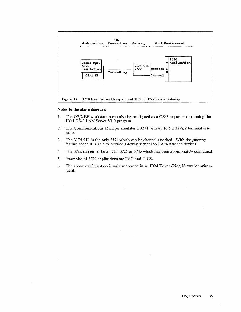
LAN Horkstation Connection Gateway Host Environment
< > < > <---> < >
3270 Comms Mgr. V Application 3270 3174-01L T Emmulation 37xx ======= A
I OS/2 EE TokerrRing M
Channel
Figure 15. 3270 Host Access Using a Local 3174 or 37xx as a a Gateway
Notes to the above diagram:
1. The OS/2 EE workstation can also be configured as a OS/2 requester or running the IBM OS/2 LAN Server V1.0 program.
2. 1.'he Communications Manager emulates a 3274 with up to 5 x 3278/9 terminal sesSIons.
3. The 3174-01L is the only 3174 which can be channel-attached. With the gateway feature added it is able to provide gateway services to LAN-attached devices.
4. The 37xx can either be a 3720, 3725 or 3745 which has been appropriately configured.
5. Examples of 3270 applications are TSO and CICS.
6. The above configuration is only supported in an IBM Token-Ring Network environment.
as /2 Server 35

LAN Host with Horkstation Connection Integrated Gateway
< >< >< >
9370
3270 Comms Hgr. T V Application 3270 R T ElIRJlation N A
I OS/2 EE Token-Ring S H
C
Figure 16. 3270 Host Access Using the 9370's Integrated Gateway Support
Notes to the above diagram:
1. The OS/2 EE workstation can also be configured as an OS/2 requester or running the IBM OS/2 LAN Server Vl.O program.
2. The Communications Manager emulates a 3274 with up to 5 x 3278/9 terminal sessions.
3. The integrated Token-Ring Network Sl,lbsystemController (TRNSC) consists of a token-ring adapter, a Communications Processor and microcode.
4. Examples of 3270 applications are TSO and CICS.
5. The above configuration is only supported in an IBM Token-Ring Network environment.
36 LAN Server Guide

3.4.2.2 Typical Configurations Using the APPC Support
LAN Horkstation Connection Gateway Host Environment
< >< > <--> < >
Comms Hgr. APPC Support
I OS/2 EE
I--T-ok-e-n--R-in-g--B Link or
Channel
CICS V T A H
Figure 17. Program-to-Program Communication Using a 37xx as a Gateway
Notes to the above diagram:
1. The OS/2 EE workstation can also be configured as an OS/2 requester or running the IBM OS/2 LAN Server V1.0 program.
2. The Communications Manager supports up to 124 APPC sessions.
3. The 37xx can either be a 3720, 3725 or 3745 which has been appropriately configured.
4. The 37xx can either be link- or channel-attach~d.
5. APPC support is provided under CICS.
6. The above configuration is only supported in an IBM Token-Ring Network environment.
OS/2 Server 37

LAN Horkstation Connection Gateway
Host COI'YleCt ion Host Environment
<:-----> <----> <.----> <-----> <------->
APPC Comms Mgr. r-- V Application APPC Comms Mgr. Support APPC
I OS/2 EE Token-Ring Router 8-/-8
SDLC link
N T C A P M
'--
B = Modem
Figure 18. APPC Using a Router as a Gateway
Notes to the above diagram:
1. The OS/2 EE workstation can also be configured as an OS/2 requester or running the IBM OS/2 LAN Server V1.0 program.
2. The Communications Manager provides support for up to 119 LU6.2 sessions as a standard feature.
3. The router can run in any OS/2 Extended Editi-.:-n V1.1 capable workstation.
4. The APPC router program must be user-written.
5. The APPC router workstation requires an SOLC card and will support speeds of up to 19200 bps.
6. The above configuration is only supported in an IBM Token-Ring Network environment.
38 LAN Server Guide

3.4.2.3 A Typical Configurations Using Asynchronous Terminal Emulation
LAN Horkstation Connection Gateway
Host Connection
Host Environment
<-----> <:----> <:----> <-----> <----->
Comms Mgr. ASYNC Comms
I OS/2 Req. Token-Ring PCNET
OS/2 EE LAN Server Vl.O
8--/--El ASCII Host
ASYNC
EJ = Modem
Broadband PCNET
Baseband
Start/Stop Link
Figure 19. ASCII Host Access Using the LAN Servers serial ports
Notes to the above diagram:
1. The OS/2 requester station uses the ASYNC ports on the IBM OS/2 LAN Server V 1.0. Link characteristics are selected via the Communications Manager.
2. The IBM OS/2 LAN Server Vl.O can have up to three ASYNC adapters which can be shared on the network.
3. The ASYNC start/stop link can run at speeds of up to 19200 bps.
4. The above configuration is supported in an IBM Token-Ring Network, an IBM PC Network (Broadband) and an IBM PC Network Baseband environment.
3.5 Compatibility and Co-existence Typically the IBM OS/2 LAN Server Vl.O receives requests for resources from OS/2 requester workstations. In addition, it also supports requests for flie and print resources from IBM PC LAN Program Vl.3 requesters. The latter are not able to access certain IBM OS/2 LAN Server Vl.O resources such as serially attached devices nor are they able to perfonn the NET RUN, NET MOVE and NET COPY functions. No support is available for IBM PC LAN Program Vl.3 servers to communicate with IBM OS/2 LAN Server Vl.O and they cannot exist within the same domain.
3.6 Interfaces
3.6.1 End-User Interface
The IBl\l OS/2 LAN Server Vl.O and OS/2 requester offer the user the choice between interfacing with the system via commands, batch flies or menus.
The command line interface which is the basis for automating operations via batch flies, includes the following categories of command:
OS /2 Server 39

• Network startup and shutdown
• U sing and sharing resources
• Managing print queues and serially attached devices
• Network nnessaging
• Network adnninistration
• Network utilities
• Running the full-screen user interface.
The full-screen interface is provided by the IBM OS/2 Presentation Manager and is based on OS/2 EZ-VU. It can be driven via either the keyboard or a nnouse, or both. The screen formats are similar to those presented in an IBM PC LAN Progrann V1.3 Extended Services environnnent but nnore closely resennble the screen layouts defmed by Systenns Application Architecture 11 (SAA). They include action bars, pull-down panels, pop-up panels, warning panels, error panels and help panels.
3.6.2 National Language Support
The IBM OS/2 LAN Server VI.O provides national language support for the three nnajor language groups, nannely:
• Left-to-right single-byte character sets (SBCS)
• Right-to-left single-byte character sets (SBCS)
• Double-byte character sets (DBCS).
In other words, support is provided for the full range of national languages supported by OS/2 Extended Edition VI.I. This includes all panels and documentation supplied with the product. There are no language dependencies within the executable code.
3.7 Security Services Security Services include:
• Multiple levels of access rights to protect:
• Individual fues • Directories • Printers • Serially attached devices
• User, group and administrator level authorizations
• Encrypted logon passwords.
Access rights are nnanaged by the network adnninistrator, who can create and update user profiles, defme groups and grant or revoke access rights. The adnninistrator can set access rights at a user, group and network level, on either an include or exclude basis. Possible access rights include:
• None • Execute
11 Systems Application Architecure is a trademark of the International Business Machines Corporation.
40 LAN Server Guide

• Read • Update • Alter.
The execute attribute gives the ability to run a program and provides a mechanism to prevent copying of the program.
The administrator can limit how many simultaneous users can access the same shared resource. This function provides a means of controlling the number of simultaneous users of a program.
3.8 Performance Considerations The IBM OS/2 LAN Server Vl.O performance depends on a number of factors. These include:
• Available hardware
• LAN configuration
• Number of concurrent users
• Workload proflle
• Tuning parameters in effect
• Whether the server is dedicated or not.
Key hardware considerations will be the type and clock speed of the system unit processor, the amount of memory available for buffers and disk cache, and the access times of the fixed disk installed on the disk server.
Configuration parameters are available to control factors such as the number of buffers, memory used for disk cache, segment swapping characteristics, system priority and time slice designations.
3.9 Management The IBM OS/2 LAN Server Vl.O provides a number of administration and control features of its own. These facilities which must be performed from an IBM OS/2 LAN Server Vl.O workstation are reviewed in "Administration and Control" on page 29.
In addition the LAN adapter cards installed in the different workstations are able to generate error and status information which can be captured by a LAN management application. In those environments where host access is required, the gateway may be able to send alerts to a host-based management application.
A planned enhancement for the IBM OS/2 LAN Server Vl.O is to have Communications and Systems Management alerts sent to NetView via the C&SM support in the OS/2 Extended Edition V 1.1 Communications Manager.
As with IBM PC LAN Program VI.3 the task of administering software on the LAN can be reduced by making use of the RIPL facilities for personal computer DOS-based workstations.
Under certain circumstances workstations are able to receive program and table updates which have been sent from NetView Distribution Manager running on a IBM System/370 host.
Further d~tails are contained in "Management" on page 7.
OS/2 Server 41

42 LAN Server Guide

4.0 AS/400 PC Support
4.1 Overview
The IBM AS/40012 PC Support is a set of programs that expand the capabilities of the IBM Personal Computer and IBM Personal System/2 to include system resources and server functions. The implementation is similar in concept to that of ECF (see "Enhanced Connectivity Facilities VI.I" on page 57) in that both of them provide servers which allow personal computers to access host resources as though they were their own. PC Support provides the user, via a simple menu interface, with a number of mostly independent functions such as:
• Run DOS commands
• Send and receive messages
• Data transfer between a personal computer and the AS/400
• File sharing
• Print sharing
• Access to AS/400 data bases
• Office integration
• Gateway support
• Coresidence with IBM PC LAN Program V1.3.
In addition the IBM AS/400 PC Support includes support to allow attached personal computers to emulate AS/400 displays, printers or graphics workstations.
4.2 Basic Functions The IBM AS/400 PC Support operates in a personal computer DOS environment (a statement of direction has been made to the effect that support will be. provided under OS/2) and provides the integration of personal computer functions and multi-user system functions in what is known as a "seamless" environment. That is, the personal computer user should be unaware of whether the application is running on the workstation or on the AS/400.
The user has the chOlce of running PC Support on its own or together with the organizer. PC Support can be used for applications such as data transfer, flie sharing, print sharing and sending and receiving messages. The PC Support organizer adds the ability to run frequently used personal computer applications such as spreadsheets and AS/400 applications such as advanced office and working with editors.
12 ASj400 is a trademark of the International Business Machines Corporation.
AS/400 PC Support 43

Communication between the personal computer and the AS/400 system uses Advanced Program-to-Program Communications/Advanced Peer-to-Peer Networking (APPC/APPN). On the personal computer, requests are generated to access one of the server functions on the AS/400. This request is transmitted by a router over the LAN using APPC/ APPN for data communications. There is no router on the host but instead the request is handled by the AS/400 APPC/APPN support which passes it through to the server. Responses are returned over the reverse route.
4.2.1- Run DOS Commands
It is possible to run personal computer DOS commands from either the PC Support menu or the PC Support organizer menu.
By making the appropriate selection on the PC Support menu the user is presented wttn the DOS command prompt and can then issue DOS commands. Upon completion the user can return to the PC Support menu.
The PC Support organizer interface allows the user to issue DOS commands from its menu or to access the DOS command prompt.
4.2.2 Message Function
IBM AS/400 PC Support users are able to communicate with other personal computer and AS /400 users located on the LAN or elsewhere in the network by sending and receiving messages. Users can either use the PC Support message function or the AS/400 message functions to send up to 512 characters of message to a specific user, a distribution list or as a broadcast. Recipients have the option of being notified or interrupted by receipt of a message. Included in a message is the sender's ID and date and time the message was received. As implied, the user need not be logged on in order to receive a message. When he or she does log on they will be informed that a message is waiting.
4.2.3 Shared Folders
Shared folders were designed to store text documents processed by the AS/400 Office and DisplayWrite 4 functions. They can also be used to store personal computer applications and data in PC format as though they were personal computer fixed disks. Information can be stored and organized according to "folder paths" which are similar to personal computer directory paths.
Shared folders allow personal computer users and AS/400 users concurrent access to the same folder. Data can be copied from personal computer documents stored in a folder to AS/400 data bases and vice versa. Personal computer applications that support byte level locking will allow more than one personal computer user concurrent use of the information in a folder.
Documents and folders may be protected by the AS/400 security features.
4.2.4 Virtual Print
PC Support allows the user to make use of the AS/400 printers. The term virtual printer means that although the printer is attached to the AS/400, the user can use it as if it were a PC printer. -
In addition PC Support, via the \Vorkstation Function, allows the user to set up personal computer printers as AS/400 printers thus enabling multiple personal computers to share them.
44 LAN Server Guide

Up to three virtual printers, which can be any combination of AS/400 system printers or personal computer printers emulating AS/400 system printers, can be assigned.
When using the PC Support virtual printer support, output is directed to an AS/400 spool fue. If, the output is to be printed on a personal computer printer it is left in ASCII format. However, if it is to be printed on an AS/400 printer, the data is converted to EBCDIC and control information is added.
4.2.5 Data Transfer
PC Support works with flies called data base files. The AS/400 differentiates between physical data base files which contain fixed-length records and logical data base files. The latter contain descriptions of record formats used to access fields in one or more physical fues.
The transfer function allows data to be transferred to or from the personal computer. Data received at the personal computer can be displayed, printed or stored in a personal computer flie while data transferred to the AS/400 can be sent to an AS/400 physical data base fue. The AS/400 Distributed Data Management (DDM) facility allows fues to be transferred to and from remote AS/400's.
A menu interface prompts the user in creating, modifying, and running transfer requests. When transferring data from the AS/400 to the personal computer the user is prompted via a menu interface to build SQL-like transfer requests that can select data from multiple flies according to specified criteria and return it to the personal computer in one of the following formats:
• ASCII text • DOS random • BASIC sequential • BASIC random • DIF13 • No conversion.
Transfer requests can be saved, recalled and used again without prompting.
4.2.6 Workstation Function
The IBM AS/400 PC Support Workstation Function provides support to allow attached personal computers to emulate AS/400 displays, printers or graphics workstations. Each workstation or printer being emulated is called a session and uses a unique workstation ID on the AS/400. Each personal computer can have up to five concurrently active display or printer sessions to both local and remote AS/400's. The user can Hot key between the different sessions.
The workstation function includes keyboard arrangements for the different emulations. The.se can be modified by the user. However, only one arrangement is active for all five seSSlOns.
In addition the workstation function allows the user to set up personal computer printers as AS/400 printers thus enabling multiple personal computers to share them.
4.2.7 Organizer
The organizer runs in one workstation function session and allows the user to run AS/400 applications as well as PC Support and other personal computer applications from a single
13 DIF is a trademark of LOTUS Development Corp.
AS/400 PC Support 45

menu. The default organizer menu can be modified with the Screen Design Aid (SDA) to include any personal computer or AS/400 function that is frequently used by the user. The standard menu includes:
• AS /400 Office
• Work with documents - create, check spelling, print, send, etc.
• Profile options - for selecting editors (DisplayWrite 4 or AS/400 Office) and changing document profiles
• AS/400 PC Support
• Host system tasks for AS/400 PC Support
• PC commands.
When using the AS/400 Office, the- PC Text Assistfunction provides editing capabilities, such as full horizontal and vertical scrolling, and underline and bold marking functions.
The host system tasks menu allows the user to work with AS/400 documents and folders, copy personal computer documents to an AS/400 data base and vice versa.
4.3 Operating Environment This section deals with the hardware and software prerequisites for both the AS /400 and personal computer. LAN components, other than attachment requirements, are not included.
4.3.1 Prerequisite Hardware
Minimum AS/400 system requirements:
• Any model of the AS/400 system • 6.6 MB of auxiliary storage • Token-Ring Network Subsystem and adapter.
Minimum personal computer requirements:
• Any supported IBM Personal Computer or IBM Personal System/2 • 512 KB (640 KB is recommended) • One diskette drive • Keyboard • Monochrome, color or graphics display • Appropriate token-ring network adapter.
4.3.2 Prerequisite Software
For the IBM AS/400 system:
• IBM Operating System/40014, or later
• IBM AS/400 Office (if used as editor of choice).
For IBM Personal Computers:
• IBM DOS Version 3.3, or later • IBM DisplayWrite 4 (if used as editor of choice) • IBM LAN Support Program Vl.02 or later.
46 LAN Server Guide

4.4 Connectivity The AS/400 system offers a wide variety of communications and connectivity options, and can operate in a number of different environments:
• As a host system to remote workstations such as 5250s, 3270s, personal computers and fmancial devices
• As a peer system to other AS/400s, System/36s, System/38s, and in fact personal computers
• As a remote system in a System/370 controlled network.
In addition it provides support for a number of data link protocols which include:
• SDLC • BSC • Asynchronous • X.25 • Token-Ring.
In this section we limit the discussion to those options that are available to the PC Support user who is attached to a LAN and has a need to access host-based resources residing within either an APPN network or a System/370 controlled network.
4.4.1 LAN Connectivity
The only LAN supported for the IBM AS/400 PC Support environment is the IBM Token -Ring Network. Within this environment, communication between the personal computers and an AS/400 uses Advanced Program-to-Program Communications/Advanced Peer-to-Peer Networking (APPC/APPN) support. Each AS/400 can have up to two Token-Ring adapters instilled with each adapter being able to support up to 128 personal computers. Ignoring the performance implications, this gives a total of 256 workstations that can be supported.
IBM AS/400 PC Support users on an IBM Token-Ring Network may directly access six AS/400 systems also attached to an IBM Token-Ring Network. In a mixed environment of AS/400 and System/3615 units, a Coexistence Enhancement Feature for PC Support/36 is required which will allow users concurrent access to data on any AS / 400 or System/36 on the LAN.
4.4.1.1 A Typical LAN Configuration
The typical scenario for the AS/400 PC Support is represented in the following figure:
14 Operating System/400 is a trademark of the International Business Machines Corporation.
15 System/36 is a trademark of the International Business Machines Corporation.
AS/400 PC Support 47

PC Support PC Support
Requester Requester
PC Support
Requester Token-Ring
PC Support
Requester
Figure 20. AS/400 PC Support
4.4.2 Host Connectivity
Shared folder
APPC/APPN is the AS/400 (also System/36) implementation of the SNA LU type 6.2 and Node type 2.1 architectures. Support is provided for peer systems to communicate in an easy-to-use, dynamic fashion and to provide advanced functions such as directory searches and dynamic route selection, based on class of service.
Each personal computer within an APPC/APPN network can concurrently access the resources on up to 32 AS/400 and System/36 sy~tems wp;<;h can be located anywhere in the network. Functions such as display sessions, assigned virtual printers and shared folders are based on conversations. The PC Support user can have up to 40 conversations distributed among the 32 AS/400's and System/36's. An example showing a mixed environment of AS / 400' s and System/ 36' s can be seen in Figure 21 on page 49.
The OS/400 SNA device emulation allows the PC Support user to communicate with 3270 type application programs, such as TSO and CICS, on an IBM System/370 host. The AS/400 can be connected to an existing SNA 3270 network and appears to the IBM System/370 host as a 3x74 Control Unit with attached displays and printers. Displayemulation is provided for 3278 Model 2 terminals while printer emulation is provided for one of 3284, 3286, 3287, 3288 or 3289 printer. Printer emulation facilitates printing of flIes, sent from the System/370 host, on a printer attached to the AS/400. The AS/400 operates as a secondary station (that is, its terminals can log on to the System/370 but not vice versa, unless programs such as HCF and DHCF are used) on a point-to-point switched (includes Token-Ring LAN) or non-switched line, or on a multipoint non-switched line.
Figure 22 on page 50 shows how a PC Suppon user can access a 3270 type application where the AS/400 is link-attached to the IBM System/370 host.
Figure 23 on page 51 shows the situation where both the AS/400 and IBM System/370 host (9370) are directly attached to the LAN and the PC Support user is able to access 3270 type applications via the 3270 device emulation running in the AS/400.
48 LAN Server Guide
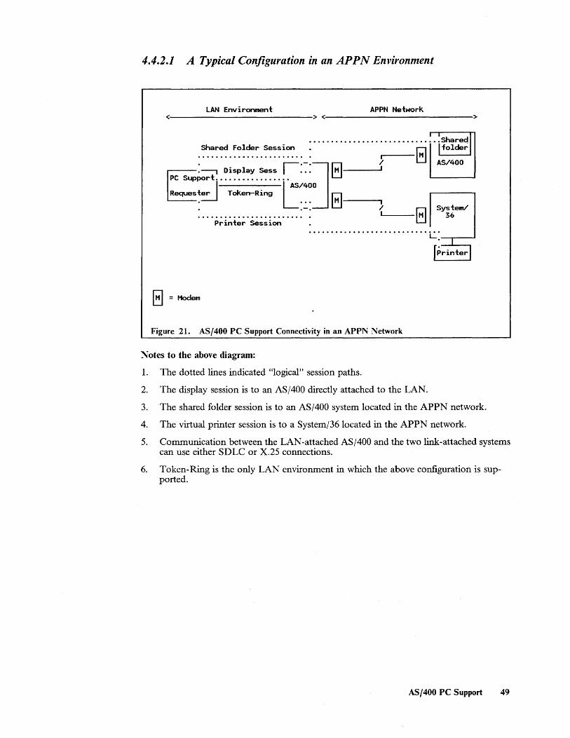
4.4.2.1 A Typical Configuration in an APPN Environment
LAN Environment APPN Network <----------------------------> <---------------------------->
Shared Folder Session :·······················~~·i~~1 : .................. r-:-:.:-:] r:l } M AS/400
....-----.--, Display Sess I • • • ~ I :::::l' ~~~~~~. T AS/400 Iul 1.--__ • ... ~ I
: ...................... : . { r;;l sy~!em/ Printer Session LJ ........................... L: ---'1""'----'
fprinterl
E] = Modem
Figure 21. AS/400 PC Support Connectivity in an APPN Network
Notes to the above diagram:
1. The dotted lines indicated "logical" session paths.
2. The display session is to an AS /400 directly attached to the LAN.
3. The shared folder session is to an AS/400 system located in the APPN network.
4. The virtual printer session is to a System/36 located in the APPN network.
5. Communication between the LAN-attached AS/400 and the two link-attached systems can use either SDLC or X.25 connections.
6. Token-Ring is the only LAN environment in which the above configuration is supported.
AS/400 PC Support 49

4.4.2.2 Typical Configurations Using 3270 Device Emulation
LAN Environment Sys tem/3 70 Controlled Network <---------------------------> <--------------------------->
System/370 . AS/400 .r"T.-----,
WorkstatIon I I •.••••••• ~ .•.. 3270 r-----...." • • • • • • • • • • • • • • r- V Appl ication
PC Support i ............. ··1· 3270 ~--/--~ ~ ! Requester I Token-Ring device ~ ~ P M
emul. SOLC link '-
El = Modem
Figure 22. AS/400 3270 Device Emulation
Notes to the above diagram:
1. The dotted line indicates a "logical" session path.
2. The PC Support user is using the OS/400 SNA 3270 Device Emulation program for accessing the 3270 application running in the System/370.
3. Examples of 3270 type applications are CICS, TSO and CMS.
4. Token-ring is the only LAN environment in which the above configuration is supported.
50 LAN Server Guide

LAN Environment <.~-------------------------------->
AS/400
3270 device emul.
9370
: ••••••••••••• TSO PC Support .• : ....-----'------, T V t-----I
R T Requester N A
S M C
Figure 23. AS/400 3270 Device Emulation
Notes to the above diagram:
1. The dotted line shows the "logical" session path.
2. Both the 9370 (System/370) and the AS/400 are directly connected to the LAN.
3. TRNSC stands for Token-Ring Network Subsystem Controller and, as for the AS/400, is an integral component of the 9370.
4. The PC Support user is using the OS/400 SNA 3270 Device Emulation program for accessing the 3270 application running in the System/370.
5. Token-ring is the only LAN environment in which the above configuration is supported.
4.5 Compatibility and Coexistence When compared to PC Support/36, the IBM AS/400 PC Support has incorporated some major changes in its implementation. The AS/400 router in the personal computer no longer communicates with a router in the AS/400 system; instead it communicates directly with the APPC support. This router can also communicate with APPC on a System/36 and will allow the user to access System/ 36' s using one or more of the five sessions supported by the IBM AS/400 PC Support Workstation Function. In order to use the other PC Support functions like shared folders, virtual print, message, function, transfer function or the organizer, it is necessary to install a Coexistence Enhancement Feature PRPQ, for PC Support/36, on the System/36.
In addition, migration aids are provided for migrating PC Support/36 and PC Support/38 to AS/400 PC Support. PC Support/38 is not discussed here as it is unable to directlyattach to the LAN and therefore cannot co-exist with AS/400 PC Support in a LAN environment.
The IBM AS/400 PC Support and the IBM PC LAN Program V1.3, when the latter is running Base Services, may run concurrently on a single personal computer. Two configurations are possible:
AS/400 PC Support 51

• The workstation can be configured as a Base Services user, in which case it can have access to both personal computer disks on a PCLP 1.3 server and ASj400 shared folders.
• The workstation can be configured as a Base Services server and can now provideaccess to both personal computer and ASj400 resources such as disks and shared folders.
Some limitations exist in this environment, the key ones being:
• Workstation Function printer emulation cannot be concurrently directed to a personal computer printer that is also being used as a PC LAN Program network printer.
• When sharing ASj400 system resources as network resources, the PC LAN Program cannot share virtual printer resources with folder resources at the same time.
4.6 Interfaces
4.6.1 End User Interface
The IBM ASj400 PC Support provides what is commonly referred to as a "seamless environment." The intention is to make the differences between personal computer and ASj400 operations transparent to the end user. The user is presented with a menu interface which makes use of pull-down and pop-up windows, cursor-sensitive help, and lists of selectable actions, options, items and function keys.
4.6.2 Programming Interfaces
Personal computer applications wishing to use IBM ASj400 PC Support functions can do so by using an Application Programming Interface (API). An API provides a standardized interface that allows well-designed, modular applications that adhere to the interface to be freely exchanged.
There are two APIs, one providing an interface to the transfer function, and the other giving access to certain workstation function services.
The transfer function API allows transfer requests to carry descriptions of the information to be transferred and to specify the format for returned information.
The workstation function API allows user-written programs to manipulate the characteristics as well as well as the operation of the workstation function session. This API is supplied as an PRPQ.
4.7 National Language Support Basic national language support is required to accommodate country specifics such as keyboard layouts, special characters, country-specific rules (for example, date formats) and the use of national languages to interact with the user.
There are three major components of the IBM ASj400 PC Support:
• Program code - the same for all countries except where double-byte character sets (DBCS) are used.
• Machine-Readable Information (MRI) - online information, help text and screens, which are translated into different national languages using specific ASCII code pages.
• Documentation supplied with the product.
52 LAN Server Guide
National language support is provided for the following countries and areas:
• Belgium • Canada • Denmark • Finland • France • Germany • Great Britain • Iceland • Italy • Japan • Korea • Latin America • The Netherlands • Norway • Portugal • Spain • Sweden • Switzerland • Taiwan • United States of America.
The PC Support initialization program (INZPCS) requests three parameters: keyboard ID, EBCDIC code page and ASCII code page, and support is provided for the commonly used code page pair combinations.
Only one national language version of IBM AS/400 PC Support may be installed.
4.8 Security The IBM AS/400 PC Support uses the security features of the IBM AS/400 system. These are based on a number of different levels.
The lowest level of security is the level shipped with the system which provides no control over who can log on and access resources. Password level and resource level require that the user is registered on the system. Before a user can log on, a profile must exist for his or her user ID and the password supplied at logon time must match that contained in the profile.
At a resource level, "rights" must be assigned in order for the user to perform certain functions. These include *USE, *OPER, *READ, *ADD, *OBJMGT and *DEL, and determine which resources the user can access and what functions he or she can perform. In addition, it is possible when running resource level security, to restrict privileged users to certain display stations for performing privileged operations.
Menu security is another means of restricting the user's activities. Only those menu selections which have been specillcally authorized will be available to the user.
Finally, a facility is provided to allow user exit programs to perform any further security checks that may be required.
4.9 Performance ConsideJ"ations The same general performance considerations apply to IBM AS/400 PC Support as they do to the other server implementations. These include factors such as:
• Model of AS/400 selected
• Number of concurrent users
AS/400 PC Support 53

• \Vorkload proftle
• \Vhether the server is dedicated or not
• LAN configuration.
Some more specific factors include the number of conversations, the number of system drives, cache buffering, ftle management and tuning parameters.
Each inactive or active conversations (for example, assigned shared folders), and each system drive uses system resources and can thus impact performance. By terminating inactive conversations and assigning a single system drive with multiple shared folders, rather than assigning multiple shared folder drives, performance can be improved.
In a mixed AS/400 PC Support and PC Support/36 environment it is important to select the correct router. The AS/400 PC Support router will give the best performance when an AS/400 is the primary system. However, when a System/36 is the primary system it is necessary to install a modified System/36 router in order to achieve optimum performance.
There is often a trade-off between performance and the additional functions. Shared folders provide capabilities to a personal computer user that PC disk flies do not (that is, simultaneous access/update by multiple users, system security, network/change management facilities, etc). However, PC diskflies generally perform better than shared folders, particularly as the number of concurrent AS/400 users increases. The impact on performance will largely depend on the functions being performed.
Tuning parameters are available to control factors such as:
• Frequency and persistence of polling
• How soon and how often a frame is retransmitted
• How often acknowledgements are to be sent and received
• Specification of priority traffic.
4.10 Management The AS/400 implements very powerful LAN management capabilities. In an APPN environment the AS /400 can act as a focal point or alternatively, can forward alerts to another focal point. In a LAN environment the AS/400 implements the Ring Error Monitor (REM) function (see "Management" on page 7).
Three recording levels are provided for collecting error type information. With recording set to the highest level, all error and status information relating to a single segment TokenRing Network will be translated into messages. These messages are then put in the system operator message queue and marked in the message history fue. Based on a flag setting, set either by default or by the operator, cenain of the messages will generate alerts which can be forwarded to a focal point. Alerts can be logged, retrieved and deleted.
In addition, one of the LAN Manager products as specified in "Management" on page 7 can be run on the LAN to provide those functions which are not available from the AS/400.
To reduce the overhead of administering the IBM AS/400 PC Support environment, an AS/400 PC Support Update Function (PCSUPDT) is provided. It is intended to ensure that the latest level of PC Support is running on all personal computers. However, the implementation allows for other program code and data to be distributed. When PC Support is initialized on the personal computer, PCSUPDT checks the date of specified AS/400 folders against that of specified directories on the personal computer. If there is a mismatch, an update will take place.
NetView Distribution Manager (NetView DM), running in an IBM System/370 host is also able to distribute software and data to personal computers. It can send this software and
54 LAN Server Guide

data to personal computers that are running the IBM Personal Computer Distributed Systems Node Executive (PC/DSNX) program. The network configuration can consist of a System/370 as a focal point, any number of AS/400's or System/36's as intermediate nodes, and any number of personal computers as end points.
The AS/400, being a host environment, should also have procedures in place for performing regular backups and generally ensuring that the system is available on a continuous basis.
4.11 PC Supportj36 AS/400 PC Support and PC Support/36 are very similar in the way they appear to the end user. A few differences exist between the two implementations and they can be categorized as differences in:
• Functional capabilities
• Number of users supported
• Operating environment
• Implementation.
This section mentions the most significant of these differences.
4.11.1 Functional Capabilities
The only functional difference between the two systems is that virtual disk (this includes virtual diskette) is not supported by the AS/400.
For users migrating from a System/36 environment to an AS/400 environment, a migration aid is provided for converting virtual disks to shared folders.
4.11.2 Number of Users Supported
Ignoring performance implications, the AS/400 PC Support can attach up to 128 active stations per token-ring adapter (token-ring line) giving a total of 256 active connections to other stations. PC Support/36 on the other hand can attach up to 50 active stations per token-ring adapter, giving it a total of 100 active connections.
4.11.3 Operating Environment
Differences exist hoth In the hardware and the software required to run PC Support.
4.11.3.1 Hardware Requirements
The token-ring adapters on the AS/400 are integrated into the system unit. Up to two adapters can be installed.
This is different from the System/36 environment in which requirements are dependent on the model in question:
• The System/36 Model 5363 can be fitted with an integrated token-ring network adapter (up to two)
• The System/36 Model 5364 uses the attached PC/AT16 which can be fitted with a Token-Ring Network adapter II (up to two)
• The System/36 Models 5360 and 5364 require the following:
AS/400 PC Support 55

• The System/36 LAN Attachment Feature - installed on the System/36 (includes a standard length cable for attachment to the PC/AT)
• A dedicated PC/AT with:
A 512Kb RAM A Keyboard A Display and associated display adapter A System/36 LAN attachment adapter - for connecting the PC/ AT to the
System/36 A IBM Token-Ring Network Adapter II (up to two).
4.11.3.2 Software Requirements
AS/400 PC Support requires:
• Operating System/400 (OS/400)
PC Support/36 requires:
• System/36 Systems Support Program
• Interactive Data Defmition Utility (IDDU)
• System/36 LAN Communications Program.
The workstations running AS/400 PC Support require DOS 3.3 or later and IBM LAN Support Program, while the workstations running PC Support/36 require DOS 3.2 or later.
4.11.4 Implementation
Some major changes are included in the architecture of the AS/400 PC Support, the most significant being that the AS/400 router on the personal computer no longer communicates with a router on the host side; instead it communicates with an APPC communication program. This new router is able to communicate with APPC on the System/36 and a modified PC Support/36 router is available to communicate with APPC in the AS/400. Thus support is provided for a mixed environment of System/36's and AS/400's.
16 PC/AT is a registered trademark of the International Business Machines Corporation.
56 LA" Server Guide

5.0 Enhanced Connectivity Facilities Vt.t
5.1 OvervieJv The IBM Enhanced Connectivity Facilities Vl.I (ECF) consists of a set of IBM-provided server and requester programs. These programs are designed to 'connect IBM Personal Computer and IBM Personal System/2 users to IBM System/370 host data bases and flies over a suitably configured communications link and thus extend the personal computing environment to include host resources.
The following highlights are provided by the IBM Enhanced Connectivity Facilities VI.I:
• Extension of personal computer resources to include those of the host system, namely:
• Virtual disk
• Virtual flie
• Virtual print
• File transfer capabilities
• Host data services providing access to DB2 and SQL/DS relational data bases as well as DL/I data, and VSAM, CMS, and sequential flies
• Initiation of host procedures, commands, and programs from the IBM Personal Computer or IBM Personal System/2
• Both a full-screen menu-driven interface and a command-driven interface for the personal computer user
• A consistent application development interface known as the Server-Requester Programming Interface (SRPI).
The SRPI can be used to develop additional user-written servers and requesters if desired.
5.2 Basic Functions The IBM-provided servers/requesters are written using the same SRPI that is provided for end-user application development. They include:
• The IBM Personal Computer or IBM Personal System/2 Requesters
• The IBM TSO/E Servers for MVS/XA hosts
• The IBM CMS Servers for VM/SP hosts.
The IBM Enhanced Connectivity Facilities Vl.I requesters are currently supported only in a personal computer DOS environment. A statement of intent has been made to the effect that support will be provided under OS/2.
ECF 57

The IBM Enhanced Connectivity Facilities Vl.I requesters provide the user with the capability of requesting services or data from an IBM System/370 host computer. Servers in the IBM System/370 host reply to these requests from the personal computer. Each service is provided by a server-requester pair and can be driven by means of either a menu interface, commands or personal computer DOS batch fIles.
Before being able to use ECF, the workstation user must fIrst log on to the host using one of the supported 3270 emulators for connectivity services. These emulators are discussed in "Connectivity" on page 61.
5.2.1 Data Base Services
There are two data-base server-requester pairs. One uses SQL while the other uses DXT.
The SQL server-requester enables the user, via a dynamic or predefmed query capability, to directly access DB2 and SQL/DS. The results of a query can be directed to either a host flie, a personal computer ftle or the personal computer screen. File defmitions and query information can be stored for reuse.
The DXT server-requester allows the user to extract information from DB2, SQL/DS, DL/I and fast path data bases, and VSAM and SAM flies by means of requests previously created using DXT's host interface. The extracted data is stored in DXT Integration Exchange Format on the host and can be transferred to the personal computer, for use in personal computer applications, by means of the ftle transfer facility. The user may list and select jobs, and also predefme those jobs, which are to be run in batch mode.
5.2.2 Virtual Disk
The virtual disk server-requester enables the personal computer user to use host disk space as though it were a personal computer fixed disk. Data is stored in personal computer format (ASCII) and can be access by specifying the drive letter (for example, E:) and path information (for example, \DOODAHS). Read access, using host access control facilities, can be provided to multiple concurrent personal computer users but only one user can have write access at anyone time.
5.2.3 Virtual File
The virtual file server-requester allows the personal computer user to use host flies as local personal computer flies. The facility provides translation from host data types (EBCDIC) to personal computer data types (ASCII) as well as to field-level transformations. The latter are specified under the heading "File Transfer" later on in this section. VM eMS flies and MVS sequential and partitioned data sets are supported and can be shared among host and personal computer applications. Only one user can have write access at anyone time.
5.2.4 Virtual Print
The virtual print server-requester enables the personal computer user to direct printer output to any host printer that supports the IBM 3800 Model 1 and the IBM 1403 host printer datastreams. The host printer is addressed as a personal computer printer (LPTI for example) and the necessary transformations are automatically taken care of.
5.2.5 File Transfer
The file transfer server-requester enables all or parts of flies to be either transferred between the personal computer and the host, or copied between a virtual disk and a host ftle. In contrast to the IBM 3270 PC flie transfer which only includes binary and character flie
58 LA~ Server Guide

transfer, this facility includes binary, character, and formatted ftie transfer according to pre-specified ftie defmitions. Field-level transformations and an exit for user-supplied data mappings is provided.
The following personal computer interchange formats are supported:
• Data Interchange Format (DIF)11
• LOTUS Corporation SYMPHONY11 WRK Format
• LOTUS 1-2-317 WKS Format
• dBASEII18 and dBASEIIp8 SDF Delimited Format
• Comma Separated Variable (CSV)
• Multiplan19 Input Format (SYLK).
5.2.6 Run Host Commands
This server-requester allows the user to initiate real-time execution of commands, programs, or procedures on the host and have the output returned to the personal computer when the processing is completed.
5.2.7 Routers
Fundamental to the. operation of the IBM Enhanced Connectivity Facilities V1.1 serversrequesters are the routers that handle the receipt of t~e versonal computer requests for services and the sending of responses from the host back to the user. The routers pass information to the communication programs (for example, PC 3270 Emulation Program V3 and ACF /VTAM) via the server-requester programming interface (SRPI).
The router functions are included within the interactive subsystems on IBM System/370 host computers (TSO/E and CMS) and the communications subsystems on the personal computer (the IBM PC 3270 Emulation Program V3 or the IBM 3270 Workstation Program Vl.I).
5.3 Operating Environment This section deals with the hardware and software prerequisites for both the IBM System/370 host and personal computer. LAN components, other than attachment requirements, are not included.
5.3.1 Prerequisite Hardware
IBM TSO/E Servers will run on any IBM processor capable of running TSO/E Release 3 with the MVSjXA20 feature.
11 DIF, WRK, \VKS, LOTUS 1-2-3, and SYMPHONY are registered trademarks of Lotus Development Corp.
18 dBASEII and dBASEIII are trademarks of Ashton-Tate Corp.
19 Multiplan is a trademark of Microsoft Corp.
20 MVS/XA is a trademark of the International Business Machines Corporation.
ECF 59

IBM CMS Servers will run on any IBM processor capable ot running VM/SP Release 4 or 5. '
IBM PC Requesters require the following hardware environment:
• A supported IBM Personal Computer or IBM Personal System/2 • 640 KB memory • At least two diskettes or one diskette and a fixed disk. A fixed disk is required to
support the IBM PC Requesters' screen interface • Either a suitable monochrome, color or graphic display • A suitable LAN adapter • In some cases an expanded memory adapter may be required. For example the IBM
Personal System/2 21 80286 Expanded Memory Adapter/A is required on IBM Personal System/2 Models 50 and 60 for running the IBM 3270 Workstation Program using the full screen interface.
5.3.2 Prerequisite Software
The IBM TSO/E Servers require the following software prerequisite licensed programs:
• MVS/System Product Version 2 Release 1.2 with JES2 or JES3 and MVS/XA Data Facility Product Version 2 Release I
• TSO Extensions (TSO/E) Release 3 with MVS/XA feature • ACF/VTAM Version 3 • Interactive System Productivity Facility (ISPF) Version 2 Release 2 • IBM 3270-PC File Transfer Program
For DXT or DATABASE 2 or both, the corequisite licensed programs are:
• DXT Version 2 Release 1 or Release 2 • DA T ABASE 2 Release 2 or 3
The IBM CMS Servers require the following prerequisite licensed programs:
• VMjIS, VMjSP Release 4 - with or without High Performance Option (HPO) or VMjSP Release 5 - with or without HPO
• ACFjVTAM Version 3 • ISPF Version 2 Release 2 • IBM 3270-PC File Transfer Program
For DXT or SQLjDS or both, the corequisite licensed programs are:
• DXT Version 2 Release I or Release 2 • SQLjDS Release 3.5
The software prerequisite licensed programs for the IBM Personal Computer are:
• IBM Personal Computer DOS 3.1 or higher (see note below on the IBM LAN Support Program)
• One of the following:
• IBM PC 3270 Emulation Program V3, or • IBM 3270 Workstation Program VI.I
• EZ-VU II Runtime Facility is required to use the IBM PC Requesters' screen interface.
21 Personal System/2 is a registered trademark of the International Business Machines Corporation.
60 LAN Server Guide

NOTE: The IBM LAN Support Program is required by most but can be used with all of the IBM-supplied LAN adapters. The IBM LAN Support Program requires DOS 3.3 or higher.
5.4 Connectivity IBM Enhanced Connectivity Facilities Vl.l supports a numbers of different options for connecting personal computers to an IBM System/370 host. These include:
• Link connections
• Coax attachments to 3x74's
• LAN attachments.
The options that are dealt with in this section are those that apply to a workstation which is directly attached to one of the supported LAN s.
ECF requires a 3270 host connection. The two products that implement the Server,Requester Programming Interface (SRPI) and provide 3270 emulation suitable for a LAN environment are:
• IBM PC 3270 Emulation Program V3 (3270EM)
• IBM 3270 Workstation Program V1.l (WSP 1.1)
These products have already been described in "System/370 Host Connectivity" on page 17 and therefore will not be discussed again here. On the host the SRPI is provided by the TSO/E and CMS servers.
5.4.1 Connectivity for LAN-Attached Workstations
When configuring for ECF, one of the important decisions to be made is which of the gateways will be used for connecting the LAN environment to the host environment. The choice of gateway will have a direct bearing on performance, determine which 3270 emulation can be used by the requester, and also which of the following supported LAN s can be implemented:
• IBM PC Network Baseband
• IBM PC Network (Broadband), or
• IBM Token-Ring Network
A number of scenarios are provided below. They are shown as examples and should not be taken to imply that they are the only configuration possibilities.
ECF 61

5.4.1.1 A Typical Configuration Using IBM PC 3270 Emulation Program V3 as a Gateway
LAN Host Workstation Connection Gateway Connection Host Environment < >< >< >< >< >
Requester --SRPI
El = Modem
Token-Ring PCNET
Broadband PCNET
Baseband
3270EM Gateway 8-/-8
SOLC link
TSO/E / CMS - V Server N T --C A SRPI P M -
Figure 24. ECF Using IBM PC 3270 Emulation Program V3 Configured as a Gateway
Notes to the above diagram:
1. The requester is configured as a 3270EM network station which can emulate two LUs, one tenninal and one printer.'
2. The 3270EM gateway configuration can provide gateway services for up to 32 LUs.
3. The personal computer running as a 3270EM gateway requires an SDLC adapter or equivalent to be installed.
4. The 3270EM gateway supports a single host link at speeds of up to 19200 bps.
5. The above configuration is supported in an IBM Token-RiIlg Network, an IBM PC Network (Broadband) and an IBlVl PC Network Baseband environment.
62 LAN Server Guide

5.4.1.2 Typical Configurations Using either a 3174 or a 37xx as a Gateway
LAN Host Horkstation Connection Gateway Connection Host Environment < >< >< >< >< >
TSO/E / CMS - V Server
Requester 3174-xlR -- 3174-x2R SRPI Token-Ring 37xx 8-· 1-8 N T --
C A SRPI P M
SOLC link -
EJ = Modem
Figure 25. ECF Using Either a Remote 3174 or a Remote 37xx as a Gateway
Notes to the above dia2ram:
1. The requester can be running either WSP 1.1 or 3270EM configured as a stand-alone station.
2. The model of 3174s which can provide link-attached gateway services are the OIR, 5IR, 02R and 52R.
3. The 3174s require a gateway feature to be added and will support a single host link at speeds of up to 64 Kbps.
4. The 37xx can either be a 3720, 3725 or 3745 which has been appropriately configured.
5. The 37xx can support multiple 64 Kbps host links. Higher speeds are also supported.
6. The above configuration is only supported in an IBM Token-Ring Network environment.
ECF 63

LAN Horkslation Connection Gateway Host Environment < > < > <---> < >
TSO/E / CMS V Server
Requester 3174-01L T ---- 37xx ======= A SRPI SRPI Token-Ring H
Chal'Y\el
Figure 26. ECF: ECF Using a Local 3174 or a Local 37xx for Gateway Services
Notes to the above diagram:
1. The requester can be running either WSP 1.1 or 3270EM configured as a stand-alone station.
2. The 3174-01L is the only 3174 which can be channel-attached. With the gateway feature added it is able to provide gateway services to downstream devices.
3. The 37xx can either be a 3720, 3725 or 3745 which has been appropriately configured.
4. The above configuration is only supported in an IBM Token-Ring Network environment.
64 LAN Server Guide

5.4.1.3 A Typical Configuration Using the 9370's Integrated TOken-Ring Support as a Gateway
LAN Host with Horkstation Connection Integrated Gateway < > < ::> < >
9370
, TSO/E / CMS T V Server
Requester R T ---- N A SRPI SRPI Token-Ring S M
C
Figure 27. ECF Using the 9370's Integrated TRNSC as a Gateway
Notes to the above diagram:
1. The requester can be running either WSP 1.1 or 3270EM configured as a stand-alone station.
2. The 9370's integrated Token-Ring Network Subsystem Controller (TRNSC) consists of a token-ring adapter, a communications processor and microcode.
3. The above configuration is only supported in an IBM Token-Ring Network environment.
5.5 Compatibility and Co-existence Both Personal Services/PC Version 1 Release 2 and PROFS22/PC Support feature use IBM PC 3270 Emulation Program V3 as does the Enhanced Connectivity Facilities. To utilize the office functions, the IBM Personal Computer user will stop the IBM PC Requesters (via a function key) before executing Personal Services/PC or the PROFS/PC Support feature. Upon completion of the office functions, the IBM Personal Computer user can restart the IBM PC Requesters.
The IBM PC LAN Program V1.3, running Base Services and configured as a redirector can co-reside with the Enhanced Connectivity Facilities program. This gives the user fue server and print server functions on the LAN. The IBM PC 3270 Emulation Program V3 can be configured to run with the PC Requesters' command level mode or full-screen level interface mode, together with the IBM PC LAN Program V1.3. However, due to DOS memory constraints, it is recommended that PC Requesters only run in command level mode.
5.6 Interfaces This chapter deals with the end-user interfaces, programming interfaces and national language support.
22 PROFS is a registered trademark of the International Business Machines Corporation.
ECF 65

5.6.1 End-User Interfaces
Users can choose to interact with the system using either menus or commands.
The menus provide an easy-to-use, full-screen interface which gives access to all the facilities, as well as extensive online help.
The command interface is provided for programmers and experienced users. Commands can be entered at the DOS prompt or in a BAT fUe, or they may be invoked from an application program through a subroutine call in which case the user need not know that ECF is involved.
Under certain circumstances, lack of personal computer memory may require that the command interface is used.
5.6.2 Programming Interfaces
The programming interface to the routers is the Server-Requester Programming Interface (SRPI). The programming languages supported on the PC are:
• IBM Pascal
• IBM C
• IBM Macro Assembler.
The supported host programming languages are:
• System/370 Assembler
• EXEC 2 (VM only)
• REXX (VM only).
The SRPI communications capability that is provided is a subset of IBM's Advanced Program-to-Program Communications (APPC) architecture.
5.6.3 National Language Support
IBM Enhanced Connectivity Facilities VI.I is available in the following nine national lan-guages:
• Canadian • French • Danish • English • German • Italian • Kanji • Spanish • Swedish.
The host product contains support for the above nine languages plus 15 country specific keyboards. The latter provides support for both the host country extended code pages and the corresponding PC ASCII code pages.
All keyboard support is installed with the base system. However, only one of the national languages can be selected at install time.
66 LAN Server Guide

The IBM Enhanced Connectivity Facilities Vl.l uses the security features of VM/SP Release 4 and TSO/E Release 3. Users must be registered before they can log on and passwords entered at that time must match those contained in their profiles. The latter will also specify which disk resources are available to the user and the associated access levels (for example, read or write).
Security products such as RACF can be installed to enhance the resource security features over those provided by the operating system. If required, NetView Access Services can be installed on the host to provide network access control and to limit the user to specific applications. A VT AM logon exit may also be implemented which can be used for functions such as controlling which users can log on from which terminals.
5.8 Performance Considerations The same general performance considerations apply to IBM Enhanced Connectivity Facilities Vl.l as they do to IBM AS/400 PC Support. These include factors such as:
• Host system installed
• Number of concurrent users
• Workload profile
• Ratio of work performed on the PC to work performed on the host
• Other functions performed by the host
• Host connectivity.
A key factor that can have a significant effect on performance is the type of host connection employed. Where a low-speed communications link is involved this can have a direct impact on user response times.
5.9 Management IBM Enhanced Connectivity Facilities Vl.l, being an IBM System/370 host-based implementation, can have NetView running on the same host. Alerts generated on the LAN can be forwarded to NetView by one of the gateways or NetView/PC running in conjunction with a LAN Manager. Commands can also be issued to the LAN from NetView via NetView/PC running in conjunction with a LAN Manager. In addition, the LAN Manager products can be run on a stand-alone basis to provide management at a local level (see "Management" on page 7 for more details).
The IBM System/370 host, being a host environment, will also have procedures in place for performing regular backups and generally ensuring that the system is available on a continuous basis.
ECF 67

68 LAN Server Guide
6.0 Network File System
6.1 Overview The Network File System (NFS23) is a shared me capability that allows users on both IBM and OEM systems that are running NFS 3.2 protocols to access distributed flies.
NFS uses Transmission Control Protocol/Internet Protocol (TCP /IP) to communicate bet,,:,een VM, AIX, and UNIX24 based systems for the purposes of sharing flies and remote servlces.
NFS enhances the TCP /IP environment to include:
• Transparent access to remote flies
• Yellow pages
• Machine-type independence through:
• Remote procedure call
• External data representation.
6.2 Basic Functions NFS is a family of protocols that can be implemented on any systems that support the TCP/IP communications protocols. These systems typically use UNIX as an operating system, although this need not always be the case. IBM has developed a number of implementations based on the NFS 3.2 protocols. Those discussed in this chapter are:
• TCP /IP for VM NFS
• AIX/370 NFS
• AIX/RT2S NFS.
The NFS 3.2 protocols provide support for both a server function and a client function. A server makes its flies and resources available to other systems on the network while a client requests and uses those flies and resources. A server is capable of being a client of another server.
The above products do not necessarily implement the same level of function. This is discussed in "Functional Equivalence" on page 78.
23 NFS is a trademark of Sun Microsystems, Inc.
24 UNIX is a trademark of American Telephone & Telegraph Co.
2S AIXjRT is a registered trademark of the International Business Machines Corporation.
1\FS 69

The implementation of NFS that was tested for the purposes of this publication is the AIX/RT NFS.
6.2.1 Transparent Access to Remote Files
Systems running NFS 3.2, either on an Ethernet or an IBM Token-Ring LAN using the TCP /IP protocol, are able to access flies on an AIX/R T system, an AIX/370 system, a VM/370 system or an OEM UNIX system.
The status of flies (open, closed, etc.) and transactions against those flies are maintained by the client and is completely transparent to the server. For this reason NFS is referred to as a "stateless" flie service.
6.2.2 Yellow Pages
Yellow pages (YP) is a facility for maintaining data that is shared on the network. It is similar in concept to the yellow pages telephone directory in that it provides client machines with the means of fmding information. Changes, such as the 19cation of a fUe, need only be updated on a single machine. When a YP client wishes to access information, it requests the YP service which returns the necessary information.
YP implements what is referred to as a YP domain. In contrast to the domain concept implemented in IBM PC LAN Program VI.3 and IBM OS/2 LAN Server VI.O and which relates to a group of users, the YP domain relates to the information being kept. For example it is possible to have a domain that keeps track of all scientific information. More typically though, the type of information maintained deals with passwords and system names.
Each YP domain maintains a data base on a server designated as the YP master server. Optionally these can be backed up on additional servers known as YP slave servers. On a periodic basis, changes made to the YP master server are sent to the YP slave servers where the data base is rebuilt.
Requests between YP clients and YP servers are designed to operate as remote procedure call (RPC) functions.
6.2.3 Machine Type Independence
NFS is designed to work across networks without being dependent on machine types. This is achieved through the use of a remote procedure call (RPC) protocol built on top of an external data representation (XD R) protocol.
6.2.3.1 Remote Procedure Call
NFS uses remote procedure calls to communicate between the client computer, where the user is logged on, and the server computer on which the resource is located. The remote procedure calls are defmed through the RPC protocol and have the effect of making remote services appear as though they are local.
The operation of remote procedure calls involves the client invoking a caller process which in turn invokes a process located on the server. The server process executes the procedure call and returns the result to the client as though the procedure call had executed on the client user's machine. '
RPC is able to use either User Datagram Protocol/Internet Protocol (UDP/IP) or Transmission Control Protocol/Internet Protocol (TCP/IP) as the transport protocols for carrying the message data between communicating programs.
70 LAN Server Guide

6.2.3.2 External Data Representation
The XDR protocol attempts to allow data to be represented in a way that is both machineand language-independent.
The specification defmes the size, byte order, and alignment of data types.
XDR converts the parameters and results of each RPC service provided. This allows complex data structures to be built from simple data types and then used across a network.
6.2.4 Transmission Control Protocol/Internet Protocol
Transmission Control Protocol/Internet Protocol (TCP /IP) is a family of protocols which have been defmed for the purpose of providing a means of communication between different suppliers' equipment. Providing that all equipment within the network implements the same set of protocols, they will be able to communicate and perform functions such as flie transfer, logging on to foreign hosts and remote execution of procedures on foreign, hosts. Communication between hosts is based on packet-switched technology (that is, data is transferred in packets).
Transmission Control Protocol/Internet Protocol is a layered protocol that uses the Internet Protocol (IP) as a network layer protocol for sending packets between internet hosts, and either Transmission Control Protocol (TCP) or User Datagram Protocol (UDP) or both, as transport-level protocols for making host-to-host connections between internet hosts. The former provides a reliable stream mode of communication while the latter is transaction-oriented (that is, each packet is a discreet transaction or message) and offers no assurance of datagram delivery or protection against duplication. The IP interfaces between the physical-level protocols such as those found in LANs (IEEE 802.2) and the transportlevel protocols.
Being a datagram protocol, IP does not provide a reliable communication facility (no acknowledgments), nor does it provide error control for data or perform retransmissions. It leaves the responsibility for providing reliability procedures up to the higher level protocols; which include the transport-level protocols and the application-level protocols.
The application-level protocols, some of which are briefly described below, use the transport-level protocols to transfer information as either 7-bit NETASCII characters or 8-bit binary data:
• Telnet Protocol (TELNET) - provides a standard method of allowing terminals of one host to log on to another host. TELNET assumes that TCP is the underlying protocol. TCP allows a message to span more than one packet. It provides for asynchronous data flow between hosts with full flow control by the destination while ensuring that data is delivered correctly, in sequence and completely.
• Trivial File Transfer Protocol (TFTP) - is designed to read and write flies to and from a foreign host. TFTP assumes that UDP is the underlying protocol and thus implements a degree of reliability by requiring an acknowledgement for each packet sent to the destination. The use of UDP provides for performance benefits but at the expense of integrity.
• File Transfer Protocol (FTP) - makes it possible to transfer data between dissimilar hosts and to transfer fues between two foreign hosts indirectly. FTP assumes that TCP is the underlying protocol and uses a TELNET connection to transfer commands and replies. FTP provides more function than TFTP in that it supports functions such as creating and removing remote directories, listing remote directories and transferring multiple flies in a single request.
NFS 71

6.3 OpeJ·ating Environment The following section aims to give the reader an idea of the hardware and software components required for an NFS environment. LAN requirements are not included.
6.3.1 Prerequisite Hardware
NFS as a feature of TCP /IP for VM Release 1.2 requires the following minimum configuration:
• Any IBM System/370 processor that supports VM/SP, VM/SP HPO or VM/XA 26
SP • 5 MB of user storage • 20 MB of disk • One tape drive • One System/370 BMPX channel for attaching 8232 LAN Channel Station (9370 can
have an integrated LAN adapter and therefore doesn't require the BMPX channel). • 3270 Terminal for installation and inaintenance.
The minimum requirements for AIX/370 Network File System are:
• Any system environment supported by AIX/370 (includes features such as a tape drive, etc.)
• 600 K bytes of disk • One System/370 BMPX channel for attaching 8232 LAN Channel Station (9370 can
have an integrated LAN adapter and therefore doesn't require the BMPX channel).
AIX/RT Network File System requires the following minimum configuration:
• Any RT/PC • Diskette drive • Approximately 30 MB of disk • Display • Appropriate Ethernet or token-ring network adapter.
6.3.2 Prerequisite Software
TCP /IP for VM Release 1.2 will operate in one of the following environments:
• VM/SP Version 4.0 or later • VM/SP HPO 4.2 or later • VM/XA SP Version 1 or later, System/370 mode.
Minimum requirements for AIX/370 Network File System are:
• AIX/370 • TCP /IP for VM.
NFS for the R T fPC has the following minimum requirements:
• AIX/RT Operating System Version 2.2.1.
26 VM/XA is a trademark of the International Business Machines Corporation.
72 LAN Server Guide

6.4 Connecti~ity
NFS is reliant on TCP lIP protocols for communication. 1ms is a complex environment in that some of the family of TCP lIP protocols are officially defined by the USA Defense Advanced Research Projects Association (DARPA)27, while others exist as commonly used protocols in the TCP/IP community. The situation that arises is that not all products implement the same set of protocols.
Support is provided in different forms for a number of networking environments. These include:
• Wide area networks (WANs) using:
• X.2S protocols • Serial line protocols • An SNA link for interconnection of TCP/IP networks.,
• Local area networks (LANs) being:
• IEEE 802.3 (Ethernet) networks • Token-ring networks.
6.4.1 TCP/IP Connectivity
Within a TCP/IP network all computers are referred to as hosts. These hosts are connected to physical networks (for example, LANs and WANs) and then organized into logical networks. Physical and logical networks, in tum, can be interconnected via gateway hosts.
Each host is assigned a host name and an internet address, the latter being made up of a network number and a local address. In the case of gateway hosts more than one address may be assigned with each interface to the network being assigned its own unique address.
The internet protocol (lP) and higher level host-to-host protocols, such as TCP and UDP, use these Internet addresses for routing packets, sometimes referred to as IP datagrams, between hosts.
In a LAN environment an additional protocol, the address resolution protocol (ARP), is used for dynamically mapping internet addresses to LAN hardware addresses. When a request for a mapping cannot be resolved from mapping tables kept in cache, ARP sends a broadcast on the network requesting the address mapping.
TCP lIP on the R T IPC and TCP lIP for VM implement gateways differently:
• On the R T IPC, two additional higher level protocols, the exterior gateway protocol (EGP) and the routing information protocol (RIP), are implemented. EGP requires a minimum amount of defmition and provides an explicit means of defming routing between different networks. RIP, not an official IP protocol but commonly used in the internet community, provides a more dynamic form of route determination.
The internet router, a component of TCP/IP on the RT/PC, uses the above protocols and enables a host to act as a gateway for accessing adjacent networks. '
• TCP/IP for VM provides gateway support by means of gateway commands (statements) stored in a CMS flie. These commands specify the networks to which datagrams can be sent and the routes for getting there. In addition a default route can be specified for accessing any network not explicitly routed.
27 DARPA initiated the TCP/IP family of protocols and maintains standards for the individual protocols.
NFS 73

Examples of gateway support are shown in Figure 28 on page 75 and Figure 29 on page 76.
74 LAN Server Guide

6.4.1.1 Typical TCPIIP Configurations
Token-Ring LAN Ethernet LAN <------------------------> <---------------------->
Hostl
Gateway
Host2 Host4 Host6
Host3
Host5
<.----- Network "A" ---------> <--- Network. "8" ----->
Figure 28. Logical Representation of an NFS LAN
Notes to the above diagram:
I. Host I, host2, host3 and host4 are in network "A".
2. Host4, hostS, and host6 are in network "B".
3. Host4 is in both networks, runs the internet router and performs gateway functions.
4. In order for host4 to provide connectivity to both a token-ring LAN and an Ethernet LAN it '¥ould need to be one of the following:
• ART fPC with both a token-ring adapter and ~n Ethernet adapter installed.
• A 9370 with the integrated LAN subsystem controllers for both Token-Ring and Ethernet support.
• Another System/370 with a 8232 LAN Channel Station attached. The latter would have both the token-ring and Ethernet adapters installed.
5. It may be appropriate to designate host4 as the name server, a facility that when requested can provide a client's address, for both networks.
6. The above configuration is supported in a token-ring LAN and an Ethernet LAN environment.
:\FS 75

Token-Ring LAN Hide Area Network <:------------------------> <------------------->
Host2 rSIHost51 I
Host! -t LAN
I
Gateway
r- Host4 8~
8, Host3 LsiHost61
<:-------- Network "A" --------> <---- Network "8" ------>
E1 = Modem
Figure 29. Logical Representation of an NFS LA.N Connected to an NFS WAN
Notes to the above diagram:
1. Hostl, host2, host3 and host4 are in network "A".
2. Host4, hostS, and host6 are in network "B".
3. Host4 is in both networks, runs the internet router and performs gateway functions.
4. Wide Area Network (WAN) connectivity options:
• Both the RTjPC and the 9370 support X.25 for WAN connections. The RTjPC requires OEM equipment in order to do so.
• The R T JPC also supports asynchronous start I stop protocols over the WAN.
S. It may be appropriate to designate host4 as the name server, a facility that when requested can provide a client's address, for both networks.
6. The above configuration is supported in a token-ring LAN and an Ethernet LAN environment.
6.4.2 SNA Network Link
TCP lIP for VM installed on a VM system which is running ACF jVT AM may interconnect a TCPjlP network via SNA to another TCP/IP network which is attached to a similarly configured system. The systems that interface to TCP/IP on one side and SNA on the other implement a VM GCS application called SNALINK. SNALINK communicates with one or more instances of SNALINK at remote nodes, using SNA LV type 0 protocols. See Figure 30 on page 77 for an example of such a configuration.
76 LAN Server Guide

6.4.2.1 A Typical SNA Network Link Configuration
Token-Ring LAN SNA Network Ethernet LAN <--------> <--------> <:-------->
Host2 Host3 Hostl Host4
B--'--0 i TCP/IP --I TCP/IP 1 S N A
TCP/IP L I N K
8-<-- Network "A" -->
<-- Network "B" -->
B = Modem
Figure 30. LAN Interconnection over an SNA Link
Notes to the above diagram:
1. Host 1 and host2 are in network "A".
2. Host3 and host4 are in network "B".
3. Host2 and host3 are 9370s (could also be another S/370 with an 8232 and a 37xx attached, the 8232 for attachment to the LAN and the 37xx for attachment to the WAN) running both VT AM and TCP lIP for VM.
4. The above example shows a token-ring-based NFS network connected to an Ethernet-based NFS network.
6.4.3 System/370 Host Connectivity
Both the R T IPC implementation of TCP lIP and the VM implementation of TCP lIP provide support for 3270 type sessions. TELNET users on a VM TCP lIP system use transparent mode to access 3270 full screen applications such as XEDIT or ISPF. TELNET users on a RT IPC use the 3270 full screen support of TELNET to achieve the same level of capability. Non-IBM products available on the market claim to provide similar support for users of other equipment manufacturer (OEM) systems. A TELNET user having accessed a foreign VM TCP lIP host is then able to issue VM commands such as PASSTHRU or DIAL VTAM to access either a VM RSCS network or an SNA network. An example is shown in Figure 31 on page 78.
NFS 77

6.4.3.1 A Typical 3270 Configuration
LAN Environment SNA Network <:--------> <-------------->
Host2 Hostl
TCP/IP TCP/IP Y
-- 3270 ! r;.;l--/-- r;.;l Support M t.:::J t.:::J 3270
Support XEDIT
<-- Network "A" -->
E1 = Modem
Figure 31. 3270 Access from an NFS Host
Notes to the above diagram:
1. Host! and host2 are in network "A".
SNA Host
3270 r- YApplication N T C A P M '--
2. Host! could be either a RT/PC, a System/370 or at ... OEM system with the appropriate software.
3. Host2 is a 9370 (could also be another S/370 with an 8232 and a 37xx attached, the 8232 for attachment to the LAN and the 37xx for attachment to the WAN) running both VT AM and TCP lIP for VM.
4. The above LAN configuration could be any of the supported LAN environments.
6.5 Functional Equivalence AIX/370 Network File System is functionally equivalent to AIX/RT Network File System. Both of them support:
• Server protocols
• Client protocols
• Remote procedure call
• External data representation
• Yellow pages.
TCP lIP for VM Release 1.2, which includes the NFS feature, provides a subset of the above capabilities, namely:
• Server protocols
• Remote procedure call
• External data representation.
78 LAN Server Guide

A major difference between the TCP/IP implementation of NFS and the AIX implementations is that the former does not provide the client protocols. This means that users and applications on a TCP/IP for VM NFS are unable to act as "requesters" to the AIX/370 and the AIX/R T systems.
6.6 Security The security features found in an NFS environment are generally an extension of those found in a TCP /IP network, which include:
• User authentication
• Connection authentication
• Data import and export security.
UNIX systems make provision for update, execute and read protection for directories or ftles at a user, group and owner level.
In the VM implementation, where there is no ftle-Ievel access control but only disk access control, the file handler represents the capability to access a fue. The latter is encrypted and sent to the client. When returned to the server, access is permitted. If the encryption has been tampered with then access is rejected.
NFS uses authentication mechanisms built into the RPC facility for ftle protection. RPC includes a slot for the authentication parameters on every remote procedure call so that the client can identify itself to the server.
TELNET requires that the user log on to the remote host and supply a password if requested to do so. Maintenance of user IDs and passwords can be achieved using the YP component of NFS.
TFTP makes no provision for user authentication and thus some installations disable the TFTP facility.
FTP provides for security by passing user and account passwords to the foreign host.
6.7 Performance Considerations Information is transferred over a TCP lIP network in discreet packets. Each packet has a TCP header and an IP header, which are the same size irrespective of the amount of data transmitted. In order to reduce the impact of the header overhead it is desirable to send the largest packet siZes possible. However, packets which are too large will be fragmented, each with its own headers, by intervening gateways. Fragmentation and reassembly of packets are expensive in their use of CPU and line resources. Thus, unless all gateways are known to accept large packets, it is advisable to adopt the default packet sizes.
In addition, the NFS environment is subject to performance considerations similar to those described for the other server implementations.
NFS 79

80 LAN Server Guide

7.0 Financial Branch System Services V2.1.1
7.1 Overview IBM Financial Branch System Services V2.l.l is a LAN-based application that provides extensions to personal computer DOS for communications, flie sharing, and fmancial input/output support. It provides an environment that is suitable for implementing distributed processing systems.
As the name implies, Financial Branch System Services (FBSS) is designed with the fmance office and departmental environment in mind. It may however be implemented as the basis for building other transaction processing systems. In this environment FBBS provides a great deal of capability. The enterprise should be aware though that the prerequisite knowledge for installation and implementation is strongly fmance-systems-oriented.
Functions provided by FBSS include:
• Communications between workstations on the LAN and a host computer or com-puters
• Distributed or shared flies
• Shared fmance I/O devices
• Program-to-program communications between a personal computer and a host
• 3270 emulation
• Communication between LAN s.
7.2 Basic Functions Within FBSS the term server is used to refer to a program or a set of programs that perform a specific function. Workstations with resources that are available to be shared and that are running the corresponding server program or programs are referred to as server owners. Workstations wishing to access the server owners are termed non-owner workstations.
FBSS provides an environment in which applications, usually developed by the enterprise, make use of the different servers. A system verification program is provided to assist with the development of applications.
Applications wishing to access resources on server owners issue their requests via the Server-Requester Programming Interface (SRPI) to the supervisor-router program. The supervisor-router program is the nucleus of the FBSS system' and is a resident extension of the IBM Personal Computer DOS system. It runs in each workstation using FBSS and will receive the application program requests. These requests are either routed to the appropriate server, if it is running locally, or across the LAN to another supervisor-router where the required server is running. Results are fmally returned to the calling application along the reverse route.
Additional responsibilities of the supervisor-router include:
FOSS 81
• Dispatching asynchronous events
• Dispatching servers in conjunction with hardware interrupts
• Activating an internal application, for example a 3270 emulator, wh~n the user presses the corresponding Hot key
• Giving contro] to timer-driven internal applications at certain time intervals.
FBSS makes provision for customers to develop their own servers should they need to satisfy specific requirements. Those that are supplied with the IBM Financial Branch System Services V2.1.1 product are known as FBSS servers and are discussed below.
7.2.1 Shared File Server
The shared file server makes flies on a personal computer hard disk available to applications on all workstations on the LAN. Access methods supported by the shared flie server include:
• Direct access
• Sequential access
• Indexed sequential access.
The shared flie server, which uses a terminology similar to IMS, is independent of the application programming language and provides facilities for automatic restart. Possibly the most important strength is the provision it makes for integrity:
• Allowing concurrent read access for multiple users
• Record level locking is provided for update access
• Logging all transactions for:
• Recovery of an entire shared flie • Backout of the last transaction if the workstation has been restarted for any reason • Cancellation of the last transaction by the application.
The shared flie server also gathers statistics of the primary functions used by the workstations. These are available to the users of all connected personal computers and can be logged if required.
7.2.2 Shared DOS Directory Support
The shared DOS directory support provides a facility to:
• Share application programs and thus reduce the need to keep and maintain multiple copies of the same program
• Share infonnation such as rate tables
• Provide· fixed disk space for diskette-based machines.
Directories can either be "public", in which case they can be accessed in read-only mode by all workstations, or dedicated for the exclusive read-and-write use of a single workstation.
82 LAN Server Guide

7.2.3 Financial I/O Servers
FBSS provides a family of servers for supporting a wide range of financial I/O devices:
• Printer Servers - supports a range of 4700 printers and facilitates dynamic changing of device parameters
• ~'1agnetic Stripe Reader Server - support is provided for the 4717 Magnetic Stripe Reader connected to the pointing device port
• PIN Pad Device Server - support is provided for the 4718 Personal Identification Number (PIN) Keypad also connected to the pointing device port
• Driver for the Monochrome Display - this driver allows the 4707 display to alternately act as a 4700 or 3270 terminal by changing the screen presentation mode between 12 lines of 40 characters and 25 lines of 80 characters.
Oevices may be configured to be used by either a single workstation or multiple workstations. In the latter case, FBSS implements a reserve/release mechanism so that when a device is being used it is reserved exclusively for the application using it.
7.2.4 Communication Servers
FBSS implements two communication servers which are designed to provide program-toprogram communications. The fIrst is an SNA server while the second is a native X.2S server. The user has the responsibility for developing applications that will use these servers.
The SNA server provides support for the most common set of LU type 0, LU type 1 and LU type 2 protocols required for communicating with host subsystems such as CICS and IMS. The workstation can either appear as a single PU or multiple PUs depending on whether SOLC or HOLC are used as the data link protocols (HOLC is used when SNA is implemented over an X.25 communications facility).
The native X.25 server provides a facility for communicating between workstations on the LAN and a non-SNA host or possibly another LAN. The responsibility for developing the applications and the higher-layer communications protocols that will ensure performance and integrity is left up to the user.
7.2.5 Operator Interface, 3270 Emulators and Trace Facilities
Most of the FBSS servers discussed so far require an application running in a workstation to activate them. In addition FBBS also includes a number of internal applications that either require user involvement or are activated on a timer-driven basis.
User-activated internal applications include:
• Operator Interface - is used to control and query status of the 3270 and 3287 emulators, and to access help panels
• The 3270 Emulator - provides support for up to five concurrent 3270 terminal sessions. The user activates a Hot key sequence to jump between the different sessions
• Trace Facilities - are provided to assist in resolving problems related to SNA, X.2S, SOLe, the supervisor-router, the LAN, printers and the magnetic stripe readers.
The 3287 Printer Emulator is the only timer-activated internal application supplied with the FBSS product. Printers attached to the workstation where the 3287 emulator is running can alternately print in local mode, that is a~ a personal computer printer, or in remote mode. In remote mode the printer emulates an 3287 LU type I printer and is used for
FBSS 83

printing mes received from an IBM System/370 host. Up to five LU type I sessions can be supported from a single workstation with three being active in parallel.
The 3287 Printer Emulator runs as a background task and receives control from the supervisor-router at certain time intervals for a limited period of time.
7.2.6 Customization Utility
During system setup, the customization utility builds copy statements referring to the fues, the supervisor, the required servers, the device drivers and other complementary modules. The specific fues and statements are placed in a subdirectory for each workstation.
All information for a workstation is completed under its subdirectory before testing. Testing is also a feature of the utility. On completion of successful testing, the customization utility can be used to make operational diskettes for the individual workstations which can then be distributed to the workstation locations.
Once the system is operative, the customization utility can also be used to perform packup operations. Directories can be backed up separately or together. The utility uses the personal computer DOS BACKUP and RESTORE commands for this function.
7.2.7 Remote Change Management Services
FBSS includes a Remote Change Management Services (RCMS) feature which provides support for software and data distribution from an IBM System/370 host. The RCMS is an internal function through which the IBM NetView Distribution Manager can access fue systems of personal computer workstations attached to the LAN.
RCMS uses the LU type 0 protocols of the FBSS SNA Communication Server to communicate with the host ove:r: either an SDLC or an X.2S connection. It may be enabled in any or all FBSS workstations and provides for data format conversion between host and workstations. An extensive set of functions is available for error reporting and recovery from failures.
RCMS processes NetView Distribution Manager commands that allow the user to:
• Add fues to a me system
• Replace already existing fues
• Delete fues
• Retrieve fues from a me system
• Send a batch fue to a workstation for subsequent execution by the operator
• Send a message to the workstation operator.
7.3 Operating Environment
This section identifies the minimum hardware and software components that are required by FBSS workstations that are to be attached to a J ,AN. It is not intended as an installation guide but instead it is provided to give the reader an indication of what will be required.
The configurations listed below do not include network components other than the LAN adapter cards.
84 LAN Server Guide

7.3.1 Prerequisite Hardware
Within the IBM Financial Branch System Services V2.l.l environment at least one workstation must be configured as a server owner while the others can be configured as nonowner workstations.
The minimum requirements for a server owner are:
• A supported IBM Personal Computer or IBM Personal System/2 • Diskette drive • Fixed disk drive • Keyboard • 640Kb of RAM storage is recommended, although the system may require less • Display adapter and monitor • Appropriate LAN adapter • Optionally, one or more of the following, depending on the servers implemented:
• Communications adapters • Printers • IBM 4717 MSR/E and IBM 4718 PIN pad devices.
The minimum requirements for a non-owner workstation are:
• A supported IBM Personal Computer or IBM Personal System/2 • Diskette drive • Keyboard • 640Kb of RAM storage is recommended, although the system may require less • Display adapter and monitor • Appropriate LAN adapter • Optionally, one or more of the following, depending on the servers implemented:
• Printers • IBM 4717 MSR/E and IBM 4718 PIN pad devices.
7.3.2 Prerequisite Software
The IBM Financial Branch System Services V2.l.l requires the following minimum levels of software:
• IBM DOS 3.30 or DOS 4.00 (DOS 4.0, among other capabilities, supports disks greater than 32 MB)
• EZ-VU II Runtime Facility (required at the central location for configuration and customizing utilities)
• The IBM LAN Support Program Vl.02 and later.
7.4 Connectivity
The IBM Financial Branch System Services V2.l.l provides communications options for a LAN environment as well as for accessing host-based resources located elsewhere within a wide area network (WAN). The latter are provided by the communications servers discussed earlier in the chapter.
This section covers both LAN and WAN communications. The scenarios shown are given as examples and should not be taken to imply that they are the only configuration possibilities.
FBSS 85

7.4.1 LAN Connectivity
The IBM Financial Branch System Services V2.1.1 provides support for any of the following LAN environments:
• IBM PC Network Baseband
• IBl\1 PC Network (Broadband)
• IBM Token-Ring Network.
FBSS uses the NETBIOS protocols supplied with the IBM LAN Support Program for communication across the LAN. It uses a pair of NETBIOS sessions between an FBSS application machine and each machine with an FBSS server that is being used by the application machine. FBSS can support up to 31 session pairs thus allowing 32 workstations to be part of a single logical LAN.
86 LAN Server Guide

7.4.1.1 Typical LAN Configurations
FBSS 2.1 FBSS 2.1 -- --
Hkstation Hkstation
FBSS 2.1
H Hkstation
1 = One of: PCNET Baseband PCNET Broadband Token-Ring
I I LAN (1) r-
I FBSS 2.1 File Server
FBSS 2.1 Printer Server
I Iprinterl
Figure 32. A Small FBSS LAN with 4700 Printer and Shared File Support
FBSS 2.1 --
Hkstation
I FBSS 2.1 --{ -- LAN (1)
Hkstation I FBSS 2.1 Comms. Server
E] = Modem
1 = One of: PCNET Baseband PCNET Broadband Token-Ring
r:l X.25 r:l ~--/--~
FBSS 2.1 File Server
I LAN (1) r-
1 FBSS 2.1 Comms. Server
Figure 33. Two FBSS LANs Sharing Resources over an X.25 Connection
7.4.2 Host Connectivity
FBSS 2.1 Printer Server
I [printer I
IBM Financial Branch System Services V2.l.l makes provision for host access by any workstation on the LAN over one of the following communications facilities:
• SDLC leased or dial, point-to-point
• SDLC leased multipoint
• X.25 Packet Switched Network.
FBSS 87

The workstation that supports the above communication facilities, and provides gateway services to other workstations on the LAN, must be fitted with the appropriate communications adapter.
The FBSS user is presented with three options for accessing host applications. The first two, the SNA server and the native X.25 server provide support for user-written applications running at the FBSS workstation to access host-based applications. The 3270 Emulator provides the third option arid allows the FBSS user to interactively communicate with 3270 type applications running under programs such as CICS or IMS. The 3287 Emulator allows host-generated output to be printed on a LAN-attached printer.
The SNA server can use either the SDLC data link control or the X.25 data link control (HDLC) while the native X.25 server uses HDLC. SDLC operates as a half-duplex secondary at speeds up to 9600 bps. HDLC supports up to 20 concurrent virtual circuits over a network connection running at speeds of up to 9600 bps.,
Each workstation can have up to 15 session IDs to more than one communications server (gateway) which can be any combination of the SNA or X.25 servers.
Figure 34 on page 89 depicts a workstation-based application communicating with either IMS or CICS on the host using LU type 0 protocols.
The native X.25 server provides a facility for interconnecting two personal computers or it can be used to connect a personal computer to a non-SNA host service. For connection to a non-SNA host service the host computer must provide X.25 virtual circuit (sometimes referred to as a switched virtual circuit) support. It is also necessary for the enterprise to develop applications and higher layer communications protocols that will run in both the personal computer and the non-SNA host. See Figure 35 on page 90 for an example of such a configuration.
The 3270 Emulator is a component of FBSS that emulates basic functions of a 3270 terminal. Any workstation on the LAN can run the 3270 Bmulator and the server will appear to the host as a 3274 model SIC control unit with up to five 3278 model 2 or 3279 model S2A terminals attached. The 3270 Emulator uses the SNA Server (SDLC only) as a gateway for host access as shown in Figure 36 on page 91. The user is able to Hot key between the five 3270 host sessions.
88 LAN Server Guide

7.4.2.1 Typical Host Connectivity Configurations
LAN Workstation Connection Gateway
Host Connection Hos t Env ironment
<-----> <----> <:----> <-----> <:------->
User wri tten appl.
l FBSS 2.1
8 = Modem
Token-Ring PCNET
Broadband PCNET
Baseband
FBSS 2.1 --
SNA Server 8-/-8 SDLe or X.25
Figure 34. FBSS SN A Server Providing Gateway Support
Notes to the above diagram:
IMS or CICS r-- V N T C A P M
'--
1. The applications running on the workstation and under IMS or CICS must be userwritten.
2. Communication between the workstation applicatiun and IMS or CICS on the host uses LU type 0 protocols.
3. The host connection can be either an SDLC link or X.25 virtual circuit. In the case of the latter, NPSI must run with the NCP.
4. The host sees a single or multiple PUs depending on whether SDLC or HDLC is used as the data link protocol.
5. The above configuration is supported in an IBM PC Network Baseband, an IBM PC Network (Broadband) and an IBM Token-Ring Network environment.
FBSS 89

LAN Workstation Connection ~ateway
Host Connection
Host Environment
<-----> <:----> <----> <-----> <:----->
User written appl.
I FBSS 2.1
B Modem
Token-Ring PCNET
Broacband PCNET
Baseband
FBSS 2.1 --
X.25 Server
Figure 35. FBSS Native X.25 Gateway Support
Notes to the above diagram:
El-/-B X.25
Non-IBM Host
User written application
1. The user has the responsibility for developing both the workstation application and the host application
2. The user-written applications must provide the protocols necessary for aspects such as performance and integrity
3. The FBSS server that provides the gateway support is the native X.25 communications server
4. The host connection uses an X.25 virtual circuit with HDLC being the link protocol
5. The above configuration is supported in an IBM PC Network Baseband, an IBM PC Network (Broadband) and an IBM Token-Ring Network environment.
90 LAN Server Guide

LAN Horkstation Connection Gateway
tlost Connection Host Environment
<-----> <----> <.----> <:-----> <.------->
3270 Emul.
I FBSS 2.1
EI = Modem
Token-Ring PCNET
Broadband PCNET
Baseband
FBSS 2.1 --
SNA Server EJ-/-EJ SOLC link
Figure 36. FBSS 3270 Emulation Gateway Support
Notes to the above diagram:
TSO
- V CICS N T C AIMS P M - NetView
NPM
1. 3270 emulation runs on the workstation and supports up IO five concurrent LU type 2 sessions
2. 3270 emulation Uses the FBSS SNA server for gateway services
3. The link protocol between the gateway and the host must be SOLC
4. The above configuration is supported in an IBM PC Network Baseband, an IBM PC Network (Broadband) and an IBM Token-Ring Network environment.
7.5 Financial Branch System Integrator The IBM Financial Branch System Integrator (PC/Integrator) operates as an extension of IBM Financial Branch System Services V2.1.1. It allows IBM Personal Computers and IBM Personal System/2 to be integrated as workstations in a 4700 Finance Communication System. The level of function provided differs slightly depending on the connectivity involved. Only those functions that apply in a LAN environment are described below.
PC/Integrator is used in conjunction with the 4700/Integrator microcode feature and supporting connectivity products on the IBM 4702 processors and 4701 Model X03 controllers. Together they allow:
• Simulation of current 4700 products
• Access to 4700 processor file and communication services
• The ability to off-load 4700 processor terminal processing on to personal computers
• System integration of personal computer applications.
The PC/Integrator itself provides the following capabilities:
• Connectivity support with 4700 systems for SNA sessions over a Token-Ring LAN.
• Remote IPL of personal computer DOS is supported from the 4702 for workstations with the RIPL feature installed on their token-ring network adapters.
FBSS 91

• 4700 system workstation simulation using existing 4700 licensed programs allowing integration of new equipment·into new or existing 4700 Finance Communication Systems.
• Access to PC DOS fIles stored in a virtual volume on the 4700 system. Data can be accessed by applications using conventional POS calls. A shared, read-only volume and one of a group of private volumes may be accessed. Private volume access is password-protected and may be accessed by one user at a time
• Virtual file supports access via an SNA session. Personal computer DOS service calls for data-set processing are intercepted and the request is forwarded to the 4700/Integrator where it is mapped to a data set stored on the 4700 fixed disk. Data sets may be shared using DOS sharing and locking mechanisms. Access to these data sets from 4700 applications is possible. although no high-level support is provided.
7.6 Management The LAN adapter card installed in an IBM Financial Branch System Services V2.1; 1 workstation is able to generate error and status information which can be captured by one of the DOS-based stand-alone LAN management application, as described in "Management" on page 7.
In addition and as described in "Remote Change Management Services" on page 84 and "Customization Utility" on page 84, FBSS provides a number of administrative functions for the LAN environment.
92 LAN Server Guide
8.0 Coexistence
8.1 Background One of the key features of a LAN is that it can be shared by multiple users.
A physical LAN consists of cabling, network components and the attaching devices. Typically it will provide connectivity for the majority of computing devices within a building or campus and may be made up of a number of smaller LANs (LAN segments). \Vhen connected by bridges these LAN segments combine together to form a building or campus LAN. Bridges are included in the category of network components.
A logical LAN consists of those user workstations which are attached to the physical LAN and use a common system. Within a physical LAN mUltiple logical LANs can exist and individual user workstations may belong to more than one of them. The fact that the physical LAN comprises multiple LAN segments connected by bridges should be transparent to the logical LAN s.
The LAN architectures are insensitive to such communications protocols as NETBIOS or SNA APPC, which are used for communication behveen requesters and servers. Network components that are sensitive to different communications protocols and that will only transport certain of them are contrary to the spirit of the international LAN standards.
In the context of this document, logical LAN s refer to the different server implementations discussed in the earlier chapters. Thus an IBM OS/2 LAN Server Vl.O domain is considered to be a logical LAN. Where multiple domains exist, each of these would be considered as a separate logical LAN.
The concept of sharing goes beyond attaching multiple logical LAN s of the same kind to the same physical LAN. It includes the situation where an enterprise may wish to run two different implementations concurrently, for example the IBM PC LAN Program VI.3 and the IBM AS/400 PC Support, both of which use different communication protocols. In fact should the need arise it is possible to run all of the server implementations discussed in this document as multiple logical LANs on the same physical LAN. Again the fact that the physical LAN consists of a number of LAN segments connected by bridges should be transparent to the logical LAN s and thus it should be transparent to the different server implementations.
With the exception of some NFS products, all of the IBM "requester" implementations run on a personal computer, with the primary dependencies being PC memory and the operating system (DOS or OS/2). This means that the potential exists for some applications to run together on the same personal computer and if this is not possible due to memory or operating system constraints then they could be run consecutively on the same personal computer during different operating sessions.
The rest of this chapter is devoted to describing different coexistence scenarios.
Coexistence 93
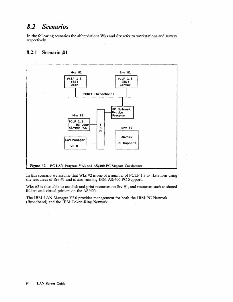
8.2 Scenarios In the following scenarios the abbreviations Wks and Srv refer to workstations and servers respectively.
8.2.1 Scenario #1
Hks #1
PCLP 1.3 PCLP 1.3 (BS) (BS) User Server
I PCNET (broacband) I 1
~ PC Network r-- Bridge
Hks #2 Program
PCLP 1.3 BS User - T
AS/400 PCS R Srv #2 N
AS/400 LAN Manager
PC Support V2.0 I -
Figure 37. PC LAN Program Vl.3 and AS/400 PC Support Coexistence
In this scenario we assume that Wks #2 is one of a number of PCLP 1.3 workstations using the resources of Srv #1 and is also running IBM AS/400 PC Support.
Wks #2 is thus able to use disk and print resources on Srv # 1, and resources such as shared folders and virtual printers on the AS/400.
The IBM LAN Manager V2.0 provides management for both the IBM PC Network (Broadband) and the IBM Token-Ring Network.
94 LAN Server Guide

8.2.2 Scenario #2
Hks 1H
PCLP 1.3 - PCLP 1.3 (BS) ~ (BS) User User
Srv #1
Hks #2 PCLP 1.3 I-- BS Server
PClP 1.3 T AS/400 PCS (BS) roo- R User N
Srv #2
AS/400
LAN Manager PC Support Ver 1.0 or
Ver 2.0 -
Figure 38. PC LAN Program VI.3 and AS/400 PC Support Coexistence
In this scenario we as~ume that Srv #1 is running hoth IBM AS/400 PC Support and as a PCLP 1.3 Base Services server.
Workstations on the LAN running as PCLP 1.3 users will now have access to both personal computer resources on Srv #1 and AS/400 resources without being aware of where they reside.
The IBM LAN Manager Vl.O and later, provides management for the LAN.
Coexistence 95

8.2.3 Scenario #3
Hks #1 Hks #3
PCLP 1.3 - PCLP 1.3 BS User BS User
ECF Req. ECF Req.
Srv #1
Hks #2 PCLP 1.3 - (BS)
PCLP 1.3 T Server BS User r--- R
ECF Req. N Srv #2
S/370
TSO/E and CMS LAN Manager Servers Ver 1.0 or
Ver 2.0 "---
Figure 39. PC LAN Program VI.3 and ECF Coexistence
In this scenario we assume that Wks # 1, Wks #2 and Wks #3 are running both the ECF requesters and as a PCLP 1.3 Base Services Redirector.
These workstations will have access to personal computer resources on Srv #1 and IBM System/370 host resources on Srv #2. Due to personal computer memory constraints Wks # 1 will have to use the ECF command interface for data base services.
The IBM LAN Manager Vl.O and later provides management for the LAN.
96 LAN Server Guide

8.2.4 Scenario #4
Hks #1
OS/2 Req.
OS/2 ECF
Hks #2
OS/2 Req.
OS/2 ECF
LAN Manager
Entry Vl.O
I / I
NetView R3
r--
I--
T - R
N
-
Figure 40. OS/2 Requester and ECF Coexistence
Hks #3
OS/2 Req.
OS/2 ECF
Srv #1
OS/2 LAN
Server
Srv #2
S/370
TSO/E and CMS Servers
. In this scenario we assume that ECF support is available under OS/2 (as per IBM's statement of direction) and that Wks #1, Wks #2 Wks #3 are running the OS/2 requester as one task and the OS/2 ECF requesters as another task.
These workstations will have access to personal computer resources on Srv #1 and IBM System/370 host resources on Srv #2. There should be no personal computer memory constraints providing the workstations are appropriately configured.
The IBM LAN Manager Entry Vl.O (or any of the other stand-alone management applications) provides management for the LAN.
Coexistence 97

8.2.5 Scenario #5
k H s #1 r---
LAN Manager .ECF Req. f----- Ver 1.0 or - or - Ver 2.0
NFS Client T R Srv #1 N
S/370
RT/PC Internet - TSO/E and CMS Router Servers
-
IEEE 802.3
I I NFS Client NFS
3270 Ernul. Server
Hks #2 Srv #2
Figure 41. ECF and NFS Coexistence
In this scenario we assume a mixed IBM/OEM environment. We also assume that the gateway is a PC/RT running the internet router and that all the workstations are personal computer DOS-based.
Workstations that are able to run NFS client protocols will be able to access NFS resources residing on both the IEEE 802.3 (Ethernet) LAN and the Token-Ring LAN. With the appropriate 3270 emulation support they will also be able to access 3270 applications running on the IBM System/370 host. By terminating the NFS client application and starting the ECF requesters, workstations attached to the IBM Token-Ring Network will have access to a different set of resources.
The IBM LAN Manager Vl.O or later provides management tor the IBM Token-Ring Network.
98 LAN Server Guide

8.2.6 Scenario #6
Hks #1 , Srv #1
PCLP 1.3 r-- PCLP 1.3 (BS) (BS) User Server
Hks #2 Srv #2
PCLP 1.3 (XS) t- PCLP 1.3 User ~ (XS)
Server Hks #3
Srv #3 OS/2 Req.
OS/2 LAN
Hks #4 Server
AS/400 PC Support ~ Srv #4 Requester
Hks #5 AS/400 T ~
ECF R PC Support N
Requester
Hks #6 Srv #5
I S/370 NFS Client -
Enhanced Connectivi ty
Hks #7 Facilities
FBSS 2.1 -- Srv #6
Horkstation
~ NFS
Server
LAN Manager Srv #7 Ver 1.0 or
Ver 2.0 fBSS 2.1
"-- Server
Figure 42. Coexistence of all IBM Server Implementations
In this scenario we assume that Wks # I is one of a number of workstations using the resources of Srv # I, Wks #2 is one of a number of workstations using resources on Srv #2, through to \Vks #7 being one of a number of workstations using the resources of Srv #7.
All of the workstations are able to coexist without interfering with one another and the IBM LAN Manager Vl.O or later will collect status and error information relating to the operation of the LAN.
Coexistence 99

100 LAN Server Guide

9.0 Design Considerations
9.1 General Aspects of LAN Design There are a number of general design considerations that should be borne in mind when implementing a LAN. These include:
• Performance, both in terms of the ability to move the required volume of data and still achieve the desired response times, and reliability in so far as the LAN should always be available during the scheduled hours of operation.
• Ease of installation and maintainability. The degree to which specialized tools and skills are required to install and grow the LAN, and the ability to add and remove workstations without disrupting the operation of the network.
• Manageability, being the ability to ascertain that a problem has occurred, determine the cause of the problem and take corrective steps, all within a reasonable period of time.
This chapter does not intend to provide an in-depth tutvrial on these topics, but rather to look at specific factors which relate to the selection of the most appropriate LAN configuration to meet your organizational requirements.
9.2 Particular Aspects of Designing the Server-Requester Relationship in a LAN Environment The characteristics of the enterprise have a strong bearing on the design of the LAN and may also influence the selection of a LAN server.
An enterprise with few people, all located within the same building and possibly on th~ same floor will have a relatively simple task of designing, installing, maintaining and managing their LAN.
Enterprises with many more people, located on multiple floors of a building and having a need to be connected to the LAN, will have to consider factors such as:
• The number of workstations that can attach to the LAN, and
• The possibility of installing more than one LAN and then interconnecting them to form a larger LAN.
Where the people are spread over a number of buildings within a campus, the LAN designer will need to consider:
• The ability of a single LAN to support great enough distances in order to span more than one building, or
• The possibility of interconnecting multiple LANs across distances which are exposed to the elements.
Design 101

Enterprises that have branches located in towns or cities across the country and that wish to install LAN s in all locations will need to be aware of:
• The possibility of interconnecting multiple LANs using PTT -provided communication facilities, and
• The type of communication facilities provided by the PTT and the speeds at which they operate.
A factor that affects all size enterprises is whether or not they have existing equipment to which workstations on the LAN must have access. Here the. considerations are:
• The availability of equipment that will provide gateway services for connecting LANs to networks of a different kind, and
• For those enterprises with branches in many locations, the possible use of an already installed network.
In any of the above situations the type of transactions being performed will affect decisions as to response time requirements, reliability of the network and backup capabilities. Transactions that are workstation-oriented and only require an occasional interactid'n with the server will impose different requirements from those, some of which can be found in the banking environment, that are highly visible and may have a direct effect on the enterprises profitability.
Volume of data transmitted is always a consideration but is especially so for enterprises which need to use PTT -provided facilities for communication between different locations.
9.2.1 Gateway Selection
In those situations where the server resides in a different network it may be necessary to use the services of a gateway in order to gain access to the server's resources. Typically gateways transform the link-level protocols of one network type to those of another while passing the higher level, communications protocols unchanged. They are able to provide access to networks in the same location or alternatively to networks in a remote location. In the latter case they use wide area network (WAN) communication facilities for providing connectivity. Gateways usually consist of hardware and either microcode or software or both.
Th e criteria for selecting a particular gateway include:
• Type of LAN supported - Token-Ring, Ethernet, or possibly a particular protocol
• Cost - the cost of the gateway controller related to the function and performance required
• Availability - a communications controller will typically be more reliable than a personal computer
• Network Management - the network management products and facilities that are available to manage the network
• Capacity to support devices - that is, the number of workstations to which the gateway is able to provide concurrent gateway services
• Performance - the volume of traffic that can be supported and the contrihution to transaction response times. Generally this is a function of hardware performance (internal cycle time) and the speed of the communications link supported, the latter being a significant factor.
IBM supplies gateways to meet a number of different requirements. Those that are relevant to this document are listed below. Many implementation examples have been provided in the preceding chapters and therefore are not included here.
102 LAN Server Guide
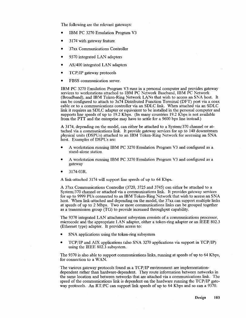
The following are the relevant gateways:
• IBM PC 3270 Emulation Program V3
• 3174 with gateway feature
• 37xx Communications Controller
• 9370 integrated LAN adapters
• AS/400 integrated LAN adapters
• TCP lIP gateway protocols
• FBSS communication server.
IBM PC 3270 Emulation Program V3 runs in a personal computer and provides gateway services to workstations attached to IBM PC Network Baseband, IBM PC Network (Broadband), and IBM Token-Ring Network LANs that wish to access an SNA host. It can be configured to attach to 3x74 Distributed Function Terminal (DFT) port via a coax cable or to a communications controller via an SDLC link. When attached via an -SDLC link it requires an SDLC adapter or equivalent to be installed in the personal computer and supports line speeds of up to 19.2 Kbps. (In many countries 19.2 Kbps is not available from the PTT and the enterprise may have to settle for a 9600 bps line instead.)
A 3174, depending on the model, can either be attached to a System/370 channel or attached via a communications link. It provide gateway services for up to 140 downstream physical units (DSPUs) attached to an IBM Token-Ring Network for accessing an SNA host. Examples of DSPU s are:
• A workstation running IBM PC 3270 Emulation Program V3 and configured as a stand-alone station
• A workstation running IBM PC 3270 Emulation Program V3 and configured as a gateway
• 3174-03R.
A link-attached 3174 will support line speeds of up to 64 Kbps.
A 37xx Communications Controller (3720, 3725 and 3745) can either be attached to a System/370 channel or attached via a communications link. It provides gateway services for up to 9999 PUs connected to an IBM Token-Ring Network that wish to access an SNA host. When link-attached and depending on the model, the 37xx can support multiple links at speeds of up to 2 Mbps. Two or more communications links can be grouped together as a transmission group (TG) to provide increased throughput capability.
The 9370 integrated LAN attachment subsystem consists of a communications processor, microcode and the appropriate LAN adapter, either a token-ring adapter or an IEEE 802.3 (Ethernet type) adapter. It provides access to:
• SNA applications using the token-ring subsystem
• TCP lIP and AIX applications (also SNA 3270 applications via support in TCP lIP) using the IEEE 802.3 subsystem.
The 9370 is also able to support communications links, running at speeds of up to 64 Kbps, for connection to a WAN.
The various gateway protocols found ill a TCP lIP environment are implementationdependent rather than hardware-dependent. They route infonnation between networks in the same location and between networks that are attached via a communications link. The speed of the communications link is dependent on the hardware running the TCP lIP gateway protocols. An RTIPC can support link speeds of up to 64 Kbps and so can a 9370.
Design 103

The FBSS communications server provides host access for FBSS workstations running on either an IBM PC Network Baseband, an IBM PC Network (Broadband), or an IBM Token-Ring Network. It provides access to either SNA or native X.2S applications over a communications link. The communications link can run at speeds of up to 9600 bps.
9.2.2 Bridges
An individual LAN, when connected to another LAN via a bridge, is referred to as a LAN segment. Bridges provide one possibility for interconnecting multiple LAN segments to form a single larger LAN. The terms LAN and LAN segment are used interchangeably depending on context.
LAN s that are bridged are considered to be in the same "address space." This means that workstations on one LAN segment are able to access resources residing on a second LAN segment and the fact that they are on a different LAN segments is transparent to them. There are a number of reasons for bridging LAN s. Those that are relevant to this dis-cussion are listed below: .
• Bridges allow different type LAN segments to be interconnected. For example it is possible to connect an IBM PC Network (Broadband) to an IBM Token-Ring Network.
• They facilitate the interconnection of different speed LANs, for example, the interconnection of a 4 Mbps Token-Ring LAN to a 16 Mbps Token-Ring LAN.
• They provide a means of extending the LAN configuration by either increasing the geographic area covered or by increasing the number of stations that can be attached, or both. Most LANs have a limit as to distances that can be covered and the number of stations that can be attached.
• More than one bridge can be used for interconnecting two LANs, thus providing an alternative connectivity path for session traffic.
• Large LANs can be split into smaller LANs to provide autonomous network management entities.
The possibilities for using bridges in a LAN design are governed to a certain extent by the type of LAN being implemented. This is because different LAN types require different bridging architectures, namely source routing, as used in the IBM Token-Ring Network and transparent bridging, as proposed for CSMAjCD-type LANs.
An important difference between these architectures is that with transparent bridging it is neither possible to have concurrently active parallel bridges (bridges spanning the same two LAN s) nor is it possible to have concurrently active parallel routes (routes that join the same source and destination using different physical paths), while with source routing bot1-are possible.
IBM supplies three bridge products, all of which run in a dedicated personal computer:
• The IBM PC Network Bridge Program - for interconnecting the IBM PC Network (Broadband) to a 4 Mbps Token-Ring LAN.
• The IBM Token-Ring Network Bridge Program V2.0 - for interconnecting TokenRing LAN s operating at either 4 Mbps or 16 Mbps.
• The IBM Token-Ring Network Bridge Program V2.l - also referred to as a remote bridge. It provides all the capabilities of IBM Token-Ring Network Bridge Program V2.0 plus the ability to interconnect remote token-ring LANs (4 Mbps or 16 Mbps) over a leased teleprocessing line running at speeds of between 9600 bps and T 1.
The following examples are based on the IBM Token-Ring Network:
104 LAN Server Guide

1. Figure 43 on page 105 shows a possible configuration for a three-story building. Each floor has its own LAN segment (referred to as a LAN in this example) which is connected via a bridge to two backbone LANs running up the length of the building. The server is attached to LAN 3 and is accessible by all workstations on all LAN s. Workstation X on LAN 1 has a number of route alternatives for accessing the server located on LAN 3. The most obvious two are:
• Route 1: X - > LAN 1 - > bridge 1 - > backbone LAN 1 - > bridge 5 - > LAN 3 - > server
• Route 2: X - > LAN 1 - > bridge 2 - > backbone LAN 2 - > bridge 6 - > LAN 3 - > server.
Route 2 can be a "backup" route for route 1 and visa versa.
B LAN 1 B a a c c k k b b 0 0
n LAN 2 n e e
t. L A A N N
LAN 3 1 2
IBll = Bridge 1
Figure 43. A bridged LAN Showing Alternate Session Paths
2. Figure 44 on page 106 shows three geographically distributed TRNs (Token-Ring. Network LANs) connected to one another via remote bridges and leased communication lines. TRN 3 supports the server function running in an IBM System/370 host which is attached to the LAN via a gateway. In this example workstation X on TRN 1 has two route possibilities for accessing the server:
• Route 1: X - > TRN 1 - > remote bridge 1 - > leased line - > remote bridge 2 - > TRN 3 - > GW - > host
• Route 2: X - > TRN 1 - > remote bridge 5 - > leased line - > remote bridge 6 - > TRN 2 - > remote bridge 4 - > leased line - > remote bridge 3 - > TRN 3- > GW - > host.
Route 2 can be an alternative route for route 1 and visa versa. An interesting feature of this configuration is that it provides alternate routing for SNA boundary node traffic, a facility that was previously not available.
Design 105

x y
TRN 3
ISB11 = Split Bridge 1
~ = Gateway
Figure 44. Bridging of Remote LANs Using Split B:-ic'be~
9.2.3 Location of Servers
The decision as to where to locate the server in a small LAN (LANs with less that 40 workstations are generally considered to be small) should not normally create any difficulties. These LANs usually consist of a single LAN segment to which the server or servers will be attached. Larger LAN s introduce a number of complexities and decisions need to be made based on:
• Geographic distribution and number of the users wishing to access the server
• Affinity groups
• Which server implementation has been selected
• Cost of the server implementation
• Volume of traffic between the requesters and the server
• Skills of the end users.
These factors are generally all interrelated but for purposes of simplicity are discussed individually.
The geographic distribution and number of the users wishing to access the server has been dealt with to some extent in "Particular Aspects of Designing the Server-Requester Relationship in a LAN Environment" on page 101. This will determine the size of the LAN or LAN s, the number of LAN segments and the location of the LAN segments. When remote LAN segments are interconnected the decision might be to implement more than one server, locate them on the individual LAN segments, and use the interconnection for casual communication.
106 LAN Server Guide

AffInity groups are groups of end users who perform related tasks. Information studies have shown that a high percentage of all communication generated by members of an affinity group will be to other members of the same affinity group. For this reason it is generally
, desirable that all members of an affmity group are attached to the same LAN segment.
The server implementation that has been selected will typically have a bearing on where it is located. For example the granularity of a personal computer-based implementation may make it practical to implement one or more servers per affInity group. On the other hand a System/370-based server may mean that there will be one server computer for the entire enterprise. In this case it would probably be attached to the backbone network in an attempt to equalize the session path for all users.
The cost of the server implementation, when compared with the expected benefit and the number of users it must support will determine the number of server computers that are to be installed. This in tum will influence whether the servers are attached to the backbone LAN or to individual LAN segments.
The volume of traffic between the requesters and the server will affect the viability of remotely locating the server and providing access via a wide area network. When large volumes of traffic are involved it is desirable to directly attach the server to the LAN on which the requesters reside. Volume of traffic will, to a much lesser extent, have a bearing on the number of bridges that the session path should cross. A single bridge is generally only capable of carrying a percentage of the traffic that any LAN segment can carry.
End users with computer-related skills will generally welcome the challenge of maintaining their own server or servers. Users who do not have these same skills and who are not inclined to develop them would prefer that the IS department maintain their server. In the latter case the servers would be implemented where the IS department has access to them.
9.2.4 Analysis of the Current Environment and Customer Skills
The investment an enterprise has in existing equipment may, to a large extent, influence the decision as to which server the enterprise will select. For example an enterprise with an installed AS/400, wishing to install a LAN, may very well implement the AS/400 as their server, particularly if the system is not fully utilized. The same consideration would apply to ECF on a IBM System/370 host.
The above point is very closely related to the investment an enterprise has in skills. The System/370 type skills required to implement ECF may well exclude an enterprise which has previously only had personal computer-related experience from the benefits it has to offer. Under such circumstances a personal computer-based server implementation such as IBM PC LAN Program VI.3 or IBM OS/2 LAN Server VI.O, or both together could be very attractive.
An enterprise with multiple vendors equipment installed may fmd that NFS as a server is the only economic means of providing a server environment that is accessible by the different vendor's equipment.
Another key consideration is whether or not the enterprise has the programming skills necessary to develop applications in-house. For example an FBSS environment is heavily dependent on "home grown" applications and requires good skills in the communications area.
For enterprises that have no previous LAN experience, the challenges of implementing any type of LAN will be similar. The real test comes when problems are encountered. For this reason the availability of comprehensive management tools should be an important deciding factor.
Design 107

9.3 Pelfol"mance Factol"s The type or speed of the LAN will normally have very little impact on performance where only a few interactive stations are involved. However, for LANs consisting of many stations and where large volumes of data are being transmitted, particularly graphic data streams, the choice of LAN s can be critical.
The important consideration when comparing different LAN s is the data throughput capability. This very often has no relationship to the actual media speed and can be referred to as an efficiency factor. For example a LAN delivering a data throughput of 400 Kbps on a I Mbps LAN can be considered as having an efficiency factor of 0.4 (40 percent). Elements that determine the efficiency factor are: architecture - LANs based on token-ring network architecture deliver far higher throughput capabilities than their CSMA/CD counterparts, and, to a much lesser extent, the way in which the LAN is used as outlined below:
• Every frame transferred across the LAN has a header and a trailer appended. These are independent of the amount of data being sent and r~present an overhead. Thus transferring fewer large blocks of data across the network is more efficient than transferring many smaller records.
• The size of the frame transmitted and received also impacts the amount of work that the LAN adapter must perform. Each frame sent incurs basically the same overhead of frame setup, routing and error checking.
• Protocol overhead associated with the communication between server and requester may also have an impact on performance. Implementations based on a datagram type service generally have less communications overhead than implementations based on a connection-oriented service but at the expense of integrity. For unreliable networks the overhead of recovery in terms of additional transmissions may outweigh the bene-fits of not providing acknowledgements. SNA is typically a connection-oriented protocolwhile the User Datagram Protocol (UDP) of TCP/IP is, as the name implies, a datagram service.
The next sections deal with practical performance considerations for designing LAN s.
9.3.1 Overhead of Crossing Several Segments
Bridges provide solutions for a number of diverse requirements as discussed in "Bridges" on page 104, in that they allow for a great deal of configuration flexibility. However, there are a couple of considerations that should be borne in mind when designing a bridged LAN:
1. Every bridge crossed in the session path introduces a bridge hop delay. This is normally insignificant, as it can be counted in milliseconds, but may have an impact on perceived response times when multiple bridges are crossed and the session path becomes heavily utilized.
2. In those environments where parallel bridges are supported (that is, source routing is used), the session path is determined at session setup time and is retained for the duration of the session. The route selected at that time delivers the best response times but as traffic increases this may no longer be true. Source routing will only provide load balancing in environments where sessions are established and terminated fre.; quently, and not in those environments where sessions are established before traffic starts and held for the entire day. For example a 3l74-03R will establish its route when powered on and before users log on to their terminals.
Thus, in bridged environments where more than three LAN s are involved and there is a substantial amount of inter-LAN traffic, a backbone concept as shown in Figure 43 on page 105 may deliver better response times than a daisy-chain configuration. This is because in such a configuration the session path should never have to cross more than two bridges in anyone direction (sending or receiving). An improvement on this configuration
108 LAN Server Guide

would be to attach the server to the backbone LAN in which case the session path would only have to cross one bridge in anyone direction.
The bridge programs run in dedicated personal computers. By upgrading the personal computer model, throughput can be improved. Be aware though, that upgrading beyond a PS/2 model 50 may not give the desired result.
The primary consideration for implementing parallel bridges should be to provide a backup route and not for the provisien of load balancing, although the latter may be a contributing factor.
9.3.2 Overhead Created by Heavily Utilized Paths
Every component within a network 'has a minimum time in which it can perform certain tasks. This is due to the characteristics of the component and can be referred to as the service time. For example, if we assume that 100 percent efficiency is possible then a 9600 bps communications line is able to transport 9600 bits in one second, and therefore the service time for 9600 bits over such a line is one second.
The line, in this context, is referred to as a "server" and will continue to transmit approximately 9600 bits every second. However, a fullscreen output message which may exceed 1200 characters (9600 bits) but which we will consider as being 1200 characters, may arrive at the "server" behind other traffic. The time taken for the message to get to the other side of the line is now the total of service time plus queuing time. We refer to this as total service time. The arrival rate of traffic at a server is not always constant and is therefore averaged and referred to as a utilization percentage.
A rule of thumb for determining total service time is to apply the simplified queuing formula contained in Figure 45 on page 109. For example, if we assume that the line is 50 percent utilized then we can calculate that the total ser,Tlce time will be two seconds for the same 1200 characters.
Two seconds is thus the contribution that the line, as one of the components in a session path, will make to a transaction's response time. We can see from the formula that as the utilization of a component (the line in this example) increases so the total service time increases at an exponential rate. This factor is particularly relevant when selecting a linkattached gateway.
ST TS =
1 - % utilization
TS = Total Service Time
ST = Service Time
Figure 45. Simplified Queuing Formula for a Single Server
Note: This formula is totally invalid for computations that involve components, such as a 37xx communications controller, which incorporate multiple "servers."
Design 109

9.3.3 Performance Degradation ofa Low Performing Component
Two situations are considered in this section:
1. The implementation of a link-attached 3174 as a gateway
2. The impact of implementing a low-speed communications between remote bridges.
The 3174 models 51R, 01R, 52R, and 02R are link-attached to thehost and provide gateway services to DSPUs (refer to '~Gateway Selection" on page 102 for examples of DSPUs) attached to a LAN. The 3174, together with the DSPU s that use its services, is viewed by the host as a multipoint configuration. This means that although the user derives the benefit of line speeds up to 64 Kbps and excellent processor perfonnance, he or she should be aware of the polling overhead associated with such a configuration. Every DSPU is individually polled by the upstream communications controller. In this environment polling can be considered a non-productive overhead which limits the number of DSPUs that should be configured when good host response times are required. In LANswhere IBM PC 3270 Emulation Program V3 is used, a configuration as shown in Figure 46 on page 110 will reduce the impact of polling. One of the workstations i~ configured as a gateway and will be polled. It then provides gateway services to up to 32 workstations configured as network stations. The latter are not polled. The IBM PC 3270 Emulation Program V3 gateway in tum uses the 3174 as its gateway.
LAN Workstation Connection Gateway
Host Connection Host Environment
<----> <:-----> <----> <:----> <------->
r----............. . 3270EM Network station
B = Modem
Token-Ring
3270EM Gateway
3270 r- V Application N T C A p M
'--
Figure 46. A possible Solution for Reducing Remote 3174 Polling Overhead
A 37xx communications controller is not subject to the same polling considerations as a 3174 gateway environment. The gateway 37xx is polled as a single physical unit (PU) by the upstream communications controller and, in contrast to the normal SDLC poll which can be referred to as an activity poll, PUs downstream of a 37xx gateway receive an HDLC inactivity (timeout) poll on a far less frequent basis. This has no noticeable effect on performance.
In a bridged LAN environment, one of the factors to consider is the use of buffers in the bridge. \Vhere high inter-LAN traffic volumes are involved it is possible the bridge may suffer from buffer depletion. This is because the bridge is unable to pass on traffic as fast as it is receiving it. The remote bridge LAN environment as shown in Figure 47 on page 111 is potentially susceptible to this situation. The potential exists in that the speed of the communications link between the remote bridge personal computers may not be adequate for the volume of inter-LAN traffic. Under these circumstances it is possible that frames
110 LA:\, Server Guide
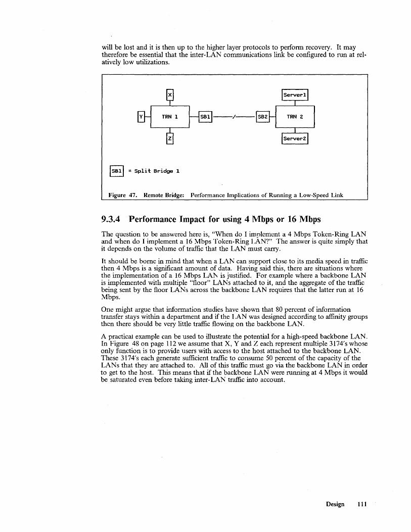
will be lost and it is then up to the higher layer protocols to perform recovery. It may therefore be essential that the inter-LAN communications link be configured to run at relatively low utilizations.
y TRN 1
ISBll = Split Bridge 1
Figure 47. Remote Bridge: Performance Implications of Running a Low-Speed Link
9.3.4 Performance Impact for using 4 Mbps or 16 Mbps
The question to be answered here is, "When do I implement a 4 Mbps Token-Ring LAN and when do I implement a 16 Mbps Token-Ring LAN?" The answer is quite simply that it depends on the volume of traffic that the LAN must carry.
It should be borne in mind that when a LAN can support close to its media speed in traffic then 4 Mbps is a significant amount of data. Having said this, there are situations where the implementation of a 16 Mbps LAN is justified. For example where a backbone LAN is implemented with multiple "floor" LAN s attached to it, and the aggregate of the traffic being sent by the floor LAN s across the backbone LAN requires that the latter run at 16 Mbps.
One might argue that information studies have shown that 80 percent of infonnation transfer stays within a department and if the LAN was designed according to affmity groups then there should be very little traffic flowing on the backbone LAN.
A practical example can be used to illustrate the potential for a high-speed backbone LAN. In Figure 48 on page 112 we assume that X, Y and Z each represent multiple 3174' s whose only function is to provide users with access to the host attached to the backbone LAN. These 3174' s each generate sufficient traffic to consume 50 percent of the capacity of the LANs that they are attached to. All of this traffic must go via the backbone LAN in order to get to the host. This means that if the backbone LAN were running at 4 Mbps it would be saturated even before taking inter-LAN traffic into account.
Design III

. [B1"1 = Bridge 1
B a c k b o n e
16
M b p s
TRN 1 - 4 Mbps
TRN 2 - 4 Mbps
Host
Figure 48. 16 Mbps Backbone Token-Ring Network
9.4 Interoperahility and the Future with SAA Current server implementations provide a high degree of function within a specific environment. However, although two implementations may both use the SRPI, this does not imply that the requester of one can access the server of the other. If this is the long-term objective,then one of the challenges facing product designers is the fact that data stored on one system is not necessarily in the same format as the same data stored on another system. This is largely a function of different operating systems. Generally speaking data is either stored in stream ftles, flat ftles or data-bases.
Stream flies provide only the minimum amount of support needed to access flie data and thus provide the greatest flexibility to the programmer. \Vhen used, strings of bytes can be read or written according to their relative position within the flie. Examples of stream flies are found in UNIX and personal computer DOS and OS/2.
Flat fIles are record flies that attempt to provide a broad set of functions that are useful in implementing flie models of high-level languages. Sequential access, direct access and indexed-sequential access flies are classifted as flat ftles with examples of such flie systems being VSAM under MVS/XA and the integrated flie system of OS/400.
Hierarchical and relational data bases are forms of record flies that have been designed with data integrity, recovery, security, access flexibility and performance in mind. An example of a relational data base is DB/2 under MVS.
Stream flies, flat flies and data bases each serve different requirements and one may be better suited to storing a particular type of data than the other. For example a flat flie is better suited to storing complex documents than a data base. The net result is that even with the emergence of the Database Manager under OS/2 it does not indicate a trend that there will be a move away from stream flies and flat flies. Programmers therefore require a framework for developing servers and requesters that will communicate between different environments and produce consistent results.
Systems Application Architecture (SAA) is a framework which provides cross-systems consistency across a broad spectrum of hardware, architecture, and operating systems en-
112 LA~ Server Guide

vironments. What this means in practical tenns is a common user interface, portability of applications and a consistent means of communication across the SAA designated environments, namely;
• MVS/ESA
• VM & VM/XA
• OS/400
• OS/2 EE.
These capabilities are defmed within three elements of SAA; Common User Access (CUA), Common Programming Interface (CPI) and Common Communications Support (CCS). See Figure 49 on page 113. CCS utilizes the SNA logical unit (LU) type 6.2 protocols and provides interconnect and data interchange to SAA end users and applications through the CPI, while also specifying the means by which non-SAA systems may participate in SAA environments.
ISAA Application I ISAA Application I CPI CPI
cIIFile I/oISQLI cIIFile I/oISQLI
LJ Support
D-EJ Support LJ Software Software
Figure 49. SAA: Showing the Relationships of CPI and CCS
Within the context of servers and requesters the element of SAA that is important in terms of future directions and development is the CPI. The two environments to be considered are;
• Distributed applications
• Distributed data.
Distributed applications require program-to-program communications in order for one SAA application to access and exchange data with another. The Communications Interface (CI) which is part of CPI, provides the means, at program execution time, of generating the appropriate CCS formats and protocols for communicating with another SAA application. The CPI/CI is destined to replace the SRPI, in an evolutionary manner, over time.
Distributed data may be stored, retrieved or updated either as fues or as a relational database with elements of CPI having been specified to support both environments. Files are accessed using the fue input/output element of CPI where requests are transfonned into the CCS protocols defmed in the IBM Distributed Data lVlanagement (DDM) architecture. The CPI element for a relational data base is IBM's Structured Query Language (SQL)
Design 113

114 LAN Server Guide

Acronyms and Abbreviations ANSI: American National Standards Institute
APPC: Application Program-to-Program Communication
ASCII: American (National) Standard Code for Information Exchange
A \VG: American Wire Gauge
BIOS: Basic Input/Output System
BNN: Boundary Network Node
bps: bits per second
BS: Base Services
CATV: Community Antenna Television (Cable TV)
CCITT: Comite Consultatif International Telegraphique et Telephonique (International Telegraph and Telephone
Consultative Committee)
CCS: Comnon Communications Support
CF: Control Field
CIM: Computer-Integrated Manufacturing
CPI: Common Programming Interface
CPRB: Connectivity Programming Request Block
CSMA/CD: Carrier Sense Multiple Access with Collision Detection
C&Sl\I: Communications & Systems Management
dB: decibel
DDM: Distributed Data Management
DIT: Distributed Function Terminal
DISC: Disconnect (Command)
DLC: Data Link Control
DOS: Disk Operating System
DSAP: Destination Service Access Point
DSPU: Downstream Physical Unit
DTE: Data Terminal Equipment
DW4: DisplayWrite 4
EBCDIC: Extended Binary Coded Decimal Interchange Code
FCS: Frame Check Sequence
FDX: Full-Duplex
FDDI: Fiber Distributed Data Interface
GV/-:'~CP: Gateway NCP
HDX: Half-Duplex
HLLAPI: High-Level Language Applica~ tion Programming Interface
ICS: IBM Cabling System
INN: Intermediate Network Node
IEEE: Institute of Electrical and Electronic Engineers
IMPL: Initial Microprogram Load
10: Input/Output
IPC: Inter Process Communication
IPL: Initial Program Load
ISO: International Standards Organization
IWS: Intelligent Workstation
KB: Kilobytes
Kbps: Kilobits per second (Thousands of bits per second)
LAN: Local Area Network
LED: Light Emitting Diode
Acronyms and Abbreviations lIS

LLC: Logical Link Control
LPDU: Logical Link Protocol Data Unit
LSAP: Logical Link Control Service Access Point
LSP: Local area network (LAN) Support Program
LU: Logical Unit
l\1AC: Medium Access Control
MAP: Manufacturing Automation Protocol
l\IAU: Multi-station Access Unit
l\1B: Megabytes
Mbps: Million bits per second
MFI: Main Frame Interactive
MMS: Manufacturing Messaging Specifications
MVID: Major Vector Identifier
NADN: Nearest Active Downstream Neighbor
NAUN: Nearest Active Upstream Neighbor
NCP: Network Control Program
NETBIOS: Network Basic Input/Output System
NTRI: NCP Token-Ring Interface
OEM: Other Equipment Manufacturer
OSI: Open Systems Interconnection
OS/2: Operating System/2
OS/2 EE: Operating System/2 Extended Edition
OS/2 SE: Operating System/2 Standard Edition
P ABX: Private Automatic Branch Exchange
PC: Personal Computer
PCLP: Personal Computer Local area network Program
116 LAN Server Guide
Pl\1: Presentation . Manager
PS/2: Personal System/2
PU: Physical Unit
RAM: Random Access Memory
RF: Radio Frequency
RI: Routing Information
RIPL: Remote Initial Program Load
ROM: Read-Only Memory
RPM: Records Per Minute
RR: Receive Ready
SAA: Systems Application Architecture
SAM: Sequential Access Method
SABME: Set Asynchronous Balanced Mode Extended (Command)
SAP: Service Access Point
SDLC: Synchronous Data Link Control
SNA: Systems Network Architecture
SPCS: Service Point Control Service
SRPI: Server/Requester Programming Interface
SSAP: Source Service Access Point
TCP /IP: Transmission Control Protocol/Internetwork Protocol
TIC: Token-Ring Interface Coupler
TRA: Token-Ring Adapter
TRl\1: Token-Ring Multiplexor
TRSS: Token-Ring Subsystem
TSAF: Transparent Services Access Facility
TIP: Telephone Twisted Pair (Wiring)
VA: Unnumbered Acknowledgment
VSAM: Virtual Storage Access Method
XID: Exchange Identification

A
Access to AS/400 data bases 43 ACF/VTAM 1, 59 Address Resolution Protocol 73 Address space 104 Administration and Control 29 Advanced Peer-to-Peer Networking 43, 47
Advanced Program-to-Program Communications 17, 43, 47, 66
Advanced Program-to-Program Communications/PC (APPC/PC) Release 1.11 24
Affmity groups 106 AIX 69 AIX/RT 70 AIX/R T NFS 69 AIX/370 70 AIX/370 NFS 69 Alert feature 29 Alias 27 Analysis of the current environment and customer skills 107
API 52 APPC 17,43,47,48, 56,66 APPC node 32 APPC support 32 APPC/PC 24 Application Programming Interface 52 Application Selector 12, 14 Application-level protocol 71 APPN 43, 47, 48 ARP 73 ASCII 52,58 ASCII host 16 ASCII hosts 17,32 ASCII text 45 Assigned shared folders 53 ASYNC Communications 32 Asynchronous 47 Asynchronous events 81 Asynchronous Terminal Emulation 32 AS/400 48 AS/400 integrated LAN adapters 102 ASj400 Office 44, 45 AS/400 PC Support 24,43
Basic Functions 43
Index Compatibility and Coexistence 51 Connectivity 47 Interfaces 52 Management 54 National Language Support 52 Operating Environment 46 Overvjew 43 PC Support/36 55 Perfonnance Considerations 53 Security 53
AS/400 Token-Ring Support 8 Audit trail 29 Availability 102 A vaila bility of equipment 101
B
BACKUP 84 Base Expander 2 Base requirements 6 Base Services 11, 16, 25, 26, 51, 65 Baseband Extender 2 BASIC random 45 BASIC sequential 45 Batch functions 6 Bridge hop delay 108 Bridges . 104 BSC 47 Buffer depletion 110 BUS topology 2
c Capacity planning theory 6 Capacity to support devices 102 Carrier Sense Multiple Access with Colli-sion Detection 2
CCS 112 Channel speeds 5 Characteristics of the enterprise 101 CI 112 Clerical workers 6 Client function 69 Client Protocols 78 CMS 57
Index 117

Coexistence 93 Coexistence Enhancement Feature 47, 51 Common Communications Support 112 Common denominator 6 Common Programming Interface 112 Common User Access 112 Communication between LAN s 81 Communication facilities 101 Communication Servers 83 Communications and System Management 7
Communications and Systems Manage-ment 41
Communications Interface 112 Communications Manager 30,32 Compatibility and Co-existence 24, 65 Compatibility and Coexistence 51 Complex data structures 71 Connection Authentication 79 Connection oriented 4, 108 Connectivity 16, 30, 47, 61, 73, 85 Connectivity for LAN attached Work-stations 61
Conversations 53 Coresidence with IBM PC LAN Program V1.3 43
Cost of server 106 Cost of the gateway 102 CPI 112 CPI/CI 112 Creative functions 6 CSMA/CD 2,8 CSV 58 CUA 112 Customization Utility 84 Cycle time 5 C&SM 7,41
D
DARPA 73 Data access protection 11 Data base fues 45 Data Base Services 58 Data Export Security 7Cy Data Import Security 79 Data Transfer 45 Data transfer between a personal computer and the AS/400 43
Datagram 4, 108 DBCS 52 DBCS. 40 DB2 57,58 DDM 45,112
118 LAN Server Guide
Dedicated directories 82 Defense Advanced Research Projects As-sociation 73
Design Considerations 101 DFT 102 DIAL VTAM 77 DIF 45, 58 Direct 5 Direct access 82 Direct access fues 112 Disk seek time 5 Display emulation 48 Distributed Data Management 45, 112 Distributed fues 81 Distributed Function Terminal 102 Distributed processing systems 81 DL/I 57,58 Domain 12, 13,27 Domain Controller 13, 24, 27 DOS 14 DOS random 45 Driver for the Monochrome Display 83 DSPU 102, 110 DXT 58
E
Ease of installation 101 Ease of use factors 4 EBCDIC 52,58 ECF 43,57 Efficiency 108 EGP 73 End User Interface 25, 52, 66 End-User Interface 39 Enhanced Connectivity Facilities V 1.1 57
Basic Functions 57 Compatibility and Co-existence 65 Connectivity 61 Interfaces h5 Management 67 Operating Environment 59 Overview 57 Performance Considerations 67 Security 67
Entry Point 7 Error log 29 Ethernet 2, 73 EXEC 2 (VM only) 66 Extended Services 11, 12, 16, 25, 26 Exterior Gateway Protocol 73 External Data Representation 69, 70, 71,
78 External resources 13

F
Fast Path 58 FBSS 81 FBSS Communication Server 102 FBSS-servers 81 Field-level transformations 58 File organization 5 File sets 12 File sharing 11, 43 File Transfer 58 File transfer capabilities 57 File Transfer Protocol 71 Filesets 14 Financial Branch System Integrator 91 Financial Branch System Services V2.1.1 81
Basic Functions 81 Connectivity 85 Financial Branch System Integrator 91
Management 92 Operating Environment 84 Overview 81
Financial I/O Servers 83 Flat fues 112 Fly lead 2 Focal Point 7, 54 Folder paths 44 Frame 4 Frame header 108 Frame trailer 108 FTP 71 Functional Equivalence 78
G
gateway 17, 73 Gateway Selection 102 Gateway station 17 Gateway support 43 General Aspects of LAN Design 101 Geographic location 106
H
HDLC 83,87 HDLC poll 110 Hierarchical databases 112 Home flieset 14 Host Connectivity 32, 48, 87 Host system tasks 45
I
IBM AS/400 PC Support 43 IBM C 66 IBM CMS Servers 57 IBM Enhanced Connectivity Facilities Vl.l 57
IBM LAN Manager Entry Vl.O 8 IBM LAN Manager Vl.O 8 IBM LAN Manager V2.0 8 IBM LAN Support Program 24, 26, 86 IBM Macro Assembler 66 IBM NetView Distribution Manager 10 IBM OS/2 LAN Server Vl.O 10, 24, 27 IBM OS/2 Presentation Manager 28,39 IBM Pascal 66 IBM PC LAN Program V1.2 24 IBM PC LAN Program V1.3 10, 11, 27, 51,65
IBM PC LAN Program V1.3 re"questers 39
IBM PC Network Baseband 2,8, 16,61, 86
IBM PC Network Bridge Program 104 IBM PC Network (Broadband) 2,8, 16, 61, 86
IBM PC 3270 Emulation LAN Management Program V1.0 8
IBM PC: 3270 Emulation Program V3 1, 17, 59, 61, 102, 110
IBM" Personal Computer Distributed Systems Node Executive 54
IBM Token-Ring Network 2, 8, 16, 61, 86, 102
IBM Token-Ring Network Bridge Program V2.0 104
IBM Token-Ring Network Bridge Program V2.1 104
IBM Token-Ring Network Trace and Per-formance Facilities 8
IBM TSO/E Servers 57 IBM 3270 PC fue transfer 58 IBM 3270 Workstation Program V1.1 17, 59,61
IEEE 802.2 16, 24, 30, 71 IEEE 802.3 2, 73, 102 Index sequential 5 Index-sequential access flies 112 Indexed sequential access 82 Input/output 6 Intelligent query facility 4 Interactive functions 6 Internal resources 13 Internet address 73 Internet Protocol 71, 73 Internet Router 73 Interoperability and the future with SAA 112
Investment in equipment 107 Investment in skills 107
Index 119

INZPCS 52 IP 71,73 IP datagrams 73 IP header 79 IS Department 106 I/O 6
J
Job categories 6
L
LAN Administration 10 LAN Administrator 29 LAN Components 2 LAN Connectivity 16, 30, 47, 86 LAN distances 101 LAN Error Monitor 8 LAN Management 8 LAN Print Manager 24 LAN segment 8 LAN segments 104 LANMSG 14 LEM 8 Local sessions 87 Location of Servers 106 Logical data base ft.Ies 45 Logical networks 73 LOGOFF 14
M
Machine Type Independence 70 Machine-Readable Information 52 Machine-Type independence 69 Magnetic Stripe Reader Server 83 Maintainability 1 U 1 Manageability 101 Management 7,26,41,54,67,92 Managerial staff 6 Media speed 5 Medialess devices 28 Medialess workstations 11 Message Function 44 Messaging 11 Messenger II Modified PC Support/36 router 56 Modified System/36 router 53 MRI 52 MSAU 2 Multistation Access Unit 2
120 LAN Server Guide
N
National Language Support 25,40,52, 66
Native X.25 Server 83, 87 NETCOPY 39 NET MOVE 39 NET PERMIT 24 NET RUN 28,39 NET SHARE 11, 12 NET USE 11 NETBIOS 16,24,30,86 Netname 27 NetView 7,41 Net View Access Services 67 NetView Distribution Manager 26, 84 NetView DM 10 NetView/PC 7,67 Network File System 69
Basic Functions 69 Connectivity 73 Functional Equivalence 78 Operating Environment 72 Overview 69 Performance Considerations 79 Security 79
Network management 102 Network station 17 NFS 3.7 69 No 'conversion 45 Non-owner workstations 81 Number of Users Supported 55 Number of workstations 101
o
Office integration 43 Online reference information 14 ONMA 7 Open Network Management Architecture 7
Operator Interface 83 Organizer 43, 45 OS/2 EE 30 OS/2 Extended Edition Vl.l 27 OS/2 EZ-VU 39 OS/2 LAN Server Vl.O 27
APPC 27 Basic Functions 27 Compatibility and Co-existence 39 Connectivity 30 IBM OS/2 Communications Manager 27
Interfaces 39 Management 41 NETBIOS 27 Operating Environment 29 Overview 27

Perfonnance Considerations 41 Security Services 40 3270 protocols 27
OS/2 requester 25,27, 28 Overhead created by heavily utilized paths 109
Overhead of Crossing several segments 108
p
Packet-switched technology 71 Parallel bridges 104, 108 Parallel routes 104 Particular Aspects of Designing the ServerRequester relationship in a LAN Environment 101
PASSTHRU 77 PC LAN Program V1.3 11
Basic Functions 11 Compatibility and Co-existence 24 Connectivity 16 Interfaces 25 Management 26 Operating Environment 15 Overview 11 Performance Considerations 26 Security Considerations 26
PC Network Analysis Program 8 PC Requester 65 PC Support menu 44 PC Support Organizer 43 PC Support Organizer menu 44 PC Support Update Function 54 PC Support/36 47, 51, 55 PC Support/36 Release 5 Modification
1 24 PC Text Assist 45 PC 3270 Emulation Program Version 3.04 24
PCLP 14 PCLP 1.3 11 PCSUPDT 54 PC/DSNX 54 PC/Integrator 91 peer-to-peer 32 Perfonnance 4, 101, 102 Performance Considerations 26, 41. 53. 67, 79
Performance degradation of a low performing component 110
Performance Factors 108 Perfonnance Impact for using 4 Mbps or
16 Mbps 111 Performance statistics 29 Personal Services/PC 65 Physical data base flies 45 Physical networks 73 Physical-level protocol 71
PIN Pad Device Server 83 Print flies 14 Print priorities 28 Print queue management 11 Print sharing 43 Print spooler 28 Printer defmitions 14 Printer emulation 48 Printer Management 28 Printer Servers 83 Printer sharing 11 Private applications 14 Professionals 6 proftle options 45 PROFS/PC 65 Program Code 52 Program Server 12, 14 Program-to-program communications 81 Programming Interfaces 52, 66 Protocol overhead 4 PRPQ 51 PTT 101 Public directories 82
Q
Query facility 4 QueLin; formula 109
R
RACF 67 Random flie access 5 Random processing 5 RCMS 84 Receiver 11, 12 Record flies 112 Redirector 11, 12, 24, 65 Relational databases 112 REM 8 Remote bridge 104, 110 Remote Change Management Services 84 Remote Initial Program Load 28 Remote Initial Program Load (RIPL) Workstations 12, 14
Remote IPL 10 Remote Procedure Call 69, 70, 78 Remote Program Execution 28 Request types 5 Requester 13 Requesters 1, 27 Requesters/Servers 57 Resource Sharing 27 RESTORE 84 REXX (VM only) 66 Rights 53 Ring Error Monitor 8, 54
Index 121

Ring topology 2 RIP 73 RIPL 10, 14, 26, 28, 41, 91 RIPL Workstation 14 Router 43, 51, 56 Router function 1 router program 32 Routers 59 Routing Infonnation Protocol 73 RPC 70,71 Run DOS commands 43, 44 Run Host Commands 59
s SAA 112 SAM 58 SBCS 40 Screen Design Aid 45 SDA 45 SDF Delimited Fonnat 58 SDLC 47,83,84,87 SDLC poll 110 Seamless environment 43, 52 Secretarial staff 6 Security 53, 67, 79 Security Considerations 26 Security Services 40 Selected server 106 Send and receive messages 43 Sequential 5 Sequential access 82 Sequential access flies 112 Sequential processing 5 Serial line protocols 73 Serially attached devices 27 Server 12, 109 Server Capacity 5 Server function 69 Server Implementation 4 Server name 27 Server Operation 1 Server owners 81 Server Protocols 78 Server-Requester Programming
Interface 1, 57, 59, 61, 81 Server-requesters pair 57 Servers 1, 11,27 Service Point 7 Service requests 6 Service time 109 Session 45 Session pairs 86 Session path 108 Shared applications 14 Shared DOS Directory Support 82 Shared File Server 82 Shared flies 81 Shared fmance I/O devices 81
122 LAN Server Guide
Shared Folders 44, 55 Size of frame transmitted 108 Sizing the Server 6 Skills of the end users 106 SNA 4, 102, 108 SNA device emulation 48 SNA Network Link 76 SNA Server 83, 87 SNALINK 76 Source routing 104, 108 Speed of the LAN 108 Spirit of the International LAN Standards 93
Split bridge 104, 110 Splitter 2 SQL 58, 112 SQL/DS 57,58 SRPI 1, 57, 59, 61, 66, 81, 112 Stand-alone Station 17 Standalone Station 102 Stateless flie service 70 Stream flies· 112 Structured Query Language 112 Supervisor-router program 81 SYLK 58 System Administrator 13, 26 System date and time 14 Systems Application Architecture 112 System/36 48 Sy~te~."70 Assembler 66 System/370 host 16 System/370 Host Connectivity 17, 77 System/370 hosts 32
T
TCP 71,73 TCP header 79 TCP/IP 4, 69, 70, 71, 73, 108 Tep /IP Connectivity 73 TCP /IP for VM NFS 69 TCP /IP Gateway Protocols 102 TELNET 71, 77 Telnet Protocol 71 Terminator plug 2 TFTP 71 Think time 6 Throughput capability 5 Token Passing 2 Token-Ring Network 8 Token-Ring Networks 73 Total service time 109 Trace Facilities 83 Tranceiver 2 Transfer Function API 52 Translator Unit 2 Transmission Control Protocol 71 Transmission Control Protocol/Internet
Protocol 4, 69, 70, 71

Transparent access to remote fues 69, 70 Transparent bridging 104 Transparent Mode 77 Transport protocols 70 Transport-level protocol 71 Trivial File Transfer Protocol 71 TSO/E Release 3 67 Tuning parameters 41 Type of LAN 108 Type of LAN supported 102 Type of transactions 101 Typical Configuration in an APPN Environment 49
Typical Configuration Using IBM PC 3270 Emulation Program V3 as a Gateway 62
Typical Configuration Using the 9370's Integrated Token-Ring Support as a Gateway 65
Typical Configurations Using Asynchronous Tenninal Emulation 39
Typical Configurations using either a 3174 or a 37xx as a Gateway 63
Typical Configurations using the APPC support 37
Typical Configurations using 3270 Device Emulation 50
Typical Configurations Using 3270 Terminal Emulation 34
Typical Host Connectivity Configurations 89
Typicai IBM PC 3270 Emulation Program V3 Configurations 19
Typical IBM 3270 Workstation Program V 1.1 Configurations 24
Typical LAN Configuration 32,47 Typical LAN Configurations 17, 87 Typical SNA Network Link Configuration 77
Typical TCP/IP Configurations 75 Typical 3270 Configuration 78
u
UDP 4, 71, 73, 108 UDP/IP 70 UNIX 69,70 User 13 User and System Administrator 12, 13 User Authentication 79 User Datagram Protocol 4,71, 108 User Datagram Protocol/Internet
Protocol 70
v
Vampire taps 2 Virtual Disk 55, 57, 58 Virtual Diskette 55 Virtual File 57, 58 Virtual Print 44, 57, 58 Virtual printer 44 Virtual volume 91 VM 69 VM GCS 76 VM/SP Release 4 67 VM/370 70 Volume of data 4, 101 Volume of traffic 106 VSAM 57,58 VTAM logon exit 67
w
WAN 102 Wide area network 102 WKS 58 Work categories 6 \V orking habits 6 Workload 5 \Vorkload Considerations 6 Workload profile 6, 41 Workstation Function 44, 45, 51 \Vorkstation Function API 52 Wrap plug 2 WRK 58 WSP 1.1 61
x
XDR 70,71 X.25 47, 84, 87, 102 X.25 protocols 73
y
Yellow Pages 70 Yellow Pages. 69, 78 YP 70 YP Client 70 YP Domain 70 Y P Master Server 70 YP Slave Server 70
Index 123
3
3174 gateway 110 3174 Gateway Feature 8 3174 with gateway feature 102 3270 device emulation 48 3270 Emulation 32, 61,81 3270 Emulator 83, 87 3270 Full Screen Support 77 3270 host connection 61 3270 protocols 17 3270 Terminal Emulation 32 3270 type sessions 77 3270 Workstation Program Version
l.12 24 3270EM 61 3287 emulation 81 3287 Printer Emulator 83 37xx Communications Controller 102 372x Communication Controller 8
124 LAN Server Guide
4
4700/Integrator 91
9
9370 integrated LAN adapters 102 9370 Integrated Token-Ring Subsystem 8
*ADD 53 *DEL 53 *OBJMGT 53 *OPER 53 *READ 53 *USE 53
E o ..... ~ .c. .... co Q) II)
o .... Q)
a. (Q .... "0 Q)
E E ::J C)
'Q)
..c. .... o o Q)
> '';:' "iii c: Q) II)
Q) '-::J II) II) Q)
a. Q) II)
::J Q) II) (Q Q)
c:
LAN SERVER GUIDE GG24- 3338-00
You may use this form to communicate your comments about this publication, its organization, or subject matter, with the understanding that IBM may use or distribute whatever information you supply in any way it believes appropriate without incurring any obligation to you.
Your comments will be sent to the author's department for whatever review and action, if any, is deemed appropriate. Comments may be written in your own language; use of English is not required.
Note: Copies of IBM publications are not stocked at the location to which this form is addressed. Please direct any requests for copies of publications, or for assistance in using your IBM system. to your IBM representative or to the IBll! branch office serving your locality. Possible topics for comment are:
Clarity Accuracy Completeness Organization Coding Retrieval Legibility
If you wish a reply, give your name, company, mailing address, and date:
Whatisyouroccupation? ______________________________________________________ _
READER'S COMMENT FORM
Reader's Comment Form
Fold and tape Please Do Not Staple Fold and tape
•••••••••••••••••••••••••••••••••••••••••••••••••• , ........................................ 411 ....................... , ••••••••••••••••••••••••••• ~ ................... !' ................................................ .
III " I BUSINESS REPLY MAIL FIRST CLASS PERMIT NO. 40 ARMONK. N.Y.
POSTAGE WILL BE PAID BY ADDRESSEE:
IBM International Technical Support Center Department 985A, Building 657 P.O. Box 12195 Research Triangle Park Raleigh, North Carolina 27709 U.S.A .
NO POSTAGE NECESSARY
IF MAILED INTHE
UNITED STATES
n 5-~
i j c: i
....................................................................................................................................... , ............. , ....................................................... , Fold and tape Please Do Not Staple Fold and tape
----<I> ----- - ------- - ---- - - --------___ 9_

GG24- 3338- 00
----~ ----- ----- -- ~---- -- -~-------~- , - 6624-3338-00
II I
.» z (I) m :;:0
< m :;:0
o c: C m
o o N
T w w w CD I
C C
"'U :;:0
Z -f m C
Z -I ::I: m c: · (J)
· » ·


