1 IntroductionThis application note describes rework considerations for the Land Grid Array (LGA) style package.
Freescale has introduced radio frequency (RF) modules such as the MC1320x and MC1321x in LGA packages as an alternative package to ball grid array (BGA).
The LGA packages reduce the amounts of lead in finished products and are Reduction of Hazardous Substances (RoHS) compliant, optimized for improved radio-frequency (RF) performance for wireless applications, and/or reduce the overall height of the package by eliminating the stand-off height associated with BGA balls.
For assistance with any questions about the information contained in this note or for more details about the MC1320x and MC1321x devices, visit www.freescale.com/802154. or contact the appropriate product applications team.
Land Grid Array (LGA) Package Rework Application Note, Rev. 1.0
2 Freescale Semiconductor
1.1 Acronyms and AbbreviationsBGA Ball Grid ArrayBT Bismaleimide Triazine CBGA Ceramic Ball Grid ArrayCTE Coefficient of Thermal ExpansionEU European UnionESD Electrostatic DischargeHCTE High Coefficient of Thermal ExpansionHDI High Density InterconnectLGA Land Grid ArrayLTCC Low Temperature Co-fired CeramicMSLn Moisture Sensitivity Level nNSMD Non-Solder Mask DefinedOSP Organic Solderability ProtectantPCB Printed Circuit BoardRF Radio FrequencyRoHS Reduction of Hazardous SubstancesSMD Solder Mask DefinedSMT Surface Mount Technology
What is LGA?
Land Grid Array (LGA) Package Rework Application Note, Rev. 1.0
Freescale Semiconductor 3
2 What is LGA?The LGA package makes the second level interconnect (from package to motherboard) with a array ofsolderable surfaces. This may consist of a layout similar to a BGA with no solder spheres. However, itmay also have an arbitrary arrangement of solderable surfaces that typically include large planes forgrounding or thermal dissipation, smaller lands for signals or shielding grounds, and, in some cases,mechanical reinforcement features for mechanical durability.
Freescale has introduced the LGA package using a high coefficient of thermal expansion (HCTE) ceramicin larger body sizes. Figure 1 shows the top and bottom sides of an LGA device. HCTE LGA and HCTEBGA packages use the identical substrate, high-lead electroplate bumps, die attach procedure, includingunderfill material, and allow for the same recommended CBGA board assembly process (See FreescaleCBGA Customer Presentation). Products from the same line have the same moisture sensitivity level(MSL) and maximum allowable peak reflow temperature regardless of whether it is LGA or BGA.
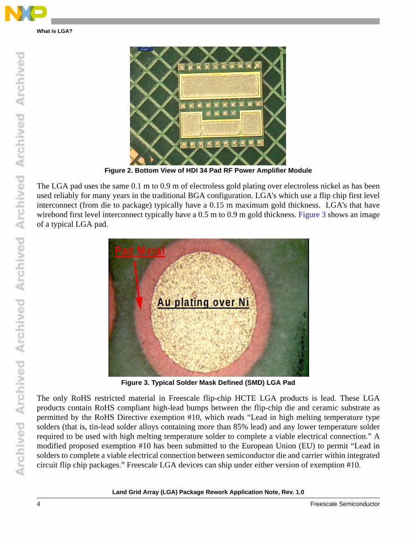
Freescale’s product portfolio also includes LGA packages with organic laminate substrates. These mayfeature High Density Interconnect (HDI) substrates or Bismaleimide Triazine (BT) substrates. In somecases an array of joints similar to the BGA may be presented. More often, the lands are square, rectangular,or irregular, as seen in these illustrations of the 34 I/O RF Power Amplifier Module.
The LGA solder interconnect is formed solely by solder paste applied at board assembly because there areno spheres attached to the LGA. This results in a lower stand-off height of approximately 0.06 mm to 0.10mm, depending on solder paste volume and printed circuit board (PCB) geometry.
HCTE flip-chip devices do not require spheres because the coefficient of thermal expansion (CTE) ofHCTE substrates matches very closely to that of the typical PCB. The HCTE substrate is a glass-filled,low temperature co-fired ceramic (LTCC) with a CTE of 12.3 ppm/ºC1. Likewise, the CTE for the organicalternative substrate materials closely matches the CTE of the mother board materials, ~16 ppm/oC.Typically, most epoxy-glass or polyimide-glass PCBs have a CTE of 16–22 ppm/ºC.
Figure 1. Top and Bottom View of HCTE 360 Pad LGA Device
1. The unit ppm/ºC stands for parts per million per degree Centigrade. Using HCTE as an example, if the temperature of one million millimeters of material is increased 1ºC, that material would expand 12.3 mm.
What is LGA?
Land Grid Array (LGA) Package Rework Application Note, Rev. 1.0
4 Freescale Semiconductor
Figure 2. Bottom View of HDI 34 Pad RF Power Amplifier Module
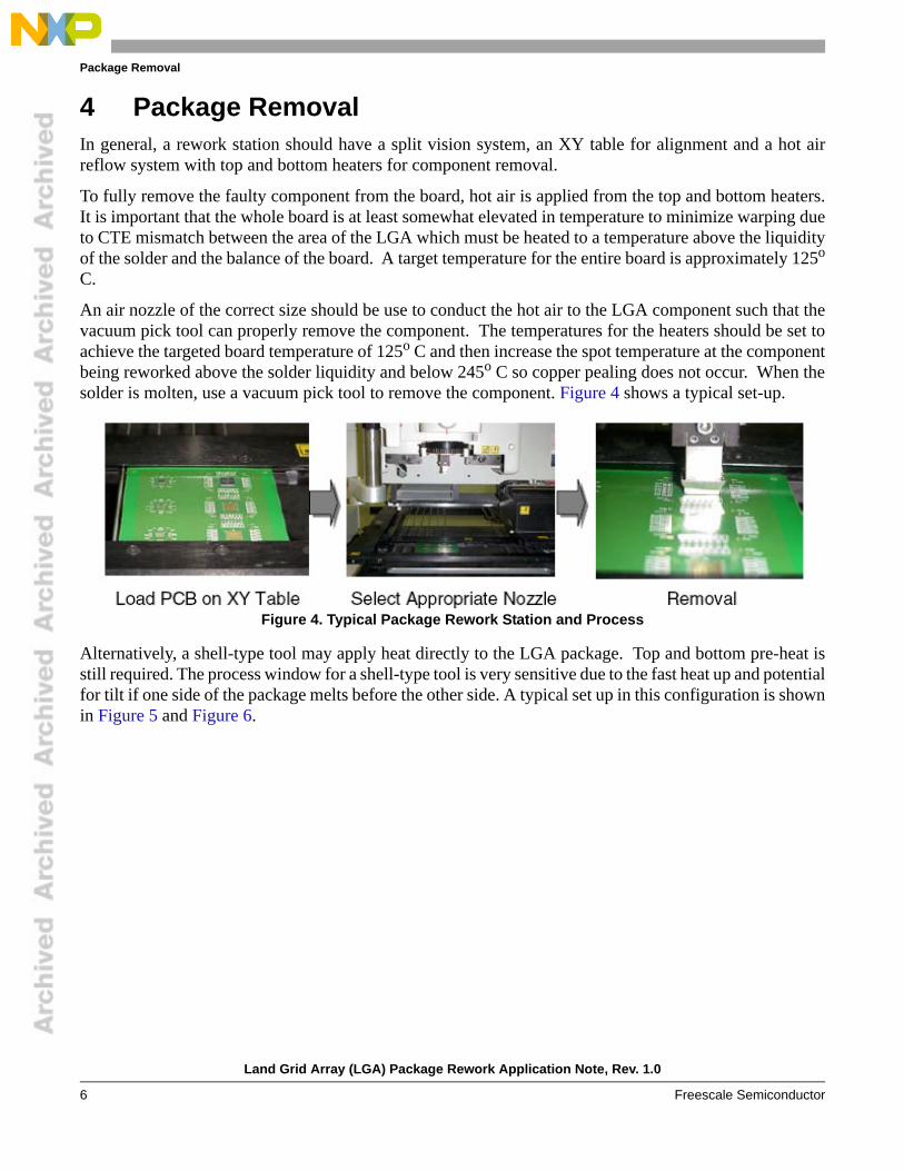
The LGA pad uses the same 0.1 m to 0.9 m of electroless gold plating over electroless nickel as has beenused reliably for many years in the traditional BGA configuration. LGA’s which use a flip chip first levelinterconnect (from die to package) typically have a 0.15 m maximum gold thickness. LGA’s that havewirebond first level interconnect typically have a 0.5 m to 0.9 m gold thickness. Figure 3 shows an imageof a typical LGA pad.
Figure 3. Typical Solder Mask Defined (SMD) LGA Pad
The only RoHS restricted material in Freescale flip-chip HCTE LGA products is lead. These LGAproducts contain RoHS compliant high-lead bumps between the flip-chip die and ceramic substrate aspermitted by the RoHS Directive exemption #10, which reads “Lead in high melting temperature typesolders (that is, tin-lead solder alloys containing more than 85% lead) and any lower temperature solderrequired to be used with high melting temperature solder to complete a viable electrical connection.” Amodified proposed exemption #10 has been submitted to the European Union (EU) to permit “Lead insolders to complete a viable electrical connection between semiconductor die and carrier within integratedcircuit flip chip packages.” Freescale LGA devices can ship under either version of exemption #10.
Au plating over N i
Pad M etal
LGA Rework
Land Grid Array (LGA) Package Rework Application Note, Rev. 1.0
Freescale Semiconductor 5
Freescale wirebonded LGA products have no lead in them. Lead-free solders and die attach materials areused to attach the integrated circuit device and any discrete passive components within the package to thesubstrate.
2.1 Benefits of LGASome benefits of the LGA package over a BGA package include:
• LGA devices can be used for either lead containing or lead-free assemblies depending on the surface mount technology (SMT) assembly solder pasted used.
• LGA eliminates risk that customers receive components with missing or damaged spheres due to shipping or handling.
• LGA devices have a lower mounted height than BGA. This can allow for more space above the device for a heat sink solution or for small form-factor applications.
• Board-level reliability significantly exceeds customer requirements when the design and process recommendations are followed.
• The durability of LGA in mechanical drop is typically greater than a BGA that is not underfilled.• LGA can use the same recommended board assembly process as CBGA.
3 LGA Rework
3.1 Solder MethodsSee Freescale Applications Note AN2920 for direction on how to perform assembly of Ceramic substratebased LGA.
3.2 ESD ProtectionProper ESD protection must be taken by the operator when handling electronic devices. Appropriate wrist and foot straps must be worn by the operator when handling these packages and reworking PCB boards.
3.3 Other ReferencesRework is LGA is very similar to the rework of Quad Flat No-lead (QFN) packages, covered in FreescaleApplications Note AN1902.
3.4 PCB PreparationDuring the package removal process the PCB will be heated. To the extent that moisture will becatastrophically driven from other components on the PCB and within the PCB there is a risk of productdamage. In order to prevent such “popcorn” failures of components due to adsorbed moisture it isrecommended that the PCBs should have had strict control for storage in Nitrogen Cabinets or a prebake(e.g. 125o C for 16 hour for boards with SMT components or 95o C for 16 hours for boards withtemperature sensitive components) to remove the moisture from the PCB prior to removal of the LGA.
Package Removal
Land Grid Array (LGA) Package Rework Application Note, Rev. 1.0
6 Freescale Semiconductor
4 Package RemovalIn general, a rework station should have a split vision system, an XY table for alignment and a hot airreflow system with top and bottom heaters for component removal.
To fully remove the faulty component from the board, hot air is applied from the top and bottom heaters.It is important that the whole board is at least somewhat elevated in temperature to minimize warping dueto CTE mismatch between the area of the LGA which must be heated to a temperature above the liquidityof the solder and the balance of the board. A target temperature for the entire board is approximately 125o
C.
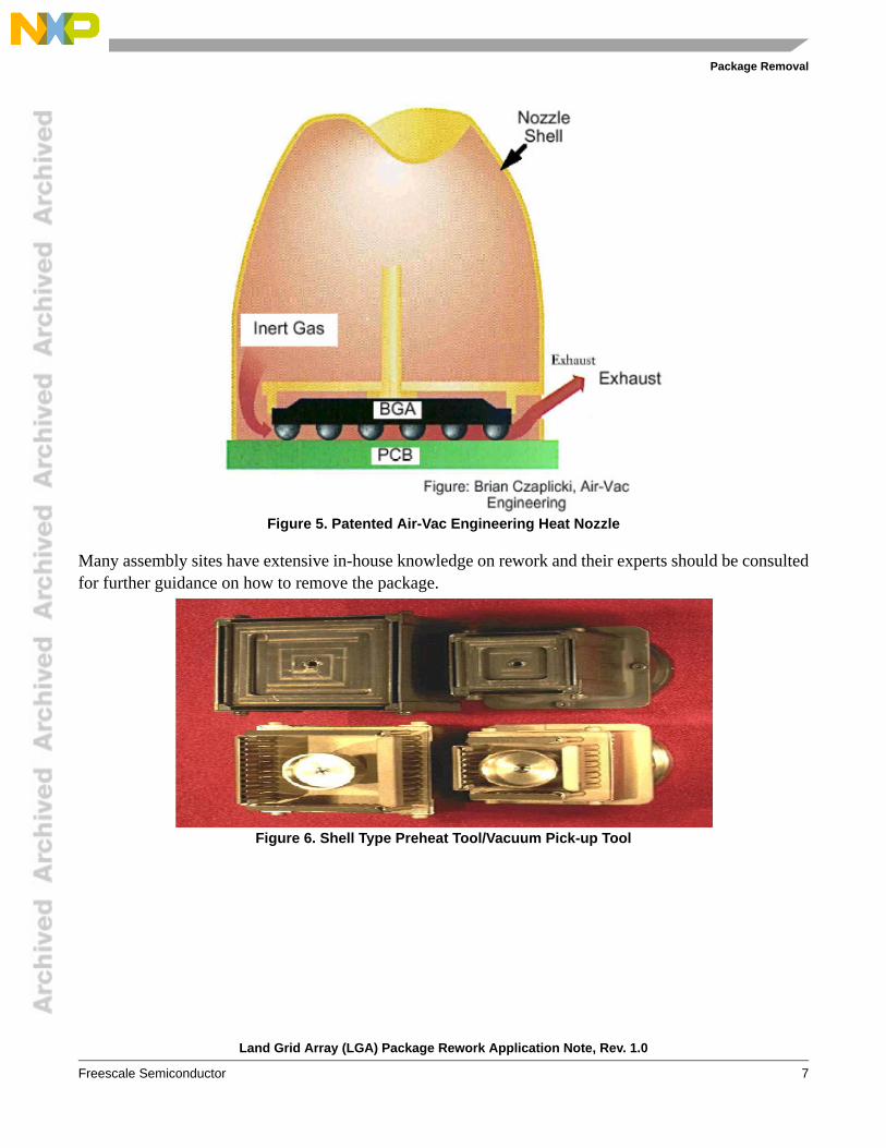
An air nozzle of the correct size should be use to conduct the hot air to the LGA component such that thevacuum pick tool can properly remove the component. The temperatures for the heaters should be set toachieve the targeted board temperature of 125o C and then increase the spot temperature at the componentbeing reworked above the solder liquidity and below 245o C so copper pealing does not occur. When thesolder is molten, use a vacuum pick tool to remove the component. Figure 4 shows a typical set-up.
Figure 4. Typical Package Rework Station and Process
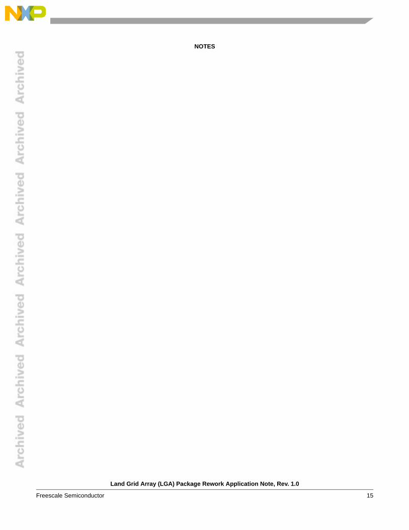
Alternatively, a shell-type tool may apply heat directly to the LGA package. Top and bottom pre-heat isstill required. The process window for a shell-type tool is very sensitive due to the fast heat up and potentialfor tilt if one side of the package melts before the other side. A typical set up in this configuration is shownin Figure 5 and Figure 6.
Many assembly sites have extensive in-house knowledge on rework and their experts should be consultedfor further guidance on how to remove the package.
Figure 6. Shell Type Preheat Tool/Vacuum Pick-up Tool
Package Removal
Land Grid Array (LGA) Package Rework Application Note, Rev. 1.0
8 Freescale Semiconductor
4.1 Package DisposalFreescale follows standard component level qualification standards for packages and these include threesolder reflows survivability. A package that has been attached to PCB and then removed has seen twosolder reflows and if the PCB is double sided, then the package has seen three solder reflows. Thus thepackage is at or near the end of the tested and qualified range of known survivability. The removed LGApackage should be properly disposed of so that they will not mix in with new LGA components.
4.2 Site PreparationOnce the LGA component is removed, the site should be cleaned and dressed to prepare for the newcomponent placement. A de-soldering station can be used for solder dressing. However, using a vacuumtool to remove excess solder while the PCB is still hot from the part removal eliminates a furthertemperature cycle on the board. A solder wicking braid may also be used to remove excess solder. This istypically a manual operation that puts a premium on operator skill and experience. The appliedtemperature should not exceed 245o C. Otherwise, the copper pad on the PCB may peel off.
4.3 Solder Paste PrintingUnless otherwise indicated, Freescale studies discussed in this document use Indium no clean NC-SMQ®230 flux and Indalloy® 241 solder paste made up of 95.5Sn/3.8Ag/0.7Cu. Devices were soldered to boardsusing the reflow profile shown in Section 4.6, “Reflow Profile”.
Flux should be applied uniformly but sparingly to the part for pre-tinned parts. Alternative fluxes to theNC-SMQ® 230 flux should be compatible with the production cleaning strategy. Flux is not used insystems that involve direct application of solder paste to the PCB during rework.
4.3.1 Manual Dispense (Not Recommended)The operator may use a needle to dispense paste directly to the solderable areas on the PCB if there isinsufficient paste remaining on the board. This is not recommended.
4.3.2 Mini-StencilThe user may fabricate a mini-stencil with the same stencil thickness, aperture opening and pattern as thenormal production stencil that was used to originally place the component. The mini-stencil is placed onthe position where the package will be placed and aligned to match the interconnect areas on the PCB. Theoperator uses a mini-squeegee blade to deposit solder paste on the mini-stencil and spread the paste intothe mini-stencil openings. The printed pads should be inspected to ensure even and sufficient solder pastebefore component placement. See Figure 7.
Package Removal
Land Grid Array (LGA) Package Rework Application Note, Rev. 1.0
Freescale Semiconductor 9
Figure 7. Mini-stencil and Mini-squeegee
4.3.3 Locally Pre-tinned ComponentsThe user may prepare a stencil for off-line tinning. A unit is placed in a fixture and a stencil which matchesthe production stencil in thickness, aperture openings and patterns is used to deposit solder paste on thecomponent. Depending on the volume of pre-tinned units desired, this fixture/stencil operation may be aone-up operation or involve a fixture with multiple sites so multiple units may have paste deposited at onetime. Note that some adjustments to the aperture openings for large heat sink lands may be necessary sothe post-reflow height of the solder paste is similar between the heat sink and the signal lands. It isFreescale’s experience that exactly matching the conventional assembly paste print patterns on the largelands will lead to too little solder on the pre-tinned heat sink areas. The parts with the solder paste are thenput through a solder reflow pass (See Section 4.5, “Solder Reflow Profile for Lead-Free Paste”), cleaned,and set aside to use exclusively for rework.
Package Removal
Land Grid Array (LGA) Package Rework Application Note, Rev. 1.0
10 Freescale Semiconductor
Figure 8. Pre-tinning an LGA
Alternatively, the customer may obtain a clean ceramic plate. Stencil print the production solder pastepattern on the plate and place a component on the solder paste pattern. Reflow the assembly per the profilein Figure 12. Remove the part from the ceramic plate (since the solder will not wet to the ceramic) andclean the part. The ceramic plate may be cleaned and re-used.
4.3.4 Purchase Pre-tinned ComponentsThe user may approach a local subcontractor or Freescale to purchase parts that have been pre-tinned.
4.4 Place the ComponentAny rework station should have good look-up or look-down capability with video or optical vision.
4.4.1 Manual Placement (Not Recommended)The operator picks up the replacement component and places it on the PCB, taking care to align the partas closely as possible so the lands on the component and the PCB are properly aligned. With fine pitchcomponents there is clearly a risk of solder short circuits with this method. Pre-tinned parts, where thepaste has already been through one reflow presents a lower risk of solder shorts than solutions that have“wet” solder paste.
Package Removal
Land Grid Array (LGA) Package Rework Application Note, Rev. 1.0
Freescale Semiconductor 11
4.4.2 Semi-automatic Placement (Recommended)A vacuum nozzle is used to pick the new package up. The split vision system displays images of both theLGA lands and the footprint on the PCB. The two superimposed images are aligned manually by adjustingthe XY table. Once the PCB and package are aligned, the package is placed down on the PCB (SeeFigure 9.
PCB Image Captured by Camera Superimpose LGA on PCBFigure 9. Semi-Automatic Component Placement
4.4.3 LGA Self AlignmentArray LGA and BGA have been shown to be equally tolerant of up to 50% off-pad misplacement. Bothpackage types exhibit self-alignment in any direction including X-axis shift, Y-axis shift, and rotationalmisplacement. Figure 10 shows device misplacement and Figure 11 shows a 100% self-aligned soldereddown device after 50% misplacement was induced.
The best experience with self-alignment has been seen with parts that feature arrays of lands. Parts withirregular solderable features on the bottom of the package and large ground planes do not show a strongself-alignment capability. For those packages, it is clear that there is no substitute for careful, preciseplacement of the component on the PCB.
Figure 10. LGA Misplacement of 50%
Package Removal
Land Grid Array (LGA) Package Rework Application Note, Rev. 1.0
12 Freescale Semiconductor
Figure 11. X-ray of perfectly Self-aligned LGA After Misplacement
4.5 Solder Reflow Profile for Lead-Free PasteOptimal reflow profile depends on solder paste properties and should be optimized and proven out as partof an overall process development. The following guidelines represent good soldering practices to helpyield high quality assemblies with minimum rework.
It is important to provide a solder reflow profile that matches the solder paste supplier’s recommendations.Some fluxes need a long dwell time below the temperature of 180o C, while others will be burned up in along dwell. Temperatures out of bounds of the solder paste flux recommendation could result in poorsolderability of all components on the board. All solder paste suppliers should recommend an ideal reflowprofile to give the best solderability.
Freescale has achieved good results with Indalloy® 241 with a peak temp of 235o C to 250o C and a dwelltime above 221o C for greater than 50 seconds and less than 80 seconds as shown in Figure 12.
In IR or convection processes the temperature can vary greatly across the PC board depending on thefurnace type, size and mass of components, and the location of components on the assembly. Profiles mustbe carefully tested to determine the hottest and coolest points on the assembly. The hottest and coolestpoints should fall within recommended temperatures in the reflow profile. To monitor the process,thermocouples must be carefully attached with very small amounts of thermally conductive grease orepoxy directly to the solder joint interface between the package and board.
Solder Joints 100%Aligned to Pads
Die Bumps (C4)
Package Removal
Land Grid Array (LGA) Package Rework Application Note, Rev. 1.0
Freescale Semiconductor 13
4.6 Reflow ProfileExperience with specific products and production equipment sets may lead users of LGA to have slightly different profiles that are optimized to their local conditions.
Figure 12. Typical Freescale Pb-Free Board Assembly Reflow Profile (Example is for BGA, LGA Uses Same)
4.6.1 Reflow AtmosphereAssembly and reliability studies were conducted in a furnace with an air atmosphere. This setup producesexcellent results. However, there are advantages in using a nitrogen atmosphere, such as more completewetting and a reduction in solder joint voids.
4.6.2 Cleaning Under LGADue to the lower stand-off height of the LGA device, no-clean solder pastes are recommended. Full dryingof no-clean paste fluxes as a result of the reflow process must be ensured. This may require longer reflowprofiles and/or peak temperatures toward the high end of the process window, as recommended by thesolder paste vendor. Instances of uncured flux residues after reflow have been encountered with LGA. Itis believed that uncured flux residues could lead to corrosion and/or shorting in accelerated testing andpossibly the field. The presence and extent of uncured flux residues can be detected by mechanical removalof the LGA after reflow as part of the overall assembly development process. Cross-sectioning and flatsectioning are also recommended to assess not only residues, but overall joint geometry.
Temp (
°C)
Time (mins)
Notes : 1. Reflow profiles are flux and solder alloy 2. Profile shown here is used for Indium no clean NC-SMQ® 230
Indalloy® 241 solder paste with 95.5Sn3.8Ag0.7Cu (http://www.indium.com/)
3. Two thermocouples are embedded into PBGA solder joints at expected hottest and coolest locations on the PWB
4. All times listed are +/-5 secs
Average Ramp from 50 to 150 ° C at 1.4 ° C/s
Time from150 ° C to200 ° C of 80s
Time > 183°C of160s to 170s
Time > 221°Cmelt of 60s to70s
TC1 peak = 247 ° C
TC2 peak = 243 ° C
LGA Reliability
Land Grid Array (LGA) Package Rework Application Note, Rev. 1.0
14 Freescale Semiconductor
Solder flux technologies have improved dramatically in recent years, to the point that most of the industryis using no-clean fluxes. Some of these fluxes require specific reflow profiles. The flux vendor’srecommendations should always be followed precisely taking precedent over any the guidelines describedin this application note.
Freescale has investigated water soluble solder pastes that do require cleaning in combination with LGA.Using an ion chromatograph, it has been shown that assembly cleanliness is very acceptable, withchlorides detected at 2.11 g/in2, and bromides at a level of 0.36 g/in2, following a water clean.
5 LGA Reliability
5.1 Solder Joint Reliability in Temperature CyclingSee Freescale Applications Note AN2920, Manufacturing with the Land Grid Array Package for more details.
5.2 Mechanical DurabilityPerformance of packages in drop testing depends critically on the thickness of the PCB, the position of thecomponents on the PCB, how the PCB is braced within the application, the customer test conditions andthe design of the LGA footprint. Consult with the Application Team for any specific package performanceinformation that may be available.
5.3 Application SpaceThe application should drive the PCB land construction details. NSMD lands on the PCB are known togive better temperature cycling reliability (See AN2920 for details). However, Freescale has found thatSMD pads improved the mechanical durability compared to NSMD pads in drop testing by 10% asmeasured by first strain to failure in a single impact 4 point bend test. The user should select a PCB landconfiguration based on their own assessments of their product, bearing in mind the general applicationspace. Freescale has observed a greater sensitivity to mechanical durability in drop testing for somemarket segments such as cell phones, portable music players, flash memory, etc. Other business segmentssuch as computers, servers, and base stations emphasize good performance with respect to temperaturecycling fatigue.
6 References• AN2920 Manufacturing With the Land Grid Array Package• AN1902 Quad Flat Pack No-lead (QFN)• Freescale CBGA Customer Presentation
(http://www.freescale.com/files/32bit/doc/package_info/CBGAPRES.pdf)For assistance or answers to any questions on the information presented in this note, contact the appropriate Freescale product applications team.
NOTES
Land Grid Array (LGA) Package Rework Application Note, Rev. 1.0
USA/Europe or Locations Not Listed:Freescale SemiconductorTechnical Information Center, CH3701300 N. Alma School RoadChandler, Arizona 85224+1-800-521-6274 or [email protected]
Japan:Freescale Semiconductor Japan Ltd.HeadquartersARCO Tower 15F1-8-1, Shimo-Meguro, Meguro-ku,Tokyo 153-0064, Japan0120 191014 or +81 3 5437 [email protected]
Asia/Pacific:Freescale Semiconductor Hong Kong Ltd.Technical Information Center2 Dai King StreetTai Po Industrial EstateTai Po, N.T., Hong Kong+800 2666 [email protected]
For Literature Requests Only:Freescale Semiconductor Literature Distribution CenterP.O. Box 5405Denver, Colorado 802171-800-521-6274 or 303-675-2140Fax: [email protected]
Information in this document is provided solely to enable system and software implementers to use Freescale Semiconductor products. There are no express or implied copyright licenses granted hereunder to design or fabricate any integrated circuits or integrated circuits based on the information in this document.Freescale Semiconductor reserves the right to make changes without further notice to any products herein. Freescale Semiconductor makes no warranty, representation or guarantee regarding the suitability of its products for any particular purpose, nor does Freescale Semiconductor assume any liability arising out of the application or use of any product or circuit, and specifically disclaims any and all liability, including without limitation consequential or incidental damages. “Typical” parameters that may be provided in Freescale Semiconductor data sheets and/or specifications can and do vary in different applications and actual performance may vary over time. All operating parameters, including “Typicals”, must be validated for each customer application by customer’s technical experts. Freescale Semiconductor does not convey any license under its patent rights nor the rights of others. Freescale Semiconductor products are not designed, intended, or authorized for use as components in systems intended for surgical implant into the body, or other applications intended to support or sustain life, or for any other application in which the failure of the Freescale Semiconductor product could create a situation where personal injury or death may occur. Should Buyer purchase or use Freescale Semiconductor products for any such unintended or unauthorized application, Buyer shall indemnify and hold Freescale Semiconductor and its officers, employees, subsidiaries, affiliates, and distributors harmless against all claims, costs, damages, and expenses, and reasonable attorney fees arising out of, directly or indirectly, any claim of personal injury or death associated with such unintended or unauthorized use, even if such claim alleges that Freescale Semiconductor was negligent regarding the design or manufacture of the part.
Freescale™ and the Freescale logo are trademarks of Freescale Semiconductor, Inc. All other product or service names are the property of their respective owners.