4-1 - , ,I,/', .:... .... _ _-. LANDING LANDING GEAR SYSTEM Trouble Shooting Landing Gear Actuator Removal Installation Manual Extension System Removal Installation Main Landing Gear Removal Disassembly Assembly Installation Main Wheel Alignment Removal and Disassembly of Main Gear Torque Links Assembly and Installation of Main Gear Torque Links Main Landing Gear Doors Removal Installation Rigging Main Landing Gear Retracting Linkage 4-21 Removal 4-21 Installation 4-21 Rigging of Main Landing Gear 4-24 Adjustment of Landing Gear Safety Switch 4-26A Adjustment of Landing Gear Warning System 4-27 Nose Gear 4-28 Removal 4-31 Disassembly 4-31 Assembly 4-31 Installation 4-33 Removal and Disassembly of Nose Gear Torque Link Assemblies 4-34 Assembly and Installation of Nose Gear Torque Link Assemblies 4-34 Nose Cear Doors 4-34 411 SERVICE MANUAL SECTION 4 ....... . , ....... .... LANDIN6 6EAR AND BRAKE SYSTEM GEAR AND BRAKE SYSTEM Table of Contents Page 4-2 4-2 4-6 4-6 4-7 4-9 4-9 4-9 4-11 4-11 4-13 4-15 4-15 4-17 4-17 4-17 4-19 4-19 4-19 4-19 Removal Installation Rigging Nose Gear Retracting Linkage Removal Installation Rigging Nose Gear Nose Gear Shimmy Dampener Removal Disassembly Assembly Installation Nose Gear Steering System Removal Installation Rigging Nose Wheel and Tire Assembly Removal Disassembly Installation Main Wheel and Tire Removal Disassembly Assembly Installation BRAKE SYSTEM - MAIN AND PARKING Trouble Shooting Removal Installation Main Wheel Brake Disassembly Main Wheel Brake Lining Replacement Assembly of Main Wheel Brake Installation of Main Wheel Brake Bleeding the Brake System Parking Brake Valve Master Cylinder Removal Disassembly Assembly Ins tallat io n 4-34 4-34 4-34 4-35 4-35 4-36 4-37 4-41 4-41 4-41 4-43 4-43 4-43 4-43 4-43 4-46 4-46 4-46 4-46 4-46 4-46 4-46 4-46 4-48 4-48 4-48 4-49 4-51 4-51 4-51 4-52 4-52 4-52 4-52 4-52 4-52 4-53 4-53 4-55 4-55
Transcript
4-1
_-~- shy I middotimiddot~~~k ~ ~~~~~ _ I~ _-
LANDING
LANDING GEAR SYSTEM Trouble Shooting Landing Gear Actuator
Removal Installation
Manual Extension System Removal Installation
Main Landing Gear Removal Disassembly Assembly Installation Main Wheel Alignment Removal and Disassembly of Main
Gear Torque Links Assembly and Installation of Main
Gear Torque Links Main Landing Gear Doors
Removal Installation Rigging
Main Landing Gear Retracting Linkage 4-21 Removal 4-21 Installation 4-21
Rigging of Main Landing Gear 4-24 Adjustment of Landing Gear Safety
Switch 4-26A Adjustment of Landing Gear Warning
System 4-27 Nose Gear 4-28
Removal 4-31 Disassembly 4-31 Assembly 4-31 Installation 4-33 Removal and Disassembly of Nose
Gear Torque Link Assemblies 4-34 Assembly and Installation of Nose
Gear Torque Link Assemblies 4-34 Nose Cear Doors 4-34
411 SERVICE MANUAL
SECTION 4
--~ ~-~--- __~~_
LANDIN6 6EAR AND BRAKE SYSTEM
GEAR AND BRAKE SYSTEM
Table of Contents
Page
4-2 4-2 4-6 4-6 4-7 4-9 4-9 4-9
4-11 4-11 4-13 4-15 4-15 4-17
4-17
4-17 4-19 4-19 4-19 4-19
Removal Installation Rigging
Nose Gear Retracting Linkage Removal Installation
Rigging Nose Gear Nose Gear Shimmy Dampener
Removal Disassembly Assembly Installation
Nose Gear Steering System Removal Installation Rigging
Nose Wheel and Tire Assembly Removal Disassembly Installation
Main Wheel and Tire Removal Disassembly Assembly Installation
BRAKE SYSTEM - MAIN AND PARKING Trouble Shooting Removal Installation Main Wheel Brake Disassembly Main Wheel Brake Lining Replacement Assembly of Main Wheel Brake Installation of Main Wheel Brake Bleeding the Brake System Parking Brake Valve Master Cylinder
4-2 LANDING GEA~ AND 411 SERVICE MANUAL B~AKE SYSTEM
LANDING GEAR
The landing gear is a fully-retractable tricycle landshying gear consisting of a main gear located aft of each engine nacelle and a nose gear located near the forshyward end of the fuselage Each landing gear is mechshyanically connected to a single gear box which is norshymally driven by an electric motor In the event of landing gear electrical system failure the landing
Trouble Shooting the Landing Gear System
gear can be extended by operating a hand crank loshycated at the right side of the pilots seat Landing gear over-travel during operation is prevented by
limit switches which open the electrical circuit to the motor when the correct amount of travel has been attained A safety switch prevents accidental retracshytion on the ground by opening the landing gear elecshytrical circuit while the weight of the aircraft is on the gear
TROUBLE PROBABLE CAUSE CORRECTION
LANDING GEAR FAILS TO RETRACT - GEAR MOTOR OPERA TES
LANDING GEAR FAILS TO RETRACT - GEAR MOTOR DOES NOT OPERATE
LANDING GEAR FAILS TO RETRACT COMshyPLETELY
ONE LANDING GEAR FAILS TO RETRACT
Manual extension crank improperly stowed
Defective landing gear actuator
Defective reduction unit
Pin sheared on gear motor shaft
Broken bolts or retracting linkage or disconnected retracting linkage
Circuit breaker out
Defective circuit breaker
Insufficient electrtcalpower
Defective UP limit switch
Defective landing gear safety switch
Incorrectly adjusted landing gear safety switch
Defective landing gear relay
Defective landing gear switch
Defective landing gear motor
Defective UP electrical circuit
Landing gear incorrectly rigged for retracted position
Circuit breaker out due to overshyload caused by incorrect landing gear rigging
Circuit breaker out due to overshyload caused by defective retracting linkage
UP limit SWitch incorrectly adjusted
Retracting linkage to affected gear broken or disconnected
Stow crank properly
Replace actuator
Replace reduction unit
Replace pin
Replace broken parts Connect linkage if disconnected
Reset circuit breaker
Replace circuit breaker
Recharge batteries Check voltage regulashytors
Replace switch Adjust in accordance with rigging procedure
Replace switch
Adjust safety switch
Replace relay
Replace switch
Replace motor
Repair circuit
Rig in accordance with rigging procedure
Reset circuit breaker and rig in accordance with rigging procedure
Reset circuit breaker replace defective linkage rig in accordance with rigging procedure
Adjust in accordance with rigging procedure
Replace broken parts Connect linkage if disconnected Rig in accordance with rigging procedurebull
Replace switch and adjust in accordance with rigging procedure
Replace switch and adjust in accordance with rigging procedure
Locate and repair
Adjust switch in accordance with rigging procedure
Replace switch and adjust in accordance with rigging procedure
Reset circuit breaker
Replace circuit breaker
Adjust in accordance with rigging procedure
Replace switch and adjust in accordance with rigging procedure
Repair circuit
Replace horn or flasher unit
Reset circuit breaker
Replace circuit breaker
Replace switch and adjust in accordance with rigging procedure
Repair circuit
Replace horn
Adjust in accordance with rigging procedure
Replace switch and adjust in accordance with rigging procedure
Rig doors in accordance with rigging procedure
Replace defective linkage
Service shimmy dampener in accordance with Section 2
Replace defective seals andor piston
Replace roll pin
Replace worn housing andor attaching bolt
Replace tires when tread is worn unevenly or has flat soots
4-6 LANDINe SEA AND 411 SERVICE MANUAL BAIlt SVSTM
TROUBLE PROBABLE CAUSE CORRECTION
LANDING GEAR SHIMshyMIES DURING FAST TAXI TAKEOFF OR LANDING (CONTINUED)
EXCESSIVE OR UNshyEVEN WEAR ON TIRES
NOSE GEAR FAILS TO STEER PROPERLY
NOSE GEAR FAILS TO STRAIGHTEN WHEN LANDING GEAR EXshyTENDS
NOSE GEAR FAILS TO STRAIGHTEN WHEN LANDING GEAR REshyTRACTS
ATTITUDE OF AIRshyCRAFT ON GROUND IS INCORRECT
STRUT BOTTOMS ON NORMAL LANDING OR TAXIING ON ROUGH GROUND
STRUT DEFLATED WITH EVIDENCE OF FL urn LEAKAGE
Worn or loose wheel bearings
Excessive clearance between upper and lower torque links
Worn torque link bushings
Incorrect operating pressure
Incorrect wheel alignment
Wear resulting from shimmy
Incorrect rigging of nose gear steering system
One brake dragging
Defective nose gear steering springs
Gimbal broken or damaged at the top of the nose strut
Incorrect rigging of nose gear steering system
Gimbal broken or damaged on top of the nose strut
Landing gear struts incorrectly inflated
Insufficient air andor fluid in strut
Defective internal parts in strut
Defective O-rings
Replace andor adjust bearings
Adjust clearance in accordance with alignshyment procedure
Replace bushings
Inflate to correct pressure
Align in accordance with alignment proceshydure
See the preceding corrections for shimmy
Rig in accordance with nose gear steering procedure
Determine cause and correct
Replace springs
Replace defective gimbal
Rig in accordance with nose gear steering procedure
Replace defective gim bal
Inflate struts correctly
Service strut with proper amount of fluid and air
Replace defective parts
Determine which O-rings are defective and replace
Landing Gear Actuator
The landing gear actuator consists of an electric moshytor a reduction unit and a worm-and-sector assemshybly The actuator is normally operated by the elecshytric motor bowever linkage is provided to disengage the motor-driven reduction unit and engage the manshyual extension system which is linked directly to the actuator worm gear The bellcrank that operates the main landing gear drive tubes is attached to the upper end of tbe sector shaft which extends vertically througb the actuator assembly and the bellcrank that operates the nose gear drive tube is attached to the lower end of the sector shaft Adjustable limit SWitches are provided so tbat correct landing gear travel can be obtained
Removal of Landing Gear Actuator (See figure 4-1)
-- - _- L ----shy- J
a Jack the aircraft in accordance with Section 2 b Remove the rear seats and carpet c Remove cabin floor above landing gear actuator
and access hole cover from underside of fuselage beshyneath landing gear actuator d Release tension on retracting linkage by engagshying manual extension crank and operating a few turns toward the UP position e Disconnect nose gear forward push-pull tube (see
figure 4-1) from fork bolt i Disconnect both main landing gear drive tubes
from idler bellcranks g Remove the nose gear drive tube attached to lowshy
er bellcrank b Remove nut washer caps and bolt attaching
upper and lower bellcranks to the sector shaft I Lift upper bellcrank enough to allow main gear
drive tubes to be disconnected Remove nuts washshyers and bolts attaching main gear drive tubes to
-_ l ~
~
j
- middot~~~-~middot-7~-
LANDING GEAR AND 4-7411 SERVICE MANUAL BRAKE SYSTEM
upper bellcrank and slide both tubes outboard so they ( will not interfere with removal
j Disconnect manual extension disengage rod by removing cotter pin and clevis pin k Disconnect the manual extension drive tubes by
removing the three clevis pins washers and cotter pins then slide outer shaft aft and inner shaft forshyward to disconnect 1 Remove safetywire from bolts to be removed
then remove the four bolts and washers attaching reshyduction unit and actuator assembly to the aft bulkhead
NOTE
When removing the motor disconnect and tag all electrical wires at the quick-disconnects provided
m Remove switch brackets from actuator assembly Do not disturb switch adjustments except to replace switches or brackets
NOTE
If switches are to be replaced tag wires beshyfore disconnecting
n Remove the two bolts washers and nuts attachshying actuator assembly to forward bracket o Lift actuator assembly vertically and remove
from aircraft p Remove the lower bellcrank and spacer from end
of sector shaft
Installation of Landing Gear Actuator (See figure 4-1 )
a Install lower bellcrank on lower end of sector shaft
NOTE
When installing lower be llcrank align the index punch mark on the bellcrank with the chamfered spline on the sector shaft
b Position actuator assembly in position aligning manual extension outer and inner shaft so they will mate
NOTE
To facilitate installation install all actuator attaching bolts before any bolts are tightened
c Install the two bolts attaching the actuator to the forward mounting bracket
d Install the four bolts and washers attaching actushyator assembly and reduction unit to bulkhead e If motor was removed connect the electrical
wires at the quick-disconnect provided f Install switch brackets with bolts washers and
nuts
CAUTION
Check switches thoroughly for proper operashytion A faulty switch may cause damage to the landing gear actuator
g Tighten all nuts and bolts which were installed but not tightened h Safetywire bolts attaching actuator to the bulkshy
head I Connect manual extension drive tubes with clevis
pins and washers and safety with cotter pins j Connect the manual extension disengage rod with
clevis pin and safety with cotter pin k Position upper bellcrank above actuator assembly
slide main gear drive tubes inboard and attach to bell shycrank with bolts washers and nuts Install bolts with their threaded ends UP
NOTE
Main gear drive tubes must be installed with half-round side of end fitting upwards
1 Place spacer and upper bellcrank on sector shaft
NOTE
When installing upper bellcrank align the index punch mark on the bellcrank with the chamfered spline on the sector shaft
rn Insure that lower bellcrank and spacers are corshyrectly in position and install bolt caps washer and nut n Attach nose gear drive tube to lower bellcrank
with bolt washer and nut o Connect main landing gear drive tubes to idler
bellcranks with bolts spacers and nuts p Connect forward push-pull tube to fork bolt with
bolt and nut q Perform an operational check of landing gear
checking especially that limit switches are correctly adjusted and landing gear is correctly rigged r Install cabin floor panel and access hole cover on
underside of fuselage beneath landing gear actuator s Install rear carpet and seats removed for removshy
al of actuator t After making sure landing gear is DOWN and locked remove aircraft from jacks
4-8 LANDING eEAR AND 411 SERVICE MANUAL BRAKE SYSTEM
I
J
27
Figure 4-1 Landing Gear Actuator Installation
Ciange 3
- v--_7 bull -- ~~-~j-_T--~~ = ~ -shy
r
-- 0- _--j~~~-~--_~ ~ L~ bullbull _
411 SERVICE MANUAL LANDING GEAR AND 4-9 BRAKE SYSTEM
i Remove lower rod assembly by removing cotter Manual Extension System pins washer and clevis pins attaching roc assembly
to lower bellcrank and landing gear actuator The manual extension system consists of a hand j Remove lower bellcrank by removing nut washer crank which is connected to the landing gear actuator spacer and bolt by an arrangement of chain and sprockets bellcranks k Remove chain tighteners by removing attaching miter gears and push-pull rods The hand crank screws and washers then remove the adjusting screw located at the right of the pilots seat) is provided with washers and nut a spring-loaded release button which unlocks the hand 1 If support bracket is to be disassembled further crank so that it can be folded into the stowed position proceed as follows When the hand crank is folded it disengages the manshy 1 Remove roll pins from sprocket and miter gear ual extension system when unfolded into its operatshy and slide shaft out of bracket and remove sprocket ing position the hand crank disengages the normal and miter gear landing gear operating system 2 Disconnect drive tube from actuator by removshy
ing cotter pin washer and clevis pins then slide shaft with other miter gear aft and remove roll pill
Removal of Manual Extension System (See figure then remove the other miter gear 4-2)
NOTE a Remove pilots seat b Remove left rear seats and carpet to gain access If bushings in the support bracket are to be reshy
to cover over extension system placed the landing gear actuator must be reshyc Remove access hole cover from cabin floor above moved then the support bracket removed from
the landing gear actuator front spar The oilite bearings in which the d Remove chain guards by removing the three at shy gear shafts rotate are a press fit and should
taching screws be removed only for replacement e Remove chain by disconnecting at the master link I Remove crank handle and shaft assembly as folshy
lows Installation of Manual Extension System (See figure 1 Remove roll pin and washer from shaft 4-2) 2 Remove cotter pin and clevis pin from spool 3 Pull crank handle and shaft from supports reshy a If the support bracket has been disassembled
moving spool as shaft is pulled through it without removing the landing gear actuator assemble g Remove upper rod assembly by removing cotter as follows
pins washers and clevis pins attaching rod assembly 1 Insert actuator drive tube thru the aft bushing to the bellcranks then install miter gear on shaft and insert roll pin h Remove upper bellcrank by removing nut washer 2 Holding sprocket and other miter gear in posishy
and bolt then remove bushing from bellcrank tion slide the shaft thru the gear and sprocket then insert the two roll pins
4-10 LANOINa 411 SERVICE MANUAL BRAKE s aEAR AND
YSTEM
Figure 4-2 bull Manual Extens ion System Installation
b Connect drive tubes from landing gear actuator c Install chain tighteners with attaching screws
and washers then install adjusting screw washers and nut but do not tighten at this time d Install lower bellerank with bolt spacer washer
and nut e Inse rt bushing into upper be l lc rank then install
bellcrank with bolts washers and nuts f If disassembled reassemble crank handle and
shaft with pins cotter pins nut and bolt g Install crank handle and shaft assembly as folshy
lows 1 Insert crank handle and shaft through inboard
support spool and the outboard support 2 Engage upper bellcrank with spool align spool
attaching holes and install pin and cotter pin 3 Place washer and collar on the shaft and install
roll pin and safety This washer is to remove end play h Install chain on sprockets and connect with masshy
ter link Adjust chain tighteners and tighten adjusting screw and nut I Attach the lower rod assembly to the lower bell shy
crank and landing gear actuator With pins and washers and safety with cotter pins j Attach upper rod assembly to bellcranks with pins
washers and cotter pins k If the length of the upper or lower rod has been
changed adjust as follows 1 Place crank in operating position 2 Adjust lower rod assembly to a length of approxshy
imately 18 10 inches measured between the rod end bolt holes and install
3 Pull lower rod assembly forward until internal gear in landing gear actuator reaches the end of its travel adjust upper rod assembly so that rod and bolt holes align with holes in upper and lower be llc ranks
4 Lengthen upper rod assembly one-half turn and install
If the upper rod assembly adjustment cannot be obtained because an excessive amount of threads would be exposed readjust the lower rod assembly to obtain the desired result and repeat steps 3 and 4
1 Perform an operational check to see that manual extension functions properly
CAUTION
Do not use the manual extension system to fully retract the landing gear except when manually pushing upward on all landing gears to relieve strain on manual extension system
m Install chain guards with attaching screws n Install access hole cover on cabin floor above the
land ing gear actuator o Install rear carpet and seats
Main Landing Gear
Each main landing gear consists of a wheel and tire assembly brake assembly lower piston assembly cantilever axle upper cylinder assembly and torque links The Air-oleo shock strut contains an orifice and tapered metering pin which vary the resistance to shock according to its severity During extension and retraction the landing gear pivots on heavy-duty needle bearings by means of trunnion shafts attached to the upper cylinder assembly
Removal of Main Landing Gear (See figure 4 -3 )
a Jack the aircraft in accordance with Section 2
j
4-12 NOINe eEAR ANO 411 SERVICE MANUAL LA E SYSTEMBRAK
~12
14
DETAIL D
D
DETAIL B
B-~
Figure 4-3 Main Lan dimg Gear Ins ta llation
laquo
_ 2 ir~~~ ___d_ bull _
411 SERVICE MANUAL LANDINC3 C3EAR AND 4-13 BRAKE SYSTEM
Figure 4-3 Main Landing Gear Installation Callouts
b Drain brake system by loosening bleeder plug c Disconnect brake hose at forward wheel well
bulkhead union Plug hose and cap fittings to pervent entry of foreign matter
NOTE
Alternate to steps b and c 1 Remove 6 bolts thru brake cylinder asshysembly 2 Remove brake cylinder assembly from disc 3 Replace 6 bolts thru brake cylinder asshysembly using 38 or thicker board to hold linings in place 4 Remove hose clamps and tie brake asshysembly out of way for further work
d Remove safety switch and down indicator switch by removing attaching screws and nuts e Remove wire clamps and tie switches where they
will not interfere with gear removal f Release tension on retracting linkage by engaging
manual extension crank and operating a few turns toshyward the UP position g Disconnect the main landing gear doors h Disconnect retracting linkage as follows 1 Disconnect outboard push-pull tube from bell shy
crank by removing nuts washers and bolts 2 Disconnect upper side link from lower side link
by removing nuts washers and bolts i Remove roll pins from attaching shafts and inshy
sert AN6 bolt or puller tool j Support gear and pull attaching shafts
NOTE
Needle bearings in which the attaching shafts pivot are a press fit and should be removed only for replacement Bearings must be reshymoved by driving them toward the wheel well
13 Bolt 14 Bellcrank 15 Washer 16 Nut 17 Outboard Push-Pull Tube 18 Spacer 19 Down Indicator Switch 20 Spacer 21 Screw 22 Side Lock Link 23 Bracket 24 Nut
CAUTION
NOTE the amount of thickness of washers reshymoved These washers should be installed exactly as they were located before removal to insure proper alignment of side link assemshybly
Disassembly of Main Landing Gear (See figure 4-4)
a Completely deflate strut and after all the air has been expelled remove the valve body and drain fluid b Remove lower strut assembly from upper truss
assembly as follows 1 Disconnect the torque link brake hose clamps
bushings and safety switch bracket by removing the cotter pins nuts washers and bolts
2 Disconnect brake hose from brake at elbow and remove hose
3 Remove wheel and tire assembly and brake asshysembly from axle fitting
CAUTION
Removal and handling of the lower strut should be done with care to prevent the posshysibility of damage to exposed parts
c (See figure 4-4) Disassemble upper cylinder assembly as follows
1 Remove metering tube (4) from upper barrel assembly (38) by pulling straight out
CAUTION
If the metering pin and seal support are to be reshyinstalled use extreme caution during removal
2 Disconnect torque links (14) by removing nut (20) washer (21) bushing (19) clamp (16) and bolt (15)bull
3 Remove lock ring (27) scraper ring (28) and internal lock ring (29) 4 Pull piston assembly (10) from upper cylinder
Change 3
4-14 LANDING 411 SERVICE MANUALBRAKE SyGSEAR ANDTEM
47
4
25
~
24~
35shy I
)
Figure 4-4 Main Landing Gear Strut
Change 3
shy-_ --3 7 --- shy
411 SERVICE MANUAL LANDING GEAR AND 4-15 BRAKE SYSTEM
Figure 4-4 Main Landing Gear Strut Callouts
1 2
Valve Body Packing
20 21
Nut Washer
38 39
Barrel Assembly Screw
3 0 Ring 22 Nut 40 Switch Bracket 4 5 6
Orifice Tube Assembly Metering Pin 0 Ring
23 24 25
Cotter Pin Striker Plate Screw
41 42 43
Spacer Clamp Washer
7 8 9
10
Seal Support 0 Ring Nut Barrel Piston
26 27 28 29
Bushing Lock Ring Scraper Ring Internal Lock Ring
44 45 46 47
Nut Orifice Trunnion Washer
11 12
Bolt Shaft
30 31
0 Ring Backup Ring
48 49
Bolt Screw
13 14 15 16
117
Roll Pin Torque Link Bolt Clamp Bushing
32 33 34 35 36
0 Ring Backup Ring Ring Pack Support Spacer Inner Bearing
50 51 52 53 54
Clamp Clamp Spacer Nut Nut
18 119
Bushing Spacer
37 External Lock Ring 55 56
Bushing Rivet I
assembly (38) 8 Carefully work piston barrel into cylinder asshysembly (38) and slide ring pack support (34) intershy
NOTE nallock ring (29) scraper ring (28) and lock ring (27) into cylinder assembly (38) and secure
Lower piston barrel and axle fittings are a press fit and drilled on assembly Disassemshy NOTE bly is not recommended
To prevent damage to piston barrel and ring 6 See Section 2 for cleaning and inspection of main pack support during installation a ring pack
landing gear support tool piN 0880004-1 available from your Cessna Dealers Organization should be used (See figure 4- 5A )
Assembly of Main Landing Gear (See figure 4-4) 9 Carefully work O-ring (3) into groove in orifice
NOTE tube (4) and insert into cylinder assembly (38) taking care to align holes
Before each component of the main landing 10 Align holes and install two bolts (48) washers I gear shock strut is assembled assure that (47) and nuts (54) it is thoroughly clean then lubricate with b Assemble torque links (14) if removed then sy stem hydraulic fluid connect with bolt (15) washers (21) spacer (19)
and nut (20) a Assemble landing gear as follows c Install switch striker plate and switch bracket 1 Carefully work O-ring (6) over threads of metershy assembly as shown in figure 4-4
ing pin (5) and install in seal support (7) with nut (9) d Install brake assembly wheel and tire assembly 2 Install O-ring (8) in groove on outside of seal then connect hoses and clamp
support (7) e Service strut with hydraulic fluid in accordshy3 Insert seal support (7) with metering pin assemshy ance with Section 2 Do not fill with air at this
bled into lower piston barrel (10) time 4 Slide lock ring (27) scraper ring (28) and inshy L Install new O-ring (2) on valve body (1) and inshy
ternallock ring (29) on piston barrel (10) stall in top of orifice tube (4) 5 Install backup ring (33) O-ring (32) and backshy
up ring (31) inside ring pack support (34) then work O-ring (30) on the outside into groove on ring pack Installation of Main Landing Gear support (34) and slide onto piston barrel (10)
6 Install spacer (35) on piston barrel (10) a If needle bearings were removed instalL as folshy7 Install inner bearing (36) on piston barrel (10) lows
and secure with external lock ring (37) 1 Press needle bearings into landing gear supports Bearings must seat against shoulders provided in
NOTE supports b Position gear in place then install washers beshy
Install inner bearing with chamfered end up tween supports and trunnion and align holes in order to seat against external lock ring c Install attaching shafts into gear trunnion and
Change 3
4-16 LANDING GEAR AND 411 SERVICE MANUAL
BRAKE SYSTEM
MAIN GEAR STRUT-~
TORQUE LINKS
-l~ 004 TO bull 020 INCH
ADD OR REMOVE WASHERS BETWEEN TORQUE LINKS AS NECESSARY TO OBTAIN CORRECT WHEEL ALIGNMENT
PLACE STRAIGHTEDGE AT AXLE HEIGHT -
) STRAIGHTEDGE
f 1 I I Imiddot I 1 1_
-
--+shy
1MAXIMUM TOE-OUT 06 plusmn 05 -MEASURED ON WHEEL RIM IN TAKE MEASUREMENTSI -A HORIZONTAL PLANE THRU AT EDGES OF WHEEL O~ltL OF AXLE RIM
lj --
bull FORWA RD
CHECKING MAIN WHEEL ALIGNMENT
Figure 4-5 Main Wheel Alignment
-~T-------------------- -- -- -~----__-- shy
411 SERVICE MANUAL LANDING GEAR AND 4-16A4-16B
align gear trunnion washer and bearing in the landshying gear supports then work the shafts into posishytion using care to align holes in shaft and trunnion for the installation of roll pin
NOTE
The attaching shafts are a slip fit and should be lubricated with light oil to aid in the inshystalla tion of the shafts
d Remove AN6 bolt used in removal and installashytion of attaching shafts and install roll pin e Connect side brace and push-pull tubes and gear
door using bolts washers and nuts
BRAKE SYSTEM
f Install safety switch and down indicator switch with screws and nuts and adjust in accordance with Rigging of Main Landing Gear
NOTE
Make sure landing gear limit switches have all holes in switch housing plugged and packed with DC-4 Silicone Compound to prevent moisshyture entering limit switches
g Remove plug and caps and connect brake hose to union at bulkhead at forward wheel well Use suit shyable lubricant on threads h Install clamps securing switch wire bundle and
brake hose
ALL DIMENSIONS ARE IN INCHES
00 1 ------ shy ------ shy t750 l 26
2150
I r shy shyI 375 1 t5 1 300
-~ j
----- shy j------ shy
-400-1 600-JIN LANDING GEAR -
MA piN 0880004 1
2
NOSE LANDING GEAR piN 0880004-2
1 --------- shy
2750 t 2100
1shy - - - - - - - shy - - - - - -- shy t 2480
llJr- T1 375 1 050 1 240
1 - - ------------- -----shy l ~_2_0_0__1shy 400-----shy
NOTES
1 Material to be 4130 Type I steel 2 Finish inside bore to smooth finish 3 Cut cylinder on center line to form two halves 4 Wrap cylinder with mystic tape 5812 (Stock Code
F840022) or equivalent Cut tape on one side to permit halves to hinge open
5 Coat tool with li ght oil to prevent rust
__ Figure 4-5A Landing Gear Ring Pack Support Tool
Change 3
_ ~r bull -~
0--bullbullbullbullbull ~~_i-~_~~ __ ~ __ __
411 SERVICE MANUAL LANDING GEAR AND 4-17 BRAKE SYSTEM
i Service and bleed brake system in accordance with Servicing Instructions Section 2 j Perform operational check on landing gear k Remove jacks and inflate strut in accordance
with Section 2 1 Check landing gear alignment in accordance with
Main Wheel Alignment and Figure 4-5
Main Wheel Alignment (See figure 4-5 )
Correct alignment of the main landing wheels is necshyessary to minimize tire wear If the tires are wearshying excessively or unevenly the wheel alignment should be checked and corrected in accordance with the following procedure a Position the aircraft with the main wheels restshy
ing on grease plates
NOTE
For each set of grease plates use two alumshyinum sheets approximately 18 inches square with sufficient grease spread between them to permit the top plates to slide freely on the bottom plates
b Set a straightedge in place against the main wheel tires at axle height as illustrated c Place one leg of a carpenters framing square
against the straightedge with the other leg against the inboard side of the wheel being checked Measure the distance from framing square leg adjacent to wheel to wheel rim at extreme aft circumference of wheel r irn The difference between the two measurements will be the toe in or toe-out for that wheel Maximum permissible toe-out for either wheel is bull 06 plusmn 05 inch
NOTE
The aircraft must be jacked to remove weight from main gear before removing washers from between torque links
d Remove washers from between torque links to corshyrect for excessive toe-in Wheel adjustment after adshyjustment must be within limits prescribed in step c
NOTE
(See figure 4-5) AN960-716 and AN960-716L washers are used as shims between the upper and lower torque links Combinations of thick and thin washers can be used between the torshyque links to obtain the correct wheel alignshyment For each washer that is added or reshymoved from between the torque links washers of the same thickness must be removed from or added to the outside of the torque links so that bull 004 to 020 inch sideplay is maintained Insure that washers are centered on spacer while torquing bolt (See figure 1-4 for torque values )
Removal and Disassembly of Main Gear Torque Links (See figure 4 -4 )
a b c d e f g
Remove cotter pin (23) Remove nut (20) Remove washers (17) Remove bolt (15) Remove spacers (18) and clamp (16) Remove roll pin (13) and then shaft (12) Remove main gear torque links by pulling aft
NOTE
Observe thickness number and position of all shims and washers before removing bolts
NOTE
The bushings and spacers in the torque links are a press fit and should be removed only for replacement
Assembly and Installation of Main Gear Torque Links (See figure 4-4 )
a Press in bushings (18 and 26) using bench vise with necessary wood block and proper size arbor
NOTE
Bushings (18 and 26) must be pressed in wet using MIL-P-8585 zinc chromate primer or equivalent and lube fitting holes of bushings aligned with torque brace lube fitting holes
b Grind and finish installed bushings (18) flush with outside edge of torque link brace (14) break sharp edges 0005 radius minimum Bushings must not extend past edge of torque link brace
NOTE
Bushings (26) must be milled to fit using a flat mill file
c Insure lube fitting holes are clean and install lube fittings d Install torque links (14) in position and install
shafts (12) Install roll pin (13) and safetywire in place by routing wire through roll pin and around the shaft e Install spacer (19) and washers (21) f Install bolt (15) clamp (16) nut (20) and cotter
pin (23)
NOTE
Washers should be installed in the same posishytion from which they were removed If new components are being installed align landing gear in accordance with Alignment Procedures Section 4
Change 3
NDINe seAR AND448 LA SYSTeMBRAKII 7
DETAIL A
22
~1411
-15
26
---~--~ shy
lt t shy ~
DETAIL B
---~~~- shy
411 SERVICE MANUAL LANDING GEAR AND 4-19 BRAKE SYSTEM
Figure 4-6 Main Landing Gear Door Installation Callouts
1 Washer 1l Washer 20 Hinge2 Nut 12 Nut 2l Main Landing Gear 3 Bracket 13 Spacer 22 Nut 4 Hinge Cover 14 Nut 23 Snubber 5 Screw 15 Door Link Tube 24 Cotter Pin 6 Nut 16 Door Actuator Arm 25 Hinge Pin 7 Bolt 17 Bolt 26 Bolt 8 Spacer 18 Washer 27 Nut 9 Bolt 19 Nut
10 Main Wheel Well Door
g If aircraft was placed on jacks insure the gear is DOWN and locked and remove aircraft from jacks h Inflate struts in accordance with Section 2 i Lubricate torque links in accordance with Lubrishy
cation Chart
Main Landing Gear Doors
The main landing gear is equipped with wheel well doors and strut doors Each strut door pivoting on a continuous hinge located at its outboard end is operated by a push-pull rod attached to the main landing gear strut Each Wheel well door pivoting on forged aluminum hinges located at its inboard end is operated by a bellcrank and push-pull tube which is connected to the landing gear retracting linkage The operating mechanism is so arranged that the wheel well door is closed when the main gear is either fully retracted or fully extended
Removal of Main Landing Gear Doors (See figure 4-6)
a Remove strut door as follows 1 Disconnect door link rod from strut by removing
nut and bolt 2 Remove cotter pins in the ends of hinge pin then
remove the hinge pin and outboard door b Remove wheel well door as follows 1 Jack aircraft and engage manual extension and
operate toward the up position until the main gear door opens sufficiently to disconnect link from door
2 Disconnect the door link tube from main gear door
3 Remove wheel well door by removing nuts washers and bolts attaching hinge arms to door d If desired remove hinge arms as follows 1 Remove lower wing root fillet and hinge covers
by removing attaching screws 2 Remove hinge arms from brackets by removing
nuts washers spacers and bolts
Installation of Main Landing Gear Door (See figure 4-6)
a If hinge arms were removed attach to brackets With bolts spacers washers and nuts Install hinge covers and lower wing root fillet with attaching screws b Install wheel well door as follows 1 Jack aircraft and engage manual extension to reshy
lease tension on gear retraction system
28 Door Link Rod 29 Spacer
2 Place wheel well door in position align mountshying holes and attach to hinge arms with bolts washshyers and nuts
3 Attach door link tube to main gear door with bolt (1) spacers (13) and nut (12)
NOTE
If length of door link tube has been changed or new door components are being installed rig in accordance with Rigging Procedures of Main Landing Gear Doors
4 Install access hole cover on wheel well door d Install strut door as follows 1 Place strut door in position and install hinge pin
Install cotter pins in each end of hinge pin to safety 2 Attach door link rod to strut with bolt and nut
NOTE
If length of door link rod has been changed or new door components are being installed rig in accordance with Rigging Procedures of Main Landing Gear Doors
Rigging Main Landing Gear Door (See figure 4-6)
a Jack aircraft in accordance With Section 2 b Disconnect wheel well door by removing nut (14)
attaching door link tube (15) to actuator arm (16) c Disconnect strut door by removing nut (27) at shy
taching door link rod (28) to strut d Using the normal landing gear retraction system
operate gear to the UP position
NOTE
The use of an external power source is reshycommended for operation of electrical units while engines are not being operated Low voltage could cause low downlock tension readings
e Close strut door and adjust door link rod (28) so that door fits flush f Adjust snubber (23) so there is 0 to 06 clearance between door and main gear torque link g Operate gear to the DOWN position h Close wheel well door and adjust door link tube (15) so that door just fits flush
1 Adjust rod end on door link tube one-half turn shorter and connect
4-20 LANDING GEAR AND 411 SERVICE MANUAL BRAKE SYSTEM
DETAILC 56
RIGHT SIDE ONLY
14 12
DETAIL B
--
19 DETAIL A
Figure 4-7 Main Landing Gear Retracting Linkage - Inboard Components
r --~~~~~~middot~-JiIgt- __ __---__~~ ~
411 SERVICE MANUAL LANDING GEAR AND 4-21
NOTE
Make sure door link tube adjustment does not cause deformation of door
I i Operate gear to the UP position
CAUTION
When retracting gear while rigging door be prepared to stop before damage can occur
I j If necessary readjust door link tube (15) so that door fits flush
I k Repeat steps d thru i as necessary to obtain proper fit of doors checking that wheel well door clears tire and wheel
I 1 The door push-pull tube is to be 5 degrees overshycenter with the door actuator arm against its stop as shown in figure 4-11 in both gear UP and gear DOWN position
1m Install access hole cover on wheel well door n Insure that the landing gear is DOWN and locked
remove jacks
Main Landing Gear Retracting Linkage
The main landing gear retracting linkage consists of push-pull tubes bellcranks torque tubes braces and links interconnected between the landing gear actshyuator and the main landing gear A positive downlock is obtained by rigging the main side links to an overshycenter position The link assemblies which hold the main side links in an over-center position are also rigged over-center Downlock springs which apply spring tension to the over-center position of the link assemblies are provided as an added safety feature Hook-type mechanical locks are provided to lock the landing gear in its retracted position The main landshying gear retracting linkage also operates the main landing gear door operating mechanism
BRAKE SYSTEM
Removal of Main Landing Gear Retracting Linkage (See figures 4-7 and 4-8)
a Jack the aircraft in accordance with Section 2 b Disconnect main landing gear doors c Release tension on retracting linkage by engaging
hand crank and operating a few turns toward the UP position d Remove access hole cover from underside of
wing forward of Wheel well e Remove rear seats carpet and floorboard to
gain access to the landing gear actuator f Remove the intermediate push-pull tube (4) as
follows 1 Disconnect drive tube from landing gear actuator
bellcrank 2 Disconnect drive tube from idler bellcrank (16)
by removing nut (46) spacers (44) and bolt then remove drive tube by pulling into the wheel well area g Remove idler bellcrank (16) and door operating
linkage as follows 1 Remove nut (35) and bolt (31) and four screws
attaching bearing housing to web 2 Remove nut (27) and thrust bearing washer (29)
then pull door actuator arm (19) thru web Then remove thrust bearing washers (36)
NOTE
Door actuator arm (19) and bellcrank (33) are a matched set and should not be separated
3 Remove nut (37) thrust bearing washers (40) and bolt (10) attaching idler bellcrank (16) to front spar and support web
4 Remove nut (24) thrust bearing washers (20) and bolt (17) attaching bellcrank rocker arm (22) to front spar and support web
5 Pull bellcranks and attached linkage from beshytween front spar and support web
6 Remove the spacers (23 and 41) from the idler bellcrank (16) and bellcrank rocker arm (22)
Figure 4-7 Main Landing Gear Retracting Linkage-Inboard Components Callouts
7 Remove upper connecting links (15) by removing nuts (13) washers (14) and bolts (25)
8 Remove rocker arm lower link (32) by removing nuts (30 and 35) washers (28 and 34) and bolts (25) and 31)
NOTE
See figure 4-8 for the tcllowtng steps
h Remove outboard push-pull tube (1) as follows 1 Disconnect the push-pull tube from the bellcrank
(35) by removing nut (31) washer (32) and bolts (34) 2 Disconnect push-pull tube from torque tube (3)
by removing nut (5) and bolt (4) t Remove bellcrank (35) and side brace lock link
(42) as follows 1 Disconnect DOWN indicator switch (37) by reshy
moving nuts (39) and screws (40) 2 Remove downlock spring 3 Disconnect side brace lock link from lower side
link (57) by removing nut (55) washer (60) and bolt (45)
4 Disconnect bel1crank (35) from the upper barrel by removing nut (29) spacer (30) and bolt (33)
5 Remove the side brace lock link (42) from the ~ bellcrank (35) by removing setscrew (41) and pin (36)
j Remove uplock assembly as follows 1 Disconnect uplock push-pull tube (10) from upshy
lock assembly by removing nut (22) washer (23) and bolt 124L
2 Remove screws (25) and spacer (26) attaching uplock assembly to side link (18) k Remove side links (18 and 57) as follows 1 Disconnect lower side link (57) from upper barshy
rel by removing nut (49) door link rod (50) nut (51) washers (52) spacers (53) and bolt (54) 1 Remove torque tube (3) as follows 1 Disconnect uplock push-pull tube (10) from torshy
que tube by removing nut (6) washer (7) and bolt (8) 2 Remove nut (9) washer (11) and bolt (2) attachshy
ing torque tube to rib mounting bracket 3 (See figure 4-7) Remove nut (1) washer (8)
and bolt (9) attaching torque tube to torque tube supshyport (7)
Installation of Main Landing Gear Retracting Linkage (See figure 4-8 )
31 Nut 46 Nut 32 Washer 41 Spacer 33 Bolt 48 Bolt 34 Bolt 49 Nut 35 Bellcrank _50 Door Link Rod 36 Pin 51 Nut 37 Down Indicator Switch 52 Washer 38 Spacer 53 Spacer
shy39 Nut 54 Bolt 40 Screw 55 Nut 41 Setscrew 56 Bolt 42 Side Brace Lock Link 57 Lower Side Link 43 Check Nut 58 Washer 44 End Fitting 59 Nut 45 Bolt 60 Washer
a Install torque tube as follows 1 (See figure 4-7) Attach torque tube (3) to torque
tube support (7) with bolt (9) washer (8) and nut (1) 2 (See figure 4-8) Attach torque tube (3) to rib
mounting bracket (12) with bolt (2) washer (11) and nut (9)
3 Connect uplock push-pull tube (10) to torque tube (3) with bolt (8) washer (7) and nut (6) b Install side links (18 and 57) as follows 1 Attach upper side link (18) to lower side link
(57) with bolt (56) washer (58) and nut (59) Torque nut to 110 plusmn5 inch-pounds
2 Attach upper side link (18) to support with bolt (17) washer (28) and nut (27) Torque nut (27) to 200 plusmn25 inch-pounds
3 Attach lower side link (57) to upper barrel with bolts (54) washers (52) spacers (53) and nut (51) Torque nut (51) to 110 plusmn5 inch-pounds Install door link rod (50) on bolt (54) with nut (49) c Install uplock assembly as follows 1 Insert spacer (26) into upper side link (18) and
attach uplock assembly with screws (25) 2 Attachuplocs push-pull tube (10) to uplock asshy
sembly with bolt (24) washer (23) and nut (22) d Install bellcrank (35) and side brace lock link (42)
as follows 1 Attach side brace lock link (42) to bellcrank (35)
with pin (36) and setscrew (41) 2 Attach bellcrank (35) to upper barrel with bolt
(33) spacer (30) and nut (29) 3 Attach side brace lock link (42) to lower side
link (57) with bolt (45) washer (60) and nut (55) 4 Install downlock spring 5 Install DOWN indicator switch (37) with attaching
screws and nuts e Install outboard push-pull tube (1) as follows 1 Attach push-pull tube to bellcrank (35) with bolt
(34) washer (32) and nut (31) 2 Attach push-pull tube to torque tube (3) with bolt
(4) and nut (5) 3 Verify that the heads of the rivets on the outboard I
end of the push-pull tube are facmg down
NOTE
See figure 4-7 for the following steps
f Install idler bellcrank (16) and door operating linkage as follows
4-24 LANDINCS alA AND 411 SERVICE MANUAL BRAKE SYSTEM
1 Attach rocker arm lower link (32) to bellcrank rocker arm (22) and bellcrank (33) with bolts (25 and 31) washers (28 and 34) and nuts (30 and 35)
2 Attach upper connecting links (15) to bellcrank rocker arm (22) and idler bellcrank (16) with bolts (25) washers (14) and nuts (13)
3 Install spacers (23 and 41) in idler bellcrank (16) and bellcrank rocker arm (22)
4 Place bellcranks and attached linkage in position between front spar and support web
5 Install bellcrank rocker arm (22) with bolt (17) thrust bearing washers (20) and nut (24)
6 Install idler bellcrank (16) with bolt (10) thrust bearmg washers (40) and nut (37)
7 Insert door actuator arm (19) and shaft and arm assembly thru web then install thrust bearing washer (29) and nut (27)
tl Install four screws attaching bearing housing to web and bolt (31) and nut (35) Safety with locktite sealant
NOTE
Door actuator arm (19) and bellcrank (33) are a matched set
g Install landing gear drive tube (45) as follows 1 Insert drive tube into position from the wheel
well and attach to idler bellcrank (16) with bolt (42) spacer (44) and nut (46)
2 Attach drive tube to landing gear actuator bell shycrank h Install intermediate push-pull tube (4) as follows 1 Attach push-pull tube to torque tube (3) with bolt
(2) washer (5) and nut (6) then connect spring 2 Attach push-pull tube to idler bellcrank (16) with
bolt (43) spacers (18) and nut (47) i Rig main landing gear in accordance with rigging
procedure j Install access hole covers on underside of wing
forward of wheel well k Install floorboard and rear carpet 1 Connect landing gear doors and rig per Main Landing Gear Door Rigging Procedure m Insure that landing gear is DOWN and locked
then remove aircraft from jacks n Install rear seats
Rigging of Main Landing Gear (See figure 4-1)
The following landing gear rigging procedure is deshysigned specifically for the Model 411 A faithful following of this procedure will result in a properly rigged and efficient operating systeme Before start shying the rigging the toe-in should be cheeked in accordance with main wheel alignment procedures and the tires inflated to proper pressure
I ~s= ~air~rb~edr~ a Jack aircraft uSing thetbreepr~ided jack points
One point is located on the Unders1Cle of the fuselage just aft of the nose wbeel~ij~~llIdoa~POintis loshycated on the lower surface~~~w~9~~ewinlc rear spar just aft of tIl~~IIJYfttiiv~~~~ Position jacks to eIearDfOteD1~~_tiiltIUMhdmiddot door
D609C3-13 Temporary Change 2
CAUTION
Anytime the floorboards are removed a temshyporary protective cover should always be used to prevent damage and improper settings shyof the landing gear actuator limit switches
b Remove carpet and floorboards covering the gear box and Idler ip the fuselage c Release compression on retracting linkage by
engaging manual extension crank and operating a sufficient number of turns toward the up position to open the inboard main gear door 200 _300
bull
NOTE
Prior to any operation of the landing gear by the manual extension crank assure there is no electrical power on the aircraft and the landing gear switch is in the neutral position
d (See figure 4-6) Remove main wheel well door actuating tube (15) by removing nut (14) and washer (11) from the door actuator bellcrank (16) and nut (12) washers (11) spacers (13) and bolt (17) from the door attachment e (See figure 4-15) Disconnect nose gear retractshy
ing linkage in the nose gear wheel well by removing nut washer and bolt attaching forward push-pull tube (37) to fork bolt (39) on the torque tube f Remove seats and carpet above landing gear actshy
uator and remove floorboard and access hole covers from bottom of landing gear actuator
g (See figure 4-7) Disconnect the inboard end of both illtermediate push-pull tubes (4) (wing root idler to torque tube) by removing nut (47) washers (18) and bolt (43) Disconnect RH center main drive tube (51) and reconnect inner drive tube (49) to idler (54) h (See figure 4-1) Disconnect nose gear drive
tube (37) at gear actuator bellcrank by removing cotter pin (34) nut (35) washer (36) and bolt (38) 1 (See figure 4-7) Disconnect LH main drive tube
(45) from idler bellcrank (16)
CAUTION During operation of landing gear actuator be prepared to stop to prevent any possible damshyage
CAUTION
(See figure 4-9) n is recommended that the LH main drive tube (21) be held during actushyation to prevent damage to the structure It may be necessary to install a length of safetyshywire in the LH main drive tube end to he lp hold tube in position during operation
I (See figure 4-1) Adjust the UP and DOWN limit switches (17 and 44) on the main gear box and main drive tlbampu follows
1 Adjust both limit sWitches to the end of their adjusting slots in a direction which will permit maxshyimum bel1crank travel
~ I NOTE
WheDadjusting either limit SWitch align sw1tcl1S0 that roller is contacted squarely -
CAUTION t DUDtber1)f~r~~bimiddotthed~POSition is one i~ tile maJQmwuAabddesiJed) DUmber of turns is
Be sure to hold inner drive tube in poaition bull two If necessary adjuSttbe down limit switch to and closely watch the nose gear PUSbpuU~iiiHamp meet this reqUjieme~Firclt tube to prevent structure damageJj~~lt _ 10 (See figUre 41) 96riJlect lJImain drive tube
~j( (10) and conneetRBOlbmiddot~ilveiube (51 figure 4-7) 2 Engage manual extension crank and operate to- to idlersbull Actuate geafboxelectrically to the down
ward the up position unW the intenialstop1h~a~ position~M ~~op~~tuator arm (19 uator is reached To prevent posslblemiddotd8mageitotliemiddot figure 47)agaiiiStj tOiJmgeardown position actuator do not force against the intenwJstop Adjust LH nUliJl cftiveliJpe (45~ figure 4-7) to align
3 (See figure 4-1) Note the angular position of the with hole inbel~~16r1igure 4-7) Lengthen rod crank when internal stop is reached backctank off end two turnsA~tUategearactuator electrically toward the down position 2-12 turns of the hand toward the up positionas required to install bolts crank then advance crank one turn t6Wardijle up (42) washers (44)-3JjdIlut (46) position Adjust the up limit switch so that it is just actuated at this point (17) Repeat 2-12 and 1 turn CAUTION
operations to insure setting is correct 4 (See figure 4-1) Manually operate the gear box Bolts (42 and 43 figure 4-7) must be installed
bellcrank (12) toward the down position until the inshy With head of bolts forward ternal stop in the actuator is reached Do not force against the internal stop 11 (See figure 4-9) Operate actuator to the up
5 (See figure 4-1) Note the angular position of the position and check the pull force required to move the crank when internal stop is reached back crank off door actuator arms (6) from their stops (5) as illusshytoward the up position three turns of the hand crank trated (ngure 4-10) then advance the crank one turn toward the down poshysition Adjust the down limit switch (44) so that it is NOTE just actuated at this point The down -limit switch is actuated by the main gear drive tube (48) end fitting The pull required to move door actuator arm Repeat three and one turn operations to insure setting from stop must be measured at a rieht angle is correct to the arm The tool illustrated in figure 4-10
6 After these preliminary adjustments to the limit can be made to facilitate this measurement SWitches have been made stow the manual extension crank and operate the actuator electrically to the up 12 (See figure 4-9) Adjust the length of both main position until the up limit switch is actuated drive tubes (19 and 21) as necessary to obtain an equal
force in pounds required to move door actuator arms CAUTION (19 figure 4-7) from stops in both the up position and
the down position The maximum difference between Caution must be observed during actuation to the forces required to move one door actuator arm insure that no damage is incurred by the disshy from its stop in both up and down positions is ten connected ends of the main and nose drive tubes pounds The maximum force required to move the I
door actuator arm from its stop is 25 +10 -10 pounds NOTE in both up and down position
k (See figure 4-9) Adjust side brace lock links (9) To facilitate rigging of the landing gear a twoshy as follows position momentary ON switch with suitable lengths of electrical wires can be connected to 1 With landing gear in the down position adjust the landing gear electrical circuit in such a end fitting (8) so that lower side link (11) and upper manner that the landing gear can be observed side link (12) are held firmly in overcenter position
J while being operated during rigging The use when side brace lock link (9) is firmly overcenter of an external power source is also recomshy 2 During retraction check for Clearance between mended lower side links (11) and outboard push-pull tube (2)
It may be necessary to add or substract washers to 7 Engage the manual extension crank and note the provide clearance
angular position of the crank Operate crank toward 3 Manually Break the lock link from its overshythe up position noting the number of turns required to center position and move the landing gear to a poshyreach the internal stop in the actuator The minimum sition five to six inches inboard from the down and number of turns required in the up position is threeshy locked position then release The landing gear must fourths of one turn and the maximum is one and oneshy free fall and lock when released from this oosttion half (Desired is one turn) If necessary adjust the
NOTEup limit switch to obtain this requirement 8 Stow the manual extension crank and operate the
actuator electrically to the down position until the Adjust the side brace lock link end fitting (H) down limit switch is actuated to the longest length at Which the free fall reshy
9 Engage the manual extension crank and note the quirement can be obtained and maintained IOsition of the crank Operate crank toward the down The main drive tube (21) is disconnected at position and note the number of turns required to the idler bellcrank (16) when checking free reach the internal stop in the actuator The minimum fall
Change 3
4U SERVICR MANUALmiddot4-26 LANDIN8 C3fAfIt AND BfltAK SYSTM
4 Adjust both main landing gear side brace lock links in this manner
NOTE
NOTE
After the preceding steps have been completed the main landing gear retracting system is rigshyged from the limit switches through the idler bellcranks and both side brace lock links are adjusted at the landing gear The folloWing proshycedure is to rig the retraction system from the idler bellcranks to the side brace lock links
1 (See figure 4- 9) Make the folloWing preliminary preparations
1 Remove uplocks (3) and uplock push-pull tubes (13) by removing attaching bolts
2 Adjust the length of intermediate push-pull tubes (15) to 14 inch from as short as possible and install
3 (See figure 4-9A) Screw fork bolts (2) into torque tubes (1) as far as possible
4 Operate landing gear actuator to DOWN position 5 (See figure 4- 9A) With landing gear DOWN adshy
just length of outboard push-pull tubes (4) so that rod end holes align With the holes in fork bolts (2) and bellcranks (10 figure 4-9) then shorten one turn Operate landing gear actuator toward the UP position far enough to permit installation and install outboard
Ipush-pull tubes (4) INSTALL WITH THE COLLARshyEND OF THE HI-SHEAR RIVETS POINTING DOWN FOR CLEARANCE
The preceding preparations will result in inshycomplete retraction thus eliminating the posshysibility of damage to the wing structure caused by retracting too far
6 (See figure 4-8) Adjust outboard push-pull tubes (1) to a preliminary length of 5 15 inches and attach to torque tube with bolts (8) washers (7) and nuts (6)
7 (See figure 4-8) Connect uplock push-pull tubes (10) to uplock assemblies with bolts (24) washers (23) and nuts (22) DO NOT INSTALL UPLOCK HOOKS m Operate landing gear to the UP position and obshy
serve the highest position reached by the gear during retraction and the amount of drop-off n Adjust the highest position reached by the gear
during retraction as follows 1 (See figure 4- 9) Lengthen fork bolt (4) in halfshy
turns to increase the highest position during retracshytion
NOTE
Figure 4-9A illustrates this adjustment Lengthening the fork bolt increases dimenshysion B the longer dimension B is the higher the gear will retract
3 Uplock 10 Bellcrank 17 RHOutboard Main Drive Tube 4 Fork Bolt 11 Lower Side lJnk18 Bellcrank 5 Door Actuator Arm Stop 1~ Upper Side Link middotmiddot~ltc 19 RH Inboard MaUl Drive Tubamp
Landing Gear Actuator~ ~~~uator Arm _~l~~~c ~=+~10f~l ~~ LH Main Drive Tube
I 3 5 6 7
21 20
6 5 3 2
D609-13 Temporary Change 3 15 March 1978
__~ __ __ Ilo_ - ~---~jL~- --------~---------~-
(
411 SERVICE MANUAL LANDING GEAR AND 4-26A BRAKE SYSTEM
ADJ UST r t ~ $ ~VmiddotV==-~5~~~ i 2 3 348 -I 1 i l Dimension B-------I
NOTE DIMENSIONS ARE FOR ILLUSTRATING PRINCIPLE ONLY
1 Torque Tube 3 Rod End 2 Fork Bolt 4 Outboard Push- Pull Tube
Figure 4- 9A Fork Bolt Adjustment
2 The axle dust cover should make light contact with the corrugated reinforcement at the top of wheel well then drop down a specified distance Refer to step 0
3 Adjust the fork bolts for both main landing gears in this manner o (See figure 4- 9) Adjust the amount of drop- off as
follows 1 Determine whether drop- off is too little or too
much The minimum and desired amount of drop- off measured at the center of the wheel is 18 inch The maximum is 14 inch
2 (See figure 4- 9B) If drop- off is too much lengthen intermediate push-pull tube (1) in half-turn increments until drop- off is correct
rl-c~~~ _~~ ~ NOTE DIMENSIONS ARE FOR ILLUSTRATING PRINCIPLE ONLY
Figure 4-9C Measuring Drop-Off
NOTE
Figure 4- 9C illustrates the principle used to measure drop-off Notice that dimension C is 35 inches If we continue to rotate the torque tube fork bolt past its paralle I poshysition with the push- pull tube dimension C will decrease as illustrated by dimenshysion D Dimension C represents the highest position reached by the main landing gear during retraction If the fork bolt is rotated past its parallel position we actualshyly cause the main gear to start extending This slight past center extension is defined as drop- off Figure 4- 9D illustrates the principle used for obtaining drop-off Lengthening the push- pull tube does not cause centerlines A and B to move but censhyterline C has moved to the left or decreasshyed Therefore to increase drop- off the inshytermediate push-pull tube must be shortened to deer ease drop- off lengthen the intermedishyate push-pull tube
Figure 4- 9B Drop- Off Adjustment Figure 4- 9D Principle Used for Obtaining Drop- Off
t I 30
----- Dimension A --_-I
4-268 LANDING GEAR AND 411 SERVICE MANUAL BRAKE SYSTEM
1 I
3 (See figure 4-9B) If drop-off is too little shortshyen intermediate push-pull tube (1) in half-turn increshyments until drop-off is correct
4 Adjust the amount of drop-off for both main landshying gears in this manner
NOTE
Whenever changes have been made in the main landing gear drop-off make sure uplock hook engages properly
p Adjust the down lock tension as follows 1 (See figure 4-11) Operate the landing gear to
the DOWN position The main landing gear down lock tension should be 40 to 60 pounds During rigging the down lock tension should be maintained between 40 and 50 pounds The 60 pound upper limit during routine maintenance is established in order to comshypensate for variances of aircraft loading and tempershyature If at anytime either main landing gear down lock tension checks under 40 or over 60 pounds reshyrig as necessary
2 If down lock tension is too high lengthen outshyboard push- pull tube (4 figure 4- 9A) until the corshyrect down lock tension is obtained
NOTE
(See figure 4- 9A) Since the highest position during retraction is controlled by the comshybined length of the outboard push-pull tube (4) and the fork bolt (2) this combined length must remain unchanged to maintain the corshyrect highest position When adjusting the outboard push- pull tube to obtain the specishyfied down lock tension the fork bolt must be readjusted a corresponding amount in the dishyrection that will not change the combined length of the push-pull tube and fork bolt
CAUTION
The bolt (4 figure 4- 8) installing outboard push- pull tube (4 figure 4- 9A) to the fork bolt (2 figure 4- 9A) must be installed With the bolt head forward
3 (See figure 4- 9A) If down lock tension is too low shorten outboard push-pull tube (4) until the correct down lock tension is obtained Readjust the fork bolt (2) as required in the preceding NOTE
4 Adjust the down lock tension for both main landshying gear in this manner
NOTE
(See figure 4- 9) In addition to the down lock tension requirement the landing gear must also free fall and lock when released from a position which is not more than six inches inboard from the DOWN position while inshytermediate push-pull tube (15) is DISCONshyNECTED from idler bellcrank (16) If necshyessary readjust side brace lock link (9) to obtain this condition
q (See figure 4- 8) Install and adjust uplocks as follows
1 Insure that spacers (26) are in place position juplock assemblies (19) and attach to upper side links with nuts Do not tighten attachment
2 Operate landing gear to the UP position
CAUTION
Use caution when landing gear nears the UP position before adjustment of uplock pushshypull tubes has been completed If necessary readjust the push- pull tube andor uplock hooks to prevent damage
3 Adjust uplock push-pull tubes so that uplock asshysemblies fully engage the spacers provided on the landing gear and tighten nuts
NOTE
Elongated slots are provided in the uplock hooks so that each uplock hook can be adshyjusted vertically to contact the spacers
4 Operate the landing gear several times observshying uplock assemblies Uplock hooks must engage fully with the spacers provided on the gear and must engage and disengage freely and smoothly with no inshydication of binding
5 VISUALLY CHECK THE ALIGNMENT OF ALL ROD ENDS TO INSURE THAT THEY ALIGN WITH THEIR ATTACH FITTINGS r (See figure 4-15) Connect nose gear retracting
linkage by installing bolt (38) and nut (36) attaching forward push-pull tube (37) to fork bolt (39)
NOTE
If landing gear retraction system limit switch adjustment was changed while rigging the main landing gear disregard step I and rig nose gear in accordance with Nose Gear Rigging Procedure
s (See figure 4- 6) Install main wheel well door link tubes (15) with bolts (17) spacers (13) washers (11) and nuts (14 and 12) Rig doors in accordance with Main Gear Landing Gear Doors Rigging Proceshydure t Reinstall floorboards seats carpet and access
covers u Insure that landing gear is DOWN and locked
then remove jacks
Adjustment of Landing Gear Safety Switch
The landing gear safety switch is located on the aft side of the left main landing gear and is actuated by the upper torque link a Jack aircraft in accordance with Section 2 b Place landing gear switch in the DOWN position c Insure that battery switch is OFF d With left main landing gear strut fully extended
adjust arm of landing gear safety switch so that switch is actuated when the arm is raised to a posishytion which is approximately 30 inch from torque tube
- --- ~~-_ shy
-
411 SERVICE MANUAL LANDING GEAR AND 4-27
NOTE
The arm is adjusted by removing the cotter pin and nut which attach the arm to the switch repositioning the arm and reinstalling the nut and cotter pin
e Check the adjustment of the landing gear safety switch as follows
WARNING
Since landing gear may retract if adjustment of safety switch is incorrect insure that all wheel well areas are clear while performing the following checks
1 If available connect an external power source if not available turn battery switch ON
2 Raise the switch arm to the position adjusted in step d While holding the switch arm in this posishytion have an assistant place the landing gear switch in the UP position Landing gear should NOT retract
3 Continue to raise the switch arm upward to the end of its travel Landing gear should NOT retract
4 Release the switch arm Landing gear SHOULD retract
5 Operate landing gear through several cycles checking landing gear for proper operation f Insure that landing gear switch and landing gear
are DOWN and battery switch is OFF then remove jacks g If used disconnect the external power source
Adjustment of Landing Gear Warning System
a Adjust the throttle microswitch as follows
NOTE
To properly adjust the throttle microswitch it is necessary to fly the aircraft As a preshyliminary adjustment before flight adjust mishycroswitch to actuate when the aft edges of the throttle levers are approximately 316 inch aft of the word THROTTLE on the control quadrant
1 Obtain a pressure altitude of 2500 feet 2 Adjust propeller pitch levers to obtain 2300 rpm
on both engines 3 Place mixture levers in FULL RICH 4 Retard throttle levers to obtain 12 inches of
manifold pressure
NOTE
If throttle levers are retarded below the specified manifold pressure advance them and repeat the retarding procedure
BRAKE SYSTEM
5 Using a pencil tape or other suitable means or marking index the position of the throttle levers in the control quadrant
NOTE
The remainder of the adjusting procedure must be accomplished with the aircraft on the ground
6 With engines not being operated place mixture levers in FULL RICH
WARNING
Insure that fuel selector valve handles and fuel boost pump switches are in the OFF position
7 Jack aircraft in accordance with Section 2 8 Fully advance throttle levers then retard to
the position marked on the control quadrant during flight
9 Adjust the throttle microswitch to actuate at this position Turn battery switch ON and check that warning horn sounds as throttle levers are retarded to this position then turn battery switch 0 FF
NOTE
Elongated slots are provided for vertical adshyjustment and an adjusting screw positions the microswitch horizontally
10 After microswitch adjustment is completed place throttle levers in the CLOSED position and the mixture levers in IDLE CUT-OFF b Adjust DOWN indicator switches as follows 1 (See figure 4-6) Disconnect main wheel door link
tubes (15) from main wheel well door (10) 2 (See figure 4-14) Disconnect nose gear door link
tube (15) from nose gear door hinge (21) 3 Release tension on retracting linkage by engagshying manual extension crank and operating a few turns toward the UP position
4 (See figure 4-15) Disconnect nose gear forward push-pull tube (37) from fork bolt (39) by removing nut and bolt
5 (See figure 4-7) Disconnect main gear intershymediate push-pull tube (4) from idler bellcrank (16) by removing nut spacers and bolt
6 Adjust all three DOWN indicator switches so that they are not actuated until landing gear is DOWN and locked by the over-center linkage Adjust the main landing gear switches by repositioning Adjust the nose gear switch by adjusting the switch actuating bolt
7 Attach the push-pull tubes disconnected in steps 4 and 5
8 Using the normal landing gear retraction sysshytem operate landing gear to the UP position 9 Place landing gear switch in a neutral position
engage the manual extension crank and lower the landing gear Stop cranking immediately when the green light illuminates and note the exact angular position of the crank
10 Check that both main gear and nose gear are DOWN and locked in the over-center position
4-28 LANOIN6 6EAR AND 411 SERVICE MANUAL BRAKE SYSTEM
11 Resume cranking toward the DOWN position noting the number of turns required until the intershynal stop in the landing gear actuator is reached The number of turns required should not be less than four nor more than eight
12 If necessary readjust DOWN indicator switches as required to meet the conditions of steps 6 and 11
13 (See figure 4-16) Connect nose gear forward push-pull tube (7) to fork bolt (8)
14 (See figure 4-7) Connect main gear intermedishyate push-pull tube (4) to idler bellcrank (16)
15 Insure that landing gear is DOWN then remove jacks
NOSE GEAR
The nose gear consists of a wheel and tire assembly yoke axle lower strut upper strut trunnion asshysembly torque links and shimmy dampener The Air-oleo shock strut contains an orifice and tapered meter-ing pin which vary the resistance to shock acshycording to its severity During extension and reshy
--_~middot~o~-~ ~ c J
bull 13
-SECTION ji1-ji1 13 DOUBLE SIZE
~--[J
MATERIAL- STEEL
I DRILL K (281)
37~R
DRILL K (281)
Figure 4-10 Fabrication and Use of Tool for Measuring Door Actuator Arm Tension
~~~~~ ~~ _- _~---- --~-~- ___-- -_bull~_ fT~_ ~
411 SERVICE MANUAL LANDING GEAR AND 4-29 BRAKE SYSTEM
SPRING SCALE MODEL 140 HEAVY DUTY 0-200 LBS JOHN H CHATILLION amp SON 85 CLIFF STREET NEW YORK CITY NEW YORK
40-50 LBS DURING RIGGING 40-60 LBS FOR ROUTINE IN-SERVICE INSPECTION
Figure 4-11 Main Landing Gear Down Lock Requirements and Torque Links
Chang
- -
4-34 LANDING GEAR AND 411 SERVICE MANUAL BRAKE SYSTEM
NOTE
To facilitate installation rub wax or paraffin on the wheel well bulkheads against which the retainers must siide and move forward evenly
c Install eight bolts (14) washers (16) and nuts (17) attaching retainers to airframe Torque heads of bolts to 85 plusmn 15 inch-pounds d Align Gimbal fitting on nose gear steering unit
and install spacers (27 and 28) washers (26 and 30) and bolts (25 and 29) Torque bolts to 50-70 inchshypounds
Removal and Disassembly of Nose Gear Torque Link Assemblies
a Nose Gear (see figure 4-13)
WARNING
If the aircraft is on jacks it is advisable to deflate struts before removing torque links to avoid possible damage
1 Remove cotter pins (11 37 and 42) 2 Remove nuts (10 38 and 43) 3 Remove washers (7 39 and 44) 4 Remove spacers (8 48 and 57) 5 Remove bolts (6 49 and 56) attaching links to
strut and attaching the upper torque links to the lower torque links
NOTE
Observe the number of washers (53) installed to facilitate reinstallation
6 Remove nose gear torque links by pulling forshyward
NOTE
The bushings and spacers in the torque links are a press fit and should be removed only for replacement
b Remove grease fittings from torque links
Assembly and Installation of Nose Gear Torque Link Assemblies
a Nose Gear (see figure 4-13) 1 If removed press in new bushings (40 52 and ~~
NOTE
Bushings must be pressed in wet using MILshyP-8585 zinc chromate primer or equivalent and lube fitting holes of bushings (52 and 55) aligned with torque brace lube fitting holes
2 Grind and finish installed bushings (52 and 55) flush with outside edge of torque links Break sharp edges O 005 radius minimum
NOTE
Bushings (40) must be milled to fit using a flat file
3 Install grease fittings in torque links 4 Install spacers (8 48 and 57) 5 Insert nose gear torque links (51 and 46) into
position and install washers (7 and 39) and bolts (6 and 56)
6 Install nuts (10 and 38) and safety with cotter pins (11 and 37)
7 Install correct number of washers (53) preshyviously removed
8 Install bolt (49) washers (44) nut (43) and safety with cotter pin (42)
NOTE
Washers should be installed in the same posishytion from which they were removed If new components are being installed align landing gear in accordance with Main Wheel Alignshyment Procedures
b If aircraft was placed on jacks insure the gear is DOWN and locked and remove aircraft from jacks c Inflate struts in accordance with Section 2 d Lubricate torque links in accordance with Lubrishy
cation Chart
Nose Gear Doors
Right and left main doors are used to enclose the nose gear in its retracted position The doors are connecshyted to the nose gear retracting linkage and hinged at their outboard ends pivoting downward during nose gear extension and remaining down while the nose gear is down
Removal of Nose Gear Doors (See figure 4-14)
a Remove nut washers and bolt from door link tubes (3 and 15) b Remove the three nuts and bolts from four hinge
brackets and doors then remove doors c Remove nose gear door hinges as follows 1 Remove necessary radio equipment and shelves
to gain access to hinge bolts 2 Remove nuts spacers washers and bolts from
hinge brackets and remove hinges
Change 3
- -~~1~~gt -
-FV~-~bull~~~
411 SERVICE MANUAL LANDING GEAR AND 4-34A4-34B
Installation of Nose Gear Doors
a If nose gear door hinges were removed install as follows
1 Install hinges in brackets using bolts washers spacers and nuts
2 Replace radio shelves and equipment removed previously b Install nose gear doors at the four hinges with
the three bolts and nuts c Connect door link tubes with bolt washers and
nut d Rig nose gear doors in accordance with rigging
procedure
Rigging Nose Gear Door (See figure 4-14)
a Jack aircraft in accordance with Section 2
BRAKE SYSTEM
b Disconnect main door link tubes (3 and 15) from center hinges (8 and 21) by removing cotter pins nuts washers and bolts c Using the normal landing gear retraction system
operate gear to the UP position
NOTE
The use of an external power source is recomshymended for operation of electrical units while engines are not being operated
CAUTION
When operating gear before door rigging is completed be prepared to stop before damage can occur On new doors operation by hand is necessary to make sure of clearance between fuselage skin and door
411 SERVICE MANUAL LANDING GEAR AND 4-35 BRAKE SYSTEM
d Connect and adjust main door link tubes (3 and -c 15) until main doors close snugly when gear is in the
UP position e Extend and retract gear check for clearance beshy
tween nose tire and doors and readjust door link tubes (3 and 15) as necessary to obtain clearance f Insure that landing gear is DOWN and locked
then remove jacks
Nose Gear Retracting Linkage
The nose gear retracting link~Gllnsists of a drag brace truss assembly beUcranks torque tubes and push-pull tubes interconnected between the landing gear actuator and the nose gear A positive down
lock is obtained by rigging the drag brace to an overshycenter position The connector link assembly which holds the drag brace in an over-center position is also rigged over-center A hook-type mechanical lock is provided to lock the nose gear in its retracted position The nose gear retracting linkage also operates the main nose gear doors
Removal of Nose Gear Retracting Linkage (See figshyure 4-15)
a Jack the aircraft in accordance with Section 2 b Remove pilots seat and front carpet c Remove covers from access holes from underside
of fuselage and left front cabin floor
1 Nut 8 Hinge 14 Nut 20 Spacer 2 Washer 9 Washer 15 Door Link Tube 21 Hinge 3 Door Link Tube 10 Washer 16 Bolt 22 Nut
Figure 4-16 Schematic of Nose Gear Retracting Linkage
411 SERVICE MANUAL LANDING GEAR AND
operation of electrical units while engines are not being operated
3 Check the up lock tension at the nose gear door actuator arm as illustrated in figure 4-17 The force required to move the connector link from its position against up lock torque tube must be 75 +10-15 pounds
4 Shorten forward push-pull tube (7) in half-turn increments to increase up lock tension lengthen to decrease
5 Operate landing gear to the DOWN position and check the down lock tension in the same manner The force required to move the connector link from its position against the up lock torque tube must be 25 plusmn10 pounds
6 Lengthen fork bolt (8) in half-turn increments to increase down lock tension shorten to decrease DO NOT adjust forward push-pull tube (7)
7 Operate landing gear to the UP position and reshycheck the up lock tension If necessary readjust forward push-pull tube (7) in accordance with step 4
NOTE
Since the combined length of fork bolt (8) and forward push-pull tube (7) determines the down lock tension this combined length must reshymain unchanged When changing the length of the push-pull tube to obtain the correct up lock tension change the length of the fork bolt to a corresponding amount in the direction that will not change their combined length
I Adjust the up lock hook as follows 1 With landing gear in the UP position check the
clearance between up lock hook and the spacer on the strut with which the hook engages
2 Adjust up lock hook to obtain a minimum clearshyance of 002 inch and a maximum clearance of 06 inch at the closest point which should be at the undershyside of the spacer near the fully engage position of the hook
NOTE
For adjustment of up lock hook elongated holes are provided in the supports to which the hook is attached
3 Operate landing gear several times to observe the up lock hook The hook must engage and disenshygage freely with no indication of binding between the hook and the spacer
NOTE
An access coyer is provided in the top of the nose gear wheel well to check up lock hooks in the gear UP position with doors closed
j Connect down lock assist spring and cycle landing gear The spring must cause no interference with gear operation k (See figure 4-14) Install door link tubes (3 and 15) with bolts and nuts and rig nose gear doors in accordance with Nose Gear Door Rigging Procedures 1 Insure that landing gear is DOWN and locked
BRAKE SYSTEM
then remove aircraft from jacks
SPRIfG SCALE
UP
75 + 10 iss -15
DOWN
25 10 LBS
Figure 4-17 Nose Gear Tension Requirements
Nose Gear Shimmy Dampener
The shimmy dampener provided for the nose gear offers resistance to shimmy by forcing hydraulic poundlui through small orifices in the piston The outer housshying is attached to the upper nose strut and moves as the strut turns while the piston and piston rod are attached to the trunnion assembly which does not turr thus causing motion between the housing and the pistc
Removal of Nose Gear Shimmy Dampener (See figshyure 4-18)
a Disconnect piston rod (23) from trunnion assemt by removing cotter pin (26) nut (25) washer (22) a bolt (21) b Remove shimmy dampener by removing cotter p
(12) nut (11) bushing (18) washer (19) and bolt (21
Disassembly of Nose Gear Shimmy Dampener (See figure 4-18 )
a Push piston rod (23) into shimmy dampener reshymove filler plug (9) and O-ring (10) and drain fluid b Remove lock ring (1) from forward end of shimshy
my dampener and pull piston and rod assembly from barrel (8)
CAUTION
Remove bearing heads and piston assemblies with care to prevent damage to seals
4-42 LANOINa aEAR ANO 411 SERVICE MANUAL BRA KE SYSTEM
1------ et~23
----24
-----22 ----25 ----26
~
1 ~
LOck Ring ining RingInternal Reta Wiper ~g
10 a-Ring 11 Nut 12middot Cotter P~
18 19 20
Bushing Washer Bolt
bull4 5B
Backup RmgRing 0shy mg HeadBear
13 Ba~up Rmg 14 a-Rm~ 15 Roll Pm
21 22 23
Bolt WasherRod Piston
7middotB
O-Ring Barrel
16 Piston d bull inz Hea17 Bearmg
24 25
Spacer Nut
~ Filler Plug 26 Cotter Pin
8Figure 4-1 bull DampenerShimmy
_
middot lt -__-_ -----~~--~_ shy
411 SERVICE MANUAL LANDING GEAR AND 4-43 BRAKE SYSTEM
c Remove O-ring (14) and backup ring (13) from piston (16) d Remove piston (16) from piston rod (23) by reshy
moving roll pin (15) e Remove bearing head (17) from piston rod (23) f Remove lock ring (1) from aft end of shimmy
dampener and pull bearing head (6) from barrel (8) g Remove outer O-rings (7) from bearing heads
(6 and 17) h Remove internal retaining rings (2) wiper rings
(3) O-rings (5) and backup rings (4) from bearing heads (6 and 17)
Assembly of Nose Gear Shimmy Dampener (See figure 4-18 )
Before each component of the shimmy dampener is assembled assure that it is thoroughly clean then lubricate with system hydraulic fluid a Install O-ring (5) backup ring (4) wiper rings
(3) and internal retaining rings (2) inside bearing heads (6 and 17) b Install outer O-rings (7) on bearing heads (6 and
17) c Install bearing head (6) in barrel (8) and secure
with aft lock ring (1) d Position bearing head (17) on piston rod (23) then
assemble piston (16) to piston rod (23) with roll pin (15) bull e Install O-ring (14) and backup rings (13) on piston
(16) f Insert piston and piston rod assembly into barrel
(8) slide bearing head (17) into position and secure with forward lock ring (1)
CAUTION
Insert piston and bearing heads with care to prevent damage to O-rings
g Completely fill shimmy dampener with hydraulic fluid as specified in Section 2 and install filler plug (9) and O-ring (10)
NOTE
For proper operation shimmy dampener must be completely full of hydraulic fluid with no trapped air present Push piston rod into the shimmy dampener to the limit of its travel then fill with hydraulic fluid If desired shimshymy dampener can be serviced after installation in accordance with Section 2
Installation of Nose Gear Shimmy Dampener (See figure 4-18)
a Place bushing (18) in barrel (8) align mounting holes and install bolt (20) washer (19) nut (11) and cotter pin (12)
NOTE
Lubricate bushing (18) with light oil during inshystallation
b Connect the piston rod (23) to the trunnion asshysembly with bolt (21) washer (22) spacer (24) nut (25) and cotter pin (26) c If no filled with hydraulic fluid during assembly
service shimmy dampener in accordance with Section 2
Nose Gear Steering System
The nose gear steering system permits nose gear steering with the rudder pedals for angles up to 18 degrees either right or left of center Spring loaded nose gear steering cables permit continued restated turnlnz action of the nose gear for steering angles gr-eater than 18 degrees up to a maximum of 55 deshygrees Steering arms welded to the rudder torque tubes are connected by the steering cables to a steering gimbal which pivots in a support mounted directly above the nose gear trunnion assembly The gimbal allows nose gear steering when the gear is down When gear is retracted the gimbal serves as an idler permitting free Wheeling of the nose ~ear
steering
Removal of Nose Gear Steering System (See figure 4-19 )
a Remove pilots and copilots seats b Remove scuff plates from front carpet by reshy
moving attaching screws then remove carpet and access panels on pilots and copilots side of aircraft c Remove cable access panel from underside of
aircraft d Disconnect the nose gear steering cables at the
forward be llcrank in the nose wheel well by loosening the turnbuckles
CAUTION
Do not remove clevis pin from nose gear steershying bellcrank without first releasing tension on the nose gear steering cables
e Remove necessary radio shelving to gain access to nose gear steering cable pulleys and remove cable guard pins I Disconnect nose gear steering cable from rudder
torque tube by removing cotter pin nut and bolt g Pull forward cable thru wheel well web into nose
section then pull cable forward and remove from airshycraft h Disassemble cables from spring by removing
cotter pins nuts and bolts i If desired remove nose gear steering bellcrank
as follows 1 Remove the two bolts in the gimbal 2 Remove the nut washer and bolt in bellcrank
and remove be llcrank
Installation of Nose Gear Steering System (See figshyure 4-19)
a If removed install nose gear steering bellcrank as follows
4-46 LANDING GEAR AND 411 SERVICE MANUAL BRAKE SYSTEM
1 position bellcrank in place and install the two washers and bolts in the gimbal
2 Align outer hole in bellcrank with hole in strucshyture and install bolt washer and nut b Attach forward end of turnbuckles to bellcrank
with screws washers and nuts c Assemble forward and aft cables to spring with
bolts nuts and safety with cotter pins d Route the aft cable thr u the spring housing to the
rudder torque tube and connect with bolt and nut and safety with cotter pin e Route the forward cable thru nose wheel well web f Install cable guard pins and replace radio equipshy
ment shelves removed during removal g Connect nose gear steering cables to turnbuckles
and tighten Rig cable tension in accordance with Rigging of Rudder Control System (Section 7) Reshysafety turnbuckles h Install access cover plates on underside of fuseshy
lage and under pilots and copilots scuff plates I Install carpet scuff plates pilots and copilots
seats
NOTE
Nose steering springs are pre-set at the facshytory to 85 pounds
Rigging the Nose Gear Steering System
Rig nose gear steering system in accordance with Section 7
Nose Wheel and Tire Assembly
The nose wheel is a two-piece magnesium alloy castshying Two halves of the Wheel Which are bolted toshygether can be separated to install the tire Each wheel half contains a tapered roller bearing which seats in hardened steel cups The nose wheel rotates around a tubular axle attached to the nose strut fork
Removal of Nose Wheel and Tire Assembly (See figure 4-20 )
a Jack the aircraft in accordance with Section 2 b Remove cotter pin (2) nut (3) and bolt (7) c Remove axle bolt buckets (4) After removal of
buckets the wheel and tire assembly can be removed from fork (1) d Remove spacers (5) and axle tube (6) from wheel
Disassembly and Assembly of Nose Wheel and Tire Assembly
Instructions for the disassembly and reassembly of the main Wheel and tire assembly also applies to the nose wheel and tire assembly
lnstaIlatlon of Nose Wheel and Tire Assembly (See figure 4-20 )
a Insert axle tube (6) in wheel and place spacers (5) m ends of axle tube
b Place wheel and tire assembly in position align with mounting holes in fork (1) and install axle bolt buckets (4) c Install bolt (7) and nut (3)
NOTE
Tighten nut (3) until a s light bearing drag is felt as wheel is rotated Loosen nut to the nearest slot that will align cotter pin hole
d Install cotter pin (2) e Insure gear is DOWN and locked then remove
aircraft from jacks
Main Wheel and Tire Assembly
The main wheel is a two-piece magnesium alloy casting equipped with a single-disc type brake The two halves of the wheel which are bolted together can be separated to install the tube and tire Tapershyed roller bearings seated in hardened steel cups are provided in each wheel half The brake side of the main wheel is equipped With a hardened-steel brake disc bolted to the wheel half The brake disc is a single unit
Removal of Main Wheel and Tire Assembly (See figure 4-21)
a Jack the aircraft in accordance with Section 2 b Remove snap ring (1) bearing cap (2) cotter
pin (3) nut (4) and washer (5) from axle c Remove brake unit from plate by removing six
washers and bolts and secure in a position not to interfere with removal of wheel d Remove wheel and tire assembly from axle using
caution to prevent damage to axle threads and to keep bearings clean e Remove outer bearing cone (6) from wheel to
prevent it from dropping out of wheel after wheel removal
Disassembly of Main Wheel and Tire Assembly (See figure 4-21)
a Remove tire (11) as follows 1 Deflate tire by removing valve core from tube
WARNING
Always deflate tire before separating wheel halves
2 REmove nuts (7) washers (8) and boIts(17) and separate wheel halves (9 and 14)
NOTE
Remove a-ring if installed between wheel halves and discard they are not necessary
3 Separate brake disc (16) from wheel half (14) 4 Remove each wheel half from tire and remove
tire and tube
- ~-shy )
411 SERVICE MANUAL eEAR AND 4-47LANDINe SYSTEM
BRAKE
Figure 4-21 Main Wheel Tire and Br ake Assembly
4-48 LANDING GEAR AND 411 SERVICE MANUAL BRAKE SYSTEM
Figure 4-21 Main Wheel Tire and Brake Assembly Callouts
1 Snap Ring 15 Bearing Cup 27 Plate 2 Cap 16 Brake Disc 28 Anchor Bolt 3 Cotter Pin 17 Bolt 29 Bleeder 4 Nut 18 Bearing 30 Brake Cylinder 5 Washer 19 Grease Seal Ring 31 Washer 6 Bearing 20 Grease Seal Felt 32 Nut 7 Nut 21 Snap Ring 33 Washer 8 Washer 22 Nut 34 Bolt 9 Wheel Half 23 Washer 35 Piston
b Remove snap ring (21) felt retainers (19) felt CAUTIONseal (20) and bearing cone (18) from wheel half (14) c Bearing cups (10 and 15) are a shrink fit and Insure that bearing cones (6 and 18) are propshy
should be removed only for replacement erly greased before installing
NOTE
Installation of Main Wheel and Tire Assembly (SeeIf removal is necessary place wheel half in figure 4-21 )boiling water for at least 30 minutes then reshymove the bearing cup by tapping cup evenly a Place the wheel and tire assembly in position on from the inner side the axle aligning brake disc with brake unit
b Install outer bearing cone (6) washer (5) and nut (4)
Assembly of Main Wheel and Tire Assembly (See figure 4-21) NOTE
a If removed replace bearing cups (10 and 15) Tighten wheel bearing nut (4) to 40 poundshyinches while rotating Wheel back off nut and
NOTE retighten to 20 pound-inches while rotating Wheel continue to first locking position and
Bearings are a shrink fit in the wheel To inshy install cotter pinstall place wheel in boiling water for at least 30 minutes chill bearing cups with dry ice and tap lightly into position to insure proper c Install cotter pin (3) bearing cap (2) and snapseating ring (1)
d Install brake in position on disc and strut withb Install tube in tire and leave deflated six self-locking bolts and washers c Place wheel halves (9 and 14) and brake disc (16) e Check that wheel rotates freely then remove
in position on tire jack and inflate tire to correct operating pressured Install bolts (17) washers (8) and nut (7) Torshy
que nut (7) to value marked on wheel half
CAUTION BRAKE SYSTEM - MAIN AND PARKING
Tighten nuts evenly and torque correctly to lessen the possibility of bolt failure Make The aircraft has a hydraulically actuated braking sysshysure at least one full thread is thru nut tem A hydraulic master cylinder is attached to each
pilots rudder pedal and hydraulic lines and hoses e Inflate tire enough to seat the beads on the wheels are routed from these cylinders through the cabin
deflate completely then reinflate to approximately - one-half operating pressure I Install bearing cone (18) felt seal (20) grease
seal rings (19) and snap ring (21)
-----shy- shy
J bullbullbull
- _ _~~~ shy
411 SERVICE MANUAL LANDIN6 6EAR AND 4-49
through the wings and to the brake assemblies on each main landing gear The brakes are single-disc non-adjustable type with three actuating cylinders in each brake assembly No manual adjustment is necessary on these brakes The brakes can be opshyerated from either pilots or copilots pedals The parking brake system consists of a manually operated handle assembly connected to the parking brake valves located in each main brake line When pressure is
Trouble Shooting the Brake System
BRAKE SYSTEM
applied to the brake system and the parking brake handle is pulled the valve holds pressure on the brake assemblies until released To release parking brakes push parking brake handle in
NOTE
Do not depress rudder pedals when releasshying parking brakes
TROUBLE PROBABLE CAUSE CORRECTION
BRAKE PEDAL BOTshyTOMS
SPONG Y BRAKES
BRAKES DRAG
BRAKES FAIL TO HOLD
Insufficient brake fluid in system
Brake disc warped causing excesshysive clearance
Loose bleeder screw faulty bleeder screw washer or adapter not tight
Leaking connections or broken lines or hoses
Rudder pedals not connected to master cylinders
Damaged O-ring seal in master cylshyinder or in brake actuating cylinder
Damaged Lock-o-seal in master cylinder
Air trapped in system
Swollen hose
Binding brake pedal linkage
Brake disc badly dished or warped
Internally swollen hoses andor swollen O-ring seals due to improper hydraulic fluid in system
Brake linings worn out
New linings just installed
Air in system
Oil grease or other foreign mashyterial on disc or brake linings
Rudder pedals positioned so that brakes cannot be fully applied
Brakes too hot from extensive use
Bleed and fill system in accordance with Section 2
Tighten connections Replace or repair lines or hoses
Connect pilots rudder pedals to master cylinders
Replace O-ring seal
Replace Lock-e-seal
Bleed system
Replace hose
Free linkage to prevent binding
Replace brake disc
Replace hoses andor O-ring seals Flush system with denatured alcohol Bleed and fill system in accordance with Section 2
Replace linings in accordance with Section 4
Taxi aircraft and apply brakes several times to condition linings
Bleed and fill system in accordance with Section 4
Clean and flush with carbon tetrachloride then taxi the aircraft slowly apply the brakes several times to condition the linshyings
Renosrtton pedals
Allow time for brakes to cool
J
31
31
5 411-0090411-0001 toqo and on411-00 C Detail
t5
Detail A
MANUAL411 SERVICE
~- 14
13~-
Detail B
AR ANDDING GE4-50
Hose LH ter Cylinder) 22 Elbow LH Brake(To Mas Cylinder)2 Hose RH (To Master 12 Line LH 2423 Line AssyLine Assy RH Brake3 Elbow 13 Line RH 25 Elbow
14 Elbow 26 Hose4 Elbow king Brake5 Valve Par 15 Union RH Brake 27 Clamp 6 Clamp 1716 Line Assy LH Brake 28 Elbow Iinde r7 Spacer A
18 s 30LineLine Assy RH Brake 29 Master Cy bly Main Whee8 Screw sy bull Brake Assem9 Nut
19 Union LH Brake 31 eggl Bulkhead10 Stop 2l Line AssyLine Assy RH Brake 32 1 bull rboard20 33 Floo11 Link
Figure 4-22 InstallationBrake Sys tem Plumbing
--- --- 7 shy- -~lt~-~~-gt ~--
1
1
c
-_Of
- -~ -~ -J
411 SERVICE MANUAL LANDING GEAR AND 4-51 BRAKE SYSTEM
Removal of Brake System (See figure 4-22 )
a Drain fluid from system by removing bleeder valve b Remove pilots and copilots seats in accordance
with Section 3 c Remove front carpet and scuff plates from front
floorboards d Remove the access panels in front floorboard
area and on bottom of fuselage e Remove covers from around rudder pedals f Disconnect master cylinders (29) from rudder
pedals and rudder torque tube by removing cotter pins and clevis pins g Remove hoses (1 and 2) from master cylinders
and parking brake valve h Disconnect link (11) cable (31) and stop (10)
and lines (12 and 13) from parking brake valves (5) i Remove parking brake valves (5) by removing
nuts washers and screws attaching valves to bulkshyhead j Remove clamps from lines (12 and 13) then disshy
connect lines from elbow (14) and union (15) and reshymove line
NOTE
Removal of brake lines is not recommended except for replacement
k Remove access panels on lower side of inboard leading edge wing gap covers left and right wings 1 Remove clamps from lines (16 and 17) then disshy
connect at wing gap from unions (15 and 19) and pull line from stub wing section m Remove clamps from lines (18 and 20) then disshy
connect union (19) and elbow (22) and remove lines thru access holes in wing n Remove clamps from lines (21 and 23) then disshy
connect at elbows (22 and 25) and remove into wheel well area o Remove clamps from line (24) on right wing and
disconnect at elbow (25) p Remove elbow (25) from structure of wing by reshy
moving the nut and washer and disconnecting hoses (26) q Remove clamps (27) from main gear strut and
disconnect hose at brake unit then remove hose r Remove brake units by removing the six bolts
securing unit to strut and remove elbow (28) s If removal of parking brake control is desired
remove as follows 1 Remove clamps (6) by removing nut (9) spacer
(7) and screw (8) 2 Remove stop (10) from cable 3 Remove nut securing cable (31) in panel bracket
and pull cable (31) aft out into cabin area
Installation of Brake System (See figure 4-22)
a If removed install parking brake control as follows 1 Route cable (31) thru panel bracket forward
thru 10000 bulkhead (32) around down and aft into parking brake valve area (Model 411-0001 to 411shy0090) (Model 411-0090 and ON) Route cable (31) thru panel bracket forward thru clamp (6) down thru floorboard (33) and aft to parking brake valve area Then clamp to connecting links with clamp (6) spacer (7) screw (8) and nut (9)
CAUTION
Do not bend cable in too sharp a radius to preshyvent binding in cable action
2 Install stop (10) with screw and nut and tighten only snug at this time b Install brake units on main strut with six bolts
and nuts and install elbow (28) in brake unit c Install hose (26) and clamp to strut with clamps
(27) d Install elbow (25) in bulkhead with washer and
nut e Connect hose (26) to brake unit and elbow (25) f Route lines (23 and 24) in position Connect to
elbow (25) and clamp g Install elbow (22) on lines (21 and 20) Route in
place and connect to lines (23 and 24) and clamp in place h Install unions (19) on lines (17 and 21) then route
in wing and clamp in place I Install unions (15) on lines (12 and 16) and route
in wing position and connect to line (17) and clamp as required j Install1ine (13) to elbow (14) and connect to line
(16) then clamp
NOTE
When installing lines it may be necessary to bend lines to work into position However excessive bending should be avoided
k Assemble parking brake valves (5) Install fitshytings (4) and link (11) if removed 1 Install valves (5) in place using screws and nuts m Connect lines (12 and 13) and install hoses (1 and 2) n Connect line (11) with bolt and connect cable to
link bolt at time of installation o Rig stop so the valve link movement is stopped
in forward direction approximately 116 inch before it reaches the full forward direction of the valve arms Loosen stop to set then tighten stop screw p Assemble master cylinders and place in position
and connect hoses (1 and 2) q Install lower end of master cylinders with spashy
cers clevis pins and safety with cotter pins r Connect top end of master cylinders with clevis
pins and safety with cotter pins s Fill master cylinders and bleed in accordance
with the bleeding procedure Check system for leaks t Replace all access covers forward wing structural
skin floorboard covers and carpet u Replace pilots and copilots seats
Main Wheel Brake Disassembly (See figure 4-21)
a Remove the six washers and bolts in the brake units then remove brake unit from disc b Disconnect hydraulic hose from brake unit c Disassemble brake unit as follows 1 Remove brake linings by sliding a thin screwshy
driver or knife behind the lining and prying out d If brake cylinders are to be disassembled proshy
ceed as follows
4-52 LANDING GEAR AND 411 SERVICE MANUAL BRAKE SYSTEM
1 Use air pressure or other suitable pressure to remove pis tons
2 Remove a-rings
Main Wheel Brake Lining Replacement
The linings should be replaced at each overhaul or when worn in excess If the linings are worn between 125 and 100 inch they should be replaced
Assembly of Main Wheel Brake (See figure 4-21 )
a If removed install a-rings in brake cylinders b Install pistons in each cylinder
NOTE
With a clean cloth Wipe all parts clean and lubricate a-rings and pistons with clean hyshydraulic oil before installation
c Install brake linings in place Insure they snap into position
Installation of Main Wheel Brake (See figure 4-21)
a Install the brake units on main wheel assembly brake disc with six bolts and washers and safety with safetywire b Install hydraulic hose fitting in brake unit if
removed and connect the hydraulic hose Then bleed brakes in accordance with bleeding procedure in Section 4
Bleeding the Brake System (See figure 4 -21 )
In order to assure proper brake action it is necesshysary to have positive transfer of hydraulic pressure through the system Any air trapped in the system must be removed This is accomplished by bleeding which can be done in anyone of several different ways The following procedure is bleeding by presshysure with a bleeder pump a Fill reservoir of bleeder pump with clean s ysshy
tem hydraulic fluid (See Section 2 for hydraulic fluid specifications) b Remove filler plug from master cylinder
NOTE
When bleeding the brake system it is advisshyable to wrap the master cylinder with rags to prevent fluid from spilling or leaking on the carpet
c Open bleeder plug (29) and allow hydraulic fluid to drain from the system into a suitable container d Connect the hose of the bleeder pump to the
bleeder plug on top of brake unit
e Pump slowly until fluid in master cylinder reshyservoir is within 12 inch of the top I Close bleeder plug (29) and detach bleeder pump
hose g Check brake operation
NOTE
If brakes are spongy and do not have a solid feel in the pedals repeat the above procedurebull
h Replace filler plug in master cylinder
Parking Brake Valves
The removal and installation of the parking brake valves is included in the Removal and Installation of the Brake System
Master Cylinder (See figure 4-24)
Each vertical mounting type master cylinder used on the aircraft incorporates a fluid reservoir and cylinshyder within the same body(II) A plastic filler plug (3) is used to close the filler opening in the cover (5) which is threaded into the body The filler plug is vented as sufficient ventilation is not provided by clearance between the piston rod (6) and piston rod passage through the cover (5) With the exception of the piston return spring (12) all internal operatshy
ing parts are assembled onto the piston rod piston (17) piston spring (15) lock-o-seal (19) and comshypensating sleeve (20) A seal between the piston (17) and the cylinder walls is provided by a packing a-ring (16) installed in a groove around the piston As presshysure is applied to advance the piston rod into the cylshyinder the piston remains stationary until the lock-oshyseal is seated on the piston (030 to 040 inch moveshyment) Proper operation of the master cylinder deshypends upon this seating action When the lock-o-seal is sea ted fluid cannot get past the piston and with continued movement of the piston rod forcing the piston farther into the cylinder pressure in the cylshyinder is increased At any time during the stroke that pressure on the piston is eased the piston spring Will tend to keep the piston seated against the lock-eshyseal maintaining pressure in advance of the piston As the pressure is further eased allowing the piston return spring to force the piston to retreat the upper end of the compensating sleeve will contact the cover boss forcing the piston to unseat itself from the lockshyo-seal This will allow additional fluid from the reshyservoir to enter the cylinder This positive unseating also allows unrestricted passage of fluid from cylinshyd~~ to reservoir while the piston is in the static poshysttion This is to compensate for any excess fluid which may be present in the system due to pumping or from thermal expansion The effective stroke of
_middotrmiddotmiddotmiddot _- ~j
-_ ___~
411 SERVICE MANUAL LANDING GEAR AND 4-53
the piston is 1 437 inches with maximum displaceshy
( ment of 5327 cubic inch Reservoir capacity is approximately 3391 cubic inches
Removal of Master Cylinder (See figure 4-24 )
Removal of either master cylinder can be accomshyplished as follows a Remove pilots seat in accordance with Section 2 b Remove carpet left scuff plate and left access
hole cover c Drain hydraulic fluid from master cylinder by
removing the line at the main wheel then connect the line after draining fluid to prevent entry of foreign material into brake
NOTE
When making connections on hydraulic lines use only system fluid as a lubricant
d Disconnect clevis (1) from rudder pedal (21) by removing cotter pin (25) and pin (26) e Disconnect lower end of master cylinder by reshy
moving cotter pin (24) pin (22) and spacers (23) f Disconnect hose from fitting (7) in base of master
cylinder body (11) by lifting master cylinder enough to allow removal of hose g Remove master cylinder and cap hose to prevent
entry of foreign material into system
Disassembly of Master Cylinder (See figure 4-24)
Disassembly of either master cylinder can be accomshyplished as follows a Remove filler plug (3) and drain residual hydraushy
lic fluid from reservoir portion of master cylinder Screw (4) serves no purpose in this assembly except as a plug for the threaded hole in the cover and need not be removed b Remove setscrew (10) and unscrew cover (5) to
remove cover and piston rod (6) along with the other illustrated parts which are attached to the piston rod The piston return spring (12) will remain inside the body (11) to remove lift from position c Remove nut (14) from piston rod (6) to remove
piston spring (15) piston (17) lock-a-seal (19) and compensating sleeve (20) d Back off jamb nut (2) from its locking position
against base of clevis (1) and remove both parts from piston rod (6) e Remove O-ring (16) from piston (17) f Remove elbow (7) from body (11) if required
NOTE
Clean all metal parts with a suitable solvent O-ring seals should be washed in chean system hydraulic fluid or denatured alcohol Inspect metal parts for wear and thread damage Inspect cylinder walls for corrosion pitting and scores Damaged cylinder walls require replacement of the body (11) Inspect
BRAKE SYSTEM
O-ring seal (16) and O-ring (18) portion of lock-oshyseal (19) for swelling chipping or other evidence of damage Replace as necessary Repairs to master cylinder components are not recommended Damage or defective parts should be replaced
1 Valve Seat 2 Elbow 3 Spring 4 Washer 5 Ball
6 Plunger 7 Spacer 8 Nozzle 9 Lockwasher
10 O-Ring
Figure 4-23 Parking Brake Valve
4- 54 LANDING GEAR AND 411 SERVICE MANUAL BRAKE SYSTEM
10
IIA 20
U 19~18 a 11
~~o 14
13
F12
__---A
21
26
25~~
23
1 2 3 4
Clevis Jamb Nut Filler Plug Screw
10 11 12 13
Setscrew Body Piston Return Spring Washer
18 19 20 21
O-Ring Lock-O-Seal Compensating Sleeve Pilots Rudder Pedal
5 Cover 14 Nut 22 Pin 6 7 8 9
Piston Rod Elbow Nut Packing
15 16 17
Piston Spring O-Ring Piston
23 24 25 26
Spacer Cotter Pin Cotter Pin Pin
Figure 4-24 Brake Master Cylinder Installation
411 SERVICE MANUAL LANDING GEAR AND 4-554-56 BRAKE SYSTEM
Assembly of Master Cylinder (See figure 4-24)
Assemble either master cylinder as follows a Installlock-o-seal (19) on shank of piston rod (6)
CAUTION
Lubricate O-ring portion of lock-o-seal with system hydraulic fluid and install carefully to prevent damage from the threaded portion of the piston rod shank
O-ring (18) portion of lock-o-seal (19) should be inshystalled first then set retainer in place around O-ring and against piston rod shank base as illustrated b Slip O-ring (16) into groove in piston (17) as
illustrated using clean system hydraulic fluid as a lubricant
CAUTION
Install O-ring carefully to prevent chipping on sharp corner of piston
c Install piston (17) piston spring (15) and nut (14) on piston rod (6) as illustrated Tighten nut (14) and with piston spring (15) compressed to seat piston (17) against nut adjust clearance between piston and lock-o-seal ~19) to 040 inch as illustrated using feeler gage or 040 wire to check measurement
CAUTION
Be careful when inserting feeler gage or wire not to damage lock-e-seal
NOTE
The 030 to 040 inch dimension between the lock-o-seal and the piston determines the reshylatienship between piston rod travel and seatshying of the lock-o-seal to the piston Proper master cylinder operation depends upon this dimension being set correctly
d Place piston return spring (12) into cylinder secshytion of body (11) broad base down as illustrated
NOTE
IIf piston return spring (l2) is not installed correctly brake dragging will occur
e Lubricate cylinder walls ard piston (17) with clean system hydraulic fluid and insert nut (14) against piston return spring f Place compensating sleeve (20) notched end toshy
ward piston over piston rod (6) Slide cover (5) over piston rod and tighten into body Install setscrew (10) and tighten to prevent movement of cover (5) g Screw jamb nut (2) and clevis (1) onto piston rod
end h Install filler plug (3) and elbow (7) if removed
during disassembly
NOTE
If elbow is being installed use a suitable lubshyricant on packing (9) and threads before screwshying into master cylinder
Installation of Master Cylinder (See figure 4-24 )
Install either master cylinder as follows a Lift hose end and connect to lower elbow (7)
NOTE
Use only system hydraulic fluid for lubricant when making this connection
b Insert pin (22) through master cylinder mounting brackets and hole in body of master cylinder (11) with spacers (23) in place as illustrated Secure pin (22) with cotter pin (24) c Connect clevis (1) to rudder pedal (21) with pin
(26) Adjust clevis (1) to align tips of rudder pedals (21) with rudder pedals in a neutral position Secure pin (26) with cotter pin (25) and secure clevis with jamb nut (2) d Install access hole cover carpet and scuff plates e Fill master cylinder and bleed brakes in accordshy
ance with bleeding procedure in Section 4 f Install pilots seat
Replace switch and adjust in accordance with rigging procedure
Replace switch and adjust in accordance with rigging procedure
Locate and repair
Adjust switch in accordance with rigging procedure
Replace switch and adjust in accordance with rigging procedure
Reset circuit breaker
Replace circuit breaker
Adjust in accordance with rigging procedure
Replace switch and adjust in accordance with rigging procedure
Repair circuit
Replace horn or flasher unit
Reset circuit breaker
Replace circuit breaker
Replace switch and adjust in accordance with rigging procedure
Repair circuit
Replace horn
Adjust in accordance with rigging procedure
Replace switch and adjust in accordance with rigging procedure
Rig doors in accordance with rigging procedure
Replace defective linkage
Service shimmy dampener in accordance with Section 2
Replace defective seals andor piston
Replace roll pin
Replace worn housing andor attaching bolt
Replace tires when tread is worn unevenly or has flat soots
4-6 LANDINe SEA AND 411 SERVICE MANUAL BAIlt SVSTM
TROUBLE PROBABLE CAUSE CORRECTION
LANDING GEAR SHIMshyMIES DURING FAST TAXI TAKEOFF OR LANDING (CONTINUED)
EXCESSIVE OR UNshyEVEN WEAR ON TIRES
NOSE GEAR FAILS TO STEER PROPERLY
NOSE GEAR FAILS TO STRAIGHTEN WHEN LANDING GEAR EXshyTENDS
NOSE GEAR FAILS TO STRAIGHTEN WHEN LANDING GEAR REshyTRACTS
ATTITUDE OF AIRshyCRAFT ON GROUND IS INCORRECT
STRUT BOTTOMS ON NORMAL LANDING OR TAXIING ON ROUGH GROUND
STRUT DEFLATED WITH EVIDENCE OF FL urn LEAKAGE
Worn or loose wheel bearings
Excessive clearance between upper and lower torque links
Worn torque link bushings
Incorrect operating pressure
Incorrect wheel alignment
Wear resulting from shimmy
Incorrect rigging of nose gear steering system
One brake dragging
Defective nose gear steering springs
Gimbal broken or damaged at the top of the nose strut
Incorrect rigging of nose gear steering system
Gimbal broken or damaged on top of the nose strut
Landing gear struts incorrectly inflated
Insufficient air andor fluid in strut
Defective internal parts in strut
Defective O-rings
Replace andor adjust bearings
Adjust clearance in accordance with alignshyment procedure
Replace bushings
Inflate to correct pressure
Align in accordance with alignment proceshydure
See the preceding corrections for shimmy
Rig in accordance with nose gear steering procedure
Determine cause and correct
Replace springs
Replace defective gimbal
Rig in accordance with nose gear steering procedure
Replace defective gim bal
Inflate struts correctly
Service strut with proper amount of fluid and air
Replace defective parts
Determine which O-rings are defective and replace
Landing Gear Actuator
The landing gear actuator consists of an electric moshytor a reduction unit and a worm-and-sector assemshybly The actuator is normally operated by the elecshytric motor bowever linkage is provided to disengage the motor-driven reduction unit and engage the manshyual extension system which is linked directly to the actuator worm gear The bellcrank that operates the main landing gear drive tubes is attached to the upper end of tbe sector shaft which extends vertically througb the actuator assembly and the bellcrank that operates the nose gear drive tube is attached to the lower end of the sector shaft Adjustable limit SWitches are provided so tbat correct landing gear travel can be obtained
Removal of Landing Gear Actuator (See figure 4-1)
-- - _- L ----shy- J
a Jack the aircraft in accordance with Section 2 b Remove the rear seats and carpet c Remove cabin floor above landing gear actuator
and access hole cover from underside of fuselage beshyneath landing gear actuator d Release tension on retracting linkage by engagshying manual extension crank and operating a few turns toward the UP position e Disconnect nose gear forward push-pull tube (see
figure 4-1) from fork bolt i Disconnect both main landing gear drive tubes
from idler bellcranks g Remove the nose gear drive tube attached to lowshy
er bellcrank b Remove nut washer caps and bolt attaching
upper and lower bellcranks to the sector shaft I Lift upper bellcrank enough to allow main gear
drive tubes to be disconnected Remove nuts washshyers and bolts attaching main gear drive tubes to
-_ l ~
~
j
- middot~~~-~middot-7~-
LANDING GEAR AND 4-7411 SERVICE MANUAL BRAKE SYSTEM
upper bellcrank and slide both tubes outboard so they ( will not interfere with removal
j Disconnect manual extension disengage rod by removing cotter pin and clevis pin k Disconnect the manual extension drive tubes by
removing the three clevis pins washers and cotter pins then slide outer shaft aft and inner shaft forshyward to disconnect 1 Remove safetywire from bolts to be removed
then remove the four bolts and washers attaching reshyduction unit and actuator assembly to the aft bulkhead
NOTE
When removing the motor disconnect and tag all electrical wires at the quick-disconnects provided
m Remove switch brackets from actuator assembly Do not disturb switch adjustments except to replace switches or brackets
NOTE
If switches are to be replaced tag wires beshyfore disconnecting
n Remove the two bolts washers and nuts attachshying actuator assembly to forward bracket o Lift actuator assembly vertically and remove
from aircraft p Remove the lower bellcrank and spacer from end
of sector shaft
Installation of Landing Gear Actuator (See figure 4-1 )
a Install lower bellcrank on lower end of sector shaft
NOTE
When installing lower be llcrank align the index punch mark on the bellcrank with the chamfered spline on the sector shaft
b Position actuator assembly in position aligning manual extension outer and inner shaft so they will mate
NOTE
To facilitate installation install all actuator attaching bolts before any bolts are tightened
c Install the two bolts attaching the actuator to the forward mounting bracket
d Install the four bolts and washers attaching actushyator assembly and reduction unit to bulkhead e If motor was removed connect the electrical
wires at the quick-disconnect provided f Install switch brackets with bolts washers and
nuts
CAUTION
Check switches thoroughly for proper operashytion A faulty switch may cause damage to the landing gear actuator
g Tighten all nuts and bolts which were installed but not tightened h Safetywire bolts attaching actuator to the bulkshy
head I Connect manual extension drive tubes with clevis
pins and washers and safety with cotter pins j Connect the manual extension disengage rod with
clevis pin and safety with cotter pin k Position upper bellcrank above actuator assembly
slide main gear drive tubes inboard and attach to bell shycrank with bolts washers and nuts Install bolts with their threaded ends UP
NOTE
Main gear drive tubes must be installed with half-round side of end fitting upwards
1 Place spacer and upper bellcrank on sector shaft
NOTE
When installing upper bellcrank align the index punch mark on the bellcrank with the chamfered spline on the sector shaft
rn Insure that lower bellcrank and spacers are corshyrectly in position and install bolt caps washer and nut n Attach nose gear drive tube to lower bellcrank
with bolt washer and nut o Connect main landing gear drive tubes to idler
bellcranks with bolts spacers and nuts p Connect forward push-pull tube to fork bolt with
bolt and nut q Perform an operational check of landing gear
checking especially that limit switches are correctly adjusted and landing gear is correctly rigged r Install cabin floor panel and access hole cover on
underside of fuselage beneath landing gear actuator s Install rear carpet and seats removed for removshy
al of actuator t After making sure landing gear is DOWN and locked remove aircraft from jacks
4-8 LANDING eEAR AND 411 SERVICE MANUAL BRAKE SYSTEM
I
J
27
Figure 4-1 Landing Gear Actuator Installation
Ciange 3
- v--_7 bull -- ~~-~j-_T--~~ = ~ -shy
r
-- 0- _--j~~~-~--_~ ~ L~ bullbull _
411 SERVICE MANUAL LANDING GEAR AND 4-9 BRAKE SYSTEM
i Remove lower rod assembly by removing cotter Manual Extension System pins washer and clevis pins attaching roc assembly
to lower bellcrank and landing gear actuator The manual extension system consists of a hand j Remove lower bellcrank by removing nut washer crank which is connected to the landing gear actuator spacer and bolt by an arrangement of chain and sprockets bellcranks k Remove chain tighteners by removing attaching miter gears and push-pull rods The hand crank screws and washers then remove the adjusting screw located at the right of the pilots seat) is provided with washers and nut a spring-loaded release button which unlocks the hand 1 If support bracket is to be disassembled further crank so that it can be folded into the stowed position proceed as follows When the hand crank is folded it disengages the manshy 1 Remove roll pins from sprocket and miter gear ual extension system when unfolded into its operatshy and slide shaft out of bracket and remove sprocket ing position the hand crank disengages the normal and miter gear landing gear operating system 2 Disconnect drive tube from actuator by removshy
ing cotter pin washer and clevis pins then slide shaft with other miter gear aft and remove roll pill
Removal of Manual Extension System (See figure then remove the other miter gear 4-2)
NOTE a Remove pilots seat b Remove left rear seats and carpet to gain access If bushings in the support bracket are to be reshy
to cover over extension system placed the landing gear actuator must be reshyc Remove access hole cover from cabin floor above moved then the support bracket removed from
the landing gear actuator front spar The oilite bearings in which the d Remove chain guards by removing the three at shy gear shafts rotate are a press fit and should
taching screws be removed only for replacement e Remove chain by disconnecting at the master link I Remove crank handle and shaft assembly as folshy
lows Installation of Manual Extension System (See figure 1 Remove roll pin and washer from shaft 4-2) 2 Remove cotter pin and clevis pin from spool 3 Pull crank handle and shaft from supports reshy a If the support bracket has been disassembled
moving spool as shaft is pulled through it without removing the landing gear actuator assemble g Remove upper rod assembly by removing cotter as follows
pins washers and clevis pins attaching rod assembly 1 Insert actuator drive tube thru the aft bushing to the bellcranks then install miter gear on shaft and insert roll pin h Remove upper bellcrank by removing nut washer 2 Holding sprocket and other miter gear in posishy
and bolt then remove bushing from bellcrank tion slide the shaft thru the gear and sprocket then insert the two roll pins
4-10 LANOINa 411 SERVICE MANUAL BRAKE s aEAR AND
YSTEM
Figure 4-2 bull Manual Extens ion System Installation
b Connect drive tubes from landing gear actuator c Install chain tighteners with attaching screws
and washers then install adjusting screw washers and nut but do not tighten at this time d Install lower bellerank with bolt spacer washer
and nut e Inse rt bushing into upper be l lc rank then install
bellcrank with bolts washers and nuts f If disassembled reassemble crank handle and
shaft with pins cotter pins nut and bolt g Install crank handle and shaft assembly as folshy
lows 1 Insert crank handle and shaft through inboard
support spool and the outboard support 2 Engage upper bellcrank with spool align spool
attaching holes and install pin and cotter pin 3 Place washer and collar on the shaft and install
roll pin and safety This washer is to remove end play h Install chain on sprockets and connect with masshy
ter link Adjust chain tighteners and tighten adjusting screw and nut I Attach the lower rod assembly to the lower bell shy
crank and landing gear actuator With pins and washers and safety with cotter pins j Attach upper rod assembly to bellcranks with pins
washers and cotter pins k If the length of the upper or lower rod has been
changed adjust as follows 1 Place crank in operating position 2 Adjust lower rod assembly to a length of approxshy
imately 18 10 inches measured between the rod end bolt holes and install
3 Pull lower rod assembly forward until internal gear in landing gear actuator reaches the end of its travel adjust upper rod assembly so that rod and bolt holes align with holes in upper and lower be llc ranks
4 Lengthen upper rod assembly one-half turn and install
If the upper rod assembly adjustment cannot be obtained because an excessive amount of threads would be exposed readjust the lower rod assembly to obtain the desired result and repeat steps 3 and 4
1 Perform an operational check to see that manual extension functions properly
CAUTION
Do not use the manual extension system to fully retract the landing gear except when manually pushing upward on all landing gears to relieve strain on manual extension system
m Install chain guards with attaching screws n Install access hole cover on cabin floor above the
land ing gear actuator o Install rear carpet and seats
Main Landing Gear
Each main landing gear consists of a wheel and tire assembly brake assembly lower piston assembly cantilever axle upper cylinder assembly and torque links The Air-oleo shock strut contains an orifice and tapered metering pin which vary the resistance to shock according to its severity During extension and retraction the landing gear pivots on heavy-duty needle bearings by means of trunnion shafts attached to the upper cylinder assembly
Removal of Main Landing Gear (See figure 4 -3 )
a Jack the aircraft in accordance with Section 2
j
4-12 NOINe eEAR ANO 411 SERVICE MANUAL LA E SYSTEMBRAK
~12
14
DETAIL D
D
DETAIL B
B-~
Figure 4-3 Main Lan dimg Gear Ins ta llation
laquo
_ 2 ir~~~ ___d_ bull _
411 SERVICE MANUAL LANDINC3 C3EAR AND 4-13 BRAKE SYSTEM
Figure 4-3 Main Landing Gear Installation Callouts
b Drain brake system by loosening bleeder plug c Disconnect brake hose at forward wheel well
bulkhead union Plug hose and cap fittings to pervent entry of foreign matter
NOTE
Alternate to steps b and c 1 Remove 6 bolts thru brake cylinder asshysembly 2 Remove brake cylinder assembly from disc 3 Replace 6 bolts thru brake cylinder asshysembly using 38 or thicker board to hold linings in place 4 Remove hose clamps and tie brake asshysembly out of way for further work
d Remove safety switch and down indicator switch by removing attaching screws and nuts e Remove wire clamps and tie switches where they
will not interfere with gear removal f Release tension on retracting linkage by engaging
manual extension crank and operating a few turns toshyward the UP position g Disconnect the main landing gear doors h Disconnect retracting linkage as follows 1 Disconnect outboard push-pull tube from bell shy
crank by removing nuts washers and bolts 2 Disconnect upper side link from lower side link
by removing nuts washers and bolts i Remove roll pins from attaching shafts and inshy
sert AN6 bolt or puller tool j Support gear and pull attaching shafts
NOTE
Needle bearings in which the attaching shafts pivot are a press fit and should be removed only for replacement Bearings must be reshymoved by driving them toward the wheel well
13 Bolt 14 Bellcrank 15 Washer 16 Nut 17 Outboard Push-Pull Tube 18 Spacer 19 Down Indicator Switch 20 Spacer 21 Screw 22 Side Lock Link 23 Bracket 24 Nut
CAUTION
NOTE the amount of thickness of washers reshymoved These washers should be installed exactly as they were located before removal to insure proper alignment of side link assemshybly
Disassembly of Main Landing Gear (See figure 4-4)
a Completely deflate strut and after all the air has been expelled remove the valve body and drain fluid b Remove lower strut assembly from upper truss
assembly as follows 1 Disconnect the torque link brake hose clamps
bushings and safety switch bracket by removing the cotter pins nuts washers and bolts
2 Disconnect brake hose from brake at elbow and remove hose
3 Remove wheel and tire assembly and brake asshysembly from axle fitting
CAUTION
Removal and handling of the lower strut should be done with care to prevent the posshysibility of damage to exposed parts
c (See figure 4-4) Disassemble upper cylinder assembly as follows
1 Remove metering tube (4) from upper barrel assembly (38) by pulling straight out
CAUTION
If the metering pin and seal support are to be reshyinstalled use extreme caution during removal
2 Disconnect torque links (14) by removing nut (20) washer (21) bushing (19) clamp (16) and bolt (15)bull
3 Remove lock ring (27) scraper ring (28) and internal lock ring (29) 4 Pull piston assembly (10) from upper cylinder
Change 3
4-14 LANDING 411 SERVICE MANUALBRAKE SyGSEAR ANDTEM
47
4
25
~
24~
35shy I
)
Figure 4-4 Main Landing Gear Strut
Change 3
shy-_ --3 7 --- shy
411 SERVICE MANUAL LANDING GEAR AND 4-15 BRAKE SYSTEM
Figure 4-4 Main Landing Gear Strut Callouts
1 2
Valve Body Packing
20 21
Nut Washer
38 39
Barrel Assembly Screw
3 0 Ring 22 Nut 40 Switch Bracket 4 5 6
Orifice Tube Assembly Metering Pin 0 Ring
23 24 25
Cotter Pin Striker Plate Screw
41 42 43
Spacer Clamp Washer
7 8 9
10
Seal Support 0 Ring Nut Barrel Piston
26 27 28 29
Bushing Lock Ring Scraper Ring Internal Lock Ring
44 45 46 47
Nut Orifice Trunnion Washer
11 12
Bolt Shaft
30 31
0 Ring Backup Ring
48 49
Bolt Screw
13 14 15 16
117
Roll Pin Torque Link Bolt Clamp Bushing
32 33 34 35 36
0 Ring Backup Ring Ring Pack Support Spacer Inner Bearing
50 51 52 53 54
Clamp Clamp Spacer Nut Nut
18 119
Bushing Spacer
37 External Lock Ring 55 56
Bushing Rivet I
assembly (38) 8 Carefully work piston barrel into cylinder asshysembly (38) and slide ring pack support (34) intershy
NOTE nallock ring (29) scraper ring (28) and lock ring (27) into cylinder assembly (38) and secure
Lower piston barrel and axle fittings are a press fit and drilled on assembly Disassemshy NOTE bly is not recommended
To prevent damage to piston barrel and ring 6 See Section 2 for cleaning and inspection of main pack support during installation a ring pack
landing gear support tool piN 0880004-1 available from your Cessna Dealers Organization should be used (See figure 4- 5A )
Assembly of Main Landing Gear (See figure 4-4) 9 Carefully work O-ring (3) into groove in orifice
NOTE tube (4) and insert into cylinder assembly (38) taking care to align holes
Before each component of the main landing 10 Align holes and install two bolts (48) washers I gear shock strut is assembled assure that (47) and nuts (54) it is thoroughly clean then lubricate with b Assemble torque links (14) if removed then sy stem hydraulic fluid connect with bolt (15) washers (21) spacer (19)
and nut (20) a Assemble landing gear as follows c Install switch striker plate and switch bracket 1 Carefully work O-ring (6) over threads of metershy assembly as shown in figure 4-4
ing pin (5) and install in seal support (7) with nut (9) d Install brake assembly wheel and tire assembly 2 Install O-ring (8) in groove on outside of seal then connect hoses and clamp
support (7) e Service strut with hydraulic fluid in accordshy3 Insert seal support (7) with metering pin assemshy ance with Section 2 Do not fill with air at this
bled into lower piston barrel (10) time 4 Slide lock ring (27) scraper ring (28) and inshy L Install new O-ring (2) on valve body (1) and inshy
ternallock ring (29) on piston barrel (10) stall in top of orifice tube (4) 5 Install backup ring (33) O-ring (32) and backshy
up ring (31) inside ring pack support (34) then work O-ring (30) on the outside into groove on ring pack Installation of Main Landing Gear support (34) and slide onto piston barrel (10)
6 Install spacer (35) on piston barrel (10) a If needle bearings were removed instalL as folshy7 Install inner bearing (36) on piston barrel (10) lows
and secure with external lock ring (37) 1 Press needle bearings into landing gear supports Bearings must seat against shoulders provided in
NOTE supports b Position gear in place then install washers beshy
Install inner bearing with chamfered end up tween supports and trunnion and align holes in order to seat against external lock ring c Install attaching shafts into gear trunnion and
Change 3
4-16 LANDING GEAR AND 411 SERVICE MANUAL
BRAKE SYSTEM
MAIN GEAR STRUT-~
TORQUE LINKS
-l~ 004 TO bull 020 INCH
ADD OR REMOVE WASHERS BETWEEN TORQUE LINKS AS NECESSARY TO OBTAIN CORRECT WHEEL ALIGNMENT
PLACE STRAIGHTEDGE AT AXLE HEIGHT -
) STRAIGHTEDGE
f 1 I I Imiddot I 1 1_
-
--+shy
1MAXIMUM TOE-OUT 06 plusmn 05 -MEASURED ON WHEEL RIM IN TAKE MEASUREMENTSI -A HORIZONTAL PLANE THRU AT EDGES OF WHEEL O~ltL OF AXLE RIM
lj --
bull FORWA RD
CHECKING MAIN WHEEL ALIGNMENT
Figure 4-5 Main Wheel Alignment
-~T-------------------- -- -- -~----__-- shy
411 SERVICE MANUAL LANDING GEAR AND 4-16A4-16B
align gear trunnion washer and bearing in the landshying gear supports then work the shafts into posishytion using care to align holes in shaft and trunnion for the installation of roll pin
NOTE
The attaching shafts are a slip fit and should be lubricated with light oil to aid in the inshystalla tion of the shafts
d Remove AN6 bolt used in removal and installashytion of attaching shafts and install roll pin e Connect side brace and push-pull tubes and gear
door using bolts washers and nuts
BRAKE SYSTEM
f Install safety switch and down indicator switch with screws and nuts and adjust in accordance with Rigging of Main Landing Gear
NOTE
Make sure landing gear limit switches have all holes in switch housing plugged and packed with DC-4 Silicone Compound to prevent moisshyture entering limit switches
g Remove plug and caps and connect brake hose to union at bulkhead at forward wheel well Use suit shyable lubricant on threads h Install clamps securing switch wire bundle and
brake hose
ALL DIMENSIONS ARE IN INCHES
00 1 ------ shy ------ shy t750 l 26
2150
I r shy shyI 375 1 t5 1 300
-~ j
----- shy j------ shy
-400-1 600-JIN LANDING GEAR -
MA piN 0880004 1
2
NOSE LANDING GEAR piN 0880004-2
1 --------- shy
2750 t 2100
1shy - - - - - - - shy - - - - - -- shy t 2480
llJr- T1 375 1 050 1 240
1 - - ------------- -----shy l ~_2_0_0__1shy 400-----shy
NOTES
1 Material to be 4130 Type I steel 2 Finish inside bore to smooth finish 3 Cut cylinder on center line to form two halves 4 Wrap cylinder with mystic tape 5812 (Stock Code
F840022) or equivalent Cut tape on one side to permit halves to hinge open
5 Coat tool with li ght oil to prevent rust
__ Figure 4-5A Landing Gear Ring Pack Support Tool
Change 3
_ ~r bull -~
0--bullbullbullbullbull ~~_i-~_~~ __ ~ __ __
411 SERVICE MANUAL LANDING GEAR AND 4-17 BRAKE SYSTEM
i Service and bleed brake system in accordance with Servicing Instructions Section 2 j Perform operational check on landing gear k Remove jacks and inflate strut in accordance
with Section 2 1 Check landing gear alignment in accordance with
Main Wheel Alignment and Figure 4-5
Main Wheel Alignment (See figure 4-5 )
Correct alignment of the main landing wheels is necshyessary to minimize tire wear If the tires are wearshying excessively or unevenly the wheel alignment should be checked and corrected in accordance with the following procedure a Position the aircraft with the main wheels restshy
ing on grease plates
NOTE
For each set of grease plates use two alumshyinum sheets approximately 18 inches square with sufficient grease spread between them to permit the top plates to slide freely on the bottom plates
b Set a straightedge in place against the main wheel tires at axle height as illustrated c Place one leg of a carpenters framing square
against the straightedge with the other leg against the inboard side of the wheel being checked Measure the distance from framing square leg adjacent to wheel to wheel rim at extreme aft circumference of wheel r irn The difference between the two measurements will be the toe in or toe-out for that wheel Maximum permissible toe-out for either wheel is bull 06 plusmn 05 inch
NOTE
The aircraft must be jacked to remove weight from main gear before removing washers from between torque links
d Remove washers from between torque links to corshyrect for excessive toe-in Wheel adjustment after adshyjustment must be within limits prescribed in step c
NOTE
(See figure 4-5) AN960-716 and AN960-716L washers are used as shims between the upper and lower torque links Combinations of thick and thin washers can be used between the torshyque links to obtain the correct wheel alignshyment For each washer that is added or reshymoved from between the torque links washers of the same thickness must be removed from or added to the outside of the torque links so that bull 004 to 020 inch sideplay is maintained Insure that washers are centered on spacer while torquing bolt (See figure 1-4 for torque values )
Removal and Disassembly of Main Gear Torque Links (See figure 4 -4 )
a b c d e f g
Remove cotter pin (23) Remove nut (20) Remove washers (17) Remove bolt (15) Remove spacers (18) and clamp (16) Remove roll pin (13) and then shaft (12) Remove main gear torque links by pulling aft
NOTE
Observe thickness number and position of all shims and washers before removing bolts
NOTE
The bushings and spacers in the torque links are a press fit and should be removed only for replacement
Assembly and Installation of Main Gear Torque Links (See figure 4-4 )
a Press in bushings (18 and 26) using bench vise with necessary wood block and proper size arbor
NOTE
Bushings (18 and 26) must be pressed in wet using MIL-P-8585 zinc chromate primer or equivalent and lube fitting holes of bushings aligned with torque brace lube fitting holes
b Grind and finish installed bushings (18) flush with outside edge of torque link brace (14) break sharp edges 0005 radius minimum Bushings must not extend past edge of torque link brace
NOTE
Bushings (26) must be milled to fit using a flat mill file
c Insure lube fitting holes are clean and install lube fittings d Install torque links (14) in position and install
shafts (12) Install roll pin (13) and safetywire in place by routing wire through roll pin and around the shaft e Install spacer (19) and washers (21) f Install bolt (15) clamp (16) nut (20) and cotter
pin (23)
NOTE
Washers should be installed in the same posishytion from which they were removed If new components are being installed align landing gear in accordance with Alignment Procedures Section 4
Change 3
NDINe seAR AND448 LA SYSTeMBRAKII 7
DETAIL A
22
~1411
-15
26
---~--~ shy
lt t shy ~
DETAIL B
---~~~- shy
411 SERVICE MANUAL LANDING GEAR AND 4-19 BRAKE SYSTEM
Figure 4-6 Main Landing Gear Door Installation Callouts
1 Washer 1l Washer 20 Hinge2 Nut 12 Nut 2l Main Landing Gear 3 Bracket 13 Spacer 22 Nut 4 Hinge Cover 14 Nut 23 Snubber 5 Screw 15 Door Link Tube 24 Cotter Pin 6 Nut 16 Door Actuator Arm 25 Hinge Pin 7 Bolt 17 Bolt 26 Bolt 8 Spacer 18 Washer 27 Nut 9 Bolt 19 Nut
10 Main Wheel Well Door
g If aircraft was placed on jacks insure the gear is DOWN and locked and remove aircraft from jacks h Inflate struts in accordance with Section 2 i Lubricate torque links in accordance with Lubrishy
cation Chart
Main Landing Gear Doors
The main landing gear is equipped with wheel well doors and strut doors Each strut door pivoting on a continuous hinge located at its outboard end is operated by a push-pull rod attached to the main landing gear strut Each Wheel well door pivoting on forged aluminum hinges located at its inboard end is operated by a bellcrank and push-pull tube which is connected to the landing gear retracting linkage The operating mechanism is so arranged that the wheel well door is closed when the main gear is either fully retracted or fully extended
Removal of Main Landing Gear Doors (See figure 4-6)
a Remove strut door as follows 1 Disconnect door link rod from strut by removing
nut and bolt 2 Remove cotter pins in the ends of hinge pin then
remove the hinge pin and outboard door b Remove wheel well door as follows 1 Jack aircraft and engage manual extension and
operate toward the up position until the main gear door opens sufficiently to disconnect link from door
2 Disconnect the door link tube from main gear door
3 Remove wheel well door by removing nuts washers and bolts attaching hinge arms to door d If desired remove hinge arms as follows 1 Remove lower wing root fillet and hinge covers
by removing attaching screws 2 Remove hinge arms from brackets by removing
nuts washers spacers and bolts
Installation of Main Landing Gear Door (See figure 4-6)
a If hinge arms were removed attach to brackets With bolts spacers washers and nuts Install hinge covers and lower wing root fillet with attaching screws b Install wheel well door as follows 1 Jack aircraft and engage manual extension to reshy
lease tension on gear retraction system
28 Door Link Rod 29 Spacer
2 Place wheel well door in position align mountshying holes and attach to hinge arms with bolts washshyers and nuts
3 Attach door link tube to main gear door with bolt (1) spacers (13) and nut (12)
NOTE
If length of door link tube has been changed or new door components are being installed rig in accordance with Rigging Procedures of Main Landing Gear Doors
4 Install access hole cover on wheel well door d Install strut door as follows 1 Place strut door in position and install hinge pin
Install cotter pins in each end of hinge pin to safety 2 Attach door link rod to strut with bolt and nut
NOTE
If length of door link rod has been changed or new door components are being installed rig in accordance with Rigging Procedures of Main Landing Gear Doors
Rigging Main Landing Gear Door (See figure 4-6)
a Jack aircraft in accordance With Section 2 b Disconnect wheel well door by removing nut (14)
attaching door link tube (15) to actuator arm (16) c Disconnect strut door by removing nut (27) at shy
taching door link rod (28) to strut d Using the normal landing gear retraction system
operate gear to the UP position
NOTE
The use of an external power source is reshycommended for operation of electrical units while engines are not being operated Low voltage could cause low downlock tension readings
e Close strut door and adjust door link rod (28) so that door fits flush f Adjust snubber (23) so there is 0 to 06 clearance between door and main gear torque link g Operate gear to the DOWN position h Close wheel well door and adjust door link tube (15) so that door just fits flush
1 Adjust rod end on door link tube one-half turn shorter and connect
4-20 LANDING GEAR AND 411 SERVICE MANUAL BRAKE SYSTEM
DETAILC 56
RIGHT SIDE ONLY
14 12
DETAIL B
--
19 DETAIL A
Figure 4-7 Main Landing Gear Retracting Linkage - Inboard Components
r --~~~~~~middot~-JiIgt- __ __---__~~ ~
411 SERVICE MANUAL LANDING GEAR AND 4-21
NOTE
Make sure door link tube adjustment does not cause deformation of door
I i Operate gear to the UP position
CAUTION
When retracting gear while rigging door be prepared to stop before damage can occur
I j If necessary readjust door link tube (15) so that door fits flush
I k Repeat steps d thru i as necessary to obtain proper fit of doors checking that wheel well door clears tire and wheel
I 1 The door push-pull tube is to be 5 degrees overshycenter with the door actuator arm against its stop as shown in figure 4-11 in both gear UP and gear DOWN position
1m Install access hole cover on wheel well door n Insure that the landing gear is DOWN and locked
remove jacks
Main Landing Gear Retracting Linkage
The main landing gear retracting linkage consists of push-pull tubes bellcranks torque tubes braces and links interconnected between the landing gear actshyuator and the main landing gear A positive downlock is obtained by rigging the main side links to an overshycenter position The link assemblies which hold the main side links in an over-center position are also rigged over-center Downlock springs which apply spring tension to the over-center position of the link assemblies are provided as an added safety feature Hook-type mechanical locks are provided to lock the landing gear in its retracted position The main landshying gear retracting linkage also operates the main landing gear door operating mechanism
BRAKE SYSTEM
Removal of Main Landing Gear Retracting Linkage (See figures 4-7 and 4-8)
a Jack the aircraft in accordance with Section 2 b Disconnect main landing gear doors c Release tension on retracting linkage by engaging
hand crank and operating a few turns toward the UP position d Remove access hole cover from underside of
wing forward of Wheel well e Remove rear seats carpet and floorboard to
gain access to the landing gear actuator f Remove the intermediate push-pull tube (4) as
follows 1 Disconnect drive tube from landing gear actuator
bellcrank 2 Disconnect drive tube from idler bellcrank (16)
by removing nut (46) spacers (44) and bolt then remove drive tube by pulling into the wheel well area g Remove idler bellcrank (16) and door operating
linkage as follows 1 Remove nut (35) and bolt (31) and four screws
attaching bearing housing to web 2 Remove nut (27) and thrust bearing washer (29)
then pull door actuator arm (19) thru web Then remove thrust bearing washers (36)
NOTE
Door actuator arm (19) and bellcrank (33) are a matched set and should not be separated
3 Remove nut (37) thrust bearing washers (40) and bolt (10) attaching idler bellcrank (16) to front spar and support web
4 Remove nut (24) thrust bearing washers (20) and bolt (17) attaching bellcrank rocker arm (22) to front spar and support web
5 Pull bellcranks and attached linkage from beshytween front spar and support web
6 Remove the spacers (23 and 41) from the idler bellcrank (16) and bellcrank rocker arm (22)
Figure 4-7 Main Landing Gear Retracting Linkage-Inboard Components Callouts
7 Remove upper connecting links (15) by removing nuts (13) washers (14) and bolts (25)
8 Remove rocker arm lower link (32) by removing nuts (30 and 35) washers (28 and 34) and bolts (25) and 31)
NOTE
See figure 4-8 for the tcllowtng steps
h Remove outboard push-pull tube (1) as follows 1 Disconnect the push-pull tube from the bellcrank
(35) by removing nut (31) washer (32) and bolts (34) 2 Disconnect push-pull tube from torque tube (3)
by removing nut (5) and bolt (4) t Remove bellcrank (35) and side brace lock link
(42) as follows 1 Disconnect DOWN indicator switch (37) by reshy
moving nuts (39) and screws (40) 2 Remove downlock spring 3 Disconnect side brace lock link from lower side
link (57) by removing nut (55) washer (60) and bolt (45)
4 Disconnect bel1crank (35) from the upper barrel by removing nut (29) spacer (30) and bolt (33)
5 Remove the side brace lock link (42) from the ~ bellcrank (35) by removing setscrew (41) and pin (36)
j Remove uplock assembly as follows 1 Disconnect uplock push-pull tube (10) from upshy
lock assembly by removing nut (22) washer (23) and bolt 124L
2 Remove screws (25) and spacer (26) attaching uplock assembly to side link (18) k Remove side links (18 and 57) as follows 1 Disconnect lower side link (57) from upper barshy
rel by removing nut (49) door link rod (50) nut (51) washers (52) spacers (53) and bolt (54) 1 Remove torque tube (3) as follows 1 Disconnect uplock push-pull tube (10) from torshy
que tube by removing nut (6) washer (7) and bolt (8) 2 Remove nut (9) washer (11) and bolt (2) attachshy
ing torque tube to rib mounting bracket 3 (See figure 4-7) Remove nut (1) washer (8)
and bolt (9) attaching torque tube to torque tube supshyport (7)
Installation of Main Landing Gear Retracting Linkage (See figure 4-8 )
31 Nut 46 Nut 32 Washer 41 Spacer 33 Bolt 48 Bolt 34 Bolt 49 Nut 35 Bellcrank _50 Door Link Rod 36 Pin 51 Nut 37 Down Indicator Switch 52 Washer 38 Spacer 53 Spacer
shy39 Nut 54 Bolt 40 Screw 55 Nut 41 Setscrew 56 Bolt 42 Side Brace Lock Link 57 Lower Side Link 43 Check Nut 58 Washer 44 End Fitting 59 Nut 45 Bolt 60 Washer
a Install torque tube as follows 1 (See figure 4-7) Attach torque tube (3) to torque
tube support (7) with bolt (9) washer (8) and nut (1) 2 (See figure 4-8) Attach torque tube (3) to rib
mounting bracket (12) with bolt (2) washer (11) and nut (9)
3 Connect uplock push-pull tube (10) to torque tube (3) with bolt (8) washer (7) and nut (6) b Install side links (18 and 57) as follows 1 Attach upper side link (18) to lower side link
(57) with bolt (56) washer (58) and nut (59) Torque nut to 110 plusmn5 inch-pounds
2 Attach upper side link (18) to support with bolt (17) washer (28) and nut (27) Torque nut (27) to 200 plusmn25 inch-pounds
3 Attach lower side link (57) to upper barrel with bolts (54) washers (52) spacers (53) and nut (51) Torque nut (51) to 110 plusmn5 inch-pounds Install door link rod (50) on bolt (54) with nut (49) c Install uplock assembly as follows 1 Insert spacer (26) into upper side link (18) and
attach uplock assembly with screws (25) 2 Attachuplocs push-pull tube (10) to uplock asshy
sembly with bolt (24) washer (23) and nut (22) d Install bellcrank (35) and side brace lock link (42)
as follows 1 Attach side brace lock link (42) to bellcrank (35)
with pin (36) and setscrew (41) 2 Attach bellcrank (35) to upper barrel with bolt
(33) spacer (30) and nut (29) 3 Attach side brace lock link (42) to lower side
link (57) with bolt (45) washer (60) and nut (55) 4 Install downlock spring 5 Install DOWN indicator switch (37) with attaching
screws and nuts e Install outboard push-pull tube (1) as follows 1 Attach push-pull tube to bellcrank (35) with bolt
(34) washer (32) and nut (31) 2 Attach push-pull tube to torque tube (3) with bolt
(4) and nut (5) 3 Verify that the heads of the rivets on the outboard I
end of the push-pull tube are facmg down
NOTE
See figure 4-7 for the following steps
f Install idler bellcrank (16) and door operating linkage as follows
4-24 LANDINCS alA AND 411 SERVICE MANUAL BRAKE SYSTEM
1 Attach rocker arm lower link (32) to bellcrank rocker arm (22) and bellcrank (33) with bolts (25 and 31) washers (28 and 34) and nuts (30 and 35)
2 Attach upper connecting links (15) to bellcrank rocker arm (22) and idler bellcrank (16) with bolts (25) washers (14) and nuts (13)
3 Install spacers (23 and 41) in idler bellcrank (16) and bellcrank rocker arm (22)
4 Place bellcranks and attached linkage in position between front spar and support web
5 Install bellcrank rocker arm (22) with bolt (17) thrust bearing washers (20) and nut (24)
6 Install idler bellcrank (16) with bolt (10) thrust bearmg washers (40) and nut (37)
7 Insert door actuator arm (19) and shaft and arm assembly thru web then install thrust bearing washer (29) and nut (27)
tl Install four screws attaching bearing housing to web and bolt (31) and nut (35) Safety with locktite sealant
NOTE
Door actuator arm (19) and bellcrank (33) are a matched set
g Install landing gear drive tube (45) as follows 1 Insert drive tube into position from the wheel
well and attach to idler bellcrank (16) with bolt (42) spacer (44) and nut (46)
2 Attach drive tube to landing gear actuator bell shycrank h Install intermediate push-pull tube (4) as follows 1 Attach push-pull tube to torque tube (3) with bolt
(2) washer (5) and nut (6) then connect spring 2 Attach push-pull tube to idler bellcrank (16) with
bolt (43) spacers (18) and nut (47) i Rig main landing gear in accordance with rigging
procedure j Install access hole covers on underside of wing
forward of wheel well k Install floorboard and rear carpet 1 Connect landing gear doors and rig per Main Landing Gear Door Rigging Procedure m Insure that landing gear is DOWN and locked
then remove aircraft from jacks n Install rear seats
Rigging of Main Landing Gear (See figure 4-1)
The following landing gear rigging procedure is deshysigned specifically for the Model 411 A faithful following of this procedure will result in a properly rigged and efficient operating systeme Before start shying the rigging the toe-in should be cheeked in accordance with main wheel alignment procedures and the tires inflated to proper pressure
I ~s= ~air~rb~edr~ a Jack aircraft uSing thetbreepr~ided jack points
One point is located on the Unders1Cle of the fuselage just aft of the nose wbeel~ij~~llIdoa~POintis loshycated on the lower surface~~~w~9~~ewinlc rear spar just aft of tIl~~IIJYfttiiv~~~~ Position jacks to eIearDfOteD1~~_tiiltIUMhdmiddot door
D609C3-13 Temporary Change 2
CAUTION
Anytime the floorboards are removed a temshyporary protective cover should always be used to prevent damage and improper settings shyof the landing gear actuator limit switches
b Remove carpet and floorboards covering the gear box and Idler ip the fuselage c Release compression on retracting linkage by
engaging manual extension crank and operating a sufficient number of turns toward the up position to open the inboard main gear door 200 _300
bull
NOTE
Prior to any operation of the landing gear by the manual extension crank assure there is no electrical power on the aircraft and the landing gear switch is in the neutral position
d (See figure 4-6) Remove main wheel well door actuating tube (15) by removing nut (14) and washer (11) from the door actuator bellcrank (16) and nut (12) washers (11) spacers (13) and bolt (17) from the door attachment e (See figure 4-15) Disconnect nose gear retractshy
ing linkage in the nose gear wheel well by removing nut washer and bolt attaching forward push-pull tube (37) to fork bolt (39) on the torque tube f Remove seats and carpet above landing gear actshy
uator and remove floorboard and access hole covers from bottom of landing gear actuator
g (See figure 4-7) Disconnect the inboard end of both illtermediate push-pull tubes (4) (wing root idler to torque tube) by removing nut (47) washers (18) and bolt (43) Disconnect RH center main drive tube (51) and reconnect inner drive tube (49) to idler (54) h (See figure 4-1) Disconnect nose gear drive
tube (37) at gear actuator bellcrank by removing cotter pin (34) nut (35) washer (36) and bolt (38) 1 (See figure 4-7) Disconnect LH main drive tube
(45) from idler bellcrank (16)
CAUTION During operation of landing gear actuator be prepared to stop to prevent any possible damshyage
CAUTION
(See figure 4-9) n is recommended that the LH main drive tube (21) be held during actushyation to prevent damage to the structure It may be necessary to install a length of safetyshywire in the LH main drive tube end to he lp hold tube in position during operation
I (See figure 4-1) Adjust the UP and DOWN limit switches (17 and 44) on the main gear box and main drive tlbampu follows
1 Adjust both limit sWitches to the end of their adjusting slots in a direction which will permit maxshyimum bel1crank travel
~ I NOTE
WheDadjusting either limit SWitch align sw1tcl1S0 that roller is contacted squarely -
CAUTION t DUDtber1)f~r~~bimiddotthed~POSition is one i~ tile maJQmwuAabddesiJed) DUmber of turns is
Be sure to hold inner drive tube in poaition bull two If necessary adjuSttbe down limit switch to and closely watch the nose gear PUSbpuU~iiiHamp meet this reqUjieme~Firclt tube to prevent structure damageJj~~lt _ 10 (See figUre 41) 96riJlect lJImain drive tube
~j( (10) and conneetRBOlbmiddot~ilveiube (51 figure 4-7) 2 Engage manual extension crank and operate to- to idlersbull Actuate geafboxelectrically to the down
ward the up position unW the intenialstop1h~a~ position~M ~~op~~tuator arm (19 uator is reached To prevent posslblemiddotd8mageitotliemiddot figure 47)agaiiiStj tOiJmgeardown position actuator do not force against the intenwJstop Adjust LH nUliJl cftiveliJpe (45~ figure 4-7) to align
3 (See figure 4-1) Note the angular position of the with hole inbel~~16r1igure 4-7) Lengthen rod crank when internal stop is reached backctank off end two turnsA~tUategearactuator electrically toward the down position 2-12 turns of the hand toward the up positionas required to install bolts crank then advance crank one turn t6Wardijle up (42) washers (44)-3JjdIlut (46) position Adjust the up limit switch so that it is just actuated at this point (17) Repeat 2-12 and 1 turn CAUTION
operations to insure setting is correct 4 (See figure 4-1) Manually operate the gear box Bolts (42 and 43 figure 4-7) must be installed
bellcrank (12) toward the down position until the inshy With head of bolts forward ternal stop in the actuator is reached Do not force against the internal stop 11 (See figure 4-9) Operate actuator to the up
5 (See figure 4-1) Note the angular position of the position and check the pull force required to move the crank when internal stop is reached back crank off door actuator arms (6) from their stops (5) as illusshytoward the up position three turns of the hand crank trated (ngure 4-10) then advance the crank one turn toward the down poshysition Adjust the down limit switch (44) so that it is NOTE just actuated at this point The down -limit switch is actuated by the main gear drive tube (48) end fitting The pull required to move door actuator arm Repeat three and one turn operations to insure setting from stop must be measured at a rieht angle is correct to the arm The tool illustrated in figure 4-10
6 After these preliminary adjustments to the limit can be made to facilitate this measurement SWitches have been made stow the manual extension crank and operate the actuator electrically to the up 12 (See figure 4-9) Adjust the length of both main position until the up limit switch is actuated drive tubes (19 and 21) as necessary to obtain an equal
force in pounds required to move door actuator arms CAUTION (19 figure 4-7) from stops in both the up position and
the down position The maximum difference between Caution must be observed during actuation to the forces required to move one door actuator arm insure that no damage is incurred by the disshy from its stop in both up and down positions is ten connected ends of the main and nose drive tubes pounds The maximum force required to move the I
door actuator arm from its stop is 25 +10 -10 pounds NOTE in both up and down position
k (See figure 4-9) Adjust side brace lock links (9) To facilitate rigging of the landing gear a twoshy as follows position momentary ON switch with suitable lengths of electrical wires can be connected to 1 With landing gear in the down position adjust the landing gear electrical circuit in such a end fitting (8) so that lower side link (11) and upper manner that the landing gear can be observed side link (12) are held firmly in overcenter position
J while being operated during rigging The use when side brace lock link (9) is firmly overcenter of an external power source is also recomshy 2 During retraction check for Clearance between mended lower side links (11) and outboard push-pull tube (2)
It may be necessary to add or substract washers to 7 Engage the manual extension crank and note the provide clearance
angular position of the crank Operate crank toward 3 Manually Break the lock link from its overshythe up position noting the number of turns required to center position and move the landing gear to a poshyreach the internal stop in the actuator The minimum sition five to six inches inboard from the down and number of turns required in the up position is threeshy locked position then release The landing gear must fourths of one turn and the maximum is one and oneshy free fall and lock when released from this oosttion half (Desired is one turn) If necessary adjust the
NOTEup limit switch to obtain this requirement 8 Stow the manual extension crank and operate the
actuator electrically to the down position until the Adjust the side brace lock link end fitting (H) down limit switch is actuated to the longest length at Which the free fall reshy
9 Engage the manual extension crank and note the quirement can be obtained and maintained IOsition of the crank Operate crank toward the down The main drive tube (21) is disconnected at position and note the number of turns required to the idler bellcrank (16) when checking free reach the internal stop in the actuator The minimum fall
Change 3
4U SERVICR MANUALmiddot4-26 LANDIN8 C3fAfIt AND BfltAK SYSTM
4 Adjust both main landing gear side brace lock links in this manner
NOTE
NOTE
After the preceding steps have been completed the main landing gear retracting system is rigshyged from the limit switches through the idler bellcranks and both side brace lock links are adjusted at the landing gear The folloWing proshycedure is to rig the retraction system from the idler bellcranks to the side brace lock links
1 (See figure 4- 9) Make the folloWing preliminary preparations
1 Remove uplocks (3) and uplock push-pull tubes (13) by removing attaching bolts
2 Adjust the length of intermediate push-pull tubes (15) to 14 inch from as short as possible and install
3 (See figure 4-9A) Screw fork bolts (2) into torque tubes (1) as far as possible
4 Operate landing gear actuator to DOWN position 5 (See figure 4- 9A) With landing gear DOWN adshy
just length of outboard push-pull tubes (4) so that rod end holes align With the holes in fork bolts (2) and bellcranks (10 figure 4-9) then shorten one turn Operate landing gear actuator toward the UP position far enough to permit installation and install outboard
Ipush-pull tubes (4) INSTALL WITH THE COLLARshyEND OF THE HI-SHEAR RIVETS POINTING DOWN FOR CLEARANCE
The preceding preparations will result in inshycomplete retraction thus eliminating the posshysibility of damage to the wing structure caused by retracting too far
6 (See figure 4-8) Adjust outboard push-pull tubes (1) to a preliminary length of 5 15 inches and attach to torque tube with bolts (8) washers (7) and nuts (6)
7 (See figure 4-8) Connect uplock push-pull tubes (10) to uplock assemblies with bolts (24) washers (23) and nuts (22) DO NOT INSTALL UPLOCK HOOKS m Operate landing gear to the UP position and obshy
serve the highest position reached by the gear during retraction and the amount of drop-off n Adjust the highest position reached by the gear
during retraction as follows 1 (See figure 4- 9) Lengthen fork bolt (4) in halfshy
turns to increase the highest position during retracshytion
NOTE
Figure 4-9A illustrates this adjustment Lengthening the fork bolt increases dimenshysion B the longer dimension B is the higher the gear will retract
3 Uplock 10 Bellcrank 17 RHOutboard Main Drive Tube 4 Fork Bolt 11 Lower Side lJnk18 Bellcrank 5 Door Actuator Arm Stop 1~ Upper Side Link middotmiddot~ltc 19 RH Inboard MaUl Drive Tubamp
Landing Gear Actuator~ ~~~uator Arm _~l~~~c ~=+~10f~l ~~ LH Main Drive Tube
I 3 5 6 7
21 20
6 5 3 2
D609-13 Temporary Change 3 15 March 1978
__~ __ __ Ilo_ - ~---~jL~- --------~---------~-
(
411 SERVICE MANUAL LANDING GEAR AND 4-26A BRAKE SYSTEM
ADJ UST r t ~ $ ~VmiddotV==-~5~~~ i 2 3 348 -I 1 i l Dimension B-------I
NOTE DIMENSIONS ARE FOR ILLUSTRATING PRINCIPLE ONLY
1 Torque Tube 3 Rod End 2 Fork Bolt 4 Outboard Push- Pull Tube
Figure 4- 9A Fork Bolt Adjustment
2 The axle dust cover should make light contact with the corrugated reinforcement at the top of wheel well then drop down a specified distance Refer to step 0
3 Adjust the fork bolts for both main landing gears in this manner o (See figure 4- 9) Adjust the amount of drop- off as
follows 1 Determine whether drop- off is too little or too
much The minimum and desired amount of drop- off measured at the center of the wheel is 18 inch The maximum is 14 inch
2 (See figure 4- 9B) If drop- off is too much lengthen intermediate push-pull tube (1) in half-turn increments until drop- off is correct
rl-c~~~ _~~ ~ NOTE DIMENSIONS ARE FOR ILLUSTRATING PRINCIPLE ONLY
Figure 4-9C Measuring Drop-Off
NOTE
Figure 4- 9C illustrates the principle used to measure drop-off Notice that dimension C is 35 inches If we continue to rotate the torque tube fork bolt past its paralle I poshysition with the push- pull tube dimension C will decrease as illustrated by dimenshysion D Dimension C represents the highest position reached by the main landing gear during retraction If the fork bolt is rotated past its parallel position we actualshyly cause the main gear to start extending This slight past center extension is defined as drop- off Figure 4- 9D illustrates the principle used for obtaining drop-off Lengthening the push- pull tube does not cause centerlines A and B to move but censhyterline C has moved to the left or decreasshyed Therefore to increase drop- off the inshytermediate push-pull tube must be shortened to deer ease drop- off lengthen the intermedishyate push-pull tube
Figure 4- 9B Drop- Off Adjustment Figure 4- 9D Principle Used for Obtaining Drop- Off
t I 30
----- Dimension A --_-I
4-268 LANDING GEAR AND 411 SERVICE MANUAL BRAKE SYSTEM
1 I
3 (See figure 4-9B) If drop-off is too little shortshyen intermediate push-pull tube (1) in half-turn increshyments until drop-off is correct
4 Adjust the amount of drop-off for both main landshying gears in this manner
NOTE
Whenever changes have been made in the main landing gear drop-off make sure uplock hook engages properly
p Adjust the down lock tension as follows 1 (See figure 4-11) Operate the landing gear to
the DOWN position The main landing gear down lock tension should be 40 to 60 pounds During rigging the down lock tension should be maintained between 40 and 50 pounds The 60 pound upper limit during routine maintenance is established in order to comshypensate for variances of aircraft loading and tempershyature If at anytime either main landing gear down lock tension checks under 40 or over 60 pounds reshyrig as necessary
2 If down lock tension is too high lengthen outshyboard push- pull tube (4 figure 4- 9A) until the corshyrect down lock tension is obtained
NOTE
(See figure 4- 9A) Since the highest position during retraction is controlled by the comshybined length of the outboard push-pull tube (4) and the fork bolt (2) this combined length must remain unchanged to maintain the corshyrect highest position When adjusting the outboard push- pull tube to obtain the specishyfied down lock tension the fork bolt must be readjusted a corresponding amount in the dishyrection that will not change the combined length of the push-pull tube and fork bolt
CAUTION
The bolt (4 figure 4- 8) installing outboard push- pull tube (4 figure 4- 9A) to the fork bolt (2 figure 4- 9A) must be installed With the bolt head forward
3 (See figure 4- 9A) If down lock tension is too low shorten outboard push-pull tube (4) until the correct down lock tension is obtained Readjust the fork bolt (2) as required in the preceding NOTE
4 Adjust the down lock tension for both main landshying gear in this manner
NOTE
(See figure 4- 9) In addition to the down lock tension requirement the landing gear must also free fall and lock when released from a position which is not more than six inches inboard from the DOWN position while inshytermediate push-pull tube (15) is DISCONshyNECTED from idler bellcrank (16) If necshyessary readjust side brace lock link (9) to obtain this condition
q (See figure 4- 8) Install and adjust uplocks as follows
1 Insure that spacers (26) are in place position juplock assemblies (19) and attach to upper side links with nuts Do not tighten attachment
2 Operate landing gear to the UP position
CAUTION
Use caution when landing gear nears the UP position before adjustment of uplock pushshypull tubes has been completed If necessary readjust the push- pull tube andor uplock hooks to prevent damage
3 Adjust uplock push-pull tubes so that uplock asshysemblies fully engage the spacers provided on the landing gear and tighten nuts
NOTE
Elongated slots are provided in the uplock hooks so that each uplock hook can be adshyjusted vertically to contact the spacers
4 Operate the landing gear several times observshying uplock assemblies Uplock hooks must engage fully with the spacers provided on the gear and must engage and disengage freely and smoothly with no inshydication of binding
5 VISUALLY CHECK THE ALIGNMENT OF ALL ROD ENDS TO INSURE THAT THEY ALIGN WITH THEIR ATTACH FITTINGS r (See figure 4-15) Connect nose gear retracting
linkage by installing bolt (38) and nut (36) attaching forward push-pull tube (37) to fork bolt (39)
NOTE
If landing gear retraction system limit switch adjustment was changed while rigging the main landing gear disregard step I and rig nose gear in accordance with Nose Gear Rigging Procedure
s (See figure 4- 6) Install main wheel well door link tubes (15) with bolts (17) spacers (13) washers (11) and nuts (14 and 12) Rig doors in accordance with Main Gear Landing Gear Doors Rigging Proceshydure t Reinstall floorboards seats carpet and access
covers u Insure that landing gear is DOWN and locked
then remove jacks
Adjustment of Landing Gear Safety Switch
The landing gear safety switch is located on the aft side of the left main landing gear and is actuated by the upper torque link a Jack aircraft in accordance with Section 2 b Place landing gear switch in the DOWN position c Insure that battery switch is OFF d With left main landing gear strut fully extended
adjust arm of landing gear safety switch so that switch is actuated when the arm is raised to a posishytion which is approximately 30 inch from torque tube
- --- ~~-_ shy
-
411 SERVICE MANUAL LANDING GEAR AND 4-27
NOTE
The arm is adjusted by removing the cotter pin and nut which attach the arm to the switch repositioning the arm and reinstalling the nut and cotter pin
e Check the adjustment of the landing gear safety switch as follows
WARNING
Since landing gear may retract if adjustment of safety switch is incorrect insure that all wheel well areas are clear while performing the following checks
1 If available connect an external power source if not available turn battery switch ON
2 Raise the switch arm to the position adjusted in step d While holding the switch arm in this posishytion have an assistant place the landing gear switch in the UP position Landing gear should NOT retract
3 Continue to raise the switch arm upward to the end of its travel Landing gear should NOT retract
4 Release the switch arm Landing gear SHOULD retract
5 Operate landing gear through several cycles checking landing gear for proper operation f Insure that landing gear switch and landing gear
are DOWN and battery switch is OFF then remove jacks g If used disconnect the external power source
Adjustment of Landing Gear Warning System
a Adjust the throttle microswitch as follows
NOTE
To properly adjust the throttle microswitch it is necessary to fly the aircraft As a preshyliminary adjustment before flight adjust mishycroswitch to actuate when the aft edges of the throttle levers are approximately 316 inch aft of the word THROTTLE on the control quadrant
1 Obtain a pressure altitude of 2500 feet 2 Adjust propeller pitch levers to obtain 2300 rpm
on both engines 3 Place mixture levers in FULL RICH 4 Retard throttle levers to obtain 12 inches of
manifold pressure
NOTE
If throttle levers are retarded below the specified manifold pressure advance them and repeat the retarding procedure
BRAKE SYSTEM
5 Using a pencil tape or other suitable means or marking index the position of the throttle levers in the control quadrant
NOTE
The remainder of the adjusting procedure must be accomplished with the aircraft on the ground
6 With engines not being operated place mixture levers in FULL RICH
WARNING
Insure that fuel selector valve handles and fuel boost pump switches are in the OFF position
7 Jack aircraft in accordance with Section 2 8 Fully advance throttle levers then retard to
the position marked on the control quadrant during flight
9 Adjust the throttle microswitch to actuate at this position Turn battery switch ON and check that warning horn sounds as throttle levers are retarded to this position then turn battery switch 0 FF
NOTE
Elongated slots are provided for vertical adshyjustment and an adjusting screw positions the microswitch horizontally
10 After microswitch adjustment is completed place throttle levers in the CLOSED position and the mixture levers in IDLE CUT-OFF b Adjust DOWN indicator switches as follows 1 (See figure 4-6) Disconnect main wheel door link
tubes (15) from main wheel well door (10) 2 (See figure 4-14) Disconnect nose gear door link
tube (15) from nose gear door hinge (21) 3 Release tension on retracting linkage by engagshying manual extension crank and operating a few turns toward the UP position
4 (See figure 4-15) Disconnect nose gear forward push-pull tube (37) from fork bolt (39) by removing nut and bolt
5 (See figure 4-7) Disconnect main gear intershymediate push-pull tube (4) from idler bellcrank (16) by removing nut spacers and bolt
6 Adjust all three DOWN indicator switches so that they are not actuated until landing gear is DOWN and locked by the over-center linkage Adjust the main landing gear switches by repositioning Adjust the nose gear switch by adjusting the switch actuating bolt
7 Attach the push-pull tubes disconnected in steps 4 and 5
8 Using the normal landing gear retraction sysshytem operate landing gear to the UP position 9 Place landing gear switch in a neutral position
engage the manual extension crank and lower the landing gear Stop cranking immediately when the green light illuminates and note the exact angular position of the crank
10 Check that both main gear and nose gear are DOWN and locked in the over-center position
4-28 LANOIN6 6EAR AND 411 SERVICE MANUAL BRAKE SYSTEM
11 Resume cranking toward the DOWN position noting the number of turns required until the intershynal stop in the landing gear actuator is reached The number of turns required should not be less than four nor more than eight
12 If necessary readjust DOWN indicator switches as required to meet the conditions of steps 6 and 11
13 (See figure 4-16) Connect nose gear forward push-pull tube (7) to fork bolt (8)
14 (See figure 4-7) Connect main gear intermedishyate push-pull tube (4) to idler bellcrank (16)
15 Insure that landing gear is DOWN then remove jacks
NOSE GEAR
The nose gear consists of a wheel and tire assembly yoke axle lower strut upper strut trunnion asshysembly torque links and shimmy dampener The Air-oleo shock strut contains an orifice and tapered meter-ing pin which vary the resistance to shock acshycording to its severity During extension and reshy
--_~middot~o~-~ ~ c J
bull 13
-SECTION ji1-ji1 13 DOUBLE SIZE
~--[J
MATERIAL- STEEL
I DRILL K (281)
37~R
DRILL K (281)
Figure 4-10 Fabrication and Use of Tool for Measuring Door Actuator Arm Tension
~~~~~ ~~ _- _~---- --~-~- ___-- -_bull~_ fT~_ ~
411 SERVICE MANUAL LANDING GEAR AND 4-29 BRAKE SYSTEM
SPRING SCALE MODEL 140 HEAVY DUTY 0-200 LBS JOHN H CHATILLION amp SON 85 CLIFF STREET NEW YORK CITY NEW YORK
40-50 LBS DURING RIGGING 40-60 LBS FOR ROUTINE IN-SERVICE INSPECTION
Figure 4-11 Main Landing Gear Down Lock Requirements and Torque Links
Chang
- -
4-34 LANDING GEAR AND 411 SERVICE MANUAL BRAKE SYSTEM
NOTE
To facilitate installation rub wax or paraffin on the wheel well bulkheads against which the retainers must siide and move forward evenly
c Install eight bolts (14) washers (16) and nuts (17) attaching retainers to airframe Torque heads of bolts to 85 plusmn 15 inch-pounds d Align Gimbal fitting on nose gear steering unit
and install spacers (27 and 28) washers (26 and 30) and bolts (25 and 29) Torque bolts to 50-70 inchshypounds
Removal and Disassembly of Nose Gear Torque Link Assemblies
a Nose Gear (see figure 4-13)
WARNING
If the aircraft is on jacks it is advisable to deflate struts before removing torque links to avoid possible damage
1 Remove cotter pins (11 37 and 42) 2 Remove nuts (10 38 and 43) 3 Remove washers (7 39 and 44) 4 Remove spacers (8 48 and 57) 5 Remove bolts (6 49 and 56) attaching links to
strut and attaching the upper torque links to the lower torque links
NOTE
Observe the number of washers (53) installed to facilitate reinstallation
6 Remove nose gear torque links by pulling forshyward
NOTE
The bushings and spacers in the torque links are a press fit and should be removed only for replacement
b Remove grease fittings from torque links
Assembly and Installation of Nose Gear Torque Link Assemblies
a Nose Gear (see figure 4-13) 1 If removed press in new bushings (40 52 and ~~
NOTE
Bushings must be pressed in wet using MILshyP-8585 zinc chromate primer or equivalent and lube fitting holes of bushings (52 and 55) aligned with torque brace lube fitting holes
2 Grind and finish installed bushings (52 and 55) flush with outside edge of torque links Break sharp edges O 005 radius minimum
NOTE
Bushings (40) must be milled to fit using a flat file
3 Install grease fittings in torque links 4 Install spacers (8 48 and 57) 5 Insert nose gear torque links (51 and 46) into
position and install washers (7 and 39) and bolts (6 and 56)
6 Install nuts (10 and 38) and safety with cotter pins (11 and 37)
7 Install correct number of washers (53) preshyviously removed
8 Install bolt (49) washers (44) nut (43) and safety with cotter pin (42)
NOTE
Washers should be installed in the same posishytion from which they were removed If new components are being installed align landing gear in accordance with Main Wheel Alignshyment Procedures
b If aircraft was placed on jacks insure the gear is DOWN and locked and remove aircraft from jacks c Inflate struts in accordance with Section 2 d Lubricate torque links in accordance with Lubrishy
cation Chart
Nose Gear Doors
Right and left main doors are used to enclose the nose gear in its retracted position The doors are connecshyted to the nose gear retracting linkage and hinged at their outboard ends pivoting downward during nose gear extension and remaining down while the nose gear is down
Removal of Nose Gear Doors (See figure 4-14)
a Remove nut washers and bolt from door link tubes (3 and 15) b Remove the three nuts and bolts from four hinge
brackets and doors then remove doors c Remove nose gear door hinges as follows 1 Remove necessary radio equipment and shelves
to gain access to hinge bolts 2 Remove nuts spacers washers and bolts from
hinge brackets and remove hinges
Change 3
- -~~1~~gt -
-FV~-~bull~~~
411 SERVICE MANUAL LANDING GEAR AND 4-34A4-34B
Installation of Nose Gear Doors
a If nose gear door hinges were removed install as follows
1 Install hinges in brackets using bolts washers spacers and nuts
2 Replace radio shelves and equipment removed previously b Install nose gear doors at the four hinges with
the three bolts and nuts c Connect door link tubes with bolt washers and
nut d Rig nose gear doors in accordance with rigging
procedure
Rigging Nose Gear Door (See figure 4-14)
a Jack aircraft in accordance with Section 2
BRAKE SYSTEM
b Disconnect main door link tubes (3 and 15) from center hinges (8 and 21) by removing cotter pins nuts washers and bolts c Using the normal landing gear retraction system
operate gear to the UP position
NOTE
The use of an external power source is recomshymended for operation of electrical units while engines are not being operated
CAUTION
When operating gear before door rigging is completed be prepared to stop before damage can occur On new doors operation by hand is necessary to make sure of clearance between fuselage skin and door
411 SERVICE MANUAL LANDING GEAR AND 4-35 BRAKE SYSTEM
d Connect and adjust main door link tubes (3 and -c 15) until main doors close snugly when gear is in the
UP position e Extend and retract gear check for clearance beshy
tween nose tire and doors and readjust door link tubes (3 and 15) as necessary to obtain clearance f Insure that landing gear is DOWN and locked
then remove jacks
Nose Gear Retracting Linkage
The nose gear retracting link~Gllnsists of a drag brace truss assembly beUcranks torque tubes and push-pull tubes interconnected between the landing gear actuator and the nose gear A positive down
lock is obtained by rigging the drag brace to an overshycenter position The connector link assembly which holds the drag brace in an over-center position is also rigged over-center A hook-type mechanical lock is provided to lock the nose gear in its retracted position The nose gear retracting linkage also operates the main nose gear doors
Removal of Nose Gear Retracting Linkage (See figshyure 4-15)
a Jack the aircraft in accordance with Section 2 b Remove pilots seat and front carpet c Remove covers from access holes from underside
of fuselage and left front cabin floor
1 Nut 8 Hinge 14 Nut 20 Spacer 2 Washer 9 Washer 15 Door Link Tube 21 Hinge 3 Door Link Tube 10 Washer 16 Bolt 22 Nut
Figure 4-16 Schematic of Nose Gear Retracting Linkage
411 SERVICE MANUAL LANDING GEAR AND
operation of electrical units while engines are not being operated
3 Check the up lock tension at the nose gear door actuator arm as illustrated in figure 4-17 The force required to move the connector link from its position against up lock torque tube must be 75 +10-15 pounds
4 Shorten forward push-pull tube (7) in half-turn increments to increase up lock tension lengthen to decrease
5 Operate landing gear to the DOWN position and check the down lock tension in the same manner The force required to move the connector link from its position against the up lock torque tube must be 25 plusmn10 pounds
6 Lengthen fork bolt (8) in half-turn increments to increase down lock tension shorten to decrease DO NOT adjust forward push-pull tube (7)
7 Operate landing gear to the UP position and reshycheck the up lock tension If necessary readjust forward push-pull tube (7) in accordance with step 4
NOTE
Since the combined length of fork bolt (8) and forward push-pull tube (7) determines the down lock tension this combined length must reshymain unchanged When changing the length of the push-pull tube to obtain the correct up lock tension change the length of the fork bolt to a corresponding amount in the direction that will not change their combined length
I Adjust the up lock hook as follows 1 With landing gear in the UP position check the
clearance between up lock hook and the spacer on the strut with which the hook engages
2 Adjust up lock hook to obtain a minimum clearshyance of 002 inch and a maximum clearance of 06 inch at the closest point which should be at the undershyside of the spacer near the fully engage position of the hook
NOTE
For adjustment of up lock hook elongated holes are provided in the supports to which the hook is attached
3 Operate landing gear several times to observe the up lock hook The hook must engage and disenshygage freely with no indication of binding between the hook and the spacer
NOTE
An access coyer is provided in the top of the nose gear wheel well to check up lock hooks in the gear UP position with doors closed
j Connect down lock assist spring and cycle landing gear The spring must cause no interference with gear operation k (See figure 4-14) Install door link tubes (3 and 15) with bolts and nuts and rig nose gear doors in accordance with Nose Gear Door Rigging Procedures 1 Insure that landing gear is DOWN and locked
BRAKE SYSTEM
then remove aircraft from jacks
SPRIfG SCALE
UP
75 + 10 iss -15
DOWN
25 10 LBS
Figure 4-17 Nose Gear Tension Requirements
Nose Gear Shimmy Dampener
The shimmy dampener provided for the nose gear offers resistance to shimmy by forcing hydraulic poundlui through small orifices in the piston The outer housshying is attached to the upper nose strut and moves as the strut turns while the piston and piston rod are attached to the trunnion assembly which does not turr thus causing motion between the housing and the pistc
Removal of Nose Gear Shimmy Dampener (See figshyure 4-18)
a Disconnect piston rod (23) from trunnion assemt by removing cotter pin (26) nut (25) washer (22) a bolt (21) b Remove shimmy dampener by removing cotter p
(12) nut (11) bushing (18) washer (19) and bolt (21
Disassembly of Nose Gear Shimmy Dampener (See figure 4-18 )
a Push piston rod (23) into shimmy dampener reshymove filler plug (9) and O-ring (10) and drain fluid b Remove lock ring (1) from forward end of shimshy
my dampener and pull piston and rod assembly from barrel (8)
CAUTION
Remove bearing heads and piston assemblies with care to prevent damage to seals
4-42 LANOINa aEAR ANO 411 SERVICE MANUAL BRA KE SYSTEM
1------ et~23
----24
-----22 ----25 ----26
~
1 ~
LOck Ring ining RingInternal Reta Wiper ~g
10 a-Ring 11 Nut 12middot Cotter P~
18 19 20
Bushing Washer Bolt
bull4 5B
Backup RmgRing 0shy mg HeadBear
13 Ba~up Rmg 14 a-Rm~ 15 Roll Pm
21 22 23
Bolt WasherRod Piston
7middotB
O-Ring Barrel
16 Piston d bull inz Hea17 Bearmg
24 25
Spacer Nut
~ Filler Plug 26 Cotter Pin
8Figure 4-1 bull DampenerShimmy
_
middot lt -__-_ -----~~--~_ shy
411 SERVICE MANUAL LANDING GEAR AND 4-43 BRAKE SYSTEM
c Remove O-ring (14) and backup ring (13) from piston (16) d Remove piston (16) from piston rod (23) by reshy
moving roll pin (15) e Remove bearing head (17) from piston rod (23) f Remove lock ring (1) from aft end of shimmy
dampener and pull bearing head (6) from barrel (8) g Remove outer O-rings (7) from bearing heads
(6 and 17) h Remove internal retaining rings (2) wiper rings
(3) O-rings (5) and backup rings (4) from bearing heads (6 and 17)
Assembly of Nose Gear Shimmy Dampener (See figure 4-18 )
Before each component of the shimmy dampener is assembled assure that it is thoroughly clean then lubricate with system hydraulic fluid a Install O-ring (5) backup ring (4) wiper rings
(3) and internal retaining rings (2) inside bearing heads (6 and 17) b Install outer O-rings (7) on bearing heads (6 and
17) c Install bearing head (6) in barrel (8) and secure
with aft lock ring (1) d Position bearing head (17) on piston rod (23) then
assemble piston (16) to piston rod (23) with roll pin (15) bull e Install O-ring (14) and backup rings (13) on piston
(16) f Insert piston and piston rod assembly into barrel
(8) slide bearing head (17) into position and secure with forward lock ring (1)
CAUTION
Insert piston and bearing heads with care to prevent damage to O-rings
g Completely fill shimmy dampener with hydraulic fluid as specified in Section 2 and install filler plug (9) and O-ring (10)
NOTE
For proper operation shimmy dampener must be completely full of hydraulic fluid with no trapped air present Push piston rod into the shimmy dampener to the limit of its travel then fill with hydraulic fluid If desired shimshymy dampener can be serviced after installation in accordance with Section 2
Installation of Nose Gear Shimmy Dampener (See figure 4-18)
a Place bushing (18) in barrel (8) align mounting holes and install bolt (20) washer (19) nut (11) and cotter pin (12)
NOTE
Lubricate bushing (18) with light oil during inshystallation
b Connect the piston rod (23) to the trunnion asshysembly with bolt (21) washer (22) spacer (24) nut (25) and cotter pin (26) c If no filled with hydraulic fluid during assembly
service shimmy dampener in accordance with Section 2
Nose Gear Steering System
The nose gear steering system permits nose gear steering with the rudder pedals for angles up to 18 degrees either right or left of center Spring loaded nose gear steering cables permit continued restated turnlnz action of the nose gear for steering angles gr-eater than 18 degrees up to a maximum of 55 deshygrees Steering arms welded to the rudder torque tubes are connected by the steering cables to a steering gimbal which pivots in a support mounted directly above the nose gear trunnion assembly The gimbal allows nose gear steering when the gear is down When gear is retracted the gimbal serves as an idler permitting free Wheeling of the nose ~ear
steering
Removal of Nose Gear Steering System (See figure 4-19 )
a Remove pilots and copilots seats b Remove scuff plates from front carpet by reshy
moving attaching screws then remove carpet and access panels on pilots and copilots side of aircraft c Remove cable access panel from underside of
aircraft d Disconnect the nose gear steering cables at the
forward be llcrank in the nose wheel well by loosening the turnbuckles
CAUTION
Do not remove clevis pin from nose gear steershying bellcrank without first releasing tension on the nose gear steering cables
e Remove necessary radio shelving to gain access to nose gear steering cable pulleys and remove cable guard pins I Disconnect nose gear steering cable from rudder
torque tube by removing cotter pin nut and bolt g Pull forward cable thru wheel well web into nose
section then pull cable forward and remove from airshycraft h Disassemble cables from spring by removing
cotter pins nuts and bolts i If desired remove nose gear steering bellcrank
as follows 1 Remove the two bolts in the gimbal 2 Remove the nut washer and bolt in bellcrank
and remove be llcrank
Installation of Nose Gear Steering System (See figshyure 4-19)
a If removed install nose gear steering bellcrank as follows
4-46 LANDING GEAR AND 411 SERVICE MANUAL BRAKE SYSTEM
1 position bellcrank in place and install the two washers and bolts in the gimbal
2 Align outer hole in bellcrank with hole in strucshyture and install bolt washer and nut b Attach forward end of turnbuckles to bellcrank
with screws washers and nuts c Assemble forward and aft cables to spring with
bolts nuts and safety with cotter pins d Route the aft cable thr u the spring housing to the
rudder torque tube and connect with bolt and nut and safety with cotter pin e Route the forward cable thru nose wheel well web f Install cable guard pins and replace radio equipshy
ment shelves removed during removal g Connect nose gear steering cables to turnbuckles
and tighten Rig cable tension in accordance with Rigging of Rudder Control System (Section 7) Reshysafety turnbuckles h Install access cover plates on underside of fuseshy
lage and under pilots and copilots scuff plates I Install carpet scuff plates pilots and copilots
seats
NOTE
Nose steering springs are pre-set at the facshytory to 85 pounds
Rigging the Nose Gear Steering System
Rig nose gear steering system in accordance with Section 7
Nose Wheel and Tire Assembly
The nose wheel is a two-piece magnesium alloy castshying Two halves of the Wheel Which are bolted toshygether can be separated to install the tire Each wheel half contains a tapered roller bearing which seats in hardened steel cups The nose wheel rotates around a tubular axle attached to the nose strut fork
Removal of Nose Wheel and Tire Assembly (See figure 4-20 )
a Jack the aircraft in accordance with Section 2 b Remove cotter pin (2) nut (3) and bolt (7) c Remove axle bolt buckets (4) After removal of
buckets the wheel and tire assembly can be removed from fork (1) d Remove spacers (5) and axle tube (6) from wheel
Disassembly and Assembly of Nose Wheel and Tire Assembly
Instructions for the disassembly and reassembly of the main Wheel and tire assembly also applies to the nose wheel and tire assembly
lnstaIlatlon of Nose Wheel and Tire Assembly (See figure 4-20 )
a Insert axle tube (6) in wheel and place spacers (5) m ends of axle tube
b Place wheel and tire assembly in position align with mounting holes in fork (1) and install axle bolt buckets (4) c Install bolt (7) and nut (3)
NOTE
Tighten nut (3) until a s light bearing drag is felt as wheel is rotated Loosen nut to the nearest slot that will align cotter pin hole
d Install cotter pin (2) e Insure gear is DOWN and locked then remove
aircraft from jacks
Main Wheel and Tire Assembly
The main wheel is a two-piece magnesium alloy casting equipped with a single-disc type brake The two halves of the wheel which are bolted together can be separated to install the tube and tire Tapershyed roller bearings seated in hardened steel cups are provided in each wheel half The brake side of the main wheel is equipped With a hardened-steel brake disc bolted to the wheel half The brake disc is a single unit
Removal of Main Wheel and Tire Assembly (See figure 4-21)
a Jack the aircraft in accordance with Section 2 b Remove snap ring (1) bearing cap (2) cotter
pin (3) nut (4) and washer (5) from axle c Remove brake unit from plate by removing six
washers and bolts and secure in a position not to interfere with removal of wheel d Remove wheel and tire assembly from axle using
caution to prevent damage to axle threads and to keep bearings clean e Remove outer bearing cone (6) from wheel to
prevent it from dropping out of wheel after wheel removal
Disassembly of Main Wheel and Tire Assembly (See figure 4-21)
a Remove tire (11) as follows 1 Deflate tire by removing valve core from tube
WARNING
Always deflate tire before separating wheel halves
2 REmove nuts (7) washers (8) and boIts(17) and separate wheel halves (9 and 14)
NOTE
Remove a-ring if installed between wheel halves and discard they are not necessary
3 Separate brake disc (16) from wheel half (14) 4 Remove each wheel half from tire and remove
tire and tube
- ~-shy )
411 SERVICE MANUAL eEAR AND 4-47LANDINe SYSTEM
BRAKE
Figure 4-21 Main Wheel Tire and Br ake Assembly
4-48 LANDING GEAR AND 411 SERVICE MANUAL BRAKE SYSTEM
Figure 4-21 Main Wheel Tire and Brake Assembly Callouts
1 Snap Ring 15 Bearing Cup 27 Plate 2 Cap 16 Brake Disc 28 Anchor Bolt 3 Cotter Pin 17 Bolt 29 Bleeder 4 Nut 18 Bearing 30 Brake Cylinder 5 Washer 19 Grease Seal Ring 31 Washer 6 Bearing 20 Grease Seal Felt 32 Nut 7 Nut 21 Snap Ring 33 Washer 8 Washer 22 Nut 34 Bolt 9 Wheel Half 23 Washer 35 Piston
b Remove snap ring (21) felt retainers (19) felt CAUTIONseal (20) and bearing cone (18) from wheel half (14) c Bearing cups (10 and 15) are a shrink fit and Insure that bearing cones (6 and 18) are propshy
should be removed only for replacement erly greased before installing
NOTE
Installation of Main Wheel and Tire Assembly (SeeIf removal is necessary place wheel half in figure 4-21 )boiling water for at least 30 minutes then reshymove the bearing cup by tapping cup evenly a Place the wheel and tire assembly in position on from the inner side the axle aligning brake disc with brake unit
b Install outer bearing cone (6) washer (5) and nut (4)
Assembly of Main Wheel and Tire Assembly (See figure 4-21) NOTE
a If removed replace bearing cups (10 and 15) Tighten wheel bearing nut (4) to 40 poundshyinches while rotating Wheel back off nut and
NOTE retighten to 20 pound-inches while rotating Wheel continue to first locking position and
Bearings are a shrink fit in the wheel To inshy install cotter pinstall place wheel in boiling water for at least 30 minutes chill bearing cups with dry ice and tap lightly into position to insure proper c Install cotter pin (3) bearing cap (2) and snapseating ring (1)
d Install brake in position on disc and strut withb Install tube in tire and leave deflated six self-locking bolts and washers c Place wheel halves (9 and 14) and brake disc (16) e Check that wheel rotates freely then remove
in position on tire jack and inflate tire to correct operating pressured Install bolts (17) washers (8) and nut (7) Torshy
que nut (7) to value marked on wheel half
CAUTION BRAKE SYSTEM - MAIN AND PARKING
Tighten nuts evenly and torque correctly to lessen the possibility of bolt failure Make The aircraft has a hydraulically actuated braking sysshysure at least one full thread is thru nut tem A hydraulic master cylinder is attached to each
pilots rudder pedal and hydraulic lines and hoses e Inflate tire enough to seat the beads on the wheels are routed from these cylinders through the cabin
deflate completely then reinflate to approximately - one-half operating pressure I Install bearing cone (18) felt seal (20) grease
seal rings (19) and snap ring (21)
-----shy- shy
J bullbullbull
- _ _~~~ shy
411 SERVICE MANUAL LANDIN6 6EAR AND 4-49
through the wings and to the brake assemblies on each main landing gear The brakes are single-disc non-adjustable type with three actuating cylinders in each brake assembly No manual adjustment is necessary on these brakes The brakes can be opshyerated from either pilots or copilots pedals The parking brake system consists of a manually operated handle assembly connected to the parking brake valves located in each main brake line When pressure is
Trouble Shooting the Brake System
BRAKE SYSTEM
applied to the brake system and the parking brake handle is pulled the valve holds pressure on the brake assemblies until released To release parking brakes push parking brake handle in
NOTE
Do not depress rudder pedals when releasshying parking brakes
TROUBLE PROBABLE CAUSE CORRECTION
BRAKE PEDAL BOTshyTOMS
SPONG Y BRAKES
BRAKES DRAG
BRAKES FAIL TO HOLD
Insufficient brake fluid in system
Brake disc warped causing excesshysive clearance
Loose bleeder screw faulty bleeder screw washer or adapter not tight
Leaking connections or broken lines or hoses
Rudder pedals not connected to master cylinders
Damaged O-ring seal in master cylshyinder or in brake actuating cylinder
Damaged Lock-o-seal in master cylinder
Air trapped in system
Swollen hose
Binding brake pedal linkage
Brake disc badly dished or warped
Internally swollen hoses andor swollen O-ring seals due to improper hydraulic fluid in system
Brake linings worn out
New linings just installed
Air in system
Oil grease or other foreign mashyterial on disc or brake linings
Rudder pedals positioned so that brakes cannot be fully applied
Brakes too hot from extensive use
Bleed and fill system in accordance with Section 2
Tighten connections Replace or repair lines or hoses
Connect pilots rudder pedals to master cylinders
Replace O-ring seal
Replace Lock-e-seal
Bleed system
Replace hose
Free linkage to prevent binding
Replace brake disc
Replace hoses andor O-ring seals Flush system with denatured alcohol Bleed and fill system in accordance with Section 2
Replace linings in accordance with Section 4
Taxi aircraft and apply brakes several times to condition linings
Bleed and fill system in accordance with Section 4
Clean and flush with carbon tetrachloride then taxi the aircraft slowly apply the brakes several times to condition the linshyings
Renosrtton pedals
Allow time for brakes to cool
J
31
31
5 411-0090411-0001 toqo and on411-00 C Detail
t5
Detail A
MANUAL411 SERVICE
~- 14
13~-
Detail B
AR ANDDING GE4-50
Hose LH ter Cylinder) 22 Elbow LH Brake(To Mas Cylinder)2 Hose RH (To Master 12 Line LH 2423 Line AssyLine Assy RH Brake3 Elbow 13 Line RH 25 Elbow
14 Elbow 26 Hose4 Elbow king Brake5 Valve Par 15 Union RH Brake 27 Clamp 6 Clamp 1716 Line Assy LH Brake 28 Elbow Iinde r7 Spacer A
18 s 30LineLine Assy RH Brake 29 Master Cy bly Main Whee8 Screw sy bull Brake Assem9 Nut
19 Union LH Brake 31 eggl Bulkhead10 Stop 2l Line AssyLine Assy RH Brake 32 1 bull rboard20 33 Floo11 Link
Figure 4-22 InstallationBrake Sys tem Plumbing
--- --- 7 shy- -~lt~-~~-gt ~--
1
1
c
-_Of
- -~ -~ -J
411 SERVICE MANUAL LANDING GEAR AND 4-51 BRAKE SYSTEM
Removal of Brake System (See figure 4-22 )
a Drain fluid from system by removing bleeder valve b Remove pilots and copilots seats in accordance
with Section 3 c Remove front carpet and scuff plates from front
floorboards d Remove the access panels in front floorboard
area and on bottom of fuselage e Remove covers from around rudder pedals f Disconnect master cylinders (29) from rudder
pedals and rudder torque tube by removing cotter pins and clevis pins g Remove hoses (1 and 2) from master cylinders
and parking brake valve h Disconnect link (11) cable (31) and stop (10)
and lines (12 and 13) from parking brake valves (5) i Remove parking brake valves (5) by removing
nuts washers and screws attaching valves to bulkshyhead j Remove clamps from lines (12 and 13) then disshy
connect lines from elbow (14) and union (15) and reshymove line
NOTE
Removal of brake lines is not recommended except for replacement
k Remove access panels on lower side of inboard leading edge wing gap covers left and right wings 1 Remove clamps from lines (16 and 17) then disshy
connect at wing gap from unions (15 and 19) and pull line from stub wing section m Remove clamps from lines (18 and 20) then disshy
connect union (19) and elbow (22) and remove lines thru access holes in wing n Remove clamps from lines (21 and 23) then disshy
connect at elbows (22 and 25) and remove into wheel well area o Remove clamps from line (24) on right wing and
disconnect at elbow (25) p Remove elbow (25) from structure of wing by reshy
moving the nut and washer and disconnecting hoses (26) q Remove clamps (27) from main gear strut and
disconnect hose at brake unit then remove hose r Remove brake units by removing the six bolts
securing unit to strut and remove elbow (28) s If removal of parking brake control is desired
remove as follows 1 Remove clamps (6) by removing nut (9) spacer
(7) and screw (8) 2 Remove stop (10) from cable 3 Remove nut securing cable (31) in panel bracket
and pull cable (31) aft out into cabin area
Installation of Brake System (See figure 4-22)
a If removed install parking brake control as follows 1 Route cable (31) thru panel bracket forward
thru 10000 bulkhead (32) around down and aft into parking brake valve area (Model 411-0001 to 411shy0090) (Model 411-0090 and ON) Route cable (31) thru panel bracket forward thru clamp (6) down thru floorboard (33) and aft to parking brake valve area Then clamp to connecting links with clamp (6) spacer (7) screw (8) and nut (9)
CAUTION
Do not bend cable in too sharp a radius to preshyvent binding in cable action
2 Install stop (10) with screw and nut and tighten only snug at this time b Install brake units on main strut with six bolts
and nuts and install elbow (28) in brake unit c Install hose (26) and clamp to strut with clamps
(27) d Install elbow (25) in bulkhead with washer and
nut e Connect hose (26) to brake unit and elbow (25) f Route lines (23 and 24) in position Connect to
elbow (25) and clamp g Install elbow (22) on lines (21 and 20) Route in
place and connect to lines (23 and 24) and clamp in place h Install unions (19) on lines (17 and 21) then route
in wing and clamp in place I Install unions (15) on lines (12 and 16) and route
in wing position and connect to line (17) and clamp as required j Install1ine (13) to elbow (14) and connect to line
(16) then clamp
NOTE
When installing lines it may be necessary to bend lines to work into position However excessive bending should be avoided
k Assemble parking brake valves (5) Install fitshytings (4) and link (11) if removed 1 Install valves (5) in place using screws and nuts m Connect lines (12 and 13) and install hoses (1 and 2) n Connect line (11) with bolt and connect cable to
link bolt at time of installation o Rig stop so the valve link movement is stopped
in forward direction approximately 116 inch before it reaches the full forward direction of the valve arms Loosen stop to set then tighten stop screw p Assemble master cylinders and place in position
and connect hoses (1 and 2) q Install lower end of master cylinders with spashy
cers clevis pins and safety with cotter pins r Connect top end of master cylinders with clevis
pins and safety with cotter pins s Fill master cylinders and bleed in accordance
with the bleeding procedure Check system for leaks t Replace all access covers forward wing structural
skin floorboard covers and carpet u Replace pilots and copilots seats
Main Wheel Brake Disassembly (See figure 4-21)
a Remove the six washers and bolts in the brake units then remove brake unit from disc b Disconnect hydraulic hose from brake unit c Disassemble brake unit as follows 1 Remove brake linings by sliding a thin screwshy
driver or knife behind the lining and prying out d If brake cylinders are to be disassembled proshy
ceed as follows
4-52 LANDING GEAR AND 411 SERVICE MANUAL BRAKE SYSTEM
1 Use air pressure or other suitable pressure to remove pis tons
2 Remove a-rings
Main Wheel Brake Lining Replacement
The linings should be replaced at each overhaul or when worn in excess If the linings are worn between 125 and 100 inch they should be replaced
Assembly of Main Wheel Brake (See figure 4-21 )
a If removed install a-rings in brake cylinders b Install pistons in each cylinder
NOTE
With a clean cloth Wipe all parts clean and lubricate a-rings and pistons with clean hyshydraulic oil before installation
c Install brake linings in place Insure they snap into position
Installation of Main Wheel Brake (See figure 4-21)
a Install the brake units on main wheel assembly brake disc with six bolts and washers and safety with safetywire b Install hydraulic hose fitting in brake unit if
removed and connect the hydraulic hose Then bleed brakes in accordance with bleeding procedure in Section 4
Bleeding the Brake System (See figure 4 -21 )
In order to assure proper brake action it is necesshysary to have positive transfer of hydraulic pressure through the system Any air trapped in the system must be removed This is accomplished by bleeding which can be done in anyone of several different ways The following procedure is bleeding by presshysure with a bleeder pump a Fill reservoir of bleeder pump with clean s ysshy
tem hydraulic fluid (See Section 2 for hydraulic fluid specifications) b Remove filler plug from master cylinder
NOTE
When bleeding the brake system it is advisshyable to wrap the master cylinder with rags to prevent fluid from spilling or leaking on the carpet
c Open bleeder plug (29) and allow hydraulic fluid to drain from the system into a suitable container d Connect the hose of the bleeder pump to the
bleeder plug on top of brake unit
e Pump slowly until fluid in master cylinder reshyservoir is within 12 inch of the top I Close bleeder plug (29) and detach bleeder pump
hose g Check brake operation
NOTE
If brakes are spongy and do not have a solid feel in the pedals repeat the above procedurebull
h Replace filler plug in master cylinder
Parking Brake Valves
The removal and installation of the parking brake valves is included in the Removal and Installation of the Brake System
Master Cylinder (See figure 4-24)
Each vertical mounting type master cylinder used on the aircraft incorporates a fluid reservoir and cylinshyder within the same body(II) A plastic filler plug (3) is used to close the filler opening in the cover (5) which is threaded into the body The filler plug is vented as sufficient ventilation is not provided by clearance between the piston rod (6) and piston rod passage through the cover (5) With the exception of the piston return spring (12) all internal operatshy
ing parts are assembled onto the piston rod piston (17) piston spring (15) lock-o-seal (19) and comshypensating sleeve (20) A seal between the piston (17) and the cylinder walls is provided by a packing a-ring (16) installed in a groove around the piston As presshysure is applied to advance the piston rod into the cylshyinder the piston remains stationary until the lock-oshyseal is seated on the piston (030 to 040 inch moveshyment) Proper operation of the master cylinder deshypends upon this seating action When the lock-o-seal is sea ted fluid cannot get past the piston and with continued movement of the piston rod forcing the piston farther into the cylinder pressure in the cylshyinder is increased At any time during the stroke that pressure on the piston is eased the piston spring Will tend to keep the piston seated against the lock-eshyseal maintaining pressure in advance of the piston As the pressure is further eased allowing the piston return spring to force the piston to retreat the upper end of the compensating sleeve will contact the cover boss forcing the piston to unseat itself from the lockshyo-seal This will allow additional fluid from the reshyservoir to enter the cylinder This positive unseating also allows unrestricted passage of fluid from cylinshyd~~ to reservoir while the piston is in the static poshysttion This is to compensate for any excess fluid which may be present in the system due to pumping or from thermal expansion The effective stroke of
_middotrmiddotmiddotmiddot _- ~j
-_ ___~
411 SERVICE MANUAL LANDING GEAR AND 4-53
the piston is 1 437 inches with maximum displaceshy
( ment of 5327 cubic inch Reservoir capacity is approximately 3391 cubic inches
Removal of Master Cylinder (See figure 4-24 )
Removal of either master cylinder can be accomshyplished as follows a Remove pilots seat in accordance with Section 2 b Remove carpet left scuff plate and left access
hole cover c Drain hydraulic fluid from master cylinder by
removing the line at the main wheel then connect the line after draining fluid to prevent entry of foreign material into brake
NOTE
When making connections on hydraulic lines use only system fluid as a lubricant
d Disconnect clevis (1) from rudder pedal (21) by removing cotter pin (25) and pin (26) e Disconnect lower end of master cylinder by reshy
moving cotter pin (24) pin (22) and spacers (23) f Disconnect hose from fitting (7) in base of master
cylinder body (11) by lifting master cylinder enough to allow removal of hose g Remove master cylinder and cap hose to prevent
entry of foreign material into system
Disassembly of Master Cylinder (See figure 4-24)
Disassembly of either master cylinder can be accomshyplished as follows a Remove filler plug (3) and drain residual hydraushy
lic fluid from reservoir portion of master cylinder Screw (4) serves no purpose in this assembly except as a plug for the threaded hole in the cover and need not be removed b Remove setscrew (10) and unscrew cover (5) to
remove cover and piston rod (6) along with the other illustrated parts which are attached to the piston rod The piston return spring (12) will remain inside the body (11) to remove lift from position c Remove nut (14) from piston rod (6) to remove
piston spring (15) piston (17) lock-a-seal (19) and compensating sleeve (20) d Back off jamb nut (2) from its locking position
against base of clevis (1) and remove both parts from piston rod (6) e Remove O-ring (16) from piston (17) f Remove elbow (7) from body (11) if required
NOTE
Clean all metal parts with a suitable solvent O-ring seals should be washed in chean system hydraulic fluid or denatured alcohol Inspect metal parts for wear and thread damage Inspect cylinder walls for corrosion pitting and scores Damaged cylinder walls require replacement of the body (11) Inspect
BRAKE SYSTEM
O-ring seal (16) and O-ring (18) portion of lock-oshyseal (19) for swelling chipping or other evidence of damage Replace as necessary Repairs to master cylinder components are not recommended Damage or defective parts should be replaced
1 Valve Seat 2 Elbow 3 Spring 4 Washer 5 Ball
6 Plunger 7 Spacer 8 Nozzle 9 Lockwasher
10 O-Ring
Figure 4-23 Parking Brake Valve
4- 54 LANDING GEAR AND 411 SERVICE MANUAL BRAKE SYSTEM
10
IIA 20
U 19~18 a 11
~~o 14
13
F12
__---A
21
26
25~~
23
1 2 3 4
Clevis Jamb Nut Filler Plug Screw
10 11 12 13
Setscrew Body Piston Return Spring Washer
18 19 20 21
O-Ring Lock-O-Seal Compensating Sleeve Pilots Rudder Pedal
5 Cover 14 Nut 22 Pin 6 7 8 9
Piston Rod Elbow Nut Packing
15 16 17
Piston Spring O-Ring Piston
23 24 25 26
Spacer Cotter Pin Cotter Pin Pin
Figure 4-24 Brake Master Cylinder Installation
411 SERVICE MANUAL LANDING GEAR AND 4-554-56 BRAKE SYSTEM
Assembly of Master Cylinder (See figure 4-24)
Assemble either master cylinder as follows a Installlock-o-seal (19) on shank of piston rod (6)
CAUTION
Lubricate O-ring portion of lock-o-seal with system hydraulic fluid and install carefully to prevent damage from the threaded portion of the piston rod shank
O-ring (18) portion of lock-o-seal (19) should be inshystalled first then set retainer in place around O-ring and against piston rod shank base as illustrated b Slip O-ring (16) into groove in piston (17) as
illustrated using clean system hydraulic fluid as a lubricant
CAUTION
Install O-ring carefully to prevent chipping on sharp corner of piston
c Install piston (17) piston spring (15) and nut (14) on piston rod (6) as illustrated Tighten nut (14) and with piston spring (15) compressed to seat piston (17) against nut adjust clearance between piston and lock-o-seal ~19) to 040 inch as illustrated using feeler gage or 040 wire to check measurement
CAUTION
Be careful when inserting feeler gage or wire not to damage lock-e-seal
NOTE
The 030 to 040 inch dimension between the lock-o-seal and the piston determines the reshylatienship between piston rod travel and seatshying of the lock-o-seal to the piston Proper master cylinder operation depends upon this dimension being set correctly
d Place piston return spring (12) into cylinder secshytion of body (11) broad base down as illustrated
NOTE
IIf piston return spring (l2) is not installed correctly brake dragging will occur
e Lubricate cylinder walls ard piston (17) with clean system hydraulic fluid and insert nut (14) against piston return spring f Place compensating sleeve (20) notched end toshy
ward piston over piston rod (6) Slide cover (5) over piston rod and tighten into body Install setscrew (10) and tighten to prevent movement of cover (5) g Screw jamb nut (2) and clevis (1) onto piston rod
end h Install filler plug (3) and elbow (7) if removed
during disassembly
NOTE
If elbow is being installed use a suitable lubshyricant on packing (9) and threads before screwshying into master cylinder
Installation of Master Cylinder (See figure 4-24 )
Install either master cylinder as follows a Lift hose end and connect to lower elbow (7)
NOTE
Use only system hydraulic fluid for lubricant when making this connection
b Insert pin (22) through master cylinder mounting brackets and hole in body of master cylinder (11) with spacers (23) in place as illustrated Secure pin (22) with cotter pin (24) c Connect clevis (1) to rudder pedal (21) with pin
(26) Adjust clevis (1) to align tips of rudder pedals (21) with rudder pedals in a neutral position Secure pin (26) with cotter pin (25) and secure clevis with jamb nut (2) d Install access hole cover carpet and scuff plates e Fill master cylinder and bleed brakes in accordshy
ance with bleeding procedure in Section 4 f Install pilots seat
4-4 LANDING GEAR AND 411 SERVICE MANUAL BRAKE SYSTEM
TROUBLE PROBABLE CAUSE CORRECTION
MANUAL EXTENSION SYSTEM FAILS TO EXshyTEND LANDING GEAR (CONTINUED)
GEAR UP (RED) LIGHT FAILS TO LIGHT
GEAR UP (RED) LIGHT REMAINS ON WHEN GEAR IS DOWN
GEAR DOWN (GREEN) LIGHT FAILS TO LIGHT
GEAR DOWN (GREEN) LIGHT REMAINS ON WHEN GEAR IS UP
GEAR DOWN (GREEN) LIGHT FLICKERS WHEN GEAR IS DOWN
GEAR WARNING HORN SOUNDS IN FLIGHT WHEN LANDING GEAR IS DOWN AND THROTshyTLES ARE RETARDED
GEAR WARNING HORN SOUNDS IN FLIGHT WHEN LANDING GEAR IS UP AND THROTTLES ARE NOT RETARDED
Defective landing gear retracting linkage or actuator
Landing gear improperly rigged
Circuit breaker out
Defective circuit breaker
Lamp burned out
Lamp loose
Defective electrical circuit
Landing gear not fully retracted
Defective or incorrectly adjusted UP limit switch
Defective UP limit switch
Circuit shorted to another system
Circuit breaker out
Defective circuit breaker or elecshytrical circuit
Lamp burned out
Lamp loose
Landing gear not fully extended
One or more DOWN indicator switches defective or incorrectly adjusted
Circuit shorted to another system
One or more DOWN indicator switches defective or incorrectly adjusted
Loose lamp
Defective gear DOWN indicator SWitch
Defective throttle microswitch
Incorrectly adjusted throttle microshyswitch
Replace defective linkage or actuator
Rig landing gear in accordance with rigging procedure
Reset circuit breaker
Replace circuit breaker
Replace lamp
Repair or replace receptacle
Repair circuit
Retract fully
Replace andor adjust switch in accordance with rigging procedure
Replace switch and adjust in accordance with rigging procedure
Replace switch and adjust in accordance with rigging procedure
Replace switch and adjust in accordance with rigging procedure
Locate and repair
Adjust switch in accordance with rigging procedure
Replace switch and adjust in accordance with rigging procedure
Reset circuit breaker
Replace circuit breaker
Adjust in accordance with rigging procedure
Replace switch and adjust in accordance with rigging procedure
Repair circuit
Replace horn or flasher unit
Reset circuit breaker
Replace circuit breaker
Replace switch and adjust in accordance with rigging procedure
Repair circuit
Replace horn
Adjust in accordance with rigging procedure
Replace switch and adjust in accordance with rigging procedure
Rig doors in accordance with rigging procedure
Replace defective linkage
Service shimmy dampener in accordance with Section 2
Replace defective seals andor piston
Replace roll pin
Replace worn housing andor attaching bolt
Replace tires when tread is worn unevenly or has flat soots
4-6 LANDINe SEA AND 411 SERVICE MANUAL BAIlt SVSTM
TROUBLE PROBABLE CAUSE CORRECTION
LANDING GEAR SHIMshyMIES DURING FAST TAXI TAKEOFF OR LANDING (CONTINUED)
EXCESSIVE OR UNshyEVEN WEAR ON TIRES
NOSE GEAR FAILS TO STEER PROPERLY
NOSE GEAR FAILS TO STRAIGHTEN WHEN LANDING GEAR EXshyTENDS
NOSE GEAR FAILS TO STRAIGHTEN WHEN LANDING GEAR REshyTRACTS
ATTITUDE OF AIRshyCRAFT ON GROUND IS INCORRECT
STRUT BOTTOMS ON NORMAL LANDING OR TAXIING ON ROUGH GROUND
STRUT DEFLATED WITH EVIDENCE OF FL urn LEAKAGE
Worn or loose wheel bearings
Excessive clearance between upper and lower torque links
Worn torque link bushings
Incorrect operating pressure
Incorrect wheel alignment
Wear resulting from shimmy
Incorrect rigging of nose gear steering system
One brake dragging
Defective nose gear steering springs
Gimbal broken or damaged at the top of the nose strut
Incorrect rigging of nose gear steering system
Gimbal broken or damaged on top of the nose strut
Landing gear struts incorrectly inflated
Insufficient air andor fluid in strut
Defective internal parts in strut
Defective O-rings
Replace andor adjust bearings
Adjust clearance in accordance with alignshyment procedure
Replace bushings
Inflate to correct pressure
Align in accordance with alignment proceshydure
See the preceding corrections for shimmy
Rig in accordance with nose gear steering procedure
Determine cause and correct
Replace springs
Replace defective gimbal
Rig in accordance with nose gear steering procedure
Replace defective gim bal
Inflate struts correctly
Service strut with proper amount of fluid and air
Replace defective parts
Determine which O-rings are defective and replace
Landing Gear Actuator
The landing gear actuator consists of an electric moshytor a reduction unit and a worm-and-sector assemshybly The actuator is normally operated by the elecshytric motor bowever linkage is provided to disengage the motor-driven reduction unit and engage the manshyual extension system which is linked directly to the actuator worm gear The bellcrank that operates the main landing gear drive tubes is attached to the upper end of tbe sector shaft which extends vertically througb the actuator assembly and the bellcrank that operates the nose gear drive tube is attached to the lower end of the sector shaft Adjustable limit SWitches are provided so tbat correct landing gear travel can be obtained
Removal of Landing Gear Actuator (See figure 4-1)
-- - _- L ----shy- J
a Jack the aircraft in accordance with Section 2 b Remove the rear seats and carpet c Remove cabin floor above landing gear actuator
and access hole cover from underside of fuselage beshyneath landing gear actuator d Release tension on retracting linkage by engagshying manual extension crank and operating a few turns toward the UP position e Disconnect nose gear forward push-pull tube (see
figure 4-1) from fork bolt i Disconnect both main landing gear drive tubes
from idler bellcranks g Remove the nose gear drive tube attached to lowshy
er bellcrank b Remove nut washer caps and bolt attaching
upper and lower bellcranks to the sector shaft I Lift upper bellcrank enough to allow main gear
drive tubes to be disconnected Remove nuts washshyers and bolts attaching main gear drive tubes to
-_ l ~
~
j
- middot~~~-~middot-7~-
LANDING GEAR AND 4-7411 SERVICE MANUAL BRAKE SYSTEM
upper bellcrank and slide both tubes outboard so they ( will not interfere with removal
j Disconnect manual extension disengage rod by removing cotter pin and clevis pin k Disconnect the manual extension drive tubes by
removing the three clevis pins washers and cotter pins then slide outer shaft aft and inner shaft forshyward to disconnect 1 Remove safetywire from bolts to be removed
then remove the four bolts and washers attaching reshyduction unit and actuator assembly to the aft bulkhead
NOTE
When removing the motor disconnect and tag all electrical wires at the quick-disconnects provided
m Remove switch brackets from actuator assembly Do not disturb switch adjustments except to replace switches or brackets
NOTE
If switches are to be replaced tag wires beshyfore disconnecting
n Remove the two bolts washers and nuts attachshying actuator assembly to forward bracket o Lift actuator assembly vertically and remove
from aircraft p Remove the lower bellcrank and spacer from end
of sector shaft
Installation of Landing Gear Actuator (See figure 4-1 )
a Install lower bellcrank on lower end of sector shaft
NOTE
When installing lower be llcrank align the index punch mark on the bellcrank with the chamfered spline on the sector shaft
b Position actuator assembly in position aligning manual extension outer and inner shaft so they will mate
NOTE
To facilitate installation install all actuator attaching bolts before any bolts are tightened
c Install the two bolts attaching the actuator to the forward mounting bracket
d Install the four bolts and washers attaching actushyator assembly and reduction unit to bulkhead e If motor was removed connect the electrical
wires at the quick-disconnect provided f Install switch brackets with bolts washers and
nuts
CAUTION
Check switches thoroughly for proper operashytion A faulty switch may cause damage to the landing gear actuator
g Tighten all nuts and bolts which were installed but not tightened h Safetywire bolts attaching actuator to the bulkshy
head I Connect manual extension drive tubes with clevis
pins and washers and safety with cotter pins j Connect the manual extension disengage rod with
clevis pin and safety with cotter pin k Position upper bellcrank above actuator assembly
slide main gear drive tubes inboard and attach to bell shycrank with bolts washers and nuts Install bolts with their threaded ends UP
NOTE
Main gear drive tubes must be installed with half-round side of end fitting upwards
1 Place spacer and upper bellcrank on sector shaft
NOTE
When installing upper bellcrank align the index punch mark on the bellcrank with the chamfered spline on the sector shaft
rn Insure that lower bellcrank and spacers are corshyrectly in position and install bolt caps washer and nut n Attach nose gear drive tube to lower bellcrank
with bolt washer and nut o Connect main landing gear drive tubes to idler
bellcranks with bolts spacers and nuts p Connect forward push-pull tube to fork bolt with
bolt and nut q Perform an operational check of landing gear
checking especially that limit switches are correctly adjusted and landing gear is correctly rigged r Install cabin floor panel and access hole cover on
underside of fuselage beneath landing gear actuator s Install rear carpet and seats removed for removshy
al of actuator t After making sure landing gear is DOWN and locked remove aircraft from jacks
4-8 LANDING eEAR AND 411 SERVICE MANUAL BRAKE SYSTEM
I
J
27
Figure 4-1 Landing Gear Actuator Installation
Ciange 3
- v--_7 bull -- ~~-~j-_T--~~ = ~ -shy
r
-- 0- _--j~~~-~--_~ ~ L~ bullbull _
411 SERVICE MANUAL LANDING GEAR AND 4-9 BRAKE SYSTEM
i Remove lower rod assembly by removing cotter Manual Extension System pins washer and clevis pins attaching roc assembly
to lower bellcrank and landing gear actuator The manual extension system consists of a hand j Remove lower bellcrank by removing nut washer crank which is connected to the landing gear actuator spacer and bolt by an arrangement of chain and sprockets bellcranks k Remove chain tighteners by removing attaching miter gears and push-pull rods The hand crank screws and washers then remove the adjusting screw located at the right of the pilots seat) is provided with washers and nut a spring-loaded release button which unlocks the hand 1 If support bracket is to be disassembled further crank so that it can be folded into the stowed position proceed as follows When the hand crank is folded it disengages the manshy 1 Remove roll pins from sprocket and miter gear ual extension system when unfolded into its operatshy and slide shaft out of bracket and remove sprocket ing position the hand crank disengages the normal and miter gear landing gear operating system 2 Disconnect drive tube from actuator by removshy
ing cotter pin washer and clevis pins then slide shaft with other miter gear aft and remove roll pill
Removal of Manual Extension System (See figure then remove the other miter gear 4-2)
NOTE a Remove pilots seat b Remove left rear seats and carpet to gain access If bushings in the support bracket are to be reshy
to cover over extension system placed the landing gear actuator must be reshyc Remove access hole cover from cabin floor above moved then the support bracket removed from
the landing gear actuator front spar The oilite bearings in which the d Remove chain guards by removing the three at shy gear shafts rotate are a press fit and should
taching screws be removed only for replacement e Remove chain by disconnecting at the master link I Remove crank handle and shaft assembly as folshy
lows Installation of Manual Extension System (See figure 1 Remove roll pin and washer from shaft 4-2) 2 Remove cotter pin and clevis pin from spool 3 Pull crank handle and shaft from supports reshy a If the support bracket has been disassembled
moving spool as shaft is pulled through it without removing the landing gear actuator assemble g Remove upper rod assembly by removing cotter as follows
pins washers and clevis pins attaching rod assembly 1 Insert actuator drive tube thru the aft bushing to the bellcranks then install miter gear on shaft and insert roll pin h Remove upper bellcrank by removing nut washer 2 Holding sprocket and other miter gear in posishy
and bolt then remove bushing from bellcrank tion slide the shaft thru the gear and sprocket then insert the two roll pins
4-10 LANOINa 411 SERVICE MANUAL BRAKE s aEAR AND
YSTEM
Figure 4-2 bull Manual Extens ion System Installation
b Connect drive tubes from landing gear actuator c Install chain tighteners with attaching screws
and washers then install adjusting screw washers and nut but do not tighten at this time d Install lower bellerank with bolt spacer washer
and nut e Inse rt bushing into upper be l lc rank then install
bellcrank with bolts washers and nuts f If disassembled reassemble crank handle and
shaft with pins cotter pins nut and bolt g Install crank handle and shaft assembly as folshy
lows 1 Insert crank handle and shaft through inboard
support spool and the outboard support 2 Engage upper bellcrank with spool align spool
attaching holes and install pin and cotter pin 3 Place washer and collar on the shaft and install
roll pin and safety This washer is to remove end play h Install chain on sprockets and connect with masshy
ter link Adjust chain tighteners and tighten adjusting screw and nut I Attach the lower rod assembly to the lower bell shy
crank and landing gear actuator With pins and washers and safety with cotter pins j Attach upper rod assembly to bellcranks with pins
washers and cotter pins k If the length of the upper or lower rod has been
changed adjust as follows 1 Place crank in operating position 2 Adjust lower rod assembly to a length of approxshy
imately 18 10 inches measured between the rod end bolt holes and install
3 Pull lower rod assembly forward until internal gear in landing gear actuator reaches the end of its travel adjust upper rod assembly so that rod and bolt holes align with holes in upper and lower be llc ranks
4 Lengthen upper rod assembly one-half turn and install
If the upper rod assembly adjustment cannot be obtained because an excessive amount of threads would be exposed readjust the lower rod assembly to obtain the desired result and repeat steps 3 and 4
1 Perform an operational check to see that manual extension functions properly
CAUTION
Do not use the manual extension system to fully retract the landing gear except when manually pushing upward on all landing gears to relieve strain on manual extension system
m Install chain guards with attaching screws n Install access hole cover on cabin floor above the
land ing gear actuator o Install rear carpet and seats
Main Landing Gear
Each main landing gear consists of a wheel and tire assembly brake assembly lower piston assembly cantilever axle upper cylinder assembly and torque links The Air-oleo shock strut contains an orifice and tapered metering pin which vary the resistance to shock according to its severity During extension and retraction the landing gear pivots on heavy-duty needle bearings by means of trunnion shafts attached to the upper cylinder assembly
Removal of Main Landing Gear (See figure 4 -3 )
a Jack the aircraft in accordance with Section 2
j
4-12 NOINe eEAR ANO 411 SERVICE MANUAL LA E SYSTEMBRAK
~12
14
DETAIL D
D
DETAIL B
B-~
Figure 4-3 Main Lan dimg Gear Ins ta llation
laquo
_ 2 ir~~~ ___d_ bull _
411 SERVICE MANUAL LANDINC3 C3EAR AND 4-13 BRAKE SYSTEM
Figure 4-3 Main Landing Gear Installation Callouts
b Drain brake system by loosening bleeder plug c Disconnect brake hose at forward wheel well
bulkhead union Plug hose and cap fittings to pervent entry of foreign matter
NOTE
Alternate to steps b and c 1 Remove 6 bolts thru brake cylinder asshysembly 2 Remove brake cylinder assembly from disc 3 Replace 6 bolts thru brake cylinder asshysembly using 38 or thicker board to hold linings in place 4 Remove hose clamps and tie brake asshysembly out of way for further work
d Remove safety switch and down indicator switch by removing attaching screws and nuts e Remove wire clamps and tie switches where they
will not interfere with gear removal f Release tension on retracting linkage by engaging
manual extension crank and operating a few turns toshyward the UP position g Disconnect the main landing gear doors h Disconnect retracting linkage as follows 1 Disconnect outboard push-pull tube from bell shy
crank by removing nuts washers and bolts 2 Disconnect upper side link from lower side link
by removing nuts washers and bolts i Remove roll pins from attaching shafts and inshy
sert AN6 bolt or puller tool j Support gear and pull attaching shafts
NOTE
Needle bearings in which the attaching shafts pivot are a press fit and should be removed only for replacement Bearings must be reshymoved by driving them toward the wheel well
13 Bolt 14 Bellcrank 15 Washer 16 Nut 17 Outboard Push-Pull Tube 18 Spacer 19 Down Indicator Switch 20 Spacer 21 Screw 22 Side Lock Link 23 Bracket 24 Nut
CAUTION
NOTE the amount of thickness of washers reshymoved These washers should be installed exactly as they were located before removal to insure proper alignment of side link assemshybly
Disassembly of Main Landing Gear (See figure 4-4)
a Completely deflate strut and after all the air has been expelled remove the valve body and drain fluid b Remove lower strut assembly from upper truss
assembly as follows 1 Disconnect the torque link brake hose clamps
bushings and safety switch bracket by removing the cotter pins nuts washers and bolts
2 Disconnect brake hose from brake at elbow and remove hose
3 Remove wheel and tire assembly and brake asshysembly from axle fitting
CAUTION
Removal and handling of the lower strut should be done with care to prevent the posshysibility of damage to exposed parts
c (See figure 4-4) Disassemble upper cylinder assembly as follows
1 Remove metering tube (4) from upper barrel assembly (38) by pulling straight out
CAUTION
If the metering pin and seal support are to be reshyinstalled use extreme caution during removal
2 Disconnect torque links (14) by removing nut (20) washer (21) bushing (19) clamp (16) and bolt (15)bull
3 Remove lock ring (27) scraper ring (28) and internal lock ring (29) 4 Pull piston assembly (10) from upper cylinder
Change 3
4-14 LANDING 411 SERVICE MANUALBRAKE SyGSEAR ANDTEM
47
4
25
~
24~
35shy I
)
Figure 4-4 Main Landing Gear Strut
Change 3
shy-_ --3 7 --- shy
411 SERVICE MANUAL LANDING GEAR AND 4-15 BRAKE SYSTEM
Figure 4-4 Main Landing Gear Strut Callouts
1 2
Valve Body Packing
20 21
Nut Washer
38 39
Barrel Assembly Screw
3 0 Ring 22 Nut 40 Switch Bracket 4 5 6
Orifice Tube Assembly Metering Pin 0 Ring
23 24 25
Cotter Pin Striker Plate Screw
41 42 43
Spacer Clamp Washer
7 8 9
10
Seal Support 0 Ring Nut Barrel Piston
26 27 28 29
Bushing Lock Ring Scraper Ring Internal Lock Ring
44 45 46 47
Nut Orifice Trunnion Washer
11 12
Bolt Shaft
30 31
0 Ring Backup Ring
48 49
Bolt Screw
13 14 15 16
117
Roll Pin Torque Link Bolt Clamp Bushing
32 33 34 35 36
0 Ring Backup Ring Ring Pack Support Spacer Inner Bearing
50 51 52 53 54
Clamp Clamp Spacer Nut Nut
18 119
Bushing Spacer
37 External Lock Ring 55 56
Bushing Rivet I
assembly (38) 8 Carefully work piston barrel into cylinder asshysembly (38) and slide ring pack support (34) intershy
NOTE nallock ring (29) scraper ring (28) and lock ring (27) into cylinder assembly (38) and secure
Lower piston barrel and axle fittings are a press fit and drilled on assembly Disassemshy NOTE bly is not recommended
To prevent damage to piston barrel and ring 6 See Section 2 for cleaning and inspection of main pack support during installation a ring pack
landing gear support tool piN 0880004-1 available from your Cessna Dealers Organization should be used (See figure 4- 5A )
Assembly of Main Landing Gear (See figure 4-4) 9 Carefully work O-ring (3) into groove in orifice
NOTE tube (4) and insert into cylinder assembly (38) taking care to align holes
Before each component of the main landing 10 Align holes and install two bolts (48) washers I gear shock strut is assembled assure that (47) and nuts (54) it is thoroughly clean then lubricate with b Assemble torque links (14) if removed then sy stem hydraulic fluid connect with bolt (15) washers (21) spacer (19)
and nut (20) a Assemble landing gear as follows c Install switch striker plate and switch bracket 1 Carefully work O-ring (6) over threads of metershy assembly as shown in figure 4-4
ing pin (5) and install in seal support (7) with nut (9) d Install brake assembly wheel and tire assembly 2 Install O-ring (8) in groove on outside of seal then connect hoses and clamp
support (7) e Service strut with hydraulic fluid in accordshy3 Insert seal support (7) with metering pin assemshy ance with Section 2 Do not fill with air at this
bled into lower piston barrel (10) time 4 Slide lock ring (27) scraper ring (28) and inshy L Install new O-ring (2) on valve body (1) and inshy
ternallock ring (29) on piston barrel (10) stall in top of orifice tube (4) 5 Install backup ring (33) O-ring (32) and backshy
up ring (31) inside ring pack support (34) then work O-ring (30) on the outside into groove on ring pack Installation of Main Landing Gear support (34) and slide onto piston barrel (10)
6 Install spacer (35) on piston barrel (10) a If needle bearings were removed instalL as folshy7 Install inner bearing (36) on piston barrel (10) lows
and secure with external lock ring (37) 1 Press needle bearings into landing gear supports Bearings must seat against shoulders provided in
NOTE supports b Position gear in place then install washers beshy
Install inner bearing with chamfered end up tween supports and trunnion and align holes in order to seat against external lock ring c Install attaching shafts into gear trunnion and
Change 3
4-16 LANDING GEAR AND 411 SERVICE MANUAL
BRAKE SYSTEM
MAIN GEAR STRUT-~
TORQUE LINKS
-l~ 004 TO bull 020 INCH
ADD OR REMOVE WASHERS BETWEEN TORQUE LINKS AS NECESSARY TO OBTAIN CORRECT WHEEL ALIGNMENT
PLACE STRAIGHTEDGE AT AXLE HEIGHT -
) STRAIGHTEDGE
f 1 I I Imiddot I 1 1_
-
--+shy
1MAXIMUM TOE-OUT 06 plusmn 05 -MEASURED ON WHEEL RIM IN TAKE MEASUREMENTSI -A HORIZONTAL PLANE THRU AT EDGES OF WHEEL O~ltL OF AXLE RIM
lj --
bull FORWA RD
CHECKING MAIN WHEEL ALIGNMENT
Figure 4-5 Main Wheel Alignment
-~T-------------------- -- -- -~----__-- shy
411 SERVICE MANUAL LANDING GEAR AND 4-16A4-16B
align gear trunnion washer and bearing in the landshying gear supports then work the shafts into posishytion using care to align holes in shaft and trunnion for the installation of roll pin
NOTE
The attaching shafts are a slip fit and should be lubricated with light oil to aid in the inshystalla tion of the shafts
d Remove AN6 bolt used in removal and installashytion of attaching shafts and install roll pin e Connect side brace and push-pull tubes and gear
door using bolts washers and nuts
BRAKE SYSTEM
f Install safety switch and down indicator switch with screws and nuts and adjust in accordance with Rigging of Main Landing Gear
NOTE
Make sure landing gear limit switches have all holes in switch housing plugged and packed with DC-4 Silicone Compound to prevent moisshyture entering limit switches
g Remove plug and caps and connect brake hose to union at bulkhead at forward wheel well Use suit shyable lubricant on threads h Install clamps securing switch wire bundle and
brake hose
ALL DIMENSIONS ARE IN INCHES
00 1 ------ shy ------ shy t750 l 26
2150
I r shy shyI 375 1 t5 1 300
-~ j
----- shy j------ shy
-400-1 600-JIN LANDING GEAR -
MA piN 0880004 1
2
NOSE LANDING GEAR piN 0880004-2
1 --------- shy
2750 t 2100
1shy - - - - - - - shy - - - - - -- shy t 2480
llJr- T1 375 1 050 1 240
1 - - ------------- -----shy l ~_2_0_0__1shy 400-----shy
NOTES
1 Material to be 4130 Type I steel 2 Finish inside bore to smooth finish 3 Cut cylinder on center line to form two halves 4 Wrap cylinder with mystic tape 5812 (Stock Code
F840022) or equivalent Cut tape on one side to permit halves to hinge open
5 Coat tool with li ght oil to prevent rust
__ Figure 4-5A Landing Gear Ring Pack Support Tool
Change 3
_ ~r bull -~
0--bullbullbullbullbull ~~_i-~_~~ __ ~ __ __
411 SERVICE MANUAL LANDING GEAR AND 4-17 BRAKE SYSTEM
i Service and bleed brake system in accordance with Servicing Instructions Section 2 j Perform operational check on landing gear k Remove jacks and inflate strut in accordance
with Section 2 1 Check landing gear alignment in accordance with
Main Wheel Alignment and Figure 4-5
Main Wheel Alignment (See figure 4-5 )
Correct alignment of the main landing wheels is necshyessary to minimize tire wear If the tires are wearshying excessively or unevenly the wheel alignment should be checked and corrected in accordance with the following procedure a Position the aircraft with the main wheels restshy
ing on grease plates
NOTE
For each set of grease plates use two alumshyinum sheets approximately 18 inches square with sufficient grease spread between them to permit the top plates to slide freely on the bottom plates
b Set a straightedge in place against the main wheel tires at axle height as illustrated c Place one leg of a carpenters framing square
against the straightedge with the other leg against the inboard side of the wheel being checked Measure the distance from framing square leg adjacent to wheel to wheel rim at extreme aft circumference of wheel r irn The difference between the two measurements will be the toe in or toe-out for that wheel Maximum permissible toe-out for either wheel is bull 06 plusmn 05 inch
NOTE
The aircraft must be jacked to remove weight from main gear before removing washers from between torque links
d Remove washers from between torque links to corshyrect for excessive toe-in Wheel adjustment after adshyjustment must be within limits prescribed in step c
NOTE
(See figure 4-5) AN960-716 and AN960-716L washers are used as shims between the upper and lower torque links Combinations of thick and thin washers can be used between the torshyque links to obtain the correct wheel alignshyment For each washer that is added or reshymoved from between the torque links washers of the same thickness must be removed from or added to the outside of the torque links so that bull 004 to 020 inch sideplay is maintained Insure that washers are centered on spacer while torquing bolt (See figure 1-4 for torque values )
Removal and Disassembly of Main Gear Torque Links (See figure 4 -4 )
a b c d e f g
Remove cotter pin (23) Remove nut (20) Remove washers (17) Remove bolt (15) Remove spacers (18) and clamp (16) Remove roll pin (13) and then shaft (12) Remove main gear torque links by pulling aft
NOTE
Observe thickness number and position of all shims and washers before removing bolts
NOTE
The bushings and spacers in the torque links are a press fit and should be removed only for replacement
Assembly and Installation of Main Gear Torque Links (See figure 4-4 )
a Press in bushings (18 and 26) using bench vise with necessary wood block and proper size arbor
NOTE
Bushings (18 and 26) must be pressed in wet using MIL-P-8585 zinc chromate primer or equivalent and lube fitting holes of bushings aligned with torque brace lube fitting holes
b Grind and finish installed bushings (18) flush with outside edge of torque link brace (14) break sharp edges 0005 radius minimum Bushings must not extend past edge of torque link brace
NOTE
Bushings (26) must be milled to fit using a flat mill file
c Insure lube fitting holes are clean and install lube fittings d Install torque links (14) in position and install
shafts (12) Install roll pin (13) and safetywire in place by routing wire through roll pin and around the shaft e Install spacer (19) and washers (21) f Install bolt (15) clamp (16) nut (20) and cotter
pin (23)
NOTE
Washers should be installed in the same posishytion from which they were removed If new components are being installed align landing gear in accordance with Alignment Procedures Section 4
Change 3
NDINe seAR AND448 LA SYSTeMBRAKII 7
DETAIL A
22
~1411
-15
26
---~--~ shy
lt t shy ~
DETAIL B
---~~~- shy
411 SERVICE MANUAL LANDING GEAR AND 4-19 BRAKE SYSTEM
Figure 4-6 Main Landing Gear Door Installation Callouts
1 Washer 1l Washer 20 Hinge2 Nut 12 Nut 2l Main Landing Gear 3 Bracket 13 Spacer 22 Nut 4 Hinge Cover 14 Nut 23 Snubber 5 Screw 15 Door Link Tube 24 Cotter Pin 6 Nut 16 Door Actuator Arm 25 Hinge Pin 7 Bolt 17 Bolt 26 Bolt 8 Spacer 18 Washer 27 Nut 9 Bolt 19 Nut
10 Main Wheel Well Door
g If aircraft was placed on jacks insure the gear is DOWN and locked and remove aircraft from jacks h Inflate struts in accordance with Section 2 i Lubricate torque links in accordance with Lubrishy
cation Chart
Main Landing Gear Doors
The main landing gear is equipped with wheel well doors and strut doors Each strut door pivoting on a continuous hinge located at its outboard end is operated by a push-pull rod attached to the main landing gear strut Each Wheel well door pivoting on forged aluminum hinges located at its inboard end is operated by a bellcrank and push-pull tube which is connected to the landing gear retracting linkage The operating mechanism is so arranged that the wheel well door is closed when the main gear is either fully retracted or fully extended
Removal of Main Landing Gear Doors (See figure 4-6)
a Remove strut door as follows 1 Disconnect door link rod from strut by removing
nut and bolt 2 Remove cotter pins in the ends of hinge pin then
remove the hinge pin and outboard door b Remove wheel well door as follows 1 Jack aircraft and engage manual extension and
operate toward the up position until the main gear door opens sufficiently to disconnect link from door
2 Disconnect the door link tube from main gear door
3 Remove wheel well door by removing nuts washers and bolts attaching hinge arms to door d If desired remove hinge arms as follows 1 Remove lower wing root fillet and hinge covers
by removing attaching screws 2 Remove hinge arms from brackets by removing
nuts washers spacers and bolts
Installation of Main Landing Gear Door (See figure 4-6)
a If hinge arms were removed attach to brackets With bolts spacers washers and nuts Install hinge covers and lower wing root fillet with attaching screws b Install wheel well door as follows 1 Jack aircraft and engage manual extension to reshy
lease tension on gear retraction system
28 Door Link Rod 29 Spacer
2 Place wheel well door in position align mountshying holes and attach to hinge arms with bolts washshyers and nuts
3 Attach door link tube to main gear door with bolt (1) spacers (13) and nut (12)
NOTE
If length of door link tube has been changed or new door components are being installed rig in accordance with Rigging Procedures of Main Landing Gear Doors
4 Install access hole cover on wheel well door d Install strut door as follows 1 Place strut door in position and install hinge pin
Install cotter pins in each end of hinge pin to safety 2 Attach door link rod to strut with bolt and nut
NOTE
If length of door link rod has been changed or new door components are being installed rig in accordance with Rigging Procedures of Main Landing Gear Doors
Rigging Main Landing Gear Door (See figure 4-6)
a Jack aircraft in accordance With Section 2 b Disconnect wheel well door by removing nut (14)
attaching door link tube (15) to actuator arm (16) c Disconnect strut door by removing nut (27) at shy
taching door link rod (28) to strut d Using the normal landing gear retraction system
operate gear to the UP position
NOTE
The use of an external power source is reshycommended for operation of electrical units while engines are not being operated Low voltage could cause low downlock tension readings
e Close strut door and adjust door link rod (28) so that door fits flush f Adjust snubber (23) so there is 0 to 06 clearance between door and main gear torque link g Operate gear to the DOWN position h Close wheel well door and adjust door link tube (15) so that door just fits flush
1 Adjust rod end on door link tube one-half turn shorter and connect
4-20 LANDING GEAR AND 411 SERVICE MANUAL BRAKE SYSTEM
DETAILC 56
RIGHT SIDE ONLY
14 12
DETAIL B
--
19 DETAIL A
Figure 4-7 Main Landing Gear Retracting Linkage - Inboard Components
r --~~~~~~middot~-JiIgt- __ __---__~~ ~
411 SERVICE MANUAL LANDING GEAR AND 4-21
NOTE
Make sure door link tube adjustment does not cause deformation of door
I i Operate gear to the UP position
CAUTION
When retracting gear while rigging door be prepared to stop before damage can occur
I j If necessary readjust door link tube (15) so that door fits flush
I k Repeat steps d thru i as necessary to obtain proper fit of doors checking that wheel well door clears tire and wheel
I 1 The door push-pull tube is to be 5 degrees overshycenter with the door actuator arm against its stop as shown in figure 4-11 in both gear UP and gear DOWN position
1m Install access hole cover on wheel well door n Insure that the landing gear is DOWN and locked
remove jacks
Main Landing Gear Retracting Linkage
The main landing gear retracting linkage consists of push-pull tubes bellcranks torque tubes braces and links interconnected between the landing gear actshyuator and the main landing gear A positive downlock is obtained by rigging the main side links to an overshycenter position The link assemblies which hold the main side links in an over-center position are also rigged over-center Downlock springs which apply spring tension to the over-center position of the link assemblies are provided as an added safety feature Hook-type mechanical locks are provided to lock the landing gear in its retracted position The main landshying gear retracting linkage also operates the main landing gear door operating mechanism
BRAKE SYSTEM
Removal of Main Landing Gear Retracting Linkage (See figures 4-7 and 4-8)
a Jack the aircraft in accordance with Section 2 b Disconnect main landing gear doors c Release tension on retracting linkage by engaging
hand crank and operating a few turns toward the UP position d Remove access hole cover from underside of
wing forward of Wheel well e Remove rear seats carpet and floorboard to
gain access to the landing gear actuator f Remove the intermediate push-pull tube (4) as
follows 1 Disconnect drive tube from landing gear actuator
bellcrank 2 Disconnect drive tube from idler bellcrank (16)
by removing nut (46) spacers (44) and bolt then remove drive tube by pulling into the wheel well area g Remove idler bellcrank (16) and door operating
linkage as follows 1 Remove nut (35) and bolt (31) and four screws
attaching bearing housing to web 2 Remove nut (27) and thrust bearing washer (29)
then pull door actuator arm (19) thru web Then remove thrust bearing washers (36)
NOTE
Door actuator arm (19) and bellcrank (33) are a matched set and should not be separated
3 Remove nut (37) thrust bearing washers (40) and bolt (10) attaching idler bellcrank (16) to front spar and support web
4 Remove nut (24) thrust bearing washers (20) and bolt (17) attaching bellcrank rocker arm (22) to front spar and support web
5 Pull bellcranks and attached linkage from beshytween front spar and support web
6 Remove the spacers (23 and 41) from the idler bellcrank (16) and bellcrank rocker arm (22)
Figure 4-7 Main Landing Gear Retracting Linkage-Inboard Components Callouts
7 Remove upper connecting links (15) by removing nuts (13) washers (14) and bolts (25)
8 Remove rocker arm lower link (32) by removing nuts (30 and 35) washers (28 and 34) and bolts (25) and 31)
NOTE
See figure 4-8 for the tcllowtng steps
h Remove outboard push-pull tube (1) as follows 1 Disconnect the push-pull tube from the bellcrank
(35) by removing nut (31) washer (32) and bolts (34) 2 Disconnect push-pull tube from torque tube (3)
by removing nut (5) and bolt (4) t Remove bellcrank (35) and side brace lock link
(42) as follows 1 Disconnect DOWN indicator switch (37) by reshy
moving nuts (39) and screws (40) 2 Remove downlock spring 3 Disconnect side brace lock link from lower side
link (57) by removing nut (55) washer (60) and bolt (45)
4 Disconnect bel1crank (35) from the upper barrel by removing nut (29) spacer (30) and bolt (33)
5 Remove the side brace lock link (42) from the ~ bellcrank (35) by removing setscrew (41) and pin (36)
j Remove uplock assembly as follows 1 Disconnect uplock push-pull tube (10) from upshy
lock assembly by removing nut (22) washer (23) and bolt 124L
2 Remove screws (25) and spacer (26) attaching uplock assembly to side link (18) k Remove side links (18 and 57) as follows 1 Disconnect lower side link (57) from upper barshy
rel by removing nut (49) door link rod (50) nut (51) washers (52) spacers (53) and bolt (54) 1 Remove torque tube (3) as follows 1 Disconnect uplock push-pull tube (10) from torshy
que tube by removing nut (6) washer (7) and bolt (8) 2 Remove nut (9) washer (11) and bolt (2) attachshy
ing torque tube to rib mounting bracket 3 (See figure 4-7) Remove nut (1) washer (8)
and bolt (9) attaching torque tube to torque tube supshyport (7)
Installation of Main Landing Gear Retracting Linkage (See figure 4-8 )
31 Nut 46 Nut 32 Washer 41 Spacer 33 Bolt 48 Bolt 34 Bolt 49 Nut 35 Bellcrank _50 Door Link Rod 36 Pin 51 Nut 37 Down Indicator Switch 52 Washer 38 Spacer 53 Spacer
shy39 Nut 54 Bolt 40 Screw 55 Nut 41 Setscrew 56 Bolt 42 Side Brace Lock Link 57 Lower Side Link 43 Check Nut 58 Washer 44 End Fitting 59 Nut 45 Bolt 60 Washer
a Install torque tube as follows 1 (See figure 4-7) Attach torque tube (3) to torque
tube support (7) with bolt (9) washer (8) and nut (1) 2 (See figure 4-8) Attach torque tube (3) to rib
mounting bracket (12) with bolt (2) washer (11) and nut (9)
3 Connect uplock push-pull tube (10) to torque tube (3) with bolt (8) washer (7) and nut (6) b Install side links (18 and 57) as follows 1 Attach upper side link (18) to lower side link
(57) with bolt (56) washer (58) and nut (59) Torque nut to 110 plusmn5 inch-pounds
2 Attach upper side link (18) to support with bolt (17) washer (28) and nut (27) Torque nut (27) to 200 plusmn25 inch-pounds
3 Attach lower side link (57) to upper barrel with bolts (54) washers (52) spacers (53) and nut (51) Torque nut (51) to 110 plusmn5 inch-pounds Install door link rod (50) on bolt (54) with nut (49) c Install uplock assembly as follows 1 Insert spacer (26) into upper side link (18) and
attach uplock assembly with screws (25) 2 Attachuplocs push-pull tube (10) to uplock asshy
sembly with bolt (24) washer (23) and nut (22) d Install bellcrank (35) and side brace lock link (42)
as follows 1 Attach side brace lock link (42) to bellcrank (35)
with pin (36) and setscrew (41) 2 Attach bellcrank (35) to upper barrel with bolt
(33) spacer (30) and nut (29) 3 Attach side brace lock link (42) to lower side
link (57) with bolt (45) washer (60) and nut (55) 4 Install downlock spring 5 Install DOWN indicator switch (37) with attaching
screws and nuts e Install outboard push-pull tube (1) as follows 1 Attach push-pull tube to bellcrank (35) with bolt
(34) washer (32) and nut (31) 2 Attach push-pull tube to torque tube (3) with bolt
(4) and nut (5) 3 Verify that the heads of the rivets on the outboard I
end of the push-pull tube are facmg down
NOTE
See figure 4-7 for the following steps
f Install idler bellcrank (16) and door operating linkage as follows
4-24 LANDINCS alA AND 411 SERVICE MANUAL BRAKE SYSTEM
1 Attach rocker arm lower link (32) to bellcrank rocker arm (22) and bellcrank (33) with bolts (25 and 31) washers (28 and 34) and nuts (30 and 35)
2 Attach upper connecting links (15) to bellcrank rocker arm (22) and idler bellcrank (16) with bolts (25) washers (14) and nuts (13)
3 Install spacers (23 and 41) in idler bellcrank (16) and bellcrank rocker arm (22)
4 Place bellcranks and attached linkage in position between front spar and support web
5 Install bellcrank rocker arm (22) with bolt (17) thrust bearing washers (20) and nut (24)
6 Install idler bellcrank (16) with bolt (10) thrust bearmg washers (40) and nut (37)
7 Insert door actuator arm (19) and shaft and arm assembly thru web then install thrust bearing washer (29) and nut (27)
tl Install four screws attaching bearing housing to web and bolt (31) and nut (35) Safety with locktite sealant
NOTE
Door actuator arm (19) and bellcrank (33) are a matched set
g Install landing gear drive tube (45) as follows 1 Insert drive tube into position from the wheel
well and attach to idler bellcrank (16) with bolt (42) spacer (44) and nut (46)
2 Attach drive tube to landing gear actuator bell shycrank h Install intermediate push-pull tube (4) as follows 1 Attach push-pull tube to torque tube (3) with bolt
(2) washer (5) and nut (6) then connect spring 2 Attach push-pull tube to idler bellcrank (16) with
bolt (43) spacers (18) and nut (47) i Rig main landing gear in accordance with rigging
procedure j Install access hole covers on underside of wing
forward of wheel well k Install floorboard and rear carpet 1 Connect landing gear doors and rig per Main Landing Gear Door Rigging Procedure m Insure that landing gear is DOWN and locked
then remove aircraft from jacks n Install rear seats
Rigging of Main Landing Gear (See figure 4-1)
The following landing gear rigging procedure is deshysigned specifically for the Model 411 A faithful following of this procedure will result in a properly rigged and efficient operating systeme Before start shying the rigging the toe-in should be cheeked in accordance with main wheel alignment procedures and the tires inflated to proper pressure
I ~s= ~air~rb~edr~ a Jack aircraft uSing thetbreepr~ided jack points
One point is located on the Unders1Cle of the fuselage just aft of the nose wbeel~ij~~llIdoa~POintis loshycated on the lower surface~~~w~9~~ewinlc rear spar just aft of tIl~~IIJYfttiiv~~~~ Position jacks to eIearDfOteD1~~_tiiltIUMhdmiddot door
D609C3-13 Temporary Change 2
CAUTION
Anytime the floorboards are removed a temshyporary protective cover should always be used to prevent damage and improper settings shyof the landing gear actuator limit switches
b Remove carpet and floorboards covering the gear box and Idler ip the fuselage c Release compression on retracting linkage by
engaging manual extension crank and operating a sufficient number of turns toward the up position to open the inboard main gear door 200 _300
bull
NOTE
Prior to any operation of the landing gear by the manual extension crank assure there is no electrical power on the aircraft and the landing gear switch is in the neutral position
d (See figure 4-6) Remove main wheel well door actuating tube (15) by removing nut (14) and washer (11) from the door actuator bellcrank (16) and nut (12) washers (11) spacers (13) and bolt (17) from the door attachment e (See figure 4-15) Disconnect nose gear retractshy
ing linkage in the nose gear wheel well by removing nut washer and bolt attaching forward push-pull tube (37) to fork bolt (39) on the torque tube f Remove seats and carpet above landing gear actshy
uator and remove floorboard and access hole covers from bottom of landing gear actuator
g (See figure 4-7) Disconnect the inboard end of both illtermediate push-pull tubes (4) (wing root idler to torque tube) by removing nut (47) washers (18) and bolt (43) Disconnect RH center main drive tube (51) and reconnect inner drive tube (49) to idler (54) h (See figure 4-1) Disconnect nose gear drive
tube (37) at gear actuator bellcrank by removing cotter pin (34) nut (35) washer (36) and bolt (38) 1 (See figure 4-7) Disconnect LH main drive tube
(45) from idler bellcrank (16)
CAUTION During operation of landing gear actuator be prepared to stop to prevent any possible damshyage
CAUTION
(See figure 4-9) n is recommended that the LH main drive tube (21) be held during actushyation to prevent damage to the structure It may be necessary to install a length of safetyshywire in the LH main drive tube end to he lp hold tube in position during operation
I (See figure 4-1) Adjust the UP and DOWN limit switches (17 and 44) on the main gear box and main drive tlbampu follows
1 Adjust both limit sWitches to the end of their adjusting slots in a direction which will permit maxshyimum bel1crank travel
~ I NOTE
WheDadjusting either limit SWitch align sw1tcl1S0 that roller is contacted squarely -
CAUTION t DUDtber1)f~r~~bimiddotthed~POSition is one i~ tile maJQmwuAabddesiJed) DUmber of turns is
Be sure to hold inner drive tube in poaition bull two If necessary adjuSttbe down limit switch to and closely watch the nose gear PUSbpuU~iiiHamp meet this reqUjieme~Firclt tube to prevent structure damageJj~~lt _ 10 (See figUre 41) 96riJlect lJImain drive tube
~j( (10) and conneetRBOlbmiddot~ilveiube (51 figure 4-7) 2 Engage manual extension crank and operate to- to idlersbull Actuate geafboxelectrically to the down
ward the up position unW the intenialstop1h~a~ position~M ~~op~~tuator arm (19 uator is reached To prevent posslblemiddotd8mageitotliemiddot figure 47)agaiiiStj tOiJmgeardown position actuator do not force against the intenwJstop Adjust LH nUliJl cftiveliJpe (45~ figure 4-7) to align
3 (See figure 4-1) Note the angular position of the with hole inbel~~16r1igure 4-7) Lengthen rod crank when internal stop is reached backctank off end two turnsA~tUategearactuator electrically toward the down position 2-12 turns of the hand toward the up positionas required to install bolts crank then advance crank one turn t6Wardijle up (42) washers (44)-3JjdIlut (46) position Adjust the up limit switch so that it is just actuated at this point (17) Repeat 2-12 and 1 turn CAUTION
operations to insure setting is correct 4 (See figure 4-1) Manually operate the gear box Bolts (42 and 43 figure 4-7) must be installed
bellcrank (12) toward the down position until the inshy With head of bolts forward ternal stop in the actuator is reached Do not force against the internal stop 11 (See figure 4-9) Operate actuator to the up
5 (See figure 4-1) Note the angular position of the position and check the pull force required to move the crank when internal stop is reached back crank off door actuator arms (6) from their stops (5) as illusshytoward the up position three turns of the hand crank trated (ngure 4-10) then advance the crank one turn toward the down poshysition Adjust the down limit switch (44) so that it is NOTE just actuated at this point The down -limit switch is actuated by the main gear drive tube (48) end fitting The pull required to move door actuator arm Repeat three and one turn operations to insure setting from stop must be measured at a rieht angle is correct to the arm The tool illustrated in figure 4-10
6 After these preliminary adjustments to the limit can be made to facilitate this measurement SWitches have been made stow the manual extension crank and operate the actuator electrically to the up 12 (See figure 4-9) Adjust the length of both main position until the up limit switch is actuated drive tubes (19 and 21) as necessary to obtain an equal
force in pounds required to move door actuator arms CAUTION (19 figure 4-7) from stops in both the up position and
the down position The maximum difference between Caution must be observed during actuation to the forces required to move one door actuator arm insure that no damage is incurred by the disshy from its stop in both up and down positions is ten connected ends of the main and nose drive tubes pounds The maximum force required to move the I
door actuator arm from its stop is 25 +10 -10 pounds NOTE in both up and down position
k (See figure 4-9) Adjust side brace lock links (9) To facilitate rigging of the landing gear a twoshy as follows position momentary ON switch with suitable lengths of electrical wires can be connected to 1 With landing gear in the down position adjust the landing gear electrical circuit in such a end fitting (8) so that lower side link (11) and upper manner that the landing gear can be observed side link (12) are held firmly in overcenter position
J while being operated during rigging The use when side brace lock link (9) is firmly overcenter of an external power source is also recomshy 2 During retraction check for Clearance between mended lower side links (11) and outboard push-pull tube (2)
It may be necessary to add or substract washers to 7 Engage the manual extension crank and note the provide clearance
angular position of the crank Operate crank toward 3 Manually Break the lock link from its overshythe up position noting the number of turns required to center position and move the landing gear to a poshyreach the internal stop in the actuator The minimum sition five to six inches inboard from the down and number of turns required in the up position is threeshy locked position then release The landing gear must fourths of one turn and the maximum is one and oneshy free fall and lock when released from this oosttion half (Desired is one turn) If necessary adjust the
NOTEup limit switch to obtain this requirement 8 Stow the manual extension crank and operate the
actuator electrically to the down position until the Adjust the side brace lock link end fitting (H) down limit switch is actuated to the longest length at Which the free fall reshy
9 Engage the manual extension crank and note the quirement can be obtained and maintained IOsition of the crank Operate crank toward the down The main drive tube (21) is disconnected at position and note the number of turns required to the idler bellcrank (16) when checking free reach the internal stop in the actuator The minimum fall
Change 3
4U SERVICR MANUALmiddot4-26 LANDIN8 C3fAfIt AND BfltAK SYSTM
4 Adjust both main landing gear side brace lock links in this manner
NOTE
NOTE
After the preceding steps have been completed the main landing gear retracting system is rigshyged from the limit switches through the idler bellcranks and both side brace lock links are adjusted at the landing gear The folloWing proshycedure is to rig the retraction system from the idler bellcranks to the side brace lock links
1 (See figure 4- 9) Make the folloWing preliminary preparations
1 Remove uplocks (3) and uplock push-pull tubes (13) by removing attaching bolts
2 Adjust the length of intermediate push-pull tubes (15) to 14 inch from as short as possible and install
3 (See figure 4-9A) Screw fork bolts (2) into torque tubes (1) as far as possible
4 Operate landing gear actuator to DOWN position 5 (See figure 4- 9A) With landing gear DOWN adshy
just length of outboard push-pull tubes (4) so that rod end holes align With the holes in fork bolts (2) and bellcranks (10 figure 4-9) then shorten one turn Operate landing gear actuator toward the UP position far enough to permit installation and install outboard
Ipush-pull tubes (4) INSTALL WITH THE COLLARshyEND OF THE HI-SHEAR RIVETS POINTING DOWN FOR CLEARANCE
The preceding preparations will result in inshycomplete retraction thus eliminating the posshysibility of damage to the wing structure caused by retracting too far
6 (See figure 4-8) Adjust outboard push-pull tubes (1) to a preliminary length of 5 15 inches and attach to torque tube with bolts (8) washers (7) and nuts (6)
7 (See figure 4-8) Connect uplock push-pull tubes (10) to uplock assemblies with bolts (24) washers (23) and nuts (22) DO NOT INSTALL UPLOCK HOOKS m Operate landing gear to the UP position and obshy
serve the highest position reached by the gear during retraction and the amount of drop-off n Adjust the highest position reached by the gear
during retraction as follows 1 (See figure 4- 9) Lengthen fork bolt (4) in halfshy
turns to increase the highest position during retracshytion
NOTE
Figure 4-9A illustrates this adjustment Lengthening the fork bolt increases dimenshysion B the longer dimension B is the higher the gear will retract
3 Uplock 10 Bellcrank 17 RHOutboard Main Drive Tube 4 Fork Bolt 11 Lower Side lJnk18 Bellcrank 5 Door Actuator Arm Stop 1~ Upper Side Link middotmiddot~ltc 19 RH Inboard MaUl Drive Tubamp
Landing Gear Actuator~ ~~~uator Arm _~l~~~c ~=+~10f~l ~~ LH Main Drive Tube
I 3 5 6 7
21 20
6 5 3 2
D609-13 Temporary Change 3 15 March 1978
__~ __ __ Ilo_ - ~---~jL~- --------~---------~-
(
411 SERVICE MANUAL LANDING GEAR AND 4-26A BRAKE SYSTEM
ADJ UST r t ~ $ ~VmiddotV==-~5~~~ i 2 3 348 -I 1 i l Dimension B-------I
NOTE DIMENSIONS ARE FOR ILLUSTRATING PRINCIPLE ONLY
1 Torque Tube 3 Rod End 2 Fork Bolt 4 Outboard Push- Pull Tube
Figure 4- 9A Fork Bolt Adjustment
2 The axle dust cover should make light contact with the corrugated reinforcement at the top of wheel well then drop down a specified distance Refer to step 0
3 Adjust the fork bolts for both main landing gears in this manner o (See figure 4- 9) Adjust the amount of drop- off as
follows 1 Determine whether drop- off is too little or too
much The minimum and desired amount of drop- off measured at the center of the wheel is 18 inch The maximum is 14 inch
2 (See figure 4- 9B) If drop- off is too much lengthen intermediate push-pull tube (1) in half-turn increments until drop- off is correct
rl-c~~~ _~~ ~ NOTE DIMENSIONS ARE FOR ILLUSTRATING PRINCIPLE ONLY
Figure 4-9C Measuring Drop-Off
NOTE
Figure 4- 9C illustrates the principle used to measure drop-off Notice that dimension C is 35 inches If we continue to rotate the torque tube fork bolt past its paralle I poshysition with the push- pull tube dimension C will decrease as illustrated by dimenshysion D Dimension C represents the highest position reached by the main landing gear during retraction If the fork bolt is rotated past its parallel position we actualshyly cause the main gear to start extending This slight past center extension is defined as drop- off Figure 4- 9D illustrates the principle used for obtaining drop-off Lengthening the push- pull tube does not cause centerlines A and B to move but censhyterline C has moved to the left or decreasshyed Therefore to increase drop- off the inshytermediate push-pull tube must be shortened to deer ease drop- off lengthen the intermedishyate push-pull tube
Figure 4- 9B Drop- Off Adjustment Figure 4- 9D Principle Used for Obtaining Drop- Off
t I 30
----- Dimension A --_-I
4-268 LANDING GEAR AND 411 SERVICE MANUAL BRAKE SYSTEM
1 I
3 (See figure 4-9B) If drop-off is too little shortshyen intermediate push-pull tube (1) in half-turn increshyments until drop-off is correct
4 Adjust the amount of drop-off for both main landshying gears in this manner
NOTE
Whenever changes have been made in the main landing gear drop-off make sure uplock hook engages properly
p Adjust the down lock tension as follows 1 (See figure 4-11) Operate the landing gear to
the DOWN position The main landing gear down lock tension should be 40 to 60 pounds During rigging the down lock tension should be maintained between 40 and 50 pounds The 60 pound upper limit during routine maintenance is established in order to comshypensate for variances of aircraft loading and tempershyature If at anytime either main landing gear down lock tension checks under 40 or over 60 pounds reshyrig as necessary
2 If down lock tension is too high lengthen outshyboard push- pull tube (4 figure 4- 9A) until the corshyrect down lock tension is obtained
NOTE
(See figure 4- 9A) Since the highest position during retraction is controlled by the comshybined length of the outboard push-pull tube (4) and the fork bolt (2) this combined length must remain unchanged to maintain the corshyrect highest position When adjusting the outboard push- pull tube to obtain the specishyfied down lock tension the fork bolt must be readjusted a corresponding amount in the dishyrection that will not change the combined length of the push-pull tube and fork bolt
CAUTION
The bolt (4 figure 4- 8) installing outboard push- pull tube (4 figure 4- 9A) to the fork bolt (2 figure 4- 9A) must be installed With the bolt head forward
3 (See figure 4- 9A) If down lock tension is too low shorten outboard push-pull tube (4) until the correct down lock tension is obtained Readjust the fork bolt (2) as required in the preceding NOTE
4 Adjust the down lock tension for both main landshying gear in this manner
NOTE
(See figure 4- 9) In addition to the down lock tension requirement the landing gear must also free fall and lock when released from a position which is not more than six inches inboard from the DOWN position while inshytermediate push-pull tube (15) is DISCONshyNECTED from idler bellcrank (16) If necshyessary readjust side brace lock link (9) to obtain this condition
q (See figure 4- 8) Install and adjust uplocks as follows
1 Insure that spacers (26) are in place position juplock assemblies (19) and attach to upper side links with nuts Do not tighten attachment
2 Operate landing gear to the UP position
CAUTION
Use caution when landing gear nears the UP position before adjustment of uplock pushshypull tubes has been completed If necessary readjust the push- pull tube andor uplock hooks to prevent damage
3 Adjust uplock push-pull tubes so that uplock asshysemblies fully engage the spacers provided on the landing gear and tighten nuts
NOTE
Elongated slots are provided in the uplock hooks so that each uplock hook can be adshyjusted vertically to contact the spacers
4 Operate the landing gear several times observshying uplock assemblies Uplock hooks must engage fully with the spacers provided on the gear and must engage and disengage freely and smoothly with no inshydication of binding
5 VISUALLY CHECK THE ALIGNMENT OF ALL ROD ENDS TO INSURE THAT THEY ALIGN WITH THEIR ATTACH FITTINGS r (See figure 4-15) Connect nose gear retracting
linkage by installing bolt (38) and nut (36) attaching forward push-pull tube (37) to fork bolt (39)
NOTE
If landing gear retraction system limit switch adjustment was changed while rigging the main landing gear disregard step I and rig nose gear in accordance with Nose Gear Rigging Procedure
s (See figure 4- 6) Install main wheel well door link tubes (15) with bolts (17) spacers (13) washers (11) and nuts (14 and 12) Rig doors in accordance with Main Gear Landing Gear Doors Rigging Proceshydure t Reinstall floorboards seats carpet and access
covers u Insure that landing gear is DOWN and locked
then remove jacks
Adjustment of Landing Gear Safety Switch
The landing gear safety switch is located on the aft side of the left main landing gear and is actuated by the upper torque link a Jack aircraft in accordance with Section 2 b Place landing gear switch in the DOWN position c Insure that battery switch is OFF d With left main landing gear strut fully extended
adjust arm of landing gear safety switch so that switch is actuated when the arm is raised to a posishytion which is approximately 30 inch from torque tube
- --- ~~-_ shy
-
411 SERVICE MANUAL LANDING GEAR AND 4-27
NOTE
The arm is adjusted by removing the cotter pin and nut which attach the arm to the switch repositioning the arm and reinstalling the nut and cotter pin
e Check the adjustment of the landing gear safety switch as follows
WARNING
Since landing gear may retract if adjustment of safety switch is incorrect insure that all wheel well areas are clear while performing the following checks
1 If available connect an external power source if not available turn battery switch ON
2 Raise the switch arm to the position adjusted in step d While holding the switch arm in this posishytion have an assistant place the landing gear switch in the UP position Landing gear should NOT retract
3 Continue to raise the switch arm upward to the end of its travel Landing gear should NOT retract
4 Release the switch arm Landing gear SHOULD retract
5 Operate landing gear through several cycles checking landing gear for proper operation f Insure that landing gear switch and landing gear
are DOWN and battery switch is OFF then remove jacks g If used disconnect the external power source
Adjustment of Landing Gear Warning System
a Adjust the throttle microswitch as follows
NOTE
To properly adjust the throttle microswitch it is necessary to fly the aircraft As a preshyliminary adjustment before flight adjust mishycroswitch to actuate when the aft edges of the throttle levers are approximately 316 inch aft of the word THROTTLE on the control quadrant
1 Obtain a pressure altitude of 2500 feet 2 Adjust propeller pitch levers to obtain 2300 rpm
on both engines 3 Place mixture levers in FULL RICH 4 Retard throttle levers to obtain 12 inches of
manifold pressure
NOTE
If throttle levers are retarded below the specified manifold pressure advance them and repeat the retarding procedure
BRAKE SYSTEM
5 Using a pencil tape or other suitable means or marking index the position of the throttle levers in the control quadrant
NOTE
The remainder of the adjusting procedure must be accomplished with the aircraft on the ground
6 With engines not being operated place mixture levers in FULL RICH
WARNING
Insure that fuel selector valve handles and fuel boost pump switches are in the OFF position
7 Jack aircraft in accordance with Section 2 8 Fully advance throttle levers then retard to
the position marked on the control quadrant during flight
9 Adjust the throttle microswitch to actuate at this position Turn battery switch ON and check that warning horn sounds as throttle levers are retarded to this position then turn battery switch 0 FF
NOTE
Elongated slots are provided for vertical adshyjustment and an adjusting screw positions the microswitch horizontally
10 After microswitch adjustment is completed place throttle levers in the CLOSED position and the mixture levers in IDLE CUT-OFF b Adjust DOWN indicator switches as follows 1 (See figure 4-6) Disconnect main wheel door link
tubes (15) from main wheel well door (10) 2 (See figure 4-14) Disconnect nose gear door link
tube (15) from nose gear door hinge (21) 3 Release tension on retracting linkage by engagshying manual extension crank and operating a few turns toward the UP position
4 (See figure 4-15) Disconnect nose gear forward push-pull tube (37) from fork bolt (39) by removing nut and bolt
5 (See figure 4-7) Disconnect main gear intershymediate push-pull tube (4) from idler bellcrank (16) by removing nut spacers and bolt
6 Adjust all three DOWN indicator switches so that they are not actuated until landing gear is DOWN and locked by the over-center linkage Adjust the main landing gear switches by repositioning Adjust the nose gear switch by adjusting the switch actuating bolt
7 Attach the push-pull tubes disconnected in steps 4 and 5
8 Using the normal landing gear retraction sysshytem operate landing gear to the UP position 9 Place landing gear switch in a neutral position
engage the manual extension crank and lower the landing gear Stop cranking immediately when the green light illuminates and note the exact angular position of the crank
10 Check that both main gear and nose gear are DOWN and locked in the over-center position
4-28 LANOIN6 6EAR AND 411 SERVICE MANUAL BRAKE SYSTEM
11 Resume cranking toward the DOWN position noting the number of turns required until the intershynal stop in the landing gear actuator is reached The number of turns required should not be less than four nor more than eight
12 If necessary readjust DOWN indicator switches as required to meet the conditions of steps 6 and 11
13 (See figure 4-16) Connect nose gear forward push-pull tube (7) to fork bolt (8)
14 (See figure 4-7) Connect main gear intermedishyate push-pull tube (4) to idler bellcrank (16)
15 Insure that landing gear is DOWN then remove jacks
NOSE GEAR
The nose gear consists of a wheel and tire assembly yoke axle lower strut upper strut trunnion asshysembly torque links and shimmy dampener The Air-oleo shock strut contains an orifice and tapered meter-ing pin which vary the resistance to shock acshycording to its severity During extension and reshy
--_~middot~o~-~ ~ c J
bull 13
-SECTION ji1-ji1 13 DOUBLE SIZE
~--[J
MATERIAL- STEEL
I DRILL K (281)
37~R
DRILL K (281)
Figure 4-10 Fabrication and Use of Tool for Measuring Door Actuator Arm Tension
~~~~~ ~~ _- _~---- --~-~- ___-- -_bull~_ fT~_ ~
411 SERVICE MANUAL LANDING GEAR AND 4-29 BRAKE SYSTEM
SPRING SCALE MODEL 140 HEAVY DUTY 0-200 LBS JOHN H CHATILLION amp SON 85 CLIFF STREET NEW YORK CITY NEW YORK
40-50 LBS DURING RIGGING 40-60 LBS FOR ROUTINE IN-SERVICE INSPECTION
Figure 4-11 Main Landing Gear Down Lock Requirements and Torque Links
Chang
- -
4-34 LANDING GEAR AND 411 SERVICE MANUAL BRAKE SYSTEM
NOTE
To facilitate installation rub wax or paraffin on the wheel well bulkheads against which the retainers must siide and move forward evenly
c Install eight bolts (14) washers (16) and nuts (17) attaching retainers to airframe Torque heads of bolts to 85 plusmn 15 inch-pounds d Align Gimbal fitting on nose gear steering unit
and install spacers (27 and 28) washers (26 and 30) and bolts (25 and 29) Torque bolts to 50-70 inchshypounds
Removal and Disassembly of Nose Gear Torque Link Assemblies
a Nose Gear (see figure 4-13)
WARNING
If the aircraft is on jacks it is advisable to deflate struts before removing torque links to avoid possible damage
1 Remove cotter pins (11 37 and 42) 2 Remove nuts (10 38 and 43) 3 Remove washers (7 39 and 44) 4 Remove spacers (8 48 and 57) 5 Remove bolts (6 49 and 56) attaching links to
strut and attaching the upper torque links to the lower torque links
NOTE
Observe the number of washers (53) installed to facilitate reinstallation
6 Remove nose gear torque links by pulling forshyward
NOTE
The bushings and spacers in the torque links are a press fit and should be removed only for replacement
b Remove grease fittings from torque links
Assembly and Installation of Nose Gear Torque Link Assemblies
a Nose Gear (see figure 4-13) 1 If removed press in new bushings (40 52 and ~~
NOTE
Bushings must be pressed in wet using MILshyP-8585 zinc chromate primer or equivalent and lube fitting holes of bushings (52 and 55) aligned with torque brace lube fitting holes
2 Grind and finish installed bushings (52 and 55) flush with outside edge of torque links Break sharp edges O 005 radius minimum
NOTE
Bushings (40) must be milled to fit using a flat file
3 Install grease fittings in torque links 4 Install spacers (8 48 and 57) 5 Insert nose gear torque links (51 and 46) into
position and install washers (7 and 39) and bolts (6 and 56)
6 Install nuts (10 and 38) and safety with cotter pins (11 and 37)
7 Install correct number of washers (53) preshyviously removed
8 Install bolt (49) washers (44) nut (43) and safety with cotter pin (42)
NOTE
Washers should be installed in the same posishytion from which they were removed If new components are being installed align landing gear in accordance with Main Wheel Alignshyment Procedures
b If aircraft was placed on jacks insure the gear is DOWN and locked and remove aircraft from jacks c Inflate struts in accordance with Section 2 d Lubricate torque links in accordance with Lubrishy
cation Chart
Nose Gear Doors
Right and left main doors are used to enclose the nose gear in its retracted position The doors are connecshyted to the nose gear retracting linkage and hinged at their outboard ends pivoting downward during nose gear extension and remaining down while the nose gear is down
Removal of Nose Gear Doors (See figure 4-14)
a Remove nut washers and bolt from door link tubes (3 and 15) b Remove the three nuts and bolts from four hinge
brackets and doors then remove doors c Remove nose gear door hinges as follows 1 Remove necessary radio equipment and shelves
to gain access to hinge bolts 2 Remove nuts spacers washers and bolts from
hinge brackets and remove hinges
Change 3
- -~~1~~gt -
-FV~-~bull~~~
411 SERVICE MANUAL LANDING GEAR AND 4-34A4-34B
Installation of Nose Gear Doors
a If nose gear door hinges were removed install as follows
1 Install hinges in brackets using bolts washers spacers and nuts
2 Replace radio shelves and equipment removed previously b Install nose gear doors at the four hinges with
the three bolts and nuts c Connect door link tubes with bolt washers and
nut d Rig nose gear doors in accordance with rigging
procedure
Rigging Nose Gear Door (See figure 4-14)
a Jack aircraft in accordance with Section 2
BRAKE SYSTEM
b Disconnect main door link tubes (3 and 15) from center hinges (8 and 21) by removing cotter pins nuts washers and bolts c Using the normal landing gear retraction system
operate gear to the UP position
NOTE
The use of an external power source is recomshymended for operation of electrical units while engines are not being operated
CAUTION
When operating gear before door rigging is completed be prepared to stop before damage can occur On new doors operation by hand is necessary to make sure of clearance between fuselage skin and door
411 SERVICE MANUAL LANDING GEAR AND 4-35 BRAKE SYSTEM
d Connect and adjust main door link tubes (3 and -c 15) until main doors close snugly when gear is in the
UP position e Extend and retract gear check for clearance beshy
tween nose tire and doors and readjust door link tubes (3 and 15) as necessary to obtain clearance f Insure that landing gear is DOWN and locked
then remove jacks
Nose Gear Retracting Linkage
The nose gear retracting link~Gllnsists of a drag brace truss assembly beUcranks torque tubes and push-pull tubes interconnected between the landing gear actuator and the nose gear A positive down
lock is obtained by rigging the drag brace to an overshycenter position The connector link assembly which holds the drag brace in an over-center position is also rigged over-center A hook-type mechanical lock is provided to lock the nose gear in its retracted position The nose gear retracting linkage also operates the main nose gear doors
Removal of Nose Gear Retracting Linkage (See figshyure 4-15)
a Jack the aircraft in accordance with Section 2 b Remove pilots seat and front carpet c Remove covers from access holes from underside
of fuselage and left front cabin floor
1 Nut 8 Hinge 14 Nut 20 Spacer 2 Washer 9 Washer 15 Door Link Tube 21 Hinge 3 Door Link Tube 10 Washer 16 Bolt 22 Nut
Figure 4-16 Schematic of Nose Gear Retracting Linkage
411 SERVICE MANUAL LANDING GEAR AND
operation of electrical units while engines are not being operated
3 Check the up lock tension at the nose gear door actuator arm as illustrated in figure 4-17 The force required to move the connector link from its position against up lock torque tube must be 75 +10-15 pounds
4 Shorten forward push-pull tube (7) in half-turn increments to increase up lock tension lengthen to decrease
5 Operate landing gear to the DOWN position and check the down lock tension in the same manner The force required to move the connector link from its position against the up lock torque tube must be 25 plusmn10 pounds
6 Lengthen fork bolt (8) in half-turn increments to increase down lock tension shorten to decrease DO NOT adjust forward push-pull tube (7)
7 Operate landing gear to the UP position and reshycheck the up lock tension If necessary readjust forward push-pull tube (7) in accordance with step 4
NOTE
Since the combined length of fork bolt (8) and forward push-pull tube (7) determines the down lock tension this combined length must reshymain unchanged When changing the length of the push-pull tube to obtain the correct up lock tension change the length of the fork bolt to a corresponding amount in the direction that will not change their combined length
I Adjust the up lock hook as follows 1 With landing gear in the UP position check the
clearance between up lock hook and the spacer on the strut with which the hook engages
2 Adjust up lock hook to obtain a minimum clearshyance of 002 inch and a maximum clearance of 06 inch at the closest point which should be at the undershyside of the spacer near the fully engage position of the hook
NOTE
For adjustment of up lock hook elongated holes are provided in the supports to which the hook is attached
3 Operate landing gear several times to observe the up lock hook The hook must engage and disenshygage freely with no indication of binding between the hook and the spacer
NOTE
An access coyer is provided in the top of the nose gear wheel well to check up lock hooks in the gear UP position with doors closed
j Connect down lock assist spring and cycle landing gear The spring must cause no interference with gear operation k (See figure 4-14) Install door link tubes (3 and 15) with bolts and nuts and rig nose gear doors in accordance with Nose Gear Door Rigging Procedures 1 Insure that landing gear is DOWN and locked
BRAKE SYSTEM
then remove aircraft from jacks
SPRIfG SCALE
UP
75 + 10 iss -15
DOWN
25 10 LBS
Figure 4-17 Nose Gear Tension Requirements
Nose Gear Shimmy Dampener
The shimmy dampener provided for the nose gear offers resistance to shimmy by forcing hydraulic poundlui through small orifices in the piston The outer housshying is attached to the upper nose strut and moves as the strut turns while the piston and piston rod are attached to the trunnion assembly which does not turr thus causing motion between the housing and the pistc
Removal of Nose Gear Shimmy Dampener (See figshyure 4-18)
a Disconnect piston rod (23) from trunnion assemt by removing cotter pin (26) nut (25) washer (22) a bolt (21) b Remove shimmy dampener by removing cotter p
(12) nut (11) bushing (18) washer (19) and bolt (21
Disassembly of Nose Gear Shimmy Dampener (See figure 4-18 )
a Push piston rod (23) into shimmy dampener reshymove filler plug (9) and O-ring (10) and drain fluid b Remove lock ring (1) from forward end of shimshy
my dampener and pull piston and rod assembly from barrel (8)
CAUTION
Remove bearing heads and piston assemblies with care to prevent damage to seals
4-42 LANOINa aEAR ANO 411 SERVICE MANUAL BRA KE SYSTEM
1------ et~23
----24
-----22 ----25 ----26
~
1 ~
LOck Ring ining RingInternal Reta Wiper ~g
10 a-Ring 11 Nut 12middot Cotter P~
18 19 20
Bushing Washer Bolt
bull4 5B
Backup RmgRing 0shy mg HeadBear
13 Ba~up Rmg 14 a-Rm~ 15 Roll Pm
21 22 23
Bolt WasherRod Piston
7middotB
O-Ring Barrel
16 Piston d bull inz Hea17 Bearmg
24 25
Spacer Nut
~ Filler Plug 26 Cotter Pin
8Figure 4-1 bull DampenerShimmy
_
middot lt -__-_ -----~~--~_ shy
411 SERVICE MANUAL LANDING GEAR AND 4-43 BRAKE SYSTEM
c Remove O-ring (14) and backup ring (13) from piston (16) d Remove piston (16) from piston rod (23) by reshy
moving roll pin (15) e Remove bearing head (17) from piston rod (23) f Remove lock ring (1) from aft end of shimmy
dampener and pull bearing head (6) from barrel (8) g Remove outer O-rings (7) from bearing heads
(6 and 17) h Remove internal retaining rings (2) wiper rings
(3) O-rings (5) and backup rings (4) from bearing heads (6 and 17)
Assembly of Nose Gear Shimmy Dampener (See figure 4-18 )
Before each component of the shimmy dampener is assembled assure that it is thoroughly clean then lubricate with system hydraulic fluid a Install O-ring (5) backup ring (4) wiper rings
(3) and internal retaining rings (2) inside bearing heads (6 and 17) b Install outer O-rings (7) on bearing heads (6 and
17) c Install bearing head (6) in barrel (8) and secure
with aft lock ring (1) d Position bearing head (17) on piston rod (23) then
assemble piston (16) to piston rod (23) with roll pin (15) bull e Install O-ring (14) and backup rings (13) on piston
(16) f Insert piston and piston rod assembly into barrel
(8) slide bearing head (17) into position and secure with forward lock ring (1)
CAUTION
Insert piston and bearing heads with care to prevent damage to O-rings
g Completely fill shimmy dampener with hydraulic fluid as specified in Section 2 and install filler plug (9) and O-ring (10)
NOTE
For proper operation shimmy dampener must be completely full of hydraulic fluid with no trapped air present Push piston rod into the shimmy dampener to the limit of its travel then fill with hydraulic fluid If desired shimshymy dampener can be serviced after installation in accordance with Section 2
Installation of Nose Gear Shimmy Dampener (See figure 4-18)
a Place bushing (18) in barrel (8) align mounting holes and install bolt (20) washer (19) nut (11) and cotter pin (12)
NOTE
Lubricate bushing (18) with light oil during inshystallation
b Connect the piston rod (23) to the trunnion asshysembly with bolt (21) washer (22) spacer (24) nut (25) and cotter pin (26) c If no filled with hydraulic fluid during assembly
service shimmy dampener in accordance with Section 2
Nose Gear Steering System
The nose gear steering system permits nose gear steering with the rudder pedals for angles up to 18 degrees either right or left of center Spring loaded nose gear steering cables permit continued restated turnlnz action of the nose gear for steering angles gr-eater than 18 degrees up to a maximum of 55 deshygrees Steering arms welded to the rudder torque tubes are connected by the steering cables to a steering gimbal which pivots in a support mounted directly above the nose gear trunnion assembly The gimbal allows nose gear steering when the gear is down When gear is retracted the gimbal serves as an idler permitting free Wheeling of the nose ~ear
steering
Removal of Nose Gear Steering System (See figure 4-19 )
a Remove pilots and copilots seats b Remove scuff plates from front carpet by reshy
moving attaching screws then remove carpet and access panels on pilots and copilots side of aircraft c Remove cable access panel from underside of
aircraft d Disconnect the nose gear steering cables at the
forward be llcrank in the nose wheel well by loosening the turnbuckles
CAUTION
Do not remove clevis pin from nose gear steershying bellcrank without first releasing tension on the nose gear steering cables
e Remove necessary radio shelving to gain access to nose gear steering cable pulleys and remove cable guard pins I Disconnect nose gear steering cable from rudder
torque tube by removing cotter pin nut and bolt g Pull forward cable thru wheel well web into nose
section then pull cable forward and remove from airshycraft h Disassemble cables from spring by removing
cotter pins nuts and bolts i If desired remove nose gear steering bellcrank
as follows 1 Remove the two bolts in the gimbal 2 Remove the nut washer and bolt in bellcrank
and remove be llcrank
Installation of Nose Gear Steering System (See figshyure 4-19)
a If removed install nose gear steering bellcrank as follows
4-46 LANDING GEAR AND 411 SERVICE MANUAL BRAKE SYSTEM
1 position bellcrank in place and install the two washers and bolts in the gimbal
2 Align outer hole in bellcrank with hole in strucshyture and install bolt washer and nut b Attach forward end of turnbuckles to bellcrank
with screws washers and nuts c Assemble forward and aft cables to spring with
bolts nuts and safety with cotter pins d Route the aft cable thr u the spring housing to the
rudder torque tube and connect with bolt and nut and safety with cotter pin e Route the forward cable thru nose wheel well web f Install cable guard pins and replace radio equipshy
ment shelves removed during removal g Connect nose gear steering cables to turnbuckles
and tighten Rig cable tension in accordance with Rigging of Rudder Control System (Section 7) Reshysafety turnbuckles h Install access cover plates on underside of fuseshy
lage and under pilots and copilots scuff plates I Install carpet scuff plates pilots and copilots
seats
NOTE
Nose steering springs are pre-set at the facshytory to 85 pounds
Rigging the Nose Gear Steering System
Rig nose gear steering system in accordance with Section 7
Nose Wheel and Tire Assembly
The nose wheel is a two-piece magnesium alloy castshying Two halves of the Wheel Which are bolted toshygether can be separated to install the tire Each wheel half contains a tapered roller bearing which seats in hardened steel cups The nose wheel rotates around a tubular axle attached to the nose strut fork
Removal of Nose Wheel and Tire Assembly (See figure 4-20 )
a Jack the aircraft in accordance with Section 2 b Remove cotter pin (2) nut (3) and bolt (7) c Remove axle bolt buckets (4) After removal of
buckets the wheel and tire assembly can be removed from fork (1) d Remove spacers (5) and axle tube (6) from wheel
Disassembly and Assembly of Nose Wheel and Tire Assembly
Instructions for the disassembly and reassembly of the main Wheel and tire assembly also applies to the nose wheel and tire assembly
lnstaIlatlon of Nose Wheel and Tire Assembly (See figure 4-20 )
a Insert axle tube (6) in wheel and place spacers (5) m ends of axle tube
b Place wheel and tire assembly in position align with mounting holes in fork (1) and install axle bolt buckets (4) c Install bolt (7) and nut (3)
NOTE
Tighten nut (3) until a s light bearing drag is felt as wheel is rotated Loosen nut to the nearest slot that will align cotter pin hole
d Install cotter pin (2) e Insure gear is DOWN and locked then remove
aircraft from jacks
Main Wheel and Tire Assembly
The main wheel is a two-piece magnesium alloy casting equipped with a single-disc type brake The two halves of the wheel which are bolted together can be separated to install the tube and tire Tapershyed roller bearings seated in hardened steel cups are provided in each wheel half The brake side of the main wheel is equipped With a hardened-steel brake disc bolted to the wheel half The brake disc is a single unit
Removal of Main Wheel and Tire Assembly (See figure 4-21)
a Jack the aircraft in accordance with Section 2 b Remove snap ring (1) bearing cap (2) cotter
pin (3) nut (4) and washer (5) from axle c Remove brake unit from plate by removing six
washers and bolts and secure in a position not to interfere with removal of wheel d Remove wheel and tire assembly from axle using
caution to prevent damage to axle threads and to keep bearings clean e Remove outer bearing cone (6) from wheel to
prevent it from dropping out of wheel after wheel removal
Disassembly of Main Wheel and Tire Assembly (See figure 4-21)
a Remove tire (11) as follows 1 Deflate tire by removing valve core from tube
WARNING
Always deflate tire before separating wheel halves
2 REmove nuts (7) washers (8) and boIts(17) and separate wheel halves (9 and 14)
NOTE
Remove a-ring if installed between wheel halves and discard they are not necessary
3 Separate brake disc (16) from wheel half (14) 4 Remove each wheel half from tire and remove
tire and tube
- ~-shy )
411 SERVICE MANUAL eEAR AND 4-47LANDINe SYSTEM
BRAKE
Figure 4-21 Main Wheel Tire and Br ake Assembly
4-48 LANDING GEAR AND 411 SERVICE MANUAL BRAKE SYSTEM
Figure 4-21 Main Wheel Tire and Brake Assembly Callouts
1 Snap Ring 15 Bearing Cup 27 Plate 2 Cap 16 Brake Disc 28 Anchor Bolt 3 Cotter Pin 17 Bolt 29 Bleeder 4 Nut 18 Bearing 30 Brake Cylinder 5 Washer 19 Grease Seal Ring 31 Washer 6 Bearing 20 Grease Seal Felt 32 Nut 7 Nut 21 Snap Ring 33 Washer 8 Washer 22 Nut 34 Bolt 9 Wheel Half 23 Washer 35 Piston
b Remove snap ring (21) felt retainers (19) felt CAUTIONseal (20) and bearing cone (18) from wheel half (14) c Bearing cups (10 and 15) are a shrink fit and Insure that bearing cones (6 and 18) are propshy
should be removed only for replacement erly greased before installing
NOTE
Installation of Main Wheel and Tire Assembly (SeeIf removal is necessary place wheel half in figure 4-21 )boiling water for at least 30 minutes then reshymove the bearing cup by tapping cup evenly a Place the wheel and tire assembly in position on from the inner side the axle aligning brake disc with brake unit
b Install outer bearing cone (6) washer (5) and nut (4)
Assembly of Main Wheel and Tire Assembly (See figure 4-21) NOTE
a If removed replace bearing cups (10 and 15) Tighten wheel bearing nut (4) to 40 poundshyinches while rotating Wheel back off nut and
NOTE retighten to 20 pound-inches while rotating Wheel continue to first locking position and
Bearings are a shrink fit in the wheel To inshy install cotter pinstall place wheel in boiling water for at least 30 minutes chill bearing cups with dry ice and tap lightly into position to insure proper c Install cotter pin (3) bearing cap (2) and snapseating ring (1)
d Install brake in position on disc and strut withb Install tube in tire and leave deflated six self-locking bolts and washers c Place wheel halves (9 and 14) and brake disc (16) e Check that wheel rotates freely then remove
in position on tire jack and inflate tire to correct operating pressured Install bolts (17) washers (8) and nut (7) Torshy
que nut (7) to value marked on wheel half
CAUTION BRAKE SYSTEM - MAIN AND PARKING
Tighten nuts evenly and torque correctly to lessen the possibility of bolt failure Make The aircraft has a hydraulically actuated braking sysshysure at least one full thread is thru nut tem A hydraulic master cylinder is attached to each
pilots rudder pedal and hydraulic lines and hoses e Inflate tire enough to seat the beads on the wheels are routed from these cylinders through the cabin
deflate completely then reinflate to approximately - one-half operating pressure I Install bearing cone (18) felt seal (20) grease
seal rings (19) and snap ring (21)
-----shy- shy
J bullbullbull
- _ _~~~ shy
411 SERVICE MANUAL LANDIN6 6EAR AND 4-49
through the wings and to the brake assemblies on each main landing gear The brakes are single-disc non-adjustable type with three actuating cylinders in each brake assembly No manual adjustment is necessary on these brakes The brakes can be opshyerated from either pilots or copilots pedals The parking brake system consists of a manually operated handle assembly connected to the parking brake valves located in each main brake line When pressure is
Trouble Shooting the Brake System
BRAKE SYSTEM
applied to the brake system and the parking brake handle is pulled the valve holds pressure on the brake assemblies until released To release parking brakes push parking brake handle in
NOTE
Do not depress rudder pedals when releasshying parking brakes
TROUBLE PROBABLE CAUSE CORRECTION
BRAKE PEDAL BOTshyTOMS
SPONG Y BRAKES
BRAKES DRAG
BRAKES FAIL TO HOLD
Insufficient brake fluid in system
Brake disc warped causing excesshysive clearance
Loose bleeder screw faulty bleeder screw washer or adapter not tight
Leaking connections or broken lines or hoses
Rudder pedals not connected to master cylinders
Damaged O-ring seal in master cylshyinder or in brake actuating cylinder
Damaged Lock-o-seal in master cylinder
Air trapped in system
Swollen hose
Binding brake pedal linkage
Brake disc badly dished or warped
Internally swollen hoses andor swollen O-ring seals due to improper hydraulic fluid in system
Brake linings worn out
New linings just installed
Air in system
Oil grease or other foreign mashyterial on disc or brake linings
Rudder pedals positioned so that brakes cannot be fully applied
Brakes too hot from extensive use
Bleed and fill system in accordance with Section 2
Tighten connections Replace or repair lines or hoses
Connect pilots rudder pedals to master cylinders
Replace O-ring seal
Replace Lock-e-seal
Bleed system
Replace hose
Free linkage to prevent binding
Replace brake disc
Replace hoses andor O-ring seals Flush system with denatured alcohol Bleed and fill system in accordance with Section 2
Replace linings in accordance with Section 4
Taxi aircraft and apply brakes several times to condition linings
Bleed and fill system in accordance with Section 4
Clean and flush with carbon tetrachloride then taxi the aircraft slowly apply the brakes several times to condition the linshyings
Renosrtton pedals
Allow time for brakes to cool
J
31
31
5 411-0090411-0001 toqo and on411-00 C Detail
t5
Detail A
MANUAL411 SERVICE
~- 14
13~-
Detail B
AR ANDDING GE4-50
Hose LH ter Cylinder) 22 Elbow LH Brake(To Mas Cylinder)2 Hose RH (To Master 12 Line LH 2423 Line AssyLine Assy RH Brake3 Elbow 13 Line RH 25 Elbow
14 Elbow 26 Hose4 Elbow king Brake5 Valve Par 15 Union RH Brake 27 Clamp 6 Clamp 1716 Line Assy LH Brake 28 Elbow Iinde r7 Spacer A
18 s 30LineLine Assy RH Brake 29 Master Cy bly Main Whee8 Screw sy bull Brake Assem9 Nut
19 Union LH Brake 31 eggl Bulkhead10 Stop 2l Line AssyLine Assy RH Brake 32 1 bull rboard20 33 Floo11 Link
Figure 4-22 InstallationBrake Sys tem Plumbing
--- --- 7 shy- -~lt~-~~-gt ~--
1
1
c
-_Of
- -~ -~ -J
411 SERVICE MANUAL LANDING GEAR AND 4-51 BRAKE SYSTEM
Removal of Brake System (See figure 4-22 )
a Drain fluid from system by removing bleeder valve b Remove pilots and copilots seats in accordance
with Section 3 c Remove front carpet and scuff plates from front
floorboards d Remove the access panels in front floorboard
area and on bottom of fuselage e Remove covers from around rudder pedals f Disconnect master cylinders (29) from rudder
pedals and rudder torque tube by removing cotter pins and clevis pins g Remove hoses (1 and 2) from master cylinders
and parking brake valve h Disconnect link (11) cable (31) and stop (10)
and lines (12 and 13) from parking brake valves (5) i Remove parking brake valves (5) by removing
nuts washers and screws attaching valves to bulkshyhead j Remove clamps from lines (12 and 13) then disshy
connect lines from elbow (14) and union (15) and reshymove line
NOTE
Removal of brake lines is not recommended except for replacement
k Remove access panels on lower side of inboard leading edge wing gap covers left and right wings 1 Remove clamps from lines (16 and 17) then disshy
connect at wing gap from unions (15 and 19) and pull line from stub wing section m Remove clamps from lines (18 and 20) then disshy
connect union (19) and elbow (22) and remove lines thru access holes in wing n Remove clamps from lines (21 and 23) then disshy
connect at elbows (22 and 25) and remove into wheel well area o Remove clamps from line (24) on right wing and
disconnect at elbow (25) p Remove elbow (25) from structure of wing by reshy
moving the nut and washer and disconnecting hoses (26) q Remove clamps (27) from main gear strut and
disconnect hose at brake unit then remove hose r Remove brake units by removing the six bolts
securing unit to strut and remove elbow (28) s If removal of parking brake control is desired
remove as follows 1 Remove clamps (6) by removing nut (9) spacer
(7) and screw (8) 2 Remove stop (10) from cable 3 Remove nut securing cable (31) in panel bracket
and pull cable (31) aft out into cabin area
Installation of Brake System (See figure 4-22)
a If removed install parking brake control as follows 1 Route cable (31) thru panel bracket forward
thru 10000 bulkhead (32) around down and aft into parking brake valve area (Model 411-0001 to 411shy0090) (Model 411-0090 and ON) Route cable (31) thru panel bracket forward thru clamp (6) down thru floorboard (33) and aft to parking brake valve area Then clamp to connecting links with clamp (6) spacer (7) screw (8) and nut (9)
CAUTION
Do not bend cable in too sharp a radius to preshyvent binding in cable action
2 Install stop (10) with screw and nut and tighten only snug at this time b Install brake units on main strut with six bolts
and nuts and install elbow (28) in brake unit c Install hose (26) and clamp to strut with clamps
(27) d Install elbow (25) in bulkhead with washer and
nut e Connect hose (26) to brake unit and elbow (25) f Route lines (23 and 24) in position Connect to
elbow (25) and clamp g Install elbow (22) on lines (21 and 20) Route in
place and connect to lines (23 and 24) and clamp in place h Install unions (19) on lines (17 and 21) then route
in wing and clamp in place I Install unions (15) on lines (12 and 16) and route
in wing position and connect to line (17) and clamp as required j Install1ine (13) to elbow (14) and connect to line
(16) then clamp
NOTE
When installing lines it may be necessary to bend lines to work into position However excessive bending should be avoided
k Assemble parking brake valves (5) Install fitshytings (4) and link (11) if removed 1 Install valves (5) in place using screws and nuts m Connect lines (12 and 13) and install hoses (1 and 2) n Connect line (11) with bolt and connect cable to
link bolt at time of installation o Rig stop so the valve link movement is stopped
in forward direction approximately 116 inch before it reaches the full forward direction of the valve arms Loosen stop to set then tighten stop screw p Assemble master cylinders and place in position
and connect hoses (1 and 2) q Install lower end of master cylinders with spashy
cers clevis pins and safety with cotter pins r Connect top end of master cylinders with clevis
pins and safety with cotter pins s Fill master cylinders and bleed in accordance
with the bleeding procedure Check system for leaks t Replace all access covers forward wing structural
skin floorboard covers and carpet u Replace pilots and copilots seats
Main Wheel Brake Disassembly (See figure 4-21)
a Remove the six washers and bolts in the brake units then remove brake unit from disc b Disconnect hydraulic hose from brake unit c Disassemble brake unit as follows 1 Remove brake linings by sliding a thin screwshy
driver or knife behind the lining and prying out d If brake cylinders are to be disassembled proshy
ceed as follows
4-52 LANDING GEAR AND 411 SERVICE MANUAL BRAKE SYSTEM
1 Use air pressure or other suitable pressure to remove pis tons
2 Remove a-rings
Main Wheel Brake Lining Replacement
The linings should be replaced at each overhaul or when worn in excess If the linings are worn between 125 and 100 inch they should be replaced
Assembly of Main Wheel Brake (See figure 4-21 )
a If removed install a-rings in brake cylinders b Install pistons in each cylinder
NOTE
With a clean cloth Wipe all parts clean and lubricate a-rings and pistons with clean hyshydraulic oil before installation
c Install brake linings in place Insure they snap into position
Installation of Main Wheel Brake (See figure 4-21)
a Install the brake units on main wheel assembly brake disc with six bolts and washers and safety with safetywire b Install hydraulic hose fitting in brake unit if
removed and connect the hydraulic hose Then bleed brakes in accordance with bleeding procedure in Section 4
Bleeding the Brake System (See figure 4 -21 )
In order to assure proper brake action it is necesshysary to have positive transfer of hydraulic pressure through the system Any air trapped in the system must be removed This is accomplished by bleeding which can be done in anyone of several different ways The following procedure is bleeding by presshysure with a bleeder pump a Fill reservoir of bleeder pump with clean s ysshy
tem hydraulic fluid (See Section 2 for hydraulic fluid specifications) b Remove filler plug from master cylinder
NOTE
When bleeding the brake system it is advisshyable to wrap the master cylinder with rags to prevent fluid from spilling or leaking on the carpet
c Open bleeder plug (29) and allow hydraulic fluid to drain from the system into a suitable container d Connect the hose of the bleeder pump to the
bleeder plug on top of brake unit
e Pump slowly until fluid in master cylinder reshyservoir is within 12 inch of the top I Close bleeder plug (29) and detach bleeder pump
hose g Check brake operation
NOTE
If brakes are spongy and do not have a solid feel in the pedals repeat the above procedurebull
h Replace filler plug in master cylinder
Parking Brake Valves
The removal and installation of the parking brake valves is included in the Removal and Installation of the Brake System
Master Cylinder (See figure 4-24)
Each vertical mounting type master cylinder used on the aircraft incorporates a fluid reservoir and cylinshyder within the same body(II) A plastic filler plug (3) is used to close the filler opening in the cover (5) which is threaded into the body The filler plug is vented as sufficient ventilation is not provided by clearance between the piston rod (6) and piston rod passage through the cover (5) With the exception of the piston return spring (12) all internal operatshy
ing parts are assembled onto the piston rod piston (17) piston spring (15) lock-o-seal (19) and comshypensating sleeve (20) A seal between the piston (17) and the cylinder walls is provided by a packing a-ring (16) installed in a groove around the piston As presshysure is applied to advance the piston rod into the cylshyinder the piston remains stationary until the lock-oshyseal is seated on the piston (030 to 040 inch moveshyment) Proper operation of the master cylinder deshypends upon this seating action When the lock-o-seal is sea ted fluid cannot get past the piston and with continued movement of the piston rod forcing the piston farther into the cylinder pressure in the cylshyinder is increased At any time during the stroke that pressure on the piston is eased the piston spring Will tend to keep the piston seated against the lock-eshyseal maintaining pressure in advance of the piston As the pressure is further eased allowing the piston return spring to force the piston to retreat the upper end of the compensating sleeve will contact the cover boss forcing the piston to unseat itself from the lockshyo-seal This will allow additional fluid from the reshyservoir to enter the cylinder This positive unseating also allows unrestricted passage of fluid from cylinshyd~~ to reservoir while the piston is in the static poshysttion This is to compensate for any excess fluid which may be present in the system due to pumping or from thermal expansion The effective stroke of
_middotrmiddotmiddotmiddot _- ~j
-_ ___~
411 SERVICE MANUAL LANDING GEAR AND 4-53
the piston is 1 437 inches with maximum displaceshy
( ment of 5327 cubic inch Reservoir capacity is approximately 3391 cubic inches
Removal of Master Cylinder (See figure 4-24 )
Removal of either master cylinder can be accomshyplished as follows a Remove pilots seat in accordance with Section 2 b Remove carpet left scuff plate and left access
hole cover c Drain hydraulic fluid from master cylinder by
removing the line at the main wheel then connect the line after draining fluid to prevent entry of foreign material into brake
NOTE
When making connections on hydraulic lines use only system fluid as a lubricant
d Disconnect clevis (1) from rudder pedal (21) by removing cotter pin (25) and pin (26) e Disconnect lower end of master cylinder by reshy
moving cotter pin (24) pin (22) and spacers (23) f Disconnect hose from fitting (7) in base of master
cylinder body (11) by lifting master cylinder enough to allow removal of hose g Remove master cylinder and cap hose to prevent
entry of foreign material into system
Disassembly of Master Cylinder (See figure 4-24)
Disassembly of either master cylinder can be accomshyplished as follows a Remove filler plug (3) and drain residual hydraushy
lic fluid from reservoir portion of master cylinder Screw (4) serves no purpose in this assembly except as a plug for the threaded hole in the cover and need not be removed b Remove setscrew (10) and unscrew cover (5) to
remove cover and piston rod (6) along with the other illustrated parts which are attached to the piston rod The piston return spring (12) will remain inside the body (11) to remove lift from position c Remove nut (14) from piston rod (6) to remove
piston spring (15) piston (17) lock-a-seal (19) and compensating sleeve (20) d Back off jamb nut (2) from its locking position
against base of clevis (1) and remove both parts from piston rod (6) e Remove O-ring (16) from piston (17) f Remove elbow (7) from body (11) if required
NOTE
Clean all metal parts with a suitable solvent O-ring seals should be washed in chean system hydraulic fluid or denatured alcohol Inspect metal parts for wear and thread damage Inspect cylinder walls for corrosion pitting and scores Damaged cylinder walls require replacement of the body (11) Inspect
BRAKE SYSTEM
O-ring seal (16) and O-ring (18) portion of lock-oshyseal (19) for swelling chipping or other evidence of damage Replace as necessary Repairs to master cylinder components are not recommended Damage or defective parts should be replaced
1 Valve Seat 2 Elbow 3 Spring 4 Washer 5 Ball
6 Plunger 7 Spacer 8 Nozzle 9 Lockwasher
10 O-Ring
Figure 4-23 Parking Brake Valve
4- 54 LANDING GEAR AND 411 SERVICE MANUAL BRAKE SYSTEM
10
IIA 20
U 19~18 a 11
~~o 14
13
F12
__---A
21
26
25~~
23
1 2 3 4
Clevis Jamb Nut Filler Plug Screw
10 11 12 13
Setscrew Body Piston Return Spring Washer
18 19 20 21
O-Ring Lock-O-Seal Compensating Sleeve Pilots Rudder Pedal
5 Cover 14 Nut 22 Pin 6 7 8 9
Piston Rod Elbow Nut Packing
15 16 17
Piston Spring O-Ring Piston
23 24 25 26
Spacer Cotter Pin Cotter Pin Pin
Figure 4-24 Brake Master Cylinder Installation
411 SERVICE MANUAL LANDING GEAR AND 4-554-56 BRAKE SYSTEM
Assembly of Master Cylinder (See figure 4-24)
Assemble either master cylinder as follows a Installlock-o-seal (19) on shank of piston rod (6)
CAUTION
Lubricate O-ring portion of lock-o-seal with system hydraulic fluid and install carefully to prevent damage from the threaded portion of the piston rod shank
O-ring (18) portion of lock-o-seal (19) should be inshystalled first then set retainer in place around O-ring and against piston rod shank base as illustrated b Slip O-ring (16) into groove in piston (17) as
illustrated using clean system hydraulic fluid as a lubricant
CAUTION
Install O-ring carefully to prevent chipping on sharp corner of piston
c Install piston (17) piston spring (15) and nut (14) on piston rod (6) as illustrated Tighten nut (14) and with piston spring (15) compressed to seat piston (17) against nut adjust clearance between piston and lock-o-seal ~19) to 040 inch as illustrated using feeler gage or 040 wire to check measurement
CAUTION
Be careful when inserting feeler gage or wire not to damage lock-e-seal
NOTE
The 030 to 040 inch dimension between the lock-o-seal and the piston determines the reshylatienship between piston rod travel and seatshying of the lock-o-seal to the piston Proper master cylinder operation depends upon this dimension being set correctly
d Place piston return spring (12) into cylinder secshytion of body (11) broad base down as illustrated
NOTE
IIf piston return spring (l2) is not installed correctly brake dragging will occur
e Lubricate cylinder walls ard piston (17) with clean system hydraulic fluid and insert nut (14) against piston return spring f Place compensating sleeve (20) notched end toshy
ward piston over piston rod (6) Slide cover (5) over piston rod and tighten into body Install setscrew (10) and tighten to prevent movement of cover (5) g Screw jamb nut (2) and clevis (1) onto piston rod
end h Install filler plug (3) and elbow (7) if removed
during disassembly
NOTE
If elbow is being installed use a suitable lubshyricant on packing (9) and threads before screwshying into master cylinder
Installation of Master Cylinder (See figure 4-24 )
Install either master cylinder as follows a Lift hose end and connect to lower elbow (7)
NOTE
Use only system hydraulic fluid for lubricant when making this connection
b Insert pin (22) through master cylinder mounting brackets and hole in body of master cylinder (11) with spacers (23) in place as illustrated Secure pin (22) with cotter pin (24) c Connect clevis (1) to rudder pedal (21) with pin
(26) Adjust clevis (1) to align tips of rudder pedals (21) with rudder pedals in a neutral position Secure pin (26) with cotter pin (25) and secure clevis with jamb nut (2) d Install access hole cover carpet and scuff plates e Fill master cylinder and bleed brakes in accordshy
ance with bleeding procedure in Section 4 f Install pilots seat
- - ~ _-rgt
_~ __L_~J __~ 1 ~ __~ __gtl J
411 SERVICE MANUAL LANDINe eEAR AND 4-5 BRAKE 8Y8TEM
TROUBLE PROBABLE CAUSE CORRECTION
GEAR WARNING HORN SOUNDS ON THE GROUND WHILE LANDshyING GEAR SWITCH IS DOWN
GEAR WARNING HORN SOUNDS WHEN BATshyTERY SWITCH IS TURNED ON OR SOUNDS WHEN AN UNRE LATED SYSTEM IS TURNED ON
GEAR WARNING HORN FAILS TO SOUND WHEN LANDING GEAR SWITCH IS PLACED UP WHILE ON THE GROUND
GEAR WARNING HORN FAILS TO SOUND IN FLIGHT WHEN LANDshyING GEAR IS UP AND THROTTLES ARE RETARDED
LANDING GEAR DOORS FAIL TO OPERATE PROPERLY
LANDING GEAR SHIMshyMIES DURING FAST TAXI TAKEOFF OR LANDING
Replace switch and adjust in accordance with rigging procedure
Replace switch and adjust in accordance with rigging procedure
Locate and repair
Adjust switch in accordance with rigging procedure
Replace switch and adjust in accordance with rigging procedure
Reset circuit breaker
Replace circuit breaker
Adjust in accordance with rigging procedure
Replace switch and adjust in accordance with rigging procedure
Repair circuit
Replace horn or flasher unit
Reset circuit breaker
Replace circuit breaker
Replace switch and adjust in accordance with rigging procedure
Repair circuit
Replace horn
Adjust in accordance with rigging procedure
Replace switch and adjust in accordance with rigging procedure
Rig doors in accordance with rigging procedure
Replace defective linkage
Service shimmy dampener in accordance with Section 2
Replace defective seals andor piston
Replace roll pin
Replace worn housing andor attaching bolt
Replace tires when tread is worn unevenly or has flat soots
4-6 LANDINe SEA AND 411 SERVICE MANUAL BAIlt SVSTM
TROUBLE PROBABLE CAUSE CORRECTION
LANDING GEAR SHIMshyMIES DURING FAST TAXI TAKEOFF OR LANDING (CONTINUED)
EXCESSIVE OR UNshyEVEN WEAR ON TIRES
NOSE GEAR FAILS TO STEER PROPERLY
NOSE GEAR FAILS TO STRAIGHTEN WHEN LANDING GEAR EXshyTENDS
NOSE GEAR FAILS TO STRAIGHTEN WHEN LANDING GEAR REshyTRACTS
ATTITUDE OF AIRshyCRAFT ON GROUND IS INCORRECT
STRUT BOTTOMS ON NORMAL LANDING OR TAXIING ON ROUGH GROUND
STRUT DEFLATED WITH EVIDENCE OF FL urn LEAKAGE
Worn or loose wheel bearings
Excessive clearance between upper and lower torque links
Worn torque link bushings
Incorrect operating pressure
Incorrect wheel alignment
Wear resulting from shimmy
Incorrect rigging of nose gear steering system
One brake dragging
Defective nose gear steering springs
Gimbal broken or damaged at the top of the nose strut
Incorrect rigging of nose gear steering system
Gimbal broken or damaged on top of the nose strut
Landing gear struts incorrectly inflated
Insufficient air andor fluid in strut
Defective internal parts in strut
Defective O-rings
Replace andor adjust bearings
Adjust clearance in accordance with alignshyment procedure
Replace bushings
Inflate to correct pressure
Align in accordance with alignment proceshydure
See the preceding corrections for shimmy
Rig in accordance with nose gear steering procedure
Determine cause and correct
Replace springs
Replace defective gimbal
Rig in accordance with nose gear steering procedure
Replace defective gim bal
Inflate struts correctly
Service strut with proper amount of fluid and air
Replace defective parts
Determine which O-rings are defective and replace
Landing Gear Actuator
The landing gear actuator consists of an electric moshytor a reduction unit and a worm-and-sector assemshybly The actuator is normally operated by the elecshytric motor bowever linkage is provided to disengage the motor-driven reduction unit and engage the manshyual extension system which is linked directly to the actuator worm gear The bellcrank that operates the main landing gear drive tubes is attached to the upper end of tbe sector shaft which extends vertically througb the actuator assembly and the bellcrank that operates the nose gear drive tube is attached to the lower end of the sector shaft Adjustable limit SWitches are provided so tbat correct landing gear travel can be obtained
Removal of Landing Gear Actuator (See figure 4-1)
-- - _- L ----shy- J
a Jack the aircraft in accordance with Section 2 b Remove the rear seats and carpet c Remove cabin floor above landing gear actuator
and access hole cover from underside of fuselage beshyneath landing gear actuator d Release tension on retracting linkage by engagshying manual extension crank and operating a few turns toward the UP position e Disconnect nose gear forward push-pull tube (see
figure 4-1) from fork bolt i Disconnect both main landing gear drive tubes
from idler bellcranks g Remove the nose gear drive tube attached to lowshy
er bellcrank b Remove nut washer caps and bolt attaching
upper and lower bellcranks to the sector shaft I Lift upper bellcrank enough to allow main gear
drive tubes to be disconnected Remove nuts washshyers and bolts attaching main gear drive tubes to
-_ l ~
~
j
- middot~~~-~middot-7~-
LANDING GEAR AND 4-7411 SERVICE MANUAL BRAKE SYSTEM
upper bellcrank and slide both tubes outboard so they ( will not interfere with removal
j Disconnect manual extension disengage rod by removing cotter pin and clevis pin k Disconnect the manual extension drive tubes by
removing the three clevis pins washers and cotter pins then slide outer shaft aft and inner shaft forshyward to disconnect 1 Remove safetywire from bolts to be removed
then remove the four bolts and washers attaching reshyduction unit and actuator assembly to the aft bulkhead
NOTE
When removing the motor disconnect and tag all electrical wires at the quick-disconnects provided
m Remove switch brackets from actuator assembly Do not disturb switch adjustments except to replace switches or brackets
NOTE
If switches are to be replaced tag wires beshyfore disconnecting
n Remove the two bolts washers and nuts attachshying actuator assembly to forward bracket o Lift actuator assembly vertically and remove
from aircraft p Remove the lower bellcrank and spacer from end
of sector shaft
Installation of Landing Gear Actuator (See figure 4-1 )
a Install lower bellcrank on lower end of sector shaft
NOTE
When installing lower be llcrank align the index punch mark on the bellcrank with the chamfered spline on the sector shaft
b Position actuator assembly in position aligning manual extension outer and inner shaft so they will mate
NOTE
To facilitate installation install all actuator attaching bolts before any bolts are tightened
c Install the two bolts attaching the actuator to the forward mounting bracket
d Install the four bolts and washers attaching actushyator assembly and reduction unit to bulkhead e If motor was removed connect the electrical
wires at the quick-disconnect provided f Install switch brackets with bolts washers and
nuts
CAUTION
Check switches thoroughly for proper operashytion A faulty switch may cause damage to the landing gear actuator
g Tighten all nuts and bolts which were installed but not tightened h Safetywire bolts attaching actuator to the bulkshy
head I Connect manual extension drive tubes with clevis
pins and washers and safety with cotter pins j Connect the manual extension disengage rod with
clevis pin and safety with cotter pin k Position upper bellcrank above actuator assembly
slide main gear drive tubes inboard and attach to bell shycrank with bolts washers and nuts Install bolts with their threaded ends UP
NOTE
Main gear drive tubes must be installed with half-round side of end fitting upwards
1 Place spacer and upper bellcrank on sector shaft
NOTE
When installing upper bellcrank align the index punch mark on the bellcrank with the chamfered spline on the sector shaft
rn Insure that lower bellcrank and spacers are corshyrectly in position and install bolt caps washer and nut n Attach nose gear drive tube to lower bellcrank
with bolt washer and nut o Connect main landing gear drive tubes to idler
bellcranks with bolts spacers and nuts p Connect forward push-pull tube to fork bolt with
bolt and nut q Perform an operational check of landing gear
checking especially that limit switches are correctly adjusted and landing gear is correctly rigged r Install cabin floor panel and access hole cover on
underside of fuselage beneath landing gear actuator s Install rear carpet and seats removed for removshy
al of actuator t After making sure landing gear is DOWN and locked remove aircraft from jacks
4-8 LANDING eEAR AND 411 SERVICE MANUAL BRAKE SYSTEM
I
J
27
Figure 4-1 Landing Gear Actuator Installation
Ciange 3
- v--_7 bull -- ~~-~j-_T--~~ = ~ -shy
r
-- 0- _--j~~~-~--_~ ~ L~ bullbull _
411 SERVICE MANUAL LANDING GEAR AND 4-9 BRAKE SYSTEM
i Remove lower rod assembly by removing cotter Manual Extension System pins washer and clevis pins attaching roc assembly
to lower bellcrank and landing gear actuator The manual extension system consists of a hand j Remove lower bellcrank by removing nut washer crank which is connected to the landing gear actuator spacer and bolt by an arrangement of chain and sprockets bellcranks k Remove chain tighteners by removing attaching miter gears and push-pull rods The hand crank screws and washers then remove the adjusting screw located at the right of the pilots seat) is provided with washers and nut a spring-loaded release button which unlocks the hand 1 If support bracket is to be disassembled further crank so that it can be folded into the stowed position proceed as follows When the hand crank is folded it disengages the manshy 1 Remove roll pins from sprocket and miter gear ual extension system when unfolded into its operatshy and slide shaft out of bracket and remove sprocket ing position the hand crank disengages the normal and miter gear landing gear operating system 2 Disconnect drive tube from actuator by removshy
ing cotter pin washer and clevis pins then slide shaft with other miter gear aft and remove roll pill
Removal of Manual Extension System (See figure then remove the other miter gear 4-2)
NOTE a Remove pilots seat b Remove left rear seats and carpet to gain access If bushings in the support bracket are to be reshy
to cover over extension system placed the landing gear actuator must be reshyc Remove access hole cover from cabin floor above moved then the support bracket removed from
the landing gear actuator front spar The oilite bearings in which the d Remove chain guards by removing the three at shy gear shafts rotate are a press fit and should
taching screws be removed only for replacement e Remove chain by disconnecting at the master link I Remove crank handle and shaft assembly as folshy
lows Installation of Manual Extension System (See figure 1 Remove roll pin and washer from shaft 4-2) 2 Remove cotter pin and clevis pin from spool 3 Pull crank handle and shaft from supports reshy a If the support bracket has been disassembled
moving spool as shaft is pulled through it without removing the landing gear actuator assemble g Remove upper rod assembly by removing cotter as follows
pins washers and clevis pins attaching rod assembly 1 Insert actuator drive tube thru the aft bushing to the bellcranks then install miter gear on shaft and insert roll pin h Remove upper bellcrank by removing nut washer 2 Holding sprocket and other miter gear in posishy
and bolt then remove bushing from bellcrank tion slide the shaft thru the gear and sprocket then insert the two roll pins
4-10 LANOINa 411 SERVICE MANUAL BRAKE s aEAR AND
YSTEM
Figure 4-2 bull Manual Extens ion System Installation
b Connect drive tubes from landing gear actuator c Install chain tighteners with attaching screws
and washers then install adjusting screw washers and nut but do not tighten at this time d Install lower bellerank with bolt spacer washer
and nut e Inse rt bushing into upper be l lc rank then install
bellcrank with bolts washers and nuts f If disassembled reassemble crank handle and
shaft with pins cotter pins nut and bolt g Install crank handle and shaft assembly as folshy
lows 1 Insert crank handle and shaft through inboard
support spool and the outboard support 2 Engage upper bellcrank with spool align spool
attaching holes and install pin and cotter pin 3 Place washer and collar on the shaft and install
roll pin and safety This washer is to remove end play h Install chain on sprockets and connect with masshy
ter link Adjust chain tighteners and tighten adjusting screw and nut I Attach the lower rod assembly to the lower bell shy
crank and landing gear actuator With pins and washers and safety with cotter pins j Attach upper rod assembly to bellcranks with pins
washers and cotter pins k If the length of the upper or lower rod has been
changed adjust as follows 1 Place crank in operating position 2 Adjust lower rod assembly to a length of approxshy
imately 18 10 inches measured between the rod end bolt holes and install
3 Pull lower rod assembly forward until internal gear in landing gear actuator reaches the end of its travel adjust upper rod assembly so that rod and bolt holes align with holes in upper and lower be llc ranks
4 Lengthen upper rod assembly one-half turn and install
If the upper rod assembly adjustment cannot be obtained because an excessive amount of threads would be exposed readjust the lower rod assembly to obtain the desired result and repeat steps 3 and 4
1 Perform an operational check to see that manual extension functions properly
CAUTION
Do not use the manual extension system to fully retract the landing gear except when manually pushing upward on all landing gears to relieve strain on manual extension system
m Install chain guards with attaching screws n Install access hole cover on cabin floor above the
land ing gear actuator o Install rear carpet and seats
Main Landing Gear
Each main landing gear consists of a wheel and tire assembly brake assembly lower piston assembly cantilever axle upper cylinder assembly and torque links The Air-oleo shock strut contains an orifice and tapered metering pin which vary the resistance to shock according to its severity During extension and retraction the landing gear pivots on heavy-duty needle bearings by means of trunnion shafts attached to the upper cylinder assembly
Removal of Main Landing Gear (See figure 4 -3 )
a Jack the aircraft in accordance with Section 2
j
4-12 NOINe eEAR ANO 411 SERVICE MANUAL LA E SYSTEMBRAK
~12
14
DETAIL D
D
DETAIL B
B-~
Figure 4-3 Main Lan dimg Gear Ins ta llation
laquo
_ 2 ir~~~ ___d_ bull _
411 SERVICE MANUAL LANDINC3 C3EAR AND 4-13 BRAKE SYSTEM
Figure 4-3 Main Landing Gear Installation Callouts
b Drain brake system by loosening bleeder plug c Disconnect brake hose at forward wheel well
bulkhead union Plug hose and cap fittings to pervent entry of foreign matter
NOTE
Alternate to steps b and c 1 Remove 6 bolts thru brake cylinder asshysembly 2 Remove brake cylinder assembly from disc 3 Replace 6 bolts thru brake cylinder asshysembly using 38 or thicker board to hold linings in place 4 Remove hose clamps and tie brake asshysembly out of way for further work
d Remove safety switch and down indicator switch by removing attaching screws and nuts e Remove wire clamps and tie switches where they
will not interfere with gear removal f Release tension on retracting linkage by engaging
manual extension crank and operating a few turns toshyward the UP position g Disconnect the main landing gear doors h Disconnect retracting linkage as follows 1 Disconnect outboard push-pull tube from bell shy
crank by removing nuts washers and bolts 2 Disconnect upper side link from lower side link
by removing nuts washers and bolts i Remove roll pins from attaching shafts and inshy
sert AN6 bolt or puller tool j Support gear and pull attaching shafts
NOTE
Needle bearings in which the attaching shafts pivot are a press fit and should be removed only for replacement Bearings must be reshymoved by driving them toward the wheel well
13 Bolt 14 Bellcrank 15 Washer 16 Nut 17 Outboard Push-Pull Tube 18 Spacer 19 Down Indicator Switch 20 Spacer 21 Screw 22 Side Lock Link 23 Bracket 24 Nut
CAUTION
NOTE the amount of thickness of washers reshymoved These washers should be installed exactly as they were located before removal to insure proper alignment of side link assemshybly
Disassembly of Main Landing Gear (See figure 4-4)
a Completely deflate strut and after all the air has been expelled remove the valve body and drain fluid b Remove lower strut assembly from upper truss
assembly as follows 1 Disconnect the torque link brake hose clamps
bushings and safety switch bracket by removing the cotter pins nuts washers and bolts
2 Disconnect brake hose from brake at elbow and remove hose
3 Remove wheel and tire assembly and brake asshysembly from axle fitting
CAUTION
Removal and handling of the lower strut should be done with care to prevent the posshysibility of damage to exposed parts
c (See figure 4-4) Disassemble upper cylinder assembly as follows
1 Remove metering tube (4) from upper barrel assembly (38) by pulling straight out
CAUTION
If the metering pin and seal support are to be reshyinstalled use extreme caution during removal
2 Disconnect torque links (14) by removing nut (20) washer (21) bushing (19) clamp (16) and bolt (15)bull
3 Remove lock ring (27) scraper ring (28) and internal lock ring (29) 4 Pull piston assembly (10) from upper cylinder
Change 3
4-14 LANDING 411 SERVICE MANUALBRAKE SyGSEAR ANDTEM
47
4
25
~
24~
35shy I
)
Figure 4-4 Main Landing Gear Strut
Change 3
shy-_ --3 7 --- shy
411 SERVICE MANUAL LANDING GEAR AND 4-15 BRAKE SYSTEM
Figure 4-4 Main Landing Gear Strut Callouts
1 2
Valve Body Packing
20 21
Nut Washer
38 39
Barrel Assembly Screw
3 0 Ring 22 Nut 40 Switch Bracket 4 5 6
Orifice Tube Assembly Metering Pin 0 Ring
23 24 25
Cotter Pin Striker Plate Screw
41 42 43
Spacer Clamp Washer
7 8 9
10
Seal Support 0 Ring Nut Barrel Piston
26 27 28 29
Bushing Lock Ring Scraper Ring Internal Lock Ring
44 45 46 47
Nut Orifice Trunnion Washer
11 12
Bolt Shaft
30 31
0 Ring Backup Ring
48 49
Bolt Screw
13 14 15 16
117
Roll Pin Torque Link Bolt Clamp Bushing
32 33 34 35 36
0 Ring Backup Ring Ring Pack Support Spacer Inner Bearing
50 51 52 53 54
Clamp Clamp Spacer Nut Nut
18 119
Bushing Spacer
37 External Lock Ring 55 56
Bushing Rivet I
assembly (38) 8 Carefully work piston barrel into cylinder asshysembly (38) and slide ring pack support (34) intershy
NOTE nallock ring (29) scraper ring (28) and lock ring (27) into cylinder assembly (38) and secure
Lower piston barrel and axle fittings are a press fit and drilled on assembly Disassemshy NOTE bly is not recommended
To prevent damage to piston barrel and ring 6 See Section 2 for cleaning and inspection of main pack support during installation a ring pack
landing gear support tool piN 0880004-1 available from your Cessna Dealers Organization should be used (See figure 4- 5A )
Assembly of Main Landing Gear (See figure 4-4) 9 Carefully work O-ring (3) into groove in orifice
NOTE tube (4) and insert into cylinder assembly (38) taking care to align holes
Before each component of the main landing 10 Align holes and install two bolts (48) washers I gear shock strut is assembled assure that (47) and nuts (54) it is thoroughly clean then lubricate with b Assemble torque links (14) if removed then sy stem hydraulic fluid connect with bolt (15) washers (21) spacer (19)
and nut (20) a Assemble landing gear as follows c Install switch striker plate and switch bracket 1 Carefully work O-ring (6) over threads of metershy assembly as shown in figure 4-4
ing pin (5) and install in seal support (7) with nut (9) d Install brake assembly wheel and tire assembly 2 Install O-ring (8) in groove on outside of seal then connect hoses and clamp
support (7) e Service strut with hydraulic fluid in accordshy3 Insert seal support (7) with metering pin assemshy ance with Section 2 Do not fill with air at this
bled into lower piston barrel (10) time 4 Slide lock ring (27) scraper ring (28) and inshy L Install new O-ring (2) on valve body (1) and inshy
ternallock ring (29) on piston barrel (10) stall in top of orifice tube (4) 5 Install backup ring (33) O-ring (32) and backshy
up ring (31) inside ring pack support (34) then work O-ring (30) on the outside into groove on ring pack Installation of Main Landing Gear support (34) and slide onto piston barrel (10)
6 Install spacer (35) on piston barrel (10) a If needle bearings were removed instalL as folshy7 Install inner bearing (36) on piston barrel (10) lows
and secure with external lock ring (37) 1 Press needle bearings into landing gear supports Bearings must seat against shoulders provided in
NOTE supports b Position gear in place then install washers beshy
Install inner bearing with chamfered end up tween supports and trunnion and align holes in order to seat against external lock ring c Install attaching shafts into gear trunnion and
Change 3
4-16 LANDING GEAR AND 411 SERVICE MANUAL
BRAKE SYSTEM
MAIN GEAR STRUT-~
TORQUE LINKS
-l~ 004 TO bull 020 INCH
ADD OR REMOVE WASHERS BETWEEN TORQUE LINKS AS NECESSARY TO OBTAIN CORRECT WHEEL ALIGNMENT
PLACE STRAIGHTEDGE AT AXLE HEIGHT -
) STRAIGHTEDGE
f 1 I I Imiddot I 1 1_
-
--+shy
1MAXIMUM TOE-OUT 06 plusmn 05 -MEASURED ON WHEEL RIM IN TAKE MEASUREMENTSI -A HORIZONTAL PLANE THRU AT EDGES OF WHEEL O~ltL OF AXLE RIM
lj --
bull FORWA RD
CHECKING MAIN WHEEL ALIGNMENT
Figure 4-5 Main Wheel Alignment
-~T-------------------- -- -- -~----__-- shy
411 SERVICE MANUAL LANDING GEAR AND 4-16A4-16B
align gear trunnion washer and bearing in the landshying gear supports then work the shafts into posishytion using care to align holes in shaft and trunnion for the installation of roll pin
NOTE
The attaching shafts are a slip fit and should be lubricated with light oil to aid in the inshystalla tion of the shafts
d Remove AN6 bolt used in removal and installashytion of attaching shafts and install roll pin e Connect side brace and push-pull tubes and gear
door using bolts washers and nuts
BRAKE SYSTEM
f Install safety switch and down indicator switch with screws and nuts and adjust in accordance with Rigging of Main Landing Gear
NOTE
Make sure landing gear limit switches have all holes in switch housing plugged and packed with DC-4 Silicone Compound to prevent moisshyture entering limit switches
g Remove plug and caps and connect brake hose to union at bulkhead at forward wheel well Use suit shyable lubricant on threads h Install clamps securing switch wire bundle and
brake hose
ALL DIMENSIONS ARE IN INCHES
00 1 ------ shy ------ shy t750 l 26
2150
I r shy shyI 375 1 t5 1 300
-~ j
----- shy j------ shy
-400-1 600-JIN LANDING GEAR -
MA piN 0880004 1
2
NOSE LANDING GEAR piN 0880004-2
1 --------- shy
2750 t 2100
1shy - - - - - - - shy - - - - - -- shy t 2480
llJr- T1 375 1 050 1 240
1 - - ------------- -----shy l ~_2_0_0__1shy 400-----shy
NOTES
1 Material to be 4130 Type I steel 2 Finish inside bore to smooth finish 3 Cut cylinder on center line to form two halves 4 Wrap cylinder with mystic tape 5812 (Stock Code
F840022) or equivalent Cut tape on one side to permit halves to hinge open
5 Coat tool with li ght oil to prevent rust
__ Figure 4-5A Landing Gear Ring Pack Support Tool
Change 3
_ ~r bull -~
0--bullbullbullbullbull ~~_i-~_~~ __ ~ __ __
411 SERVICE MANUAL LANDING GEAR AND 4-17 BRAKE SYSTEM
i Service and bleed brake system in accordance with Servicing Instructions Section 2 j Perform operational check on landing gear k Remove jacks and inflate strut in accordance
with Section 2 1 Check landing gear alignment in accordance with
Main Wheel Alignment and Figure 4-5
Main Wheel Alignment (See figure 4-5 )
Correct alignment of the main landing wheels is necshyessary to minimize tire wear If the tires are wearshying excessively or unevenly the wheel alignment should be checked and corrected in accordance with the following procedure a Position the aircraft with the main wheels restshy
ing on grease plates
NOTE
For each set of grease plates use two alumshyinum sheets approximately 18 inches square with sufficient grease spread between them to permit the top plates to slide freely on the bottom plates
b Set a straightedge in place against the main wheel tires at axle height as illustrated c Place one leg of a carpenters framing square
against the straightedge with the other leg against the inboard side of the wheel being checked Measure the distance from framing square leg adjacent to wheel to wheel rim at extreme aft circumference of wheel r irn The difference between the two measurements will be the toe in or toe-out for that wheel Maximum permissible toe-out for either wheel is bull 06 plusmn 05 inch
NOTE
The aircraft must be jacked to remove weight from main gear before removing washers from between torque links
d Remove washers from between torque links to corshyrect for excessive toe-in Wheel adjustment after adshyjustment must be within limits prescribed in step c
NOTE
(See figure 4-5) AN960-716 and AN960-716L washers are used as shims between the upper and lower torque links Combinations of thick and thin washers can be used between the torshyque links to obtain the correct wheel alignshyment For each washer that is added or reshymoved from between the torque links washers of the same thickness must be removed from or added to the outside of the torque links so that bull 004 to 020 inch sideplay is maintained Insure that washers are centered on spacer while torquing bolt (See figure 1-4 for torque values )
Removal and Disassembly of Main Gear Torque Links (See figure 4 -4 )
a b c d e f g
Remove cotter pin (23) Remove nut (20) Remove washers (17) Remove bolt (15) Remove spacers (18) and clamp (16) Remove roll pin (13) and then shaft (12) Remove main gear torque links by pulling aft
NOTE
Observe thickness number and position of all shims and washers before removing bolts
NOTE
The bushings and spacers in the torque links are a press fit and should be removed only for replacement
Assembly and Installation of Main Gear Torque Links (See figure 4-4 )
a Press in bushings (18 and 26) using bench vise with necessary wood block and proper size arbor
NOTE
Bushings (18 and 26) must be pressed in wet using MIL-P-8585 zinc chromate primer or equivalent and lube fitting holes of bushings aligned with torque brace lube fitting holes
b Grind and finish installed bushings (18) flush with outside edge of torque link brace (14) break sharp edges 0005 radius minimum Bushings must not extend past edge of torque link brace
NOTE
Bushings (26) must be milled to fit using a flat mill file
c Insure lube fitting holes are clean and install lube fittings d Install torque links (14) in position and install
shafts (12) Install roll pin (13) and safetywire in place by routing wire through roll pin and around the shaft e Install spacer (19) and washers (21) f Install bolt (15) clamp (16) nut (20) and cotter
pin (23)
NOTE
Washers should be installed in the same posishytion from which they were removed If new components are being installed align landing gear in accordance with Alignment Procedures Section 4
Change 3
NDINe seAR AND448 LA SYSTeMBRAKII 7
DETAIL A
22
~1411
-15
26
---~--~ shy
lt t shy ~
DETAIL B
---~~~- shy
411 SERVICE MANUAL LANDING GEAR AND 4-19 BRAKE SYSTEM
Figure 4-6 Main Landing Gear Door Installation Callouts
1 Washer 1l Washer 20 Hinge2 Nut 12 Nut 2l Main Landing Gear 3 Bracket 13 Spacer 22 Nut 4 Hinge Cover 14 Nut 23 Snubber 5 Screw 15 Door Link Tube 24 Cotter Pin 6 Nut 16 Door Actuator Arm 25 Hinge Pin 7 Bolt 17 Bolt 26 Bolt 8 Spacer 18 Washer 27 Nut 9 Bolt 19 Nut
10 Main Wheel Well Door
g If aircraft was placed on jacks insure the gear is DOWN and locked and remove aircraft from jacks h Inflate struts in accordance with Section 2 i Lubricate torque links in accordance with Lubrishy
cation Chart
Main Landing Gear Doors
The main landing gear is equipped with wheel well doors and strut doors Each strut door pivoting on a continuous hinge located at its outboard end is operated by a push-pull rod attached to the main landing gear strut Each Wheel well door pivoting on forged aluminum hinges located at its inboard end is operated by a bellcrank and push-pull tube which is connected to the landing gear retracting linkage The operating mechanism is so arranged that the wheel well door is closed when the main gear is either fully retracted or fully extended
Removal of Main Landing Gear Doors (See figure 4-6)
a Remove strut door as follows 1 Disconnect door link rod from strut by removing
nut and bolt 2 Remove cotter pins in the ends of hinge pin then
remove the hinge pin and outboard door b Remove wheel well door as follows 1 Jack aircraft and engage manual extension and
operate toward the up position until the main gear door opens sufficiently to disconnect link from door
2 Disconnect the door link tube from main gear door
3 Remove wheel well door by removing nuts washers and bolts attaching hinge arms to door d If desired remove hinge arms as follows 1 Remove lower wing root fillet and hinge covers
by removing attaching screws 2 Remove hinge arms from brackets by removing
nuts washers spacers and bolts
Installation of Main Landing Gear Door (See figure 4-6)
a If hinge arms were removed attach to brackets With bolts spacers washers and nuts Install hinge covers and lower wing root fillet with attaching screws b Install wheel well door as follows 1 Jack aircraft and engage manual extension to reshy
lease tension on gear retraction system
28 Door Link Rod 29 Spacer
2 Place wheel well door in position align mountshying holes and attach to hinge arms with bolts washshyers and nuts
3 Attach door link tube to main gear door with bolt (1) spacers (13) and nut (12)
NOTE
If length of door link tube has been changed or new door components are being installed rig in accordance with Rigging Procedures of Main Landing Gear Doors
4 Install access hole cover on wheel well door d Install strut door as follows 1 Place strut door in position and install hinge pin
Install cotter pins in each end of hinge pin to safety 2 Attach door link rod to strut with bolt and nut
NOTE
If length of door link rod has been changed or new door components are being installed rig in accordance with Rigging Procedures of Main Landing Gear Doors
Rigging Main Landing Gear Door (See figure 4-6)
a Jack aircraft in accordance With Section 2 b Disconnect wheel well door by removing nut (14)
attaching door link tube (15) to actuator arm (16) c Disconnect strut door by removing nut (27) at shy
taching door link rod (28) to strut d Using the normal landing gear retraction system
operate gear to the UP position
NOTE
The use of an external power source is reshycommended for operation of electrical units while engines are not being operated Low voltage could cause low downlock tension readings
e Close strut door and adjust door link rod (28) so that door fits flush f Adjust snubber (23) so there is 0 to 06 clearance between door and main gear torque link g Operate gear to the DOWN position h Close wheel well door and adjust door link tube (15) so that door just fits flush
1 Adjust rod end on door link tube one-half turn shorter and connect
4-20 LANDING GEAR AND 411 SERVICE MANUAL BRAKE SYSTEM
DETAILC 56
RIGHT SIDE ONLY
14 12
DETAIL B
--
19 DETAIL A
Figure 4-7 Main Landing Gear Retracting Linkage - Inboard Components
r --~~~~~~middot~-JiIgt- __ __---__~~ ~
411 SERVICE MANUAL LANDING GEAR AND 4-21
NOTE
Make sure door link tube adjustment does not cause deformation of door
I i Operate gear to the UP position
CAUTION
When retracting gear while rigging door be prepared to stop before damage can occur
I j If necessary readjust door link tube (15) so that door fits flush
I k Repeat steps d thru i as necessary to obtain proper fit of doors checking that wheel well door clears tire and wheel
I 1 The door push-pull tube is to be 5 degrees overshycenter with the door actuator arm against its stop as shown in figure 4-11 in both gear UP and gear DOWN position
1m Install access hole cover on wheel well door n Insure that the landing gear is DOWN and locked
remove jacks
Main Landing Gear Retracting Linkage
The main landing gear retracting linkage consists of push-pull tubes bellcranks torque tubes braces and links interconnected between the landing gear actshyuator and the main landing gear A positive downlock is obtained by rigging the main side links to an overshycenter position The link assemblies which hold the main side links in an over-center position are also rigged over-center Downlock springs which apply spring tension to the over-center position of the link assemblies are provided as an added safety feature Hook-type mechanical locks are provided to lock the landing gear in its retracted position The main landshying gear retracting linkage also operates the main landing gear door operating mechanism
BRAKE SYSTEM
Removal of Main Landing Gear Retracting Linkage (See figures 4-7 and 4-8)
a Jack the aircraft in accordance with Section 2 b Disconnect main landing gear doors c Release tension on retracting linkage by engaging
hand crank and operating a few turns toward the UP position d Remove access hole cover from underside of
wing forward of Wheel well e Remove rear seats carpet and floorboard to
gain access to the landing gear actuator f Remove the intermediate push-pull tube (4) as
follows 1 Disconnect drive tube from landing gear actuator
bellcrank 2 Disconnect drive tube from idler bellcrank (16)
by removing nut (46) spacers (44) and bolt then remove drive tube by pulling into the wheel well area g Remove idler bellcrank (16) and door operating
linkage as follows 1 Remove nut (35) and bolt (31) and four screws
attaching bearing housing to web 2 Remove nut (27) and thrust bearing washer (29)
then pull door actuator arm (19) thru web Then remove thrust bearing washers (36)
NOTE
Door actuator arm (19) and bellcrank (33) are a matched set and should not be separated
3 Remove nut (37) thrust bearing washers (40) and bolt (10) attaching idler bellcrank (16) to front spar and support web
4 Remove nut (24) thrust bearing washers (20) and bolt (17) attaching bellcrank rocker arm (22) to front spar and support web
5 Pull bellcranks and attached linkage from beshytween front spar and support web
6 Remove the spacers (23 and 41) from the idler bellcrank (16) and bellcrank rocker arm (22)
Figure 4-7 Main Landing Gear Retracting Linkage-Inboard Components Callouts
7 Remove upper connecting links (15) by removing nuts (13) washers (14) and bolts (25)
8 Remove rocker arm lower link (32) by removing nuts (30 and 35) washers (28 and 34) and bolts (25) and 31)
NOTE
See figure 4-8 for the tcllowtng steps
h Remove outboard push-pull tube (1) as follows 1 Disconnect the push-pull tube from the bellcrank
(35) by removing nut (31) washer (32) and bolts (34) 2 Disconnect push-pull tube from torque tube (3)
by removing nut (5) and bolt (4) t Remove bellcrank (35) and side brace lock link
(42) as follows 1 Disconnect DOWN indicator switch (37) by reshy
moving nuts (39) and screws (40) 2 Remove downlock spring 3 Disconnect side brace lock link from lower side
link (57) by removing nut (55) washer (60) and bolt (45)
4 Disconnect bel1crank (35) from the upper barrel by removing nut (29) spacer (30) and bolt (33)
5 Remove the side brace lock link (42) from the ~ bellcrank (35) by removing setscrew (41) and pin (36)
j Remove uplock assembly as follows 1 Disconnect uplock push-pull tube (10) from upshy
lock assembly by removing nut (22) washer (23) and bolt 124L
2 Remove screws (25) and spacer (26) attaching uplock assembly to side link (18) k Remove side links (18 and 57) as follows 1 Disconnect lower side link (57) from upper barshy
rel by removing nut (49) door link rod (50) nut (51) washers (52) spacers (53) and bolt (54) 1 Remove torque tube (3) as follows 1 Disconnect uplock push-pull tube (10) from torshy
que tube by removing nut (6) washer (7) and bolt (8) 2 Remove nut (9) washer (11) and bolt (2) attachshy
ing torque tube to rib mounting bracket 3 (See figure 4-7) Remove nut (1) washer (8)
and bolt (9) attaching torque tube to torque tube supshyport (7)
Installation of Main Landing Gear Retracting Linkage (See figure 4-8 )
31 Nut 46 Nut 32 Washer 41 Spacer 33 Bolt 48 Bolt 34 Bolt 49 Nut 35 Bellcrank _50 Door Link Rod 36 Pin 51 Nut 37 Down Indicator Switch 52 Washer 38 Spacer 53 Spacer
shy39 Nut 54 Bolt 40 Screw 55 Nut 41 Setscrew 56 Bolt 42 Side Brace Lock Link 57 Lower Side Link 43 Check Nut 58 Washer 44 End Fitting 59 Nut 45 Bolt 60 Washer
a Install torque tube as follows 1 (See figure 4-7) Attach torque tube (3) to torque
tube support (7) with bolt (9) washer (8) and nut (1) 2 (See figure 4-8) Attach torque tube (3) to rib
mounting bracket (12) with bolt (2) washer (11) and nut (9)
3 Connect uplock push-pull tube (10) to torque tube (3) with bolt (8) washer (7) and nut (6) b Install side links (18 and 57) as follows 1 Attach upper side link (18) to lower side link
(57) with bolt (56) washer (58) and nut (59) Torque nut to 110 plusmn5 inch-pounds
2 Attach upper side link (18) to support with bolt (17) washer (28) and nut (27) Torque nut (27) to 200 plusmn25 inch-pounds
3 Attach lower side link (57) to upper barrel with bolts (54) washers (52) spacers (53) and nut (51) Torque nut (51) to 110 plusmn5 inch-pounds Install door link rod (50) on bolt (54) with nut (49) c Install uplock assembly as follows 1 Insert spacer (26) into upper side link (18) and
attach uplock assembly with screws (25) 2 Attachuplocs push-pull tube (10) to uplock asshy
sembly with bolt (24) washer (23) and nut (22) d Install bellcrank (35) and side brace lock link (42)
as follows 1 Attach side brace lock link (42) to bellcrank (35)
with pin (36) and setscrew (41) 2 Attach bellcrank (35) to upper barrel with bolt
(33) spacer (30) and nut (29) 3 Attach side brace lock link (42) to lower side
link (57) with bolt (45) washer (60) and nut (55) 4 Install downlock spring 5 Install DOWN indicator switch (37) with attaching
screws and nuts e Install outboard push-pull tube (1) as follows 1 Attach push-pull tube to bellcrank (35) with bolt
(34) washer (32) and nut (31) 2 Attach push-pull tube to torque tube (3) with bolt
(4) and nut (5) 3 Verify that the heads of the rivets on the outboard I
end of the push-pull tube are facmg down
NOTE
See figure 4-7 for the following steps
f Install idler bellcrank (16) and door operating linkage as follows
4-24 LANDINCS alA AND 411 SERVICE MANUAL BRAKE SYSTEM
1 Attach rocker arm lower link (32) to bellcrank rocker arm (22) and bellcrank (33) with bolts (25 and 31) washers (28 and 34) and nuts (30 and 35)
2 Attach upper connecting links (15) to bellcrank rocker arm (22) and idler bellcrank (16) with bolts (25) washers (14) and nuts (13)
3 Install spacers (23 and 41) in idler bellcrank (16) and bellcrank rocker arm (22)
4 Place bellcranks and attached linkage in position between front spar and support web
5 Install bellcrank rocker arm (22) with bolt (17) thrust bearing washers (20) and nut (24)
6 Install idler bellcrank (16) with bolt (10) thrust bearmg washers (40) and nut (37)
7 Insert door actuator arm (19) and shaft and arm assembly thru web then install thrust bearing washer (29) and nut (27)
tl Install four screws attaching bearing housing to web and bolt (31) and nut (35) Safety with locktite sealant
NOTE
Door actuator arm (19) and bellcrank (33) are a matched set
g Install landing gear drive tube (45) as follows 1 Insert drive tube into position from the wheel
well and attach to idler bellcrank (16) with bolt (42) spacer (44) and nut (46)
2 Attach drive tube to landing gear actuator bell shycrank h Install intermediate push-pull tube (4) as follows 1 Attach push-pull tube to torque tube (3) with bolt
(2) washer (5) and nut (6) then connect spring 2 Attach push-pull tube to idler bellcrank (16) with
bolt (43) spacers (18) and nut (47) i Rig main landing gear in accordance with rigging
procedure j Install access hole covers on underside of wing
forward of wheel well k Install floorboard and rear carpet 1 Connect landing gear doors and rig per Main Landing Gear Door Rigging Procedure m Insure that landing gear is DOWN and locked
then remove aircraft from jacks n Install rear seats
Rigging of Main Landing Gear (See figure 4-1)
The following landing gear rigging procedure is deshysigned specifically for the Model 411 A faithful following of this procedure will result in a properly rigged and efficient operating systeme Before start shying the rigging the toe-in should be cheeked in accordance with main wheel alignment procedures and the tires inflated to proper pressure
I ~s= ~air~rb~edr~ a Jack aircraft uSing thetbreepr~ided jack points
One point is located on the Unders1Cle of the fuselage just aft of the nose wbeel~ij~~llIdoa~POintis loshycated on the lower surface~~~w~9~~ewinlc rear spar just aft of tIl~~IIJYfttiiv~~~~ Position jacks to eIearDfOteD1~~_tiiltIUMhdmiddot door
D609C3-13 Temporary Change 2
CAUTION
Anytime the floorboards are removed a temshyporary protective cover should always be used to prevent damage and improper settings shyof the landing gear actuator limit switches
b Remove carpet and floorboards covering the gear box and Idler ip the fuselage c Release compression on retracting linkage by
engaging manual extension crank and operating a sufficient number of turns toward the up position to open the inboard main gear door 200 _300
bull
NOTE
Prior to any operation of the landing gear by the manual extension crank assure there is no electrical power on the aircraft and the landing gear switch is in the neutral position
d (See figure 4-6) Remove main wheel well door actuating tube (15) by removing nut (14) and washer (11) from the door actuator bellcrank (16) and nut (12) washers (11) spacers (13) and bolt (17) from the door attachment e (See figure 4-15) Disconnect nose gear retractshy
ing linkage in the nose gear wheel well by removing nut washer and bolt attaching forward push-pull tube (37) to fork bolt (39) on the torque tube f Remove seats and carpet above landing gear actshy
uator and remove floorboard and access hole covers from bottom of landing gear actuator
g (See figure 4-7) Disconnect the inboard end of both illtermediate push-pull tubes (4) (wing root idler to torque tube) by removing nut (47) washers (18) and bolt (43) Disconnect RH center main drive tube (51) and reconnect inner drive tube (49) to idler (54) h (See figure 4-1) Disconnect nose gear drive
tube (37) at gear actuator bellcrank by removing cotter pin (34) nut (35) washer (36) and bolt (38) 1 (See figure 4-7) Disconnect LH main drive tube
(45) from idler bellcrank (16)
CAUTION During operation of landing gear actuator be prepared to stop to prevent any possible damshyage
CAUTION
(See figure 4-9) n is recommended that the LH main drive tube (21) be held during actushyation to prevent damage to the structure It may be necessary to install a length of safetyshywire in the LH main drive tube end to he lp hold tube in position during operation
I (See figure 4-1) Adjust the UP and DOWN limit switches (17 and 44) on the main gear box and main drive tlbampu follows
1 Adjust both limit sWitches to the end of their adjusting slots in a direction which will permit maxshyimum bel1crank travel
~ I NOTE
WheDadjusting either limit SWitch align sw1tcl1S0 that roller is contacted squarely -
CAUTION t DUDtber1)f~r~~bimiddotthed~POSition is one i~ tile maJQmwuAabddesiJed) DUmber of turns is
Be sure to hold inner drive tube in poaition bull two If necessary adjuSttbe down limit switch to and closely watch the nose gear PUSbpuU~iiiHamp meet this reqUjieme~Firclt tube to prevent structure damageJj~~lt _ 10 (See figUre 41) 96riJlect lJImain drive tube
~j( (10) and conneetRBOlbmiddot~ilveiube (51 figure 4-7) 2 Engage manual extension crank and operate to- to idlersbull Actuate geafboxelectrically to the down
ward the up position unW the intenialstop1h~a~ position~M ~~op~~tuator arm (19 uator is reached To prevent posslblemiddotd8mageitotliemiddot figure 47)agaiiiStj tOiJmgeardown position actuator do not force against the intenwJstop Adjust LH nUliJl cftiveliJpe (45~ figure 4-7) to align
3 (See figure 4-1) Note the angular position of the with hole inbel~~16r1igure 4-7) Lengthen rod crank when internal stop is reached backctank off end two turnsA~tUategearactuator electrically toward the down position 2-12 turns of the hand toward the up positionas required to install bolts crank then advance crank one turn t6Wardijle up (42) washers (44)-3JjdIlut (46) position Adjust the up limit switch so that it is just actuated at this point (17) Repeat 2-12 and 1 turn CAUTION
operations to insure setting is correct 4 (See figure 4-1) Manually operate the gear box Bolts (42 and 43 figure 4-7) must be installed
bellcrank (12) toward the down position until the inshy With head of bolts forward ternal stop in the actuator is reached Do not force against the internal stop 11 (See figure 4-9) Operate actuator to the up
5 (See figure 4-1) Note the angular position of the position and check the pull force required to move the crank when internal stop is reached back crank off door actuator arms (6) from their stops (5) as illusshytoward the up position three turns of the hand crank trated (ngure 4-10) then advance the crank one turn toward the down poshysition Adjust the down limit switch (44) so that it is NOTE just actuated at this point The down -limit switch is actuated by the main gear drive tube (48) end fitting The pull required to move door actuator arm Repeat three and one turn operations to insure setting from stop must be measured at a rieht angle is correct to the arm The tool illustrated in figure 4-10
6 After these preliminary adjustments to the limit can be made to facilitate this measurement SWitches have been made stow the manual extension crank and operate the actuator electrically to the up 12 (See figure 4-9) Adjust the length of both main position until the up limit switch is actuated drive tubes (19 and 21) as necessary to obtain an equal
force in pounds required to move door actuator arms CAUTION (19 figure 4-7) from stops in both the up position and
the down position The maximum difference between Caution must be observed during actuation to the forces required to move one door actuator arm insure that no damage is incurred by the disshy from its stop in both up and down positions is ten connected ends of the main and nose drive tubes pounds The maximum force required to move the I
door actuator arm from its stop is 25 +10 -10 pounds NOTE in both up and down position
k (See figure 4-9) Adjust side brace lock links (9) To facilitate rigging of the landing gear a twoshy as follows position momentary ON switch with suitable lengths of electrical wires can be connected to 1 With landing gear in the down position adjust the landing gear electrical circuit in such a end fitting (8) so that lower side link (11) and upper manner that the landing gear can be observed side link (12) are held firmly in overcenter position
J while being operated during rigging The use when side brace lock link (9) is firmly overcenter of an external power source is also recomshy 2 During retraction check for Clearance between mended lower side links (11) and outboard push-pull tube (2)
It may be necessary to add or substract washers to 7 Engage the manual extension crank and note the provide clearance
angular position of the crank Operate crank toward 3 Manually Break the lock link from its overshythe up position noting the number of turns required to center position and move the landing gear to a poshyreach the internal stop in the actuator The minimum sition five to six inches inboard from the down and number of turns required in the up position is threeshy locked position then release The landing gear must fourths of one turn and the maximum is one and oneshy free fall and lock when released from this oosttion half (Desired is one turn) If necessary adjust the
NOTEup limit switch to obtain this requirement 8 Stow the manual extension crank and operate the
actuator electrically to the down position until the Adjust the side brace lock link end fitting (H) down limit switch is actuated to the longest length at Which the free fall reshy
9 Engage the manual extension crank and note the quirement can be obtained and maintained IOsition of the crank Operate crank toward the down The main drive tube (21) is disconnected at position and note the number of turns required to the idler bellcrank (16) when checking free reach the internal stop in the actuator The minimum fall
Change 3
4U SERVICR MANUALmiddot4-26 LANDIN8 C3fAfIt AND BfltAK SYSTM
4 Adjust both main landing gear side brace lock links in this manner
NOTE
NOTE
After the preceding steps have been completed the main landing gear retracting system is rigshyged from the limit switches through the idler bellcranks and both side brace lock links are adjusted at the landing gear The folloWing proshycedure is to rig the retraction system from the idler bellcranks to the side brace lock links
1 (See figure 4- 9) Make the folloWing preliminary preparations
1 Remove uplocks (3) and uplock push-pull tubes (13) by removing attaching bolts
2 Adjust the length of intermediate push-pull tubes (15) to 14 inch from as short as possible and install
3 (See figure 4-9A) Screw fork bolts (2) into torque tubes (1) as far as possible
4 Operate landing gear actuator to DOWN position 5 (See figure 4- 9A) With landing gear DOWN adshy
just length of outboard push-pull tubes (4) so that rod end holes align With the holes in fork bolts (2) and bellcranks (10 figure 4-9) then shorten one turn Operate landing gear actuator toward the UP position far enough to permit installation and install outboard
Ipush-pull tubes (4) INSTALL WITH THE COLLARshyEND OF THE HI-SHEAR RIVETS POINTING DOWN FOR CLEARANCE
The preceding preparations will result in inshycomplete retraction thus eliminating the posshysibility of damage to the wing structure caused by retracting too far
6 (See figure 4-8) Adjust outboard push-pull tubes (1) to a preliminary length of 5 15 inches and attach to torque tube with bolts (8) washers (7) and nuts (6)
7 (See figure 4-8) Connect uplock push-pull tubes (10) to uplock assemblies with bolts (24) washers (23) and nuts (22) DO NOT INSTALL UPLOCK HOOKS m Operate landing gear to the UP position and obshy
serve the highest position reached by the gear during retraction and the amount of drop-off n Adjust the highest position reached by the gear
during retraction as follows 1 (See figure 4- 9) Lengthen fork bolt (4) in halfshy
turns to increase the highest position during retracshytion
NOTE
Figure 4-9A illustrates this adjustment Lengthening the fork bolt increases dimenshysion B the longer dimension B is the higher the gear will retract
3 Uplock 10 Bellcrank 17 RHOutboard Main Drive Tube 4 Fork Bolt 11 Lower Side lJnk18 Bellcrank 5 Door Actuator Arm Stop 1~ Upper Side Link middotmiddot~ltc 19 RH Inboard MaUl Drive Tubamp
Landing Gear Actuator~ ~~~uator Arm _~l~~~c ~=+~10f~l ~~ LH Main Drive Tube
I 3 5 6 7
21 20
6 5 3 2
D609-13 Temporary Change 3 15 March 1978
__~ __ __ Ilo_ - ~---~jL~- --------~---------~-
(
411 SERVICE MANUAL LANDING GEAR AND 4-26A BRAKE SYSTEM
ADJ UST r t ~ $ ~VmiddotV==-~5~~~ i 2 3 348 -I 1 i l Dimension B-------I
NOTE DIMENSIONS ARE FOR ILLUSTRATING PRINCIPLE ONLY
1 Torque Tube 3 Rod End 2 Fork Bolt 4 Outboard Push- Pull Tube
Figure 4- 9A Fork Bolt Adjustment
2 The axle dust cover should make light contact with the corrugated reinforcement at the top of wheel well then drop down a specified distance Refer to step 0
3 Adjust the fork bolts for both main landing gears in this manner o (See figure 4- 9) Adjust the amount of drop- off as
follows 1 Determine whether drop- off is too little or too
much The minimum and desired amount of drop- off measured at the center of the wheel is 18 inch The maximum is 14 inch
2 (See figure 4- 9B) If drop- off is too much lengthen intermediate push-pull tube (1) in half-turn increments until drop- off is correct
rl-c~~~ _~~ ~ NOTE DIMENSIONS ARE FOR ILLUSTRATING PRINCIPLE ONLY
Figure 4-9C Measuring Drop-Off
NOTE
Figure 4- 9C illustrates the principle used to measure drop-off Notice that dimension C is 35 inches If we continue to rotate the torque tube fork bolt past its paralle I poshysition with the push- pull tube dimension C will decrease as illustrated by dimenshysion D Dimension C represents the highest position reached by the main landing gear during retraction If the fork bolt is rotated past its parallel position we actualshyly cause the main gear to start extending This slight past center extension is defined as drop- off Figure 4- 9D illustrates the principle used for obtaining drop-off Lengthening the push- pull tube does not cause centerlines A and B to move but censhyterline C has moved to the left or decreasshyed Therefore to increase drop- off the inshytermediate push-pull tube must be shortened to deer ease drop- off lengthen the intermedishyate push-pull tube
Figure 4- 9B Drop- Off Adjustment Figure 4- 9D Principle Used for Obtaining Drop- Off
t I 30
----- Dimension A --_-I
4-268 LANDING GEAR AND 411 SERVICE MANUAL BRAKE SYSTEM
1 I
3 (See figure 4-9B) If drop-off is too little shortshyen intermediate push-pull tube (1) in half-turn increshyments until drop-off is correct
4 Adjust the amount of drop-off for both main landshying gears in this manner
NOTE
Whenever changes have been made in the main landing gear drop-off make sure uplock hook engages properly
p Adjust the down lock tension as follows 1 (See figure 4-11) Operate the landing gear to
the DOWN position The main landing gear down lock tension should be 40 to 60 pounds During rigging the down lock tension should be maintained between 40 and 50 pounds The 60 pound upper limit during routine maintenance is established in order to comshypensate for variances of aircraft loading and tempershyature If at anytime either main landing gear down lock tension checks under 40 or over 60 pounds reshyrig as necessary
2 If down lock tension is too high lengthen outshyboard push- pull tube (4 figure 4- 9A) until the corshyrect down lock tension is obtained
NOTE
(See figure 4- 9A) Since the highest position during retraction is controlled by the comshybined length of the outboard push-pull tube (4) and the fork bolt (2) this combined length must remain unchanged to maintain the corshyrect highest position When adjusting the outboard push- pull tube to obtain the specishyfied down lock tension the fork bolt must be readjusted a corresponding amount in the dishyrection that will not change the combined length of the push-pull tube and fork bolt
CAUTION
The bolt (4 figure 4- 8) installing outboard push- pull tube (4 figure 4- 9A) to the fork bolt (2 figure 4- 9A) must be installed With the bolt head forward
3 (See figure 4- 9A) If down lock tension is too low shorten outboard push-pull tube (4) until the correct down lock tension is obtained Readjust the fork bolt (2) as required in the preceding NOTE
4 Adjust the down lock tension for both main landshying gear in this manner
NOTE
(See figure 4- 9) In addition to the down lock tension requirement the landing gear must also free fall and lock when released from a position which is not more than six inches inboard from the DOWN position while inshytermediate push-pull tube (15) is DISCONshyNECTED from idler bellcrank (16) If necshyessary readjust side brace lock link (9) to obtain this condition
q (See figure 4- 8) Install and adjust uplocks as follows
1 Insure that spacers (26) are in place position juplock assemblies (19) and attach to upper side links with nuts Do not tighten attachment
2 Operate landing gear to the UP position
CAUTION
Use caution when landing gear nears the UP position before adjustment of uplock pushshypull tubes has been completed If necessary readjust the push- pull tube andor uplock hooks to prevent damage
3 Adjust uplock push-pull tubes so that uplock asshysemblies fully engage the spacers provided on the landing gear and tighten nuts
NOTE
Elongated slots are provided in the uplock hooks so that each uplock hook can be adshyjusted vertically to contact the spacers
4 Operate the landing gear several times observshying uplock assemblies Uplock hooks must engage fully with the spacers provided on the gear and must engage and disengage freely and smoothly with no inshydication of binding
5 VISUALLY CHECK THE ALIGNMENT OF ALL ROD ENDS TO INSURE THAT THEY ALIGN WITH THEIR ATTACH FITTINGS r (See figure 4-15) Connect nose gear retracting
linkage by installing bolt (38) and nut (36) attaching forward push-pull tube (37) to fork bolt (39)
NOTE
If landing gear retraction system limit switch adjustment was changed while rigging the main landing gear disregard step I and rig nose gear in accordance with Nose Gear Rigging Procedure
s (See figure 4- 6) Install main wheel well door link tubes (15) with bolts (17) spacers (13) washers (11) and nuts (14 and 12) Rig doors in accordance with Main Gear Landing Gear Doors Rigging Proceshydure t Reinstall floorboards seats carpet and access
covers u Insure that landing gear is DOWN and locked
then remove jacks
Adjustment of Landing Gear Safety Switch
The landing gear safety switch is located on the aft side of the left main landing gear and is actuated by the upper torque link a Jack aircraft in accordance with Section 2 b Place landing gear switch in the DOWN position c Insure that battery switch is OFF d With left main landing gear strut fully extended
adjust arm of landing gear safety switch so that switch is actuated when the arm is raised to a posishytion which is approximately 30 inch from torque tube
- --- ~~-_ shy
-
411 SERVICE MANUAL LANDING GEAR AND 4-27
NOTE
The arm is adjusted by removing the cotter pin and nut which attach the arm to the switch repositioning the arm and reinstalling the nut and cotter pin
e Check the adjustment of the landing gear safety switch as follows
WARNING
Since landing gear may retract if adjustment of safety switch is incorrect insure that all wheel well areas are clear while performing the following checks
1 If available connect an external power source if not available turn battery switch ON
2 Raise the switch arm to the position adjusted in step d While holding the switch arm in this posishytion have an assistant place the landing gear switch in the UP position Landing gear should NOT retract
3 Continue to raise the switch arm upward to the end of its travel Landing gear should NOT retract
4 Release the switch arm Landing gear SHOULD retract
5 Operate landing gear through several cycles checking landing gear for proper operation f Insure that landing gear switch and landing gear
are DOWN and battery switch is OFF then remove jacks g If used disconnect the external power source
Adjustment of Landing Gear Warning System
a Adjust the throttle microswitch as follows
NOTE
To properly adjust the throttle microswitch it is necessary to fly the aircraft As a preshyliminary adjustment before flight adjust mishycroswitch to actuate when the aft edges of the throttle levers are approximately 316 inch aft of the word THROTTLE on the control quadrant
1 Obtain a pressure altitude of 2500 feet 2 Adjust propeller pitch levers to obtain 2300 rpm
on both engines 3 Place mixture levers in FULL RICH 4 Retard throttle levers to obtain 12 inches of
manifold pressure
NOTE
If throttle levers are retarded below the specified manifold pressure advance them and repeat the retarding procedure
BRAKE SYSTEM
5 Using a pencil tape or other suitable means or marking index the position of the throttle levers in the control quadrant
NOTE
The remainder of the adjusting procedure must be accomplished with the aircraft on the ground
6 With engines not being operated place mixture levers in FULL RICH
WARNING
Insure that fuel selector valve handles and fuel boost pump switches are in the OFF position
7 Jack aircraft in accordance with Section 2 8 Fully advance throttle levers then retard to
the position marked on the control quadrant during flight
9 Adjust the throttle microswitch to actuate at this position Turn battery switch ON and check that warning horn sounds as throttle levers are retarded to this position then turn battery switch 0 FF
NOTE
Elongated slots are provided for vertical adshyjustment and an adjusting screw positions the microswitch horizontally
10 After microswitch adjustment is completed place throttle levers in the CLOSED position and the mixture levers in IDLE CUT-OFF b Adjust DOWN indicator switches as follows 1 (See figure 4-6) Disconnect main wheel door link
tubes (15) from main wheel well door (10) 2 (See figure 4-14) Disconnect nose gear door link
tube (15) from nose gear door hinge (21) 3 Release tension on retracting linkage by engagshying manual extension crank and operating a few turns toward the UP position
4 (See figure 4-15) Disconnect nose gear forward push-pull tube (37) from fork bolt (39) by removing nut and bolt
5 (See figure 4-7) Disconnect main gear intershymediate push-pull tube (4) from idler bellcrank (16) by removing nut spacers and bolt
6 Adjust all three DOWN indicator switches so that they are not actuated until landing gear is DOWN and locked by the over-center linkage Adjust the main landing gear switches by repositioning Adjust the nose gear switch by adjusting the switch actuating bolt
7 Attach the push-pull tubes disconnected in steps 4 and 5
8 Using the normal landing gear retraction sysshytem operate landing gear to the UP position 9 Place landing gear switch in a neutral position
engage the manual extension crank and lower the landing gear Stop cranking immediately when the green light illuminates and note the exact angular position of the crank
10 Check that both main gear and nose gear are DOWN and locked in the over-center position
4-28 LANOIN6 6EAR AND 411 SERVICE MANUAL BRAKE SYSTEM
11 Resume cranking toward the DOWN position noting the number of turns required until the intershynal stop in the landing gear actuator is reached The number of turns required should not be less than four nor more than eight
12 If necessary readjust DOWN indicator switches as required to meet the conditions of steps 6 and 11
13 (See figure 4-16) Connect nose gear forward push-pull tube (7) to fork bolt (8)
14 (See figure 4-7) Connect main gear intermedishyate push-pull tube (4) to idler bellcrank (16)
15 Insure that landing gear is DOWN then remove jacks
NOSE GEAR
The nose gear consists of a wheel and tire assembly yoke axle lower strut upper strut trunnion asshysembly torque links and shimmy dampener The Air-oleo shock strut contains an orifice and tapered meter-ing pin which vary the resistance to shock acshycording to its severity During extension and reshy
--_~middot~o~-~ ~ c J
bull 13
-SECTION ji1-ji1 13 DOUBLE SIZE
~--[J
MATERIAL- STEEL
I DRILL K (281)
37~R
DRILL K (281)
Figure 4-10 Fabrication and Use of Tool for Measuring Door Actuator Arm Tension
~~~~~ ~~ _- _~---- --~-~- ___-- -_bull~_ fT~_ ~
411 SERVICE MANUAL LANDING GEAR AND 4-29 BRAKE SYSTEM
SPRING SCALE MODEL 140 HEAVY DUTY 0-200 LBS JOHN H CHATILLION amp SON 85 CLIFF STREET NEW YORK CITY NEW YORK
40-50 LBS DURING RIGGING 40-60 LBS FOR ROUTINE IN-SERVICE INSPECTION
Figure 4-11 Main Landing Gear Down Lock Requirements and Torque Links
Chang
- -
4-34 LANDING GEAR AND 411 SERVICE MANUAL BRAKE SYSTEM
NOTE
To facilitate installation rub wax or paraffin on the wheel well bulkheads against which the retainers must siide and move forward evenly
c Install eight bolts (14) washers (16) and nuts (17) attaching retainers to airframe Torque heads of bolts to 85 plusmn 15 inch-pounds d Align Gimbal fitting on nose gear steering unit
and install spacers (27 and 28) washers (26 and 30) and bolts (25 and 29) Torque bolts to 50-70 inchshypounds
Removal and Disassembly of Nose Gear Torque Link Assemblies
a Nose Gear (see figure 4-13)
WARNING
If the aircraft is on jacks it is advisable to deflate struts before removing torque links to avoid possible damage
1 Remove cotter pins (11 37 and 42) 2 Remove nuts (10 38 and 43) 3 Remove washers (7 39 and 44) 4 Remove spacers (8 48 and 57) 5 Remove bolts (6 49 and 56) attaching links to
strut and attaching the upper torque links to the lower torque links
NOTE
Observe the number of washers (53) installed to facilitate reinstallation
6 Remove nose gear torque links by pulling forshyward
NOTE
The bushings and spacers in the torque links are a press fit and should be removed only for replacement
b Remove grease fittings from torque links
Assembly and Installation of Nose Gear Torque Link Assemblies
a Nose Gear (see figure 4-13) 1 If removed press in new bushings (40 52 and ~~
NOTE
Bushings must be pressed in wet using MILshyP-8585 zinc chromate primer or equivalent and lube fitting holes of bushings (52 and 55) aligned with torque brace lube fitting holes
2 Grind and finish installed bushings (52 and 55) flush with outside edge of torque links Break sharp edges O 005 radius minimum
NOTE
Bushings (40) must be milled to fit using a flat file
3 Install grease fittings in torque links 4 Install spacers (8 48 and 57) 5 Insert nose gear torque links (51 and 46) into
position and install washers (7 and 39) and bolts (6 and 56)
6 Install nuts (10 and 38) and safety with cotter pins (11 and 37)
7 Install correct number of washers (53) preshyviously removed
8 Install bolt (49) washers (44) nut (43) and safety with cotter pin (42)
NOTE
Washers should be installed in the same posishytion from which they were removed If new components are being installed align landing gear in accordance with Main Wheel Alignshyment Procedures
b If aircraft was placed on jacks insure the gear is DOWN and locked and remove aircraft from jacks c Inflate struts in accordance with Section 2 d Lubricate torque links in accordance with Lubrishy
cation Chart
Nose Gear Doors
Right and left main doors are used to enclose the nose gear in its retracted position The doors are connecshyted to the nose gear retracting linkage and hinged at their outboard ends pivoting downward during nose gear extension and remaining down while the nose gear is down
Removal of Nose Gear Doors (See figure 4-14)
a Remove nut washers and bolt from door link tubes (3 and 15) b Remove the three nuts and bolts from four hinge
brackets and doors then remove doors c Remove nose gear door hinges as follows 1 Remove necessary radio equipment and shelves
to gain access to hinge bolts 2 Remove nuts spacers washers and bolts from
hinge brackets and remove hinges
Change 3
- -~~1~~gt -
-FV~-~bull~~~
411 SERVICE MANUAL LANDING GEAR AND 4-34A4-34B
Installation of Nose Gear Doors
a If nose gear door hinges were removed install as follows
1 Install hinges in brackets using bolts washers spacers and nuts
2 Replace radio shelves and equipment removed previously b Install nose gear doors at the four hinges with
the three bolts and nuts c Connect door link tubes with bolt washers and
nut d Rig nose gear doors in accordance with rigging
procedure
Rigging Nose Gear Door (See figure 4-14)
a Jack aircraft in accordance with Section 2
BRAKE SYSTEM
b Disconnect main door link tubes (3 and 15) from center hinges (8 and 21) by removing cotter pins nuts washers and bolts c Using the normal landing gear retraction system
operate gear to the UP position
NOTE
The use of an external power source is recomshymended for operation of electrical units while engines are not being operated
CAUTION
When operating gear before door rigging is completed be prepared to stop before damage can occur On new doors operation by hand is necessary to make sure of clearance between fuselage skin and door
411 SERVICE MANUAL LANDING GEAR AND 4-35 BRAKE SYSTEM
d Connect and adjust main door link tubes (3 and -c 15) until main doors close snugly when gear is in the
UP position e Extend and retract gear check for clearance beshy
tween nose tire and doors and readjust door link tubes (3 and 15) as necessary to obtain clearance f Insure that landing gear is DOWN and locked
then remove jacks
Nose Gear Retracting Linkage
The nose gear retracting link~Gllnsists of a drag brace truss assembly beUcranks torque tubes and push-pull tubes interconnected between the landing gear actuator and the nose gear A positive down
lock is obtained by rigging the drag brace to an overshycenter position The connector link assembly which holds the drag brace in an over-center position is also rigged over-center A hook-type mechanical lock is provided to lock the nose gear in its retracted position The nose gear retracting linkage also operates the main nose gear doors
Removal of Nose Gear Retracting Linkage (See figshyure 4-15)
a Jack the aircraft in accordance with Section 2 b Remove pilots seat and front carpet c Remove covers from access holes from underside
of fuselage and left front cabin floor
1 Nut 8 Hinge 14 Nut 20 Spacer 2 Washer 9 Washer 15 Door Link Tube 21 Hinge 3 Door Link Tube 10 Washer 16 Bolt 22 Nut
Figure 4-16 Schematic of Nose Gear Retracting Linkage
411 SERVICE MANUAL LANDING GEAR AND
operation of electrical units while engines are not being operated
3 Check the up lock tension at the nose gear door actuator arm as illustrated in figure 4-17 The force required to move the connector link from its position against up lock torque tube must be 75 +10-15 pounds
4 Shorten forward push-pull tube (7) in half-turn increments to increase up lock tension lengthen to decrease
5 Operate landing gear to the DOWN position and check the down lock tension in the same manner The force required to move the connector link from its position against the up lock torque tube must be 25 plusmn10 pounds
6 Lengthen fork bolt (8) in half-turn increments to increase down lock tension shorten to decrease DO NOT adjust forward push-pull tube (7)
7 Operate landing gear to the UP position and reshycheck the up lock tension If necessary readjust forward push-pull tube (7) in accordance with step 4
NOTE
Since the combined length of fork bolt (8) and forward push-pull tube (7) determines the down lock tension this combined length must reshymain unchanged When changing the length of the push-pull tube to obtain the correct up lock tension change the length of the fork bolt to a corresponding amount in the direction that will not change their combined length
I Adjust the up lock hook as follows 1 With landing gear in the UP position check the
clearance between up lock hook and the spacer on the strut with which the hook engages
2 Adjust up lock hook to obtain a minimum clearshyance of 002 inch and a maximum clearance of 06 inch at the closest point which should be at the undershyside of the spacer near the fully engage position of the hook
NOTE
For adjustment of up lock hook elongated holes are provided in the supports to which the hook is attached
3 Operate landing gear several times to observe the up lock hook The hook must engage and disenshygage freely with no indication of binding between the hook and the spacer
NOTE
An access coyer is provided in the top of the nose gear wheel well to check up lock hooks in the gear UP position with doors closed
j Connect down lock assist spring and cycle landing gear The spring must cause no interference with gear operation k (See figure 4-14) Install door link tubes (3 and 15) with bolts and nuts and rig nose gear doors in accordance with Nose Gear Door Rigging Procedures 1 Insure that landing gear is DOWN and locked
BRAKE SYSTEM
then remove aircraft from jacks
SPRIfG SCALE
UP
75 + 10 iss -15
DOWN
25 10 LBS
Figure 4-17 Nose Gear Tension Requirements
Nose Gear Shimmy Dampener
The shimmy dampener provided for the nose gear offers resistance to shimmy by forcing hydraulic poundlui through small orifices in the piston The outer housshying is attached to the upper nose strut and moves as the strut turns while the piston and piston rod are attached to the trunnion assembly which does not turr thus causing motion between the housing and the pistc
Removal of Nose Gear Shimmy Dampener (See figshyure 4-18)
a Disconnect piston rod (23) from trunnion assemt by removing cotter pin (26) nut (25) washer (22) a bolt (21) b Remove shimmy dampener by removing cotter p
(12) nut (11) bushing (18) washer (19) and bolt (21
Disassembly of Nose Gear Shimmy Dampener (See figure 4-18 )
a Push piston rod (23) into shimmy dampener reshymove filler plug (9) and O-ring (10) and drain fluid b Remove lock ring (1) from forward end of shimshy
my dampener and pull piston and rod assembly from barrel (8)
CAUTION
Remove bearing heads and piston assemblies with care to prevent damage to seals
4-42 LANOINa aEAR ANO 411 SERVICE MANUAL BRA KE SYSTEM
1------ et~23
----24
-----22 ----25 ----26
~
1 ~
LOck Ring ining RingInternal Reta Wiper ~g
10 a-Ring 11 Nut 12middot Cotter P~
18 19 20
Bushing Washer Bolt
bull4 5B
Backup RmgRing 0shy mg HeadBear
13 Ba~up Rmg 14 a-Rm~ 15 Roll Pm
21 22 23
Bolt WasherRod Piston
7middotB
O-Ring Barrel
16 Piston d bull inz Hea17 Bearmg
24 25
Spacer Nut
~ Filler Plug 26 Cotter Pin
8Figure 4-1 bull DampenerShimmy
_
middot lt -__-_ -----~~--~_ shy
411 SERVICE MANUAL LANDING GEAR AND 4-43 BRAKE SYSTEM
c Remove O-ring (14) and backup ring (13) from piston (16) d Remove piston (16) from piston rod (23) by reshy
moving roll pin (15) e Remove bearing head (17) from piston rod (23) f Remove lock ring (1) from aft end of shimmy
dampener and pull bearing head (6) from barrel (8) g Remove outer O-rings (7) from bearing heads
(6 and 17) h Remove internal retaining rings (2) wiper rings
(3) O-rings (5) and backup rings (4) from bearing heads (6 and 17)
Assembly of Nose Gear Shimmy Dampener (See figure 4-18 )
Before each component of the shimmy dampener is assembled assure that it is thoroughly clean then lubricate with system hydraulic fluid a Install O-ring (5) backup ring (4) wiper rings
(3) and internal retaining rings (2) inside bearing heads (6 and 17) b Install outer O-rings (7) on bearing heads (6 and
17) c Install bearing head (6) in barrel (8) and secure
with aft lock ring (1) d Position bearing head (17) on piston rod (23) then
assemble piston (16) to piston rod (23) with roll pin (15) bull e Install O-ring (14) and backup rings (13) on piston
(16) f Insert piston and piston rod assembly into barrel
(8) slide bearing head (17) into position and secure with forward lock ring (1)
CAUTION
Insert piston and bearing heads with care to prevent damage to O-rings
g Completely fill shimmy dampener with hydraulic fluid as specified in Section 2 and install filler plug (9) and O-ring (10)
NOTE
For proper operation shimmy dampener must be completely full of hydraulic fluid with no trapped air present Push piston rod into the shimmy dampener to the limit of its travel then fill with hydraulic fluid If desired shimshymy dampener can be serviced after installation in accordance with Section 2
Installation of Nose Gear Shimmy Dampener (See figure 4-18)
a Place bushing (18) in barrel (8) align mounting holes and install bolt (20) washer (19) nut (11) and cotter pin (12)
NOTE
Lubricate bushing (18) with light oil during inshystallation
b Connect the piston rod (23) to the trunnion asshysembly with bolt (21) washer (22) spacer (24) nut (25) and cotter pin (26) c If no filled with hydraulic fluid during assembly
service shimmy dampener in accordance with Section 2
Nose Gear Steering System
The nose gear steering system permits nose gear steering with the rudder pedals for angles up to 18 degrees either right or left of center Spring loaded nose gear steering cables permit continued restated turnlnz action of the nose gear for steering angles gr-eater than 18 degrees up to a maximum of 55 deshygrees Steering arms welded to the rudder torque tubes are connected by the steering cables to a steering gimbal which pivots in a support mounted directly above the nose gear trunnion assembly The gimbal allows nose gear steering when the gear is down When gear is retracted the gimbal serves as an idler permitting free Wheeling of the nose ~ear
steering
Removal of Nose Gear Steering System (See figure 4-19 )
a Remove pilots and copilots seats b Remove scuff plates from front carpet by reshy
moving attaching screws then remove carpet and access panels on pilots and copilots side of aircraft c Remove cable access panel from underside of
aircraft d Disconnect the nose gear steering cables at the
forward be llcrank in the nose wheel well by loosening the turnbuckles
CAUTION
Do not remove clevis pin from nose gear steershying bellcrank without first releasing tension on the nose gear steering cables
e Remove necessary radio shelving to gain access to nose gear steering cable pulleys and remove cable guard pins I Disconnect nose gear steering cable from rudder
torque tube by removing cotter pin nut and bolt g Pull forward cable thru wheel well web into nose
section then pull cable forward and remove from airshycraft h Disassemble cables from spring by removing
cotter pins nuts and bolts i If desired remove nose gear steering bellcrank
as follows 1 Remove the two bolts in the gimbal 2 Remove the nut washer and bolt in bellcrank
and remove be llcrank
Installation of Nose Gear Steering System (See figshyure 4-19)
a If removed install nose gear steering bellcrank as follows
4-46 LANDING GEAR AND 411 SERVICE MANUAL BRAKE SYSTEM
1 position bellcrank in place and install the two washers and bolts in the gimbal
2 Align outer hole in bellcrank with hole in strucshyture and install bolt washer and nut b Attach forward end of turnbuckles to bellcrank
with screws washers and nuts c Assemble forward and aft cables to spring with
bolts nuts and safety with cotter pins d Route the aft cable thr u the spring housing to the
rudder torque tube and connect with bolt and nut and safety with cotter pin e Route the forward cable thru nose wheel well web f Install cable guard pins and replace radio equipshy
ment shelves removed during removal g Connect nose gear steering cables to turnbuckles
and tighten Rig cable tension in accordance with Rigging of Rudder Control System (Section 7) Reshysafety turnbuckles h Install access cover plates on underside of fuseshy
lage and under pilots and copilots scuff plates I Install carpet scuff plates pilots and copilots
seats
NOTE
Nose steering springs are pre-set at the facshytory to 85 pounds
Rigging the Nose Gear Steering System
Rig nose gear steering system in accordance with Section 7
Nose Wheel and Tire Assembly
The nose wheel is a two-piece magnesium alloy castshying Two halves of the Wheel Which are bolted toshygether can be separated to install the tire Each wheel half contains a tapered roller bearing which seats in hardened steel cups The nose wheel rotates around a tubular axle attached to the nose strut fork
Removal of Nose Wheel and Tire Assembly (See figure 4-20 )
a Jack the aircraft in accordance with Section 2 b Remove cotter pin (2) nut (3) and bolt (7) c Remove axle bolt buckets (4) After removal of
buckets the wheel and tire assembly can be removed from fork (1) d Remove spacers (5) and axle tube (6) from wheel
Disassembly and Assembly of Nose Wheel and Tire Assembly
Instructions for the disassembly and reassembly of the main Wheel and tire assembly also applies to the nose wheel and tire assembly
lnstaIlatlon of Nose Wheel and Tire Assembly (See figure 4-20 )
a Insert axle tube (6) in wheel and place spacers (5) m ends of axle tube
b Place wheel and tire assembly in position align with mounting holes in fork (1) and install axle bolt buckets (4) c Install bolt (7) and nut (3)
NOTE
Tighten nut (3) until a s light bearing drag is felt as wheel is rotated Loosen nut to the nearest slot that will align cotter pin hole
d Install cotter pin (2) e Insure gear is DOWN and locked then remove
aircraft from jacks
Main Wheel and Tire Assembly
The main wheel is a two-piece magnesium alloy casting equipped with a single-disc type brake The two halves of the wheel which are bolted together can be separated to install the tube and tire Tapershyed roller bearings seated in hardened steel cups are provided in each wheel half The brake side of the main wheel is equipped With a hardened-steel brake disc bolted to the wheel half The brake disc is a single unit
Removal of Main Wheel and Tire Assembly (See figure 4-21)
a Jack the aircraft in accordance with Section 2 b Remove snap ring (1) bearing cap (2) cotter
pin (3) nut (4) and washer (5) from axle c Remove brake unit from plate by removing six
washers and bolts and secure in a position not to interfere with removal of wheel d Remove wheel and tire assembly from axle using
caution to prevent damage to axle threads and to keep bearings clean e Remove outer bearing cone (6) from wheel to
prevent it from dropping out of wheel after wheel removal
Disassembly of Main Wheel and Tire Assembly (See figure 4-21)
a Remove tire (11) as follows 1 Deflate tire by removing valve core from tube
WARNING
Always deflate tire before separating wheel halves
2 REmove nuts (7) washers (8) and boIts(17) and separate wheel halves (9 and 14)
NOTE
Remove a-ring if installed between wheel halves and discard they are not necessary
3 Separate brake disc (16) from wheel half (14) 4 Remove each wheel half from tire and remove
tire and tube
- ~-shy )
411 SERVICE MANUAL eEAR AND 4-47LANDINe SYSTEM
BRAKE
Figure 4-21 Main Wheel Tire and Br ake Assembly
4-48 LANDING GEAR AND 411 SERVICE MANUAL BRAKE SYSTEM
Figure 4-21 Main Wheel Tire and Brake Assembly Callouts
1 Snap Ring 15 Bearing Cup 27 Plate 2 Cap 16 Brake Disc 28 Anchor Bolt 3 Cotter Pin 17 Bolt 29 Bleeder 4 Nut 18 Bearing 30 Brake Cylinder 5 Washer 19 Grease Seal Ring 31 Washer 6 Bearing 20 Grease Seal Felt 32 Nut 7 Nut 21 Snap Ring 33 Washer 8 Washer 22 Nut 34 Bolt 9 Wheel Half 23 Washer 35 Piston
b Remove snap ring (21) felt retainers (19) felt CAUTIONseal (20) and bearing cone (18) from wheel half (14) c Bearing cups (10 and 15) are a shrink fit and Insure that bearing cones (6 and 18) are propshy
should be removed only for replacement erly greased before installing
NOTE
Installation of Main Wheel and Tire Assembly (SeeIf removal is necessary place wheel half in figure 4-21 )boiling water for at least 30 minutes then reshymove the bearing cup by tapping cup evenly a Place the wheel and tire assembly in position on from the inner side the axle aligning brake disc with brake unit
b Install outer bearing cone (6) washer (5) and nut (4)
Assembly of Main Wheel and Tire Assembly (See figure 4-21) NOTE
a If removed replace bearing cups (10 and 15) Tighten wheel bearing nut (4) to 40 poundshyinches while rotating Wheel back off nut and
NOTE retighten to 20 pound-inches while rotating Wheel continue to first locking position and
Bearings are a shrink fit in the wheel To inshy install cotter pinstall place wheel in boiling water for at least 30 minutes chill bearing cups with dry ice and tap lightly into position to insure proper c Install cotter pin (3) bearing cap (2) and snapseating ring (1)
d Install brake in position on disc and strut withb Install tube in tire and leave deflated six self-locking bolts and washers c Place wheel halves (9 and 14) and brake disc (16) e Check that wheel rotates freely then remove
in position on tire jack and inflate tire to correct operating pressured Install bolts (17) washers (8) and nut (7) Torshy
que nut (7) to value marked on wheel half
CAUTION BRAKE SYSTEM - MAIN AND PARKING
Tighten nuts evenly and torque correctly to lessen the possibility of bolt failure Make The aircraft has a hydraulically actuated braking sysshysure at least one full thread is thru nut tem A hydraulic master cylinder is attached to each
pilots rudder pedal and hydraulic lines and hoses e Inflate tire enough to seat the beads on the wheels are routed from these cylinders through the cabin
deflate completely then reinflate to approximately - one-half operating pressure I Install bearing cone (18) felt seal (20) grease
seal rings (19) and snap ring (21)
-----shy- shy
J bullbullbull
- _ _~~~ shy
411 SERVICE MANUAL LANDIN6 6EAR AND 4-49
through the wings and to the brake assemblies on each main landing gear The brakes are single-disc non-adjustable type with three actuating cylinders in each brake assembly No manual adjustment is necessary on these brakes The brakes can be opshyerated from either pilots or copilots pedals The parking brake system consists of a manually operated handle assembly connected to the parking brake valves located in each main brake line When pressure is
Trouble Shooting the Brake System
BRAKE SYSTEM
applied to the brake system and the parking brake handle is pulled the valve holds pressure on the brake assemblies until released To release parking brakes push parking brake handle in
NOTE
Do not depress rudder pedals when releasshying parking brakes
TROUBLE PROBABLE CAUSE CORRECTION
BRAKE PEDAL BOTshyTOMS
SPONG Y BRAKES
BRAKES DRAG
BRAKES FAIL TO HOLD
Insufficient brake fluid in system
Brake disc warped causing excesshysive clearance
Loose bleeder screw faulty bleeder screw washer or adapter not tight
Leaking connections or broken lines or hoses
Rudder pedals not connected to master cylinders
Damaged O-ring seal in master cylshyinder or in brake actuating cylinder
Damaged Lock-o-seal in master cylinder
Air trapped in system
Swollen hose
Binding brake pedal linkage
Brake disc badly dished or warped
Internally swollen hoses andor swollen O-ring seals due to improper hydraulic fluid in system
Brake linings worn out
New linings just installed
Air in system
Oil grease or other foreign mashyterial on disc or brake linings
Rudder pedals positioned so that brakes cannot be fully applied
Brakes too hot from extensive use
Bleed and fill system in accordance with Section 2
Tighten connections Replace or repair lines or hoses
Connect pilots rudder pedals to master cylinders
Replace O-ring seal
Replace Lock-e-seal
Bleed system
Replace hose
Free linkage to prevent binding
Replace brake disc
Replace hoses andor O-ring seals Flush system with denatured alcohol Bleed and fill system in accordance with Section 2
Replace linings in accordance with Section 4
Taxi aircraft and apply brakes several times to condition linings
Bleed and fill system in accordance with Section 4
Clean and flush with carbon tetrachloride then taxi the aircraft slowly apply the brakes several times to condition the linshyings
Renosrtton pedals
Allow time for brakes to cool
J
31
31
5 411-0090411-0001 toqo and on411-00 C Detail
t5
Detail A
MANUAL411 SERVICE
~- 14
13~-
Detail B
AR ANDDING GE4-50
Hose LH ter Cylinder) 22 Elbow LH Brake(To Mas Cylinder)2 Hose RH (To Master 12 Line LH 2423 Line AssyLine Assy RH Brake3 Elbow 13 Line RH 25 Elbow
14 Elbow 26 Hose4 Elbow king Brake5 Valve Par 15 Union RH Brake 27 Clamp 6 Clamp 1716 Line Assy LH Brake 28 Elbow Iinde r7 Spacer A
18 s 30LineLine Assy RH Brake 29 Master Cy bly Main Whee8 Screw sy bull Brake Assem9 Nut
19 Union LH Brake 31 eggl Bulkhead10 Stop 2l Line AssyLine Assy RH Brake 32 1 bull rboard20 33 Floo11 Link
Figure 4-22 InstallationBrake Sys tem Plumbing
--- --- 7 shy- -~lt~-~~-gt ~--
1
1
c
-_Of
- -~ -~ -J
411 SERVICE MANUAL LANDING GEAR AND 4-51 BRAKE SYSTEM
Removal of Brake System (See figure 4-22 )
a Drain fluid from system by removing bleeder valve b Remove pilots and copilots seats in accordance
with Section 3 c Remove front carpet and scuff plates from front
floorboards d Remove the access panels in front floorboard
area and on bottom of fuselage e Remove covers from around rudder pedals f Disconnect master cylinders (29) from rudder
pedals and rudder torque tube by removing cotter pins and clevis pins g Remove hoses (1 and 2) from master cylinders
and parking brake valve h Disconnect link (11) cable (31) and stop (10)
and lines (12 and 13) from parking brake valves (5) i Remove parking brake valves (5) by removing
nuts washers and screws attaching valves to bulkshyhead j Remove clamps from lines (12 and 13) then disshy
connect lines from elbow (14) and union (15) and reshymove line
NOTE
Removal of brake lines is not recommended except for replacement
k Remove access panels on lower side of inboard leading edge wing gap covers left and right wings 1 Remove clamps from lines (16 and 17) then disshy
connect at wing gap from unions (15 and 19) and pull line from stub wing section m Remove clamps from lines (18 and 20) then disshy
connect union (19) and elbow (22) and remove lines thru access holes in wing n Remove clamps from lines (21 and 23) then disshy
connect at elbows (22 and 25) and remove into wheel well area o Remove clamps from line (24) on right wing and
disconnect at elbow (25) p Remove elbow (25) from structure of wing by reshy
moving the nut and washer and disconnecting hoses (26) q Remove clamps (27) from main gear strut and
disconnect hose at brake unit then remove hose r Remove brake units by removing the six bolts
securing unit to strut and remove elbow (28) s If removal of parking brake control is desired
remove as follows 1 Remove clamps (6) by removing nut (9) spacer
(7) and screw (8) 2 Remove stop (10) from cable 3 Remove nut securing cable (31) in panel bracket
and pull cable (31) aft out into cabin area
Installation of Brake System (See figure 4-22)
a If removed install parking brake control as follows 1 Route cable (31) thru panel bracket forward
thru 10000 bulkhead (32) around down and aft into parking brake valve area (Model 411-0001 to 411shy0090) (Model 411-0090 and ON) Route cable (31) thru panel bracket forward thru clamp (6) down thru floorboard (33) and aft to parking brake valve area Then clamp to connecting links with clamp (6) spacer (7) screw (8) and nut (9)
CAUTION
Do not bend cable in too sharp a radius to preshyvent binding in cable action
2 Install stop (10) with screw and nut and tighten only snug at this time b Install brake units on main strut with six bolts
and nuts and install elbow (28) in brake unit c Install hose (26) and clamp to strut with clamps
(27) d Install elbow (25) in bulkhead with washer and
nut e Connect hose (26) to brake unit and elbow (25) f Route lines (23 and 24) in position Connect to
elbow (25) and clamp g Install elbow (22) on lines (21 and 20) Route in
place and connect to lines (23 and 24) and clamp in place h Install unions (19) on lines (17 and 21) then route
in wing and clamp in place I Install unions (15) on lines (12 and 16) and route
in wing position and connect to line (17) and clamp as required j Install1ine (13) to elbow (14) and connect to line
(16) then clamp
NOTE
When installing lines it may be necessary to bend lines to work into position However excessive bending should be avoided
k Assemble parking brake valves (5) Install fitshytings (4) and link (11) if removed 1 Install valves (5) in place using screws and nuts m Connect lines (12 and 13) and install hoses (1 and 2) n Connect line (11) with bolt and connect cable to
link bolt at time of installation o Rig stop so the valve link movement is stopped
in forward direction approximately 116 inch before it reaches the full forward direction of the valve arms Loosen stop to set then tighten stop screw p Assemble master cylinders and place in position
and connect hoses (1 and 2) q Install lower end of master cylinders with spashy
cers clevis pins and safety with cotter pins r Connect top end of master cylinders with clevis
pins and safety with cotter pins s Fill master cylinders and bleed in accordance
with the bleeding procedure Check system for leaks t Replace all access covers forward wing structural
skin floorboard covers and carpet u Replace pilots and copilots seats
Main Wheel Brake Disassembly (See figure 4-21)
a Remove the six washers and bolts in the brake units then remove brake unit from disc b Disconnect hydraulic hose from brake unit c Disassemble brake unit as follows 1 Remove brake linings by sliding a thin screwshy
driver or knife behind the lining and prying out d If brake cylinders are to be disassembled proshy
ceed as follows
4-52 LANDING GEAR AND 411 SERVICE MANUAL BRAKE SYSTEM
1 Use air pressure or other suitable pressure to remove pis tons
2 Remove a-rings
Main Wheel Brake Lining Replacement
The linings should be replaced at each overhaul or when worn in excess If the linings are worn between 125 and 100 inch they should be replaced
Assembly of Main Wheel Brake (See figure 4-21 )
a If removed install a-rings in brake cylinders b Install pistons in each cylinder
NOTE
With a clean cloth Wipe all parts clean and lubricate a-rings and pistons with clean hyshydraulic oil before installation
c Install brake linings in place Insure they snap into position
Installation of Main Wheel Brake (See figure 4-21)
a Install the brake units on main wheel assembly brake disc with six bolts and washers and safety with safetywire b Install hydraulic hose fitting in brake unit if
removed and connect the hydraulic hose Then bleed brakes in accordance with bleeding procedure in Section 4
Bleeding the Brake System (See figure 4 -21 )
In order to assure proper brake action it is necesshysary to have positive transfer of hydraulic pressure through the system Any air trapped in the system must be removed This is accomplished by bleeding which can be done in anyone of several different ways The following procedure is bleeding by presshysure with a bleeder pump a Fill reservoir of bleeder pump with clean s ysshy
tem hydraulic fluid (See Section 2 for hydraulic fluid specifications) b Remove filler plug from master cylinder
NOTE
When bleeding the brake system it is advisshyable to wrap the master cylinder with rags to prevent fluid from spilling or leaking on the carpet
c Open bleeder plug (29) and allow hydraulic fluid to drain from the system into a suitable container d Connect the hose of the bleeder pump to the
bleeder plug on top of brake unit
e Pump slowly until fluid in master cylinder reshyservoir is within 12 inch of the top I Close bleeder plug (29) and detach bleeder pump
hose g Check brake operation
NOTE
If brakes are spongy and do not have a solid feel in the pedals repeat the above procedurebull
h Replace filler plug in master cylinder
Parking Brake Valves
The removal and installation of the parking brake valves is included in the Removal and Installation of the Brake System
Master Cylinder (See figure 4-24)
Each vertical mounting type master cylinder used on the aircraft incorporates a fluid reservoir and cylinshyder within the same body(II) A plastic filler plug (3) is used to close the filler opening in the cover (5) which is threaded into the body The filler plug is vented as sufficient ventilation is not provided by clearance between the piston rod (6) and piston rod passage through the cover (5) With the exception of the piston return spring (12) all internal operatshy
ing parts are assembled onto the piston rod piston (17) piston spring (15) lock-o-seal (19) and comshypensating sleeve (20) A seal between the piston (17) and the cylinder walls is provided by a packing a-ring (16) installed in a groove around the piston As presshysure is applied to advance the piston rod into the cylshyinder the piston remains stationary until the lock-oshyseal is seated on the piston (030 to 040 inch moveshyment) Proper operation of the master cylinder deshypends upon this seating action When the lock-o-seal is sea ted fluid cannot get past the piston and with continued movement of the piston rod forcing the piston farther into the cylinder pressure in the cylshyinder is increased At any time during the stroke that pressure on the piston is eased the piston spring Will tend to keep the piston seated against the lock-eshyseal maintaining pressure in advance of the piston As the pressure is further eased allowing the piston return spring to force the piston to retreat the upper end of the compensating sleeve will contact the cover boss forcing the piston to unseat itself from the lockshyo-seal This will allow additional fluid from the reshyservoir to enter the cylinder This positive unseating also allows unrestricted passage of fluid from cylinshyd~~ to reservoir while the piston is in the static poshysttion This is to compensate for any excess fluid which may be present in the system due to pumping or from thermal expansion The effective stroke of
_middotrmiddotmiddotmiddot _- ~j
-_ ___~
411 SERVICE MANUAL LANDING GEAR AND 4-53
the piston is 1 437 inches with maximum displaceshy
( ment of 5327 cubic inch Reservoir capacity is approximately 3391 cubic inches
Removal of Master Cylinder (See figure 4-24 )
Removal of either master cylinder can be accomshyplished as follows a Remove pilots seat in accordance with Section 2 b Remove carpet left scuff plate and left access
hole cover c Drain hydraulic fluid from master cylinder by
removing the line at the main wheel then connect the line after draining fluid to prevent entry of foreign material into brake
NOTE
When making connections on hydraulic lines use only system fluid as a lubricant
d Disconnect clevis (1) from rudder pedal (21) by removing cotter pin (25) and pin (26) e Disconnect lower end of master cylinder by reshy
moving cotter pin (24) pin (22) and spacers (23) f Disconnect hose from fitting (7) in base of master
cylinder body (11) by lifting master cylinder enough to allow removal of hose g Remove master cylinder and cap hose to prevent
entry of foreign material into system
Disassembly of Master Cylinder (See figure 4-24)
Disassembly of either master cylinder can be accomshyplished as follows a Remove filler plug (3) and drain residual hydraushy
lic fluid from reservoir portion of master cylinder Screw (4) serves no purpose in this assembly except as a plug for the threaded hole in the cover and need not be removed b Remove setscrew (10) and unscrew cover (5) to
remove cover and piston rod (6) along with the other illustrated parts which are attached to the piston rod The piston return spring (12) will remain inside the body (11) to remove lift from position c Remove nut (14) from piston rod (6) to remove
piston spring (15) piston (17) lock-a-seal (19) and compensating sleeve (20) d Back off jamb nut (2) from its locking position
against base of clevis (1) and remove both parts from piston rod (6) e Remove O-ring (16) from piston (17) f Remove elbow (7) from body (11) if required
NOTE
Clean all metal parts with a suitable solvent O-ring seals should be washed in chean system hydraulic fluid or denatured alcohol Inspect metal parts for wear and thread damage Inspect cylinder walls for corrosion pitting and scores Damaged cylinder walls require replacement of the body (11) Inspect
BRAKE SYSTEM
O-ring seal (16) and O-ring (18) portion of lock-oshyseal (19) for swelling chipping or other evidence of damage Replace as necessary Repairs to master cylinder components are not recommended Damage or defective parts should be replaced
1 Valve Seat 2 Elbow 3 Spring 4 Washer 5 Ball
6 Plunger 7 Spacer 8 Nozzle 9 Lockwasher
10 O-Ring
Figure 4-23 Parking Brake Valve
4- 54 LANDING GEAR AND 411 SERVICE MANUAL BRAKE SYSTEM
10
IIA 20
U 19~18 a 11
~~o 14
13
F12
__---A
21
26
25~~
23
1 2 3 4
Clevis Jamb Nut Filler Plug Screw
10 11 12 13
Setscrew Body Piston Return Spring Washer
18 19 20 21
O-Ring Lock-O-Seal Compensating Sleeve Pilots Rudder Pedal
5 Cover 14 Nut 22 Pin 6 7 8 9
Piston Rod Elbow Nut Packing
15 16 17
Piston Spring O-Ring Piston
23 24 25 26
Spacer Cotter Pin Cotter Pin Pin
Figure 4-24 Brake Master Cylinder Installation
411 SERVICE MANUAL LANDING GEAR AND 4-554-56 BRAKE SYSTEM
Assembly of Master Cylinder (See figure 4-24)
Assemble either master cylinder as follows a Installlock-o-seal (19) on shank of piston rod (6)
CAUTION
Lubricate O-ring portion of lock-o-seal with system hydraulic fluid and install carefully to prevent damage from the threaded portion of the piston rod shank
O-ring (18) portion of lock-o-seal (19) should be inshystalled first then set retainer in place around O-ring and against piston rod shank base as illustrated b Slip O-ring (16) into groove in piston (17) as
illustrated using clean system hydraulic fluid as a lubricant
CAUTION
Install O-ring carefully to prevent chipping on sharp corner of piston
c Install piston (17) piston spring (15) and nut (14) on piston rod (6) as illustrated Tighten nut (14) and with piston spring (15) compressed to seat piston (17) against nut adjust clearance between piston and lock-o-seal ~19) to 040 inch as illustrated using feeler gage or 040 wire to check measurement
CAUTION
Be careful when inserting feeler gage or wire not to damage lock-e-seal
NOTE
The 030 to 040 inch dimension between the lock-o-seal and the piston determines the reshylatienship between piston rod travel and seatshying of the lock-o-seal to the piston Proper master cylinder operation depends upon this dimension being set correctly
d Place piston return spring (12) into cylinder secshytion of body (11) broad base down as illustrated
NOTE
IIf piston return spring (l2) is not installed correctly brake dragging will occur
e Lubricate cylinder walls ard piston (17) with clean system hydraulic fluid and insert nut (14) against piston return spring f Place compensating sleeve (20) notched end toshy
ward piston over piston rod (6) Slide cover (5) over piston rod and tighten into body Install setscrew (10) and tighten to prevent movement of cover (5) g Screw jamb nut (2) and clevis (1) onto piston rod
end h Install filler plug (3) and elbow (7) if removed
during disassembly
NOTE
If elbow is being installed use a suitable lubshyricant on packing (9) and threads before screwshying into master cylinder
Installation of Master Cylinder (See figure 4-24 )
Install either master cylinder as follows a Lift hose end and connect to lower elbow (7)
NOTE
Use only system hydraulic fluid for lubricant when making this connection
b Insert pin (22) through master cylinder mounting brackets and hole in body of master cylinder (11) with spacers (23) in place as illustrated Secure pin (22) with cotter pin (24) c Connect clevis (1) to rudder pedal (21) with pin
(26) Adjust clevis (1) to align tips of rudder pedals (21) with rudder pedals in a neutral position Secure pin (26) with cotter pin (25) and secure clevis with jamb nut (2) d Install access hole cover carpet and scuff plates e Fill master cylinder and bleed brakes in accordshy
ance with bleeding procedure in Section 4 f Install pilots seat
4-22 LANDING GEAR AND 411 SERVICE MANUAL BRA KE SYSTEM
B
54
DETAIL C
Figure 4-8
-1
DETAIL A
-4 vshy
411SER~icE ~~c _~L_-LANDINeeeAR AND
__~i--lt-8RAKE SYSTEM
Figure 4-8 Main Gear~~~~Llnkage-outb~b~~~ri~~t~rtouts
4-23
16 Bolt1 Outboard Push-Pull Tube 17 Belt 2 Bolt
3 Torque Tube 18 Upper Side Link 4 Bolt 19 Uplock ~sembly
7 Remove upper connecting links (15) by removing nuts (13) washers (14) and bolts (25)
8 Remove rocker arm lower link (32) by removing nuts (30 and 35) washers (28 and 34) and bolts (25) and 31)
NOTE
See figure 4-8 for the tcllowtng steps
h Remove outboard push-pull tube (1) as follows 1 Disconnect the push-pull tube from the bellcrank
(35) by removing nut (31) washer (32) and bolts (34) 2 Disconnect push-pull tube from torque tube (3)
by removing nut (5) and bolt (4) t Remove bellcrank (35) and side brace lock link
(42) as follows 1 Disconnect DOWN indicator switch (37) by reshy
moving nuts (39) and screws (40) 2 Remove downlock spring 3 Disconnect side brace lock link from lower side
link (57) by removing nut (55) washer (60) and bolt (45)
4 Disconnect bel1crank (35) from the upper barrel by removing nut (29) spacer (30) and bolt (33)
5 Remove the side brace lock link (42) from the ~ bellcrank (35) by removing setscrew (41) and pin (36)
j Remove uplock assembly as follows 1 Disconnect uplock push-pull tube (10) from upshy
lock assembly by removing nut (22) washer (23) and bolt 124L
2 Remove screws (25) and spacer (26) attaching uplock assembly to side link (18) k Remove side links (18 and 57) as follows 1 Disconnect lower side link (57) from upper barshy
rel by removing nut (49) door link rod (50) nut (51) washers (52) spacers (53) and bolt (54) 1 Remove torque tube (3) as follows 1 Disconnect uplock push-pull tube (10) from torshy
que tube by removing nut (6) washer (7) and bolt (8) 2 Remove nut (9) washer (11) and bolt (2) attachshy
ing torque tube to rib mounting bracket 3 (See figure 4-7) Remove nut (1) washer (8)
and bolt (9) attaching torque tube to torque tube supshyport (7)
Installation of Main Landing Gear Retracting Linkage (See figure 4-8 )
31 Nut 46 Nut 32 Washer 41 Spacer 33 Bolt 48 Bolt 34 Bolt 49 Nut 35 Bellcrank _50 Door Link Rod 36 Pin 51 Nut 37 Down Indicator Switch 52 Washer 38 Spacer 53 Spacer
shy39 Nut 54 Bolt 40 Screw 55 Nut 41 Setscrew 56 Bolt 42 Side Brace Lock Link 57 Lower Side Link 43 Check Nut 58 Washer 44 End Fitting 59 Nut 45 Bolt 60 Washer
a Install torque tube as follows 1 (See figure 4-7) Attach torque tube (3) to torque
tube support (7) with bolt (9) washer (8) and nut (1) 2 (See figure 4-8) Attach torque tube (3) to rib
mounting bracket (12) with bolt (2) washer (11) and nut (9)
3 Connect uplock push-pull tube (10) to torque tube (3) with bolt (8) washer (7) and nut (6) b Install side links (18 and 57) as follows 1 Attach upper side link (18) to lower side link
(57) with bolt (56) washer (58) and nut (59) Torque nut to 110 plusmn5 inch-pounds
2 Attach upper side link (18) to support with bolt (17) washer (28) and nut (27) Torque nut (27) to 200 plusmn25 inch-pounds
3 Attach lower side link (57) to upper barrel with bolts (54) washers (52) spacers (53) and nut (51) Torque nut (51) to 110 plusmn5 inch-pounds Install door link rod (50) on bolt (54) with nut (49) c Install uplock assembly as follows 1 Insert spacer (26) into upper side link (18) and
attach uplock assembly with screws (25) 2 Attachuplocs push-pull tube (10) to uplock asshy
sembly with bolt (24) washer (23) and nut (22) d Install bellcrank (35) and side brace lock link (42)
as follows 1 Attach side brace lock link (42) to bellcrank (35)
with pin (36) and setscrew (41) 2 Attach bellcrank (35) to upper barrel with bolt
(33) spacer (30) and nut (29) 3 Attach side brace lock link (42) to lower side
link (57) with bolt (45) washer (60) and nut (55) 4 Install downlock spring 5 Install DOWN indicator switch (37) with attaching
screws and nuts e Install outboard push-pull tube (1) as follows 1 Attach push-pull tube to bellcrank (35) with bolt
(34) washer (32) and nut (31) 2 Attach push-pull tube to torque tube (3) with bolt
(4) and nut (5) 3 Verify that the heads of the rivets on the outboard I
end of the push-pull tube are facmg down
NOTE
See figure 4-7 for the following steps
f Install idler bellcrank (16) and door operating linkage as follows
4-24 LANDINCS alA AND 411 SERVICE MANUAL BRAKE SYSTEM
1 Attach rocker arm lower link (32) to bellcrank rocker arm (22) and bellcrank (33) with bolts (25 and 31) washers (28 and 34) and nuts (30 and 35)
2 Attach upper connecting links (15) to bellcrank rocker arm (22) and idler bellcrank (16) with bolts (25) washers (14) and nuts (13)
3 Install spacers (23 and 41) in idler bellcrank (16) and bellcrank rocker arm (22)
4 Place bellcranks and attached linkage in position between front spar and support web
5 Install bellcrank rocker arm (22) with bolt (17) thrust bearing washers (20) and nut (24)
6 Install idler bellcrank (16) with bolt (10) thrust bearmg washers (40) and nut (37)
7 Insert door actuator arm (19) and shaft and arm assembly thru web then install thrust bearing washer (29) and nut (27)
tl Install four screws attaching bearing housing to web and bolt (31) and nut (35) Safety with locktite sealant
NOTE
Door actuator arm (19) and bellcrank (33) are a matched set
g Install landing gear drive tube (45) as follows 1 Insert drive tube into position from the wheel
well and attach to idler bellcrank (16) with bolt (42) spacer (44) and nut (46)
2 Attach drive tube to landing gear actuator bell shycrank h Install intermediate push-pull tube (4) as follows 1 Attach push-pull tube to torque tube (3) with bolt
(2) washer (5) and nut (6) then connect spring 2 Attach push-pull tube to idler bellcrank (16) with
bolt (43) spacers (18) and nut (47) i Rig main landing gear in accordance with rigging
procedure j Install access hole covers on underside of wing
forward of wheel well k Install floorboard and rear carpet 1 Connect landing gear doors and rig per Main Landing Gear Door Rigging Procedure m Insure that landing gear is DOWN and locked
then remove aircraft from jacks n Install rear seats
Rigging of Main Landing Gear (See figure 4-1)
The following landing gear rigging procedure is deshysigned specifically for the Model 411 A faithful following of this procedure will result in a properly rigged and efficient operating systeme Before start shying the rigging the toe-in should be cheeked in accordance with main wheel alignment procedures and the tires inflated to proper pressure
I ~s= ~air~rb~edr~ a Jack aircraft uSing thetbreepr~ided jack points
One point is located on the Unders1Cle of the fuselage just aft of the nose wbeel~ij~~llIdoa~POintis loshycated on the lower surface~~~w~9~~ewinlc rear spar just aft of tIl~~IIJYfttiiv~~~~ Position jacks to eIearDfOteD1~~_tiiltIUMhdmiddot door
D609C3-13 Temporary Change 2
CAUTION
Anytime the floorboards are removed a temshyporary protective cover should always be used to prevent damage and improper settings shyof the landing gear actuator limit switches
b Remove carpet and floorboards covering the gear box and Idler ip the fuselage c Release compression on retracting linkage by
engaging manual extension crank and operating a sufficient number of turns toward the up position to open the inboard main gear door 200 _300
bull
NOTE
Prior to any operation of the landing gear by the manual extension crank assure there is no electrical power on the aircraft and the landing gear switch is in the neutral position
d (See figure 4-6) Remove main wheel well door actuating tube (15) by removing nut (14) and washer (11) from the door actuator bellcrank (16) and nut (12) washers (11) spacers (13) and bolt (17) from the door attachment e (See figure 4-15) Disconnect nose gear retractshy
ing linkage in the nose gear wheel well by removing nut washer and bolt attaching forward push-pull tube (37) to fork bolt (39) on the torque tube f Remove seats and carpet above landing gear actshy
uator and remove floorboard and access hole covers from bottom of landing gear actuator
g (See figure 4-7) Disconnect the inboard end of both illtermediate push-pull tubes (4) (wing root idler to torque tube) by removing nut (47) washers (18) and bolt (43) Disconnect RH center main drive tube (51) and reconnect inner drive tube (49) to idler (54) h (See figure 4-1) Disconnect nose gear drive
tube (37) at gear actuator bellcrank by removing cotter pin (34) nut (35) washer (36) and bolt (38) 1 (See figure 4-7) Disconnect LH main drive tube
(45) from idler bellcrank (16)
CAUTION During operation of landing gear actuator be prepared to stop to prevent any possible damshyage
CAUTION
(See figure 4-9) n is recommended that the LH main drive tube (21) be held during actushyation to prevent damage to the structure It may be necessary to install a length of safetyshywire in the LH main drive tube end to he lp hold tube in position during operation
I (See figure 4-1) Adjust the UP and DOWN limit switches (17 and 44) on the main gear box and main drive tlbampu follows
1 Adjust both limit sWitches to the end of their adjusting slots in a direction which will permit maxshyimum bel1crank travel
~ I NOTE
WheDadjusting either limit SWitch align sw1tcl1S0 that roller is contacted squarely -
CAUTION t DUDtber1)f~r~~bimiddotthed~POSition is one i~ tile maJQmwuAabddesiJed) DUmber of turns is
Be sure to hold inner drive tube in poaition bull two If necessary adjuSttbe down limit switch to and closely watch the nose gear PUSbpuU~iiiHamp meet this reqUjieme~Firclt tube to prevent structure damageJj~~lt _ 10 (See figUre 41) 96riJlect lJImain drive tube
~j( (10) and conneetRBOlbmiddot~ilveiube (51 figure 4-7) 2 Engage manual extension crank and operate to- to idlersbull Actuate geafboxelectrically to the down
ward the up position unW the intenialstop1h~a~ position~M ~~op~~tuator arm (19 uator is reached To prevent posslblemiddotd8mageitotliemiddot figure 47)agaiiiStj tOiJmgeardown position actuator do not force against the intenwJstop Adjust LH nUliJl cftiveliJpe (45~ figure 4-7) to align
3 (See figure 4-1) Note the angular position of the with hole inbel~~16r1igure 4-7) Lengthen rod crank when internal stop is reached backctank off end two turnsA~tUategearactuator electrically toward the down position 2-12 turns of the hand toward the up positionas required to install bolts crank then advance crank one turn t6Wardijle up (42) washers (44)-3JjdIlut (46) position Adjust the up limit switch so that it is just actuated at this point (17) Repeat 2-12 and 1 turn CAUTION
operations to insure setting is correct 4 (See figure 4-1) Manually operate the gear box Bolts (42 and 43 figure 4-7) must be installed
bellcrank (12) toward the down position until the inshy With head of bolts forward ternal stop in the actuator is reached Do not force against the internal stop 11 (See figure 4-9) Operate actuator to the up
5 (See figure 4-1) Note the angular position of the position and check the pull force required to move the crank when internal stop is reached back crank off door actuator arms (6) from their stops (5) as illusshytoward the up position three turns of the hand crank trated (ngure 4-10) then advance the crank one turn toward the down poshysition Adjust the down limit switch (44) so that it is NOTE just actuated at this point The down -limit switch is actuated by the main gear drive tube (48) end fitting The pull required to move door actuator arm Repeat three and one turn operations to insure setting from stop must be measured at a rieht angle is correct to the arm The tool illustrated in figure 4-10
6 After these preliminary adjustments to the limit can be made to facilitate this measurement SWitches have been made stow the manual extension crank and operate the actuator electrically to the up 12 (See figure 4-9) Adjust the length of both main position until the up limit switch is actuated drive tubes (19 and 21) as necessary to obtain an equal
force in pounds required to move door actuator arms CAUTION (19 figure 4-7) from stops in both the up position and
the down position The maximum difference between Caution must be observed during actuation to the forces required to move one door actuator arm insure that no damage is incurred by the disshy from its stop in both up and down positions is ten connected ends of the main and nose drive tubes pounds The maximum force required to move the I
door actuator arm from its stop is 25 +10 -10 pounds NOTE in both up and down position
k (See figure 4-9) Adjust side brace lock links (9) To facilitate rigging of the landing gear a twoshy as follows position momentary ON switch with suitable lengths of electrical wires can be connected to 1 With landing gear in the down position adjust the landing gear electrical circuit in such a end fitting (8) so that lower side link (11) and upper manner that the landing gear can be observed side link (12) are held firmly in overcenter position
J while being operated during rigging The use when side brace lock link (9) is firmly overcenter of an external power source is also recomshy 2 During retraction check for Clearance between mended lower side links (11) and outboard push-pull tube (2)
It may be necessary to add or substract washers to 7 Engage the manual extension crank and note the provide clearance
angular position of the crank Operate crank toward 3 Manually Break the lock link from its overshythe up position noting the number of turns required to center position and move the landing gear to a poshyreach the internal stop in the actuator The minimum sition five to six inches inboard from the down and number of turns required in the up position is threeshy locked position then release The landing gear must fourths of one turn and the maximum is one and oneshy free fall and lock when released from this oosttion half (Desired is one turn) If necessary adjust the
NOTEup limit switch to obtain this requirement 8 Stow the manual extension crank and operate the
actuator electrically to the down position until the Adjust the side brace lock link end fitting (H) down limit switch is actuated to the longest length at Which the free fall reshy
9 Engage the manual extension crank and note the quirement can be obtained and maintained IOsition of the crank Operate crank toward the down The main drive tube (21) is disconnected at position and note the number of turns required to the idler bellcrank (16) when checking free reach the internal stop in the actuator The minimum fall
Change 3
4U SERVICR MANUALmiddot4-26 LANDIN8 C3fAfIt AND BfltAK SYSTM
4 Adjust both main landing gear side brace lock links in this manner
NOTE
NOTE
After the preceding steps have been completed the main landing gear retracting system is rigshyged from the limit switches through the idler bellcranks and both side brace lock links are adjusted at the landing gear The folloWing proshycedure is to rig the retraction system from the idler bellcranks to the side brace lock links
1 (See figure 4- 9) Make the folloWing preliminary preparations
1 Remove uplocks (3) and uplock push-pull tubes (13) by removing attaching bolts
2 Adjust the length of intermediate push-pull tubes (15) to 14 inch from as short as possible and install
3 (See figure 4-9A) Screw fork bolts (2) into torque tubes (1) as far as possible
4 Operate landing gear actuator to DOWN position 5 (See figure 4- 9A) With landing gear DOWN adshy
just length of outboard push-pull tubes (4) so that rod end holes align With the holes in fork bolts (2) and bellcranks (10 figure 4-9) then shorten one turn Operate landing gear actuator toward the UP position far enough to permit installation and install outboard
Ipush-pull tubes (4) INSTALL WITH THE COLLARshyEND OF THE HI-SHEAR RIVETS POINTING DOWN FOR CLEARANCE
The preceding preparations will result in inshycomplete retraction thus eliminating the posshysibility of damage to the wing structure caused by retracting too far
6 (See figure 4-8) Adjust outboard push-pull tubes (1) to a preliminary length of 5 15 inches and attach to torque tube with bolts (8) washers (7) and nuts (6)
7 (See figure 4-8) Connect uplock push-pull tubes (10) to uplock assemblies with bolts (24) washers (23) and nuts (22) DO NOT INSTALL UPLOCK HOOKS m Operate landing gear to the UP position and obshy
serve the highest position reached by the gear during retraction and the amount of drop-off n Adjust the highest position reached by the gear
during retraction as follows 1 (See figure 4- 9) Lengthen fork bolt (4) in halfshy
turns to increase the highest position during retracshytion
NOTE
Figure 4-9A illustrates this adjustment Lengthening the fork bolt increases dimenshysion B the longer dimension B is the higher the gear will retract
3 Uplock 10 Bellcrank 17 RHOutboard Main Drive Tube 4 Fork Bolt 11 Lower Side lJnk18 Bellcrank 5 Door Actuator Arm Stop 1~ Upper Side Link middotmiddot~ltc 19 RH Inboard MaUl Drive Tubamp
Landing Gear Actuator~ ~~~uator Arm _~l~~~c ~=+~10f~l ~~ LH Main Drive Tube
I 3 5 6 7
21 20
6 5 3 2
D609-13 Temporary Change 3 15 March 1978
__~ __ __ Ilo_ - ~---~jL~- --------~---------~-
(
411 SERVICE MANUAL LANDING GEAR AND 4-26A BRAKE SYSTEM
ADJ UST r t ~ $ ~VmiddotV==-~5~~~ i 2 3 348 -I 1 i l Dimension B-------I
NOTE DIMENSIONS ARE FOR ILLUSTRATING PRINCIPLE ONLY
1 Torque Tube 3 Rod End 2 Fork Bolt 4 Outboard Push- Pull Tube
Figure 4- 9A Fork Bolt Adjustment
2 The axle dust cover should make light contact with the corrugated reinforcement at the top of wheel well then drop down a specified distance Refer to step 0
3 Adjust the fork bolts for both main landing gears in this manner o (See figure 4- 9) Adjust the amount of drop- off as
follows 1 Determine whether drop- off is too little or too
much The minimum and desired amount of drop- off measured at the center of the wheel is 18 inch The maximum is 14 inch
2 (See figure 4- 9B) If drop- off is too much lengthen intermediate push-pull tube (1) in half-turn increments until drop- off is correct
rl-c~~~ _~~ ~ NOTE DIMENSIONS ARE FOR ILLUSTRATING PRINCIPLE ONLY
Figure 4-9C Measuring Drop-Off
NOTE
Figure 4- 9C illustrates the principle used to measure drop-off Notice that dimension C is 35 inches If we continue to rotate the torque tube fork bolt past its paralle I poshysition with the push- pull tube dimension C will decrease as illustrated by dimenshysion D Dimension C represents the highest position reached by the main landing gear during retraction If the fork bolt is rotated past its parallel position we actualshyly cause the main gear to start extending This slight past center extension is defined as drop- off Figure 4- 9D illustrates the principle used for obtaining drop-off Lengthening the push- pull tube does not cause centerlines A and B to move but censhyterline C has moved to the left or decreasshyed Therefore to increase drop- off the inshytermediate push-pull tube must be shortened to deer ease drop- off lengthen the intermedishyate push-pull tube
Figure 4- 9B Drop- Off Adjustment Figure 4- 9D Principle Used for Obtaining Drop- Off
t I 30
----- Dimension A --_-I
4-268 LANDING GEAR AND 411 SERVICE MANUAL BRAKE SYSTEM
1 I
3 (See figure 4-9B) If drop-off is too little shortshyen intermediate push-pull tube (1) in half-turn increshyments until drop-off is correct
4 Adjust the amount of drop-off for both main landshying gears in this manner
NOTE
Whenever changes have been made in the main landing gear drop-off make sure uplock hook engages properly
p Adjust the down lock tension as follows 1 (See figure 4-11) Operate the landing gear to
the DOWN position The main landing gear down lock tension should be 40 to 60 pounds During rigging the down lock tension should be maintained between 40 and 50 pounds The 60 pound upper limit during routine maintenance is established in order to comshypensate for variances of aircraft loading and tempershyature If at anytime either main landing gear down lock tension checks under 40 or over 60 pounds reshyrig as necessary
2 If down lock tension is too high lengthen outshyboard push- pull tube (4 figure 4- 9A) until the corshyrect down lock tension is obtained
NOTE
(See figure 4- 9A) Since the highest position during retraction is controlled by the comshybined length of the outboard push-pull tube (4) and the fork bolt (2) this combined length must remain unchanged to maintain the corshyrect highest position When adjusting the outboard push- pull tube to obtain the specishyfied down lock tension the fork bolt must be readjusted a corresponding amount in the dishyrection that will not change the combined length of the push-pull tube and fork bolt
CAUTION
The bolt (4 figure 4- 8) installing outboard push- pull tube (4 figure 4- 9A) to the fork bolt (2 figure 4- 9A) must be installed With the bolt head forward
3 (See figure 4- 9A) If down lock tension is too low shorten outboard push-pull tube (4) until the correct down lock tension is obtained Readjust the fork bolt (2) as required in the preceding NOTE
4 Adjust the down lock tension for both main landshying gear in this manner
NOTE
(See figure 4- 9) In addition to the down lock tension requirement the landing gear must also free fall and lock when released from a position which is not more than six inches inboard from the DOWN position while inshytermediate push-pull tube (15) is DISCONshyNECTED from idler bellcrank (16) If necshyessary readjust side brace lock link (9) to obtain this condition
q (See figure 4- 8) Install and adjust uplocks as follows
1 Insure that spacers (26) are in place position juplock assemblies (19) and attach to upper side links with nuts Do not tighten attachment
2 Operate landing gear to the UP position
CAUTION
Use caution when landing gear nears the UP position before adjustment of uplock pushshypull tubes has been completed If necessary readjust the push- pull tube andor uplock hooks to prevent damage
3 Adjust uplock push-pull tubes so that uplock asshysemblies fully engage the spacers provided on the landing gear and tighten nuts
NOTE
Elongated slots are provided in the uplock hooks so that each uplock hook can be adshyjusted vertically to contact the spacers
4 Operate the landing gear several times observshying uplock assemblies Uplock hooks must engage fully with the spacers provided on the gear and must engage and disengage freely and smoothly with no inshydication of binding
5 VISUALLY CHECK THE ALIGNMENT OF ALL ROD ENDS TO INSURE THAT THEY ALIGN WITH THEIR ATTACH FITTINGS r (See figure 4-15) Connect nose gear retracting
linkage by installing bolt (38) and nut (36) attaching forward push-pull tube (37) to fork bolt (39)
NOTE
If landing gear retraction system limit switch adjustment was changed while rigging the main landing gear disregard step I and rig nose gear in accordance with Nose Gear Rigging Procedure
s (See figure 4- 6) Install main wheel well door link tubes (15) with bolts (17) spacers (13) washers (11) and nuts (14 and 12) Rig doors in accordance with Main Gear Landing Gear Doors Rigging Proceshydure t Reinstall floorboards seats carpet and access
covers u Insure that landing gear is DOWN and locked
then remove jacks
Adjustment of Landing Gear Safety Switch
The landing gear safety switch is located on the aft side of the left main landing gear and is actuated by the upper torque link a Jack aircraft in accordance with Section 2 b Place landing gear switch in the DOWN position c Insure that battery switch is OFF d With left main landing gear strut fully extended
adjust arm of landing gear safety switch so that switch is actuated when the arm is raised to a posishytion which is approximately 30 inch from torque tube
- --- ~~-_ shy
-
411 SERVICE MANUAL LANDING GEAR AND 4-27
NOTE
The arm is adjusted by removing the cotter pin and nut which attach the arm to the switch repositioning the arm and reinstalling the nut and cotter pin
e Check the adjustment of the landing gear safety switch as follows
WARNING
Since landing gear may retract if adjustment of safety switch is incorrect insure that all wheel well areas are clear while performing the following checks
1 If available connect an external power source if not available turn battery switch ON
2 Raise the switch arm to the position adjusted in step d While holding the switch arm in this posishytion have an assistant place the landing gear switch in the UP position Landing gear should NOT retract
3 Continue to raise the switch arm upward to the end of its travel Landing gear should NOT retract
4 Release the switch arm Landing gear SHOULD retract
5 Operate landing gear through several cycles checking landing gear for proper operation f Insure that landing gear switch and landing gear
are DOWN and battery switch is OFF then remove jacks g If used disconnect the external power source
Adjustment of Landing Gear Warning System
a Adjust the throttle microswitch as follows
NOTE
To properly adjust the throttle microswitch it is necessary to fly the aircraft As a preshyliminary adjustment before flight adjust mishycroswitch to actuate when the aft edges of the throttle levers are approximately 316 inch aft of the word THROTTLE on the control quadrant
1 Obtain a pressure altitude of 2500 feet 2 Adjust propeller pitch levers to obtain 2300 rpm
on both engines 3 Place mixture levers in FULL RICH 4 Retard throttle levers to obtain 12 inches of
manifold pressure
NOTE
If throttle levers are retarded below the specified manifold pressure advance them and repeat the retarding procedure
BRAKE SYSTEM
5 Using a pencil tape or other suitable means or marking index the position of the throttle levers in the control quadrant
NOTE
The remainder of the adjusting procedure must be accomplished with the aircraft on the ground
6 With engines not being operated place mixture levers in FULL RICH
WARNING
Insure that fuel selector valve handles and fuel boost pump switches are in the OFF position
7 Jack aircraft in accordance with Section 2 8 Fully advance throttle levers then retard to
the position marked on the control quadrant during flight
9 Adjust the throttle microswitch to actuate at this position Turn battery switch ON and check that warning horn sounds as throttle levers are retarded to this position then turn battery switch 0 FF
NOTE
Elongated slots are provided for vertical adshyjustment and an adjusting screw positions the microswitch horizontally
10 After microswitch adjustment is completed place throttle levers in the CLOSED position and the mixture levers in IDLE CUT-OFF b Adjust DOWN indicator switches as follows 1 (See figure 4-6) Disconnect main wheel door link
tubes (15) from main wheel well door (10) 2 (See figure 4-14) Disconnect nose gear door link
tube (15) from nose gear door hinge (21) 3 Release tension on retracting linkage by engagshying manual extension crank and operating a few turns toward the UP position
4 (See figure 4-15) Disconnect nose gear forward push-pull tube (37) from fork bolt (39) by removing nut and bolt
5 (See figure 4-7) Disconnect main gear intershymediate push-pull tube (4) from idler bellcrank (16) by removing nut spacers and bolt
6 Adjust all three DOWN indicator switches so that they are not actuated until landing gear is DOWN and locked by the over-center linkage Adjust the main landing gear switches by repositioning Adjust the nose gear switch by adjusting the switch actuating bolt
7 Attach the push-pull tubes disconnected in steps 4 and 5
8 Using the normal landing gear retraction sysshytem operate landing gear to the UP position 9 Place landing gear switch in a neutral position
engage the manual extension crank and lower the landing gear Stop cranking immediately when the green light illuminates and note the exact angular position of the crank
10 Check that both main gear and nose gear are DOWN and locked in the over-center position
4-28 LANOIN6 6EAR AND 411 SERVICE MANUAL BRAKE SYSTEM
11 Resume cranking toward the DOWN position noting the number of turns required until the intershynal stop in the landing gear actuator is reached The number of turns required should not be less than four nor more than eight
12 If necessary readjust DOWN indicator switches as required to meet the conditions of steps 6 and 11
13 (See figure 4-16) Connect nose gear forward push-pull tube (7) to fork bolt (8)
14 (See figure 4-7) Connect main gear intermedishyate push-pull tube (4) to idler bellcrank (16)
15 Insure that landing gear is DOWN then remove jacks
NOSE GEAR
The nose gear consists of a wheel and tire assembly yoke axle lower strut upper strut trunnion asshysembly torque links and shimmy dampener The Air-oleo shock strut contains an orifice and tapered meter-ing pin which vary the resistance to shock acshycording to its severity During extension and reshy
--_~middot~o~-~ ~ c J
bull 13
-SECTION ji1-ji1 13 DOUBLE SIZE
~--[J
MATERIAL- STEEL
I DRILL K (281)
37~R
DRILL K (281)
Figure 4-10 Fabrication and Use of Tool for Measuring Door Actuator Arm Tension
~~~~~ ~~ _- _~---- --~-~- ___-- -_bull~_ fT~_ ~
411 SERVICE MANUAL LANDING GEAR AND 4-29 BRAKE SYSTEM
SPRING SCALE MODEL 140 HEAVY DUTY 0-200 LBS JOHN H CHATILLION amp SON 85 CLIFF STREET NEW YORK CITY NEW YORK
40-50 LBS DURING RIGGING 40-60 LBS FOR ROUTINE IN-SERVICE INSPECTION
Figure 4-11 Main Landing Gear Down Lock Requirements and Torque Links
Chang
- -
4-34 LANDING GEAR AND 411 SERVICE MANUAL BRAKE SYSTEM
NOTE
To facilitate installation rub wax or paraffin on the wheel well bulkheads against which the retainers must siide and move forward evenly
c Install eight bolts (14) washers (16) and nuts (17) attaching retainers to airframe Torque heads of bolts to 85 plusmn 15 inch-pounds d Align Gimbal fitting on nose gear steering unit
and install spacers (27 and 28) washers (26 and 30) and bolts (25 and 29) Torque bolts to 50-70 inchshypounds
Removal and Disassembly of Nose Gear Torque Link Assemblies
a Nose Gear (see figure 4-13)
WARNING
If the aircraft is on jacks it is advisable to deflate struts before removing torque links to avoid possible damage
1 Remove cotter pins (11 37 and 42) 2 Remove nuts (10 38 and 43) 3 Remove washers (7 39 and 44) 4 Remove spacers (8 48 and 57) 5 Remove bolts (6 49 and 56) attaching links to
strut and attaching the upper torque links to the lower torque links
NOTE
Observe the number of washers (53) installed to facilitate reinstallation
6 Remove nose gear torque links by pulling forshyward
NOTE
The bushings and spacers in the torque links are a press fit and should be removed only for replacement
b Remove grease fittings from torque links
Assembly and Installation of Nose Gear Torque Link Assemblies
a Nose Gear (see figure 4-13) 1 If removed press in new bushings (40 52 and ~~
NOTE
Bushings must be pressed in wet using MILshyP-8585 zinc chromate primer or equivalent and lube fitting holes of bushings (52 and 55) aligned with torque brace lube fitting holes
2 Grind and finish installed bushings (52 and 55) flush with outside edge of torque links Break sharp edges O 005 radius minimum
NOTE
Bushings (40) must be milled to fit using a flat file
3 Install grease fittings in torque links 4 Install spacers (8 48 and 57) 5 Insert nose gear torque links (51 and 46) into
position and install washers (7 and 39) and bolts (6 and 56)
6 Install nuts (10 and 38) and safety with cotter pins (11 and 37)
7 Install correct number of washers (53) preshyviously removed
8 Install bolt (49) washers (44) nut (43) and safety with cotter pin (42)
NOTE
Washers should be installed in the same posishytion from which they were removed If new components are being installed align landing gear in accordance with Main Wheel Alignshyment Procedures
b If aircraft was placed on jacks insure the gear is DOWN and locked and remove aircraft from jacks c Inflate struts in accordance with Section 2 d Lubricate torque links in accordance with Lubrishy
cation Chart
Nose Gear Doors
Right and left main doors are used to enclose the nose gear in its retracted position The doors are connecshyted to the nose gear retracting linkage and hinged at their outboard ends pivoting downward during nose gear extension and remaining down while the nose gear is down
Removal of Nose Gear Doors (See figure 4-14)
a Remove nut washers and bolt from door link tubes (3 and 15) b Remove the three nuts and bolts from four hinge
brackets and doors then remove doors c Remove nose gear door hinges as follows 1 Remove necessary radio equipment and shelves
to gain access to hinge bolts 2 Remove nuts spacers washers and bolts from
hinge brackets and remove hinges
Change 3
- -~~1~~gt -
-FV~-~bull~~~
411 SERVICE MANUAL LANDING GEAR AND 4-34A4-34B
Installation of Nose Gear Doors
a If nose gear door hinges were removed install as follows
1 Install hinges in brackets using bolts washers spacers and nuts
2 Replace radio shelves and equipment removed previously b Install nose gear doors at the four hinges with
the three bolts and nuts c Connect door link tubes with bolt washers and
nut d Rig nose gear doors in accordance with rigging
procedure
Rigging Nose Gear Door (See figure 4-14)
a Jack aircraft in accordance with Section 2
BRAKE SYSTEM
b Disconnect main door link tubes (3 and 15) from center hinges (8 and 21) by removing cotter pins nuts washers and bolts c Using the normal landing gear retraction system
operate gear to the UP position
NOTE
The use of an external power source is recomshymended for operation of electrical units while engines are not being operated
CAUTION
When operating gear before door rigging is completed be prepared to stop before damage can occur On new doors operation by hand is necessary to make sure of clearance between fuselage skin and door
411 SERVICE MANUAL LANDING GEAR AND 4-35 BRAKE SYSTEM
d Connect and adjust main door link tubes (3 and -c 15) until main doors close snugly when gear is in the
UP position e Extend and retract gear check for clearance beshy
tween nose tire and doors and readjust door link tubes (3 and 15) as necessary to obtain clearance f Insure that landing gear is DOWN and locked
then remove jacks
Nose Gear Retracting Linkage
The nose gear retracting link~Gllnsists of a drag brace truss assembly beUcranks torque tubes and push-pull tubes interconnected between the landing gear actuator and the nose gear A positive down
lock is obtained by rigging the drag brace to an overshycenter position The connector link assembly which holds the drag brace in an over-center position is also rigged over-center A hook-type mechanical lock is provided to lock the nose gear in its retracted position The nose gear retracting linkage also operates the main nose gear doors
Removal of Nose Gear Retracting Linkage (See figshyure 4-15)
a Jack the aircraft in accordance with Section 2 b Remove pilots seat and front carpet c Remove covers from access holes from underside
of fuselage and left front cabin floor
1 Nut 8 Hinge 14 Nut 20 Spacer 2 Washer 9 Washer 15 Door Link Tube 21 Hinge 3 Door Link Tube 10 Washer 16 Bolt 22 Nut
Figure 4-16 Schematic of Nose Gear Retracting Linkage
411 SERVICE MANUAL LANDING GEAR AND
operation of electrical units while engines are not being operated
3 Check the up lock tension at the nose gear door actuator arm as illustrated in figure 4-17 The force required to move the connector link from its position against up lock torque tube must be 75 +10-15 pounds
4 Shorten forward push-pull tube (7) in half-turn increments to increase up lock tension lengthen to decrease
5 Operate landing gear to the DOWN position and check the down lock tension in the same manner The force required to move the connector link from its position against the up lock torque tube must be 25 plusmn10 pounds
6 Lengthen fork bolt (8) in half-turn increments to increase down lock tension shorten to decrease DO NOT adjust forward push-pull tube (7)
7 Operate landing gear to the UP position and reshycheck the up lock tension If necessary readjust forward push-pull tube (7) in accordance with step 4
NOTE
Since the combined length of fork bolt (8) and forward push-pull tube (7) determines the down lock tension this combined length must reshymain unchanged When changing the length of the push-pull tube to obtain the correct up lock tension change the length of the fork bolt to a corresponding amount in the direction that will not change their combined length
I Adjust the up lock hook as follows 1 With landing gear in the UP position check the
clearance between up lock hook and the spacer on the strut with which the hook engages
2 Adjust up lock hook to obtain a minimum clearshyance of 002 inch and a maximum clearance of 06 inch at the closest point which should be at the undershyside of the spacer near the fully engage position of the hook
NOTE
For adjustment of up lock hook elongated holes are provided in the supports to which the hook is attached
3 Operate landing gear several times to observe the up lock hook The hook must engage and disenshygage freely with no indication of binding between the hook and the spacer
NOTE
An access coyer is provided in the top of the nose gear wheel well to check up lock hooks in the gear UP position with doors closed
j Connect down lock assist spring and cycle landing gear The spring must cause no interference with gear operation k (See figure 4-14) Install door link tubes (3 and 15) with bolts and nuts and rig nose gear doors in accordance with Nose Gear Door Rigging Procedures 1 Insure that landing gear is DOWN and locked
BRAKE SYSTEM
then remove aircraft from jacks
SPRIfG SCALE
UP
75 + 10 iss -15
DOWN
25 10 LBS
Figure 4-17 Nose Gear Tension Requirements
Nose Gear Shimmy Dampener
The shimmy dampener provided for the nose gear offers resistance to shimmy by forcing hydraulic poundlui through small orifices in the piston The outer housshying is attached to the upper nose strut and moves as the strut turns while the piston and piston rod are attached to the trunnion assembly which does not turr thus causing motion between the housing and the pistc
Removal of Nose Gear Shimmy Dampener (See figshyure 4-18)
a Disconnect piston rod (23) from trunnion assemt by removing cotter pin (26) nut (25) washer (22) a bolt (21) b Remove shimmy dampener by removing cotter p
(12) nut (11) bushing (18) washer (19) and bolt (21
Disassembly of Nose Gear Shimmy Dampener (See figure 4-18 )
a Push piston rod (23) into shimmy dampener reshymove filler plug (9) and O-ring (10) and drain fluid b Remove lock ring (1) from forward end of shimshy
my dampener and pull piston and rod assembly from barrel (8)
CAUTION
Remove bearing heads and piston assemblies with care to prevent damage to seals
4-42 LANOINa aEAR ANO 411 SERVICE MANUAL BRA KE SYSTEM
1------ et~23
----24
-----22 ----25 ----26
~
1 ~
LOck Ring ining RingInternal Reta Wiper ~g
10 a-Ring 11 Nut 12middot Cotter P~
18 19 20
Bushing Washer Bolt
bull4 5B
Backup RmgRing 0shy mg HeadBear
13 Ba~up Rmg 14 a-Rm~ 15 Roll Pm
21 22 23
Bolt WasherRod Piston
7middotB
O-Ring Barrel
16 Piston d bull inz Hea17 Bearmg
24 25
Spacer Nut
~ Filler Plug 26 Cotter Pin
8Figure 4-1 bull DampenerShimmy
_
middot lt -__-_ -----~~--~_ shy
411 SERVICE MANUAL LANDING GEAR AND 4-43 BRAKE SYSTEM
c Remove O-ring (14) and backup ring (13) from piston (16) d Remove piston (16) from piston rod (23) by reshy
moving roll pin (15) e Remove bearing head (17) from piston rod (23) f Remove lock ring (1) from aft end of shimmy
dampener and pull bearing head (6) from barrel (8) g Remove outer O-rings (7) from bearing heads
(6 and 17) h Remove internal retaining rings (2) wiper rings
(3) O-rings (5) and backup rings (4) from bearing heads (6 and 17)
Assembly of Nose Gear Shimmy Dampener (See figure 4-18 )
Before each component of the shimmy dampener is assembled assure that it is thoroughly clean then lubricate with system hydraulic fluid a Install O-ring (5) backup ring (4) wiper rings
(3) and internal retaining rings (2) inside bearing heads (6 and 17) b Install outer O-rings (7) on bearing heads (6 and
17) c Install bearing head (6) in barrel (8) and secure
with aft lock ring (1) d Position bearing head (17) on piston rod (23) then
assemble piston (16) to piston rod (23) with roll pin (15) bull e Install O-ring (14) and backup rings (13) on piston
(16) f Insert piston and piston rod assembly into barrel
(8) slide bearing head (17) into position and secure with forward lock ring (1)
CAUTION
Insert piston and bearing heads with care to prevent damage to O-rings
g Completely fill shimmy dampener with hydraulic fluid as specified in Section 2 and install filler plug (9) and O-ring (10)
NOTE
For proper operation shimmy dampener must be completely full of hydraulic fluid with no trapped air present Push piston rod into the shimmy dampener to the limit of its travel then fill with hydraulic fluid If desired shimshymy dampener can be serviced after installation in accordance with Section 2
Installation of Nose Gear Shimmy Dampener (See figure 4-18)
a Place bushing (18) in barrel (8) align mounting holes and install bolt (20) washer (19) nut (11) and cotter pin (12)
NOTE
Lubricate bushing (18) with light oil during inshystallation
b Connect the piston rod (23) to the trunnion asshysembly with bolt (21) washer (22) spacer (24) nut (25) and cotter pin (26) c If no filled with hydraulic fluid during assembly
service shimmy dampener in accordance with Section 2
Nose Gear Steering System
The nose gear steering system permits nose gear steering with the rudder pedals for angles up to 18 degrees either right or left of center Spring loaded nose gear steering cables permit continued restated turnlnz action of the nose gear for steering angles gr-eater than 18 degrees up to a maximum of 55 deshygrees Steering arms welded to the rudder torque tubes are connected by the steering cables to a steering gimbal which pivots in a support mounted directly above the nose gear trunnion assembly The gimbal allows nose gear steering when the gear is down When gear is retracted the gimbal serves as an idler permitting free Wheeling of the nose ~ear
steering
Removal of Nose Gear Steering System (See figure 4-19 )
a Remove pilots and copilots seats b Remove scuff plates from front carpet by reshy
moving attaching screws then remove carpet and access panels on pilots and copilots side of aircraft c Remove cable access panel from underside of
aircraft d Disconnect the nose gear steering cables at the
forward be llcrank in the nose wheel well by loosening the turnbuckles
CAUTION
Do not remove clevis pin from nose gear steershying bellcrank without first releasing tension on the nose gear steering cables
e Remove necessary radio shelving to gain access to nose gear steering cable pulleys and remove cable guard pins I Disconnect nose gear steering cable from rudder
torque tube by removing cotter pin nut and bolt g Pull forward cable thru wheel well web into nose
section then pull cable forward and remove from airshycraft h Disassemble cables from spring by removing
cotter pins nuts and bolts i If desired remove nose gear steering bellcrank
as follows 1 Remove the two bolts in the gimbal 2 Remove the nut washer and bolt in bellcrank
and remove be llcrank
Installation of Nose Gear Steering System (See figshyure 4-19)
a If removed install nose gear steering bellcrank as follows
4-46 LANDING GEAR AND 411 SERVICE MANUAL BRAKE SYSTEM
1 position bellcrank in place and install the two washers and bolts in the gimbal
2 Align outer hole in bellcrank with hole in strucshyture and install bolt washer and nut b Attach forward end of turnbuckles to bellcrank
with screws washers and nuts c Assemble forward and aft cables to spring with
bolts nuts and safety with cotter pins d Route the aft cable thr u the spring housing to the
rudder torque tube and connect with bolt and nut and safety with cotter pin e Route the forward cable thru nose wheel well web f Install cable guard pins and replace radio equipshy
ment shelves removed during removal g Connect nose gear steering cables to turnbuckles
and tighten Rig cable tension in accordance with Rigging of Rudder Control System (Section 7) Reshysafety turnbuckles h Install access cover plates on underside of fuseshy
lage and under pilots and copilots scuff plates I Install carpet scuff plates pilots and copilots
seats
NOTE
Nose steering springs are pre-set at the facshytory to 85 pounds
Rigging the Nose Gear Steering System
Rig nose gear steering system in accordance with Section 7
Nose Wheel and Tire Assembly
The nose wheel is a two-piece magnesium alloy castshying Two halves of the Wheel Which are bolted toshygether can be separated to install the tire Each wheel half contains a tapered roller bearing which seats in hardened steel cups The nose wheel rotates around a tubular axle attached to the nose strut fork
Removal of Nose Wheel and Tire Assembly (See figure 4-20 )
a Jack the aircraft in accordance with Section 2 b Remove cotter pin (2) nut (3) and bolt (7) c Remove axle bolt buckets (4) After removal of
buckets the wheel and tire assembly can be removed from fork (1) d Remove spacers (5) and axle tube (6) from wheel
Disassembly and Assembly of Nose Wheel and Tire Assembly
Instructions for the disassembly and reassembly of the main Wheel and tire assembly also applies to the nose wheel and tire assembly
lnstaIlatlon of Nose Wheel and Tire Assembly (See figure 4-20 )
a Insert axle tube (6) in wheel and place spacers (5) m ends of axle tube
b Place wheel and tire assembly in position align with mounting holes in fork (1) and install axle bolt buckets (4) c Install bolt (7) and nut (3)
NOTE
Tighten nut (3) until a s light bearing drag is felt as wheel is rotated Loosen nut to the nearest slot that will align cotter pin hole
d Install cotter pin (2) e Insure gear is DOWN and locked then remove
aircraft from jacks
Main Wheel and Tire Assembly
The main wheel is a two-piece magnesium alloy casting equipped with a single-disc type brake The two halves of the wheel which are bolted together can be separated to install the tube and tire Tapershyed roller bearings seated in hardened steel cups are provided in each wheel half The brake side of the main wheel is equipped With a hardened-steel brake disc bolted to the wheel half The brake disc is a single unit
Removal of Main Wheel and Tire Assembly (See figure 4-21)
a Jack the aircraft in accordance with Section 2 b Remove snap ring (1) bearing cap (2) cotter
pin (3) nut (4) and washer (5) from axle c Remove brake unit from plate by removing six
washers and bolts and secure in a position not to interfere with removal of wheel d Remove wheel and tire assembly from axle using
caution to prevent damage to axle threads and to keep bearings clean e Remove outer bearing cone (6) from wheel to
prevent it from dropping out of wheel after wheel removal
Disassembly of Main Wheel and Tire Assembly (See figure 4-21)
a Remove tire (11) as follows 1 Deflate tire by removing valve core from tube
WARNING
Always deflate tire before separating wheel halves
2 REmove nuts (7) washers (8) and boIts(17) and separate wheel halves (9 and 14)
NOTE
Remove a-ring if installed between wheel halves and discard they are not necessary
3 Separate brake disc (16) from wheel half (14) 4 Remove each wheel half from tire and remove
tire and tube
- ~-shy )
411 SERVICE MANUAL eEAR AND 4-47LANDINe SYSTEM
BRAKE
Figure 4-21 Main Wheel Tire and Br ake Assembly
4-48 LANDING GEAR AND 411 SERVICE MANUAL BRAKE SYSTEM
Figure 4-21 Main Wheel Tire and Brake Assembly Callouts
1 Snap Ring 15 Bearing Cup 27 Plate 2 Cap 16 Brake Disc 28 Anchor Bolt 3 Cotter Pin 17 Bolt 29 Bleeder 4 Nut 18 Bearing 30 Brake Cylinder 5 Washer 19 Grease Seal Ring 31 Washer 6 Bearing 20 Grease Seal Felt 32 Nut 7 Nut 21 Snap Ring 33 Washer 8 Washer 22 Nut 34 Bolt 9 Wheel Half 23 Washer 35 Piston
b Remove snap ring (21) felt retainers (19) felt CAUTIONseal (20) and bearing cone (18) from wheel half (14) c Bearing cups (10 and 15) are a shrink fit and Insure that bearing cones (6 and 18) are propshy
should be removed only for replacement erly greased before installing
NOTE
Installation of Main Wheel and Tire Assembly (SeeIf removal is necessary place wheel half in figure 4-21 )boiling water for at least 30 minutes then reshymove the bearing cup by tapping cup evenly a Place the wheel and tire assembly in position on from the inner side the axle aligning brake disc with brake unit
b Install outer bearing cone (6) washer (5) and nut (4)
Assembly of Main Wheel and Tire Assembly (See figure 4-21) NOTE
a If removed replace bearing cups (10 and 15) Tighten wheel bearing nut (4) to 40 poundshyinches while rotating Wheel back off nut and
NOTE retighten to 20 pound-inches while rotating Wheel continue to first locking position and
Bearings are a shrink fit in the wheel To inshy install cotter pinstall place wheel in boiling water for at least 30 minutes chill bearing cups with dry ice and tap lightly into position to insure proper c Install cotter pin (3) bearing cap (2) and snapseating ring (1)
d Install brake in position on disc and strut withb Install tube in tire and leave deflated six self-locking bolts and washers c Place wheel halves (9 and 14) and brake disc (16) e Check that wheel rotates freely then remove
in position on tire jack and inflate tire to correct operating pressured Install bolts (17) washers (8) and nut (7) Torshy
que nut (7) to value marked on wheel half
CAUTION BRAKE SYSTEM - MAIN AND PARKING
Tighten nuts evenly and torque correctly to lessen the possibility of bolt failure Make The aircraft has a hydraulically actuated braking sysshysure at least one full thread is thru nut tem A hydraulic master cylinder is attached to each
pilots rudder pedal and hydraulic lines and hoses e Inflate tire enough to seat the beads on the wheels are routed from these cylinders through the cabin
deflate completely then reinflate to approximately - one-half operating pressure I Install bearing cone (18) felt seal (20) grease
seal rings (19) and snap ring (21)
-----shy- shy
J bullbullbull
- _ _~~~ shy
411 SERVICE MANUAL LANDIN6 6EAR AND 4-49
through the wings and to the brake assemblies on each main landing gear The brakes are single-disc non-adjustable type with three actuating cylinders in each brake assembly No manual adjustment is necessary on these brakes The brakes can be opshyerated from either pilots or copilots pedals The parking brake system consists of a manually operated handle assembly connected to the parking brake valves located in each main brake line When pressure is
Trouble Shooting the Brake System
BRAKE SYSTEM
applied to the brake system and the parking brake handle is pulled the valve holds pressure on the brake assemblies until released To release parking brakes push parking brake handle in
NOTE
Do not depress rudder pedals when releasshying parking brakes
TROUBLE PROBABLE CAUSE CORRECTION
BRAKE PEDAL BOTshyTOMS
SPONG Y BRAKES
BRAKES DRAG
BRAKES FAIL TO HOLD
Insufficient brake fluid in system
Brake disc warped causing excesshysive clearance
Loose bleeder screw faulty bleeder screw washer or adapter not tight
Leaking connections or broken lines or hoses
Rudder pedals not connected to master cylinders
Damaged O-ring seal in master cylshyinder or in brake actuating cylinder
Damaged Lock-o-seal in master cylinder
Air trapped in system
Swollen hose
Binding brake pedal linkage
Brake disc badly dished or warped
Internally swollen hoses andor swollen O-ring seals due to improper hydraulic fluid in system
Brake linings worn out
New linings just installed
Air in system
Oil grease or other foreign mashyterial on disc or brake linings
Rudder pedals positioned so that brakes cannot be fully applied
Brakes too hot from extensive use
Bleed and fill system in accordance with Section 2
Tighten connections Replace or repair lines or hoses
Connect pilots rudder pedals to master cylinders
Replace O-ring seal
Replace Lock-e-seal
Bleed system
Replace hose
Free linkage to prevent binding
Replace brake disc
Replace hoses andor O-ring seals Flush system with denatured alcohol Bleed and fill system in accordance with Section 2
Replace linings in accordance with Section 4
Taxi aircraft and apply brakes several times to condition linings
Bleed and fill system in accordance with Section 4
Clean and flush with carbon tetrachloride then taxi the aircraft slowly apply the brakes several times to condition the linshyings
Renosrtton pedals
Allow time for brakes to cool
J
31
31
5 411-0090411-0001 toqo and on411-00 C Detail
t5
Detail A
MANUAL411 SERVICE
~- 14
13~-
Detail B
AR ANDDING GE4-50
Hose LH ter Cylinder) 22 Elbow LH Brake(To Mas Cylinder)2 Hose RH (To Master 12 Line LH 2423 Line AssyLine Assy RH Brake3 Elbow 13 Line RH 25 Elbow
14 Elbow 26 Hose4 Elbow king Brake5 Valve Par 15 Union RH Brake 27 Clamp 6 Clamp 1716 Line Assy LH Brake 28 Elbow Iinde r7 Spacer A
18 s 30LineLine Assy RH Brake 29 Master Cy bly Main Whee8 Screw sy bull Brake Assem9 Nut
19 Union LH Brake 31 eggl Bulkhead10 Stop 2l Line AssyLine Assy RH Brake 32 1 bull rboard20 33 Floo11 Link
Figure 4-22 InstallationBrake Sys tem Plumbing
--- --- 7 shy- -~lt~-~~-gt ~--
1
1
c
-_Of
- -~ -~ -J
411 SERVICE MANUAL LANDING GEAR AND 4-51 BRAKE SYSTEM
Removal of Brake System (See figure 4-22 )
a Drain fluid from system by removing bleeder valve b Remove pilots and copilots seats in accordance
with Section 3 c Remove front carpet and scuff plates from front
floorboards d Remove the access panels in front floorboard
area and on bottom of fuselage e Remove covers from around rudder pedals f Disconnect master cylinders (29) from rudder
pedals and rudder torque tube by removing cotter pins and clevis pins g Remove hoses (1 and 2) from master cylinders
and parking brake valve h Disconnect link (11) cable (31) and stop (10)
and lines (12 and 13) from parking brake valves (5) i Remove parking brake valves (5) by removing
nuts washers and screws attaching valves to bulkshyhead j Remove clamps from lines (12 and 13) then disshy
connect lines from elbow (14) and union (15) and reshymove line
NOTE
Removal of brake lines is not recommended except for replacement
k Remove access panels on lower side of inboard leading edge wing gap covers left and right wings 1 Remove clamps from lines (16 and 17) then disshy
connect at wing gap from unions (15 and 19) and pull line from stub wing section m Remove clamps from lines (18 and 20) then disshy
connect union (19) and elbow (22) and remove lines thru access holes in wing n Remove clamps from lines (21 and 23) then disshy
connect at elbows (22 and 25) and remove into wheel well area o Remove clamps from line (24) on right wing and
disconnect at elbow (25) p Remove elbow (25) from structure of wing by reshy
moving the nut and washer and disconnecting hoses (26) q Remove clamps (27) from main gear strut and
disconnect hose at brake unit then remove hose r Remove brake units by removing the six bolts
securing unit to strut and remove elbow (28) s If removal of parking brake control is desired
remove as follows 1 Remove clamps (6) by removing nut (9) spacer
(7) and screw (8) 2 Remove stop (10) from cable 3 Remove nut securing cable (31) in panel bracket
and pull cable (31) aft out into cabin area
Installation of Brake System (See figure 4-22)
a If removed install parking brake control as follows 1 Route cable (31) thru panel bracket forward
thru 10000 bulkhead (32) around down and aft into parking brake valve area (Model 411-0001 to 411shy0090) (Model 411-0090 and ON) Route cable (31) thru panel bracket forward thru clamp (6) down thru floorboard (33) and aft to parking brake valve area Then clamp to connecting links with clamp (6) spacer (7) screw (8) and nut (9)
CAUTION
Do not bend cable in too sharp a radius to preshyvent binding in cable action
2 Install stop (10) with screw and nut and tighten only snug at this time b Install brake units on main strut with six bolts
and nuts and install elbow (28) in brake unit c Install hose (26) and clamp to strut with clamps
(27) d Install elbow (25) in bulkhead with washer and
nut e Connect hose (26) to brake unit and elbow (25) f Route lines (23 and 24) in position Connect to
elbow (25) and clamp g Install elbow (22) on lines (21 and 20) Route in
place and connect to lines (23 and 24) and clamp in place h Install unions (19) on lines (17 and 21) then route
in wing and clamp in place I Install unions (15) on lines (12 and 16) and route
in wing position and connect to line (17) and clamp as required j Install1ine (13) to elbow (14) and connect to line
(16) then clamp
NOTE
When installing lines it may be necessary to bend lines to work into position However excessive bending should be avoided
k Assemble parking brake valves (5) Install fitshytings (4) and link (11) if removed 1 Install valves (5) in place using screws and nuts m Connect lines (12 and 13) and install hoses (1 and 2) n Connect line (11) with bolt and connect cable to
link bolt at time of installation o Rig stop so the valve link movement is stopped
in forward direction approximately 116 inch before it reaches the full forward direction of the valve arms Loosen stop to set then tighten stop screw p Assemble master cylinders and place in position
and connect hoses (1 and 2) q Install lower end of master cylinders with spashy
cers clevis pins and safety with cotter pins r Connect top end of master cylinders with clevis
pins and safety with cotter pins s Fill master cylinders and bleed in accordance
with the bleeding procedure Check system for leaks t Replace all access covers forward wing structural
skin floorboard covers and carpet u Replace pilots and copilots seats
Main Wheel Brake Disassembly (See figure 4-21)
a Remove the six washers and bolts in the brake units then remove brake unit from disc b Disconnect hydraulic hose from brake unit c Disassemble brake unit as follows 1 Remove brake linings by sliding a thin screwshy
driver or knife behind the lining and prying out d If brake cylinders are to be disassembled proshy
ceed as follows
4-52 LANDING GEAR AND 411 SERVICE MANUAL BRAKE SYSTEM
1 Use air pressure or other suitable pressure to remove pis tons
2 Remove a-rings
Main Wheel Brake Lining Replacement
The linings should be replaced at each overhaul or when worn in excess If the linings are worn between 125 and 100 inch they should be replaced
Assembly of Main Wheel Brake (See figure 4-21 )
a If removed install a-rings in brake cylinders b Install pistons in each cylinder
NOTE
With a clean cloth Wipe all parts clean and lubricate a-rings and pistons with clean hyshydraulic oil before installation
c Install brake linings in place Insure they snap into position
Installation of Main Wheel Brake (See figure 4-21)
a Install the brake units on main wheel assembly brake disc with six bolts and washers and safety with safetywire b Install hydraulic hose fitting in brake unit if
removed and connect the hydraulic hose Then bleed brakes in accordance with bleeding procedure in Section 4
Bleeding the Brake System (See figure 4 -21 )
In order to assure proper brake action it is necesshysary to have positive transfer of hydraulic pressure through the system Any air trapped in the system must be removed This is accomplished by bleeding which can be done in anyone of several different ways The following procedure is bleeding by presshysure with a bleeder pump a Fill reservoir of bleeder pump with clean s ysshy
tem hydraulic fluid (See Section 2 for hydraulic fluid specifications) b Remove filler plug from master cylinder
NOTE
When bleeding the brake system it is advisshyable to wrap the master cylinder with rags to prevent fluid from spilling or leaking on the carpet
c Open bleeder plug (29) and allow hydraulic fluid to drain from the system into a suitable container d Connect the hose of the bleeder pump to the
bleeder plug on top of brake unit
e Pump slowly until fluid in master cylinder reshyservoir is within 12 inch of the top I Close bleeder plug (29) and detach bleeder pump
hose g Check brake operation
NOTE
If brakes are spongy and do not have a solid feel in the pedals repeat the above procedurebull
h Replace filler plug in master cylinder
Parking Brake Valves
The removal and installation of the parking brake valves is included in the Removal and Installation of the Brake System
Master Cylinder (See figure 4-24)
Each vertical mounting type master cylinder used on the aircraft incorporates a fluid reservoir and cylinshyder within the same body(II) A plastic filler plug (3) is used to close the filler opening in the cover (5) which is threaded into the body The filler plug is vented as sufficient ventilation is not provided by clearance between the piston rod (6) and piston rod passage through the cover (5) With the exception of the piston return spring (12) all internal operatshy
ing parts are assembled onto the piston rod piston (17) piston spring (15) lock-o-seal (19) and comshypensating sleeve (20) A seal between the piston (17) and the cylinder walls is provided by a packing a-ring (16) installed in a groove around the piston As presshysure is applied to advance the piston rod into the cylshyinder the piston remains stationary until the lock-oshyseal is seated on the piston (030 to 040 inch moveshyment) Proper operation of the master cylinder deshypends upon this seating action When the lock-o-seal is sea ted fluid cannot get past the piston and with continued movement of the piston rod forcing the piston farther into the cylinder pressure in the cylshyinder is increased At any time during the stroke that pressure on the piston is eased the piston spring Will tend to keep the piston seated against the lock-eshyseal maintaining pressure in advance of the piston As the pressure is further eased allowing the piston return spring to force the piston to retreat the upper end of the compensating sleeve will contact the cover boss forcing the piston to unseat itself from the lockshyo-seal This will allow additional fluid from the reshyservoir to enter the cylinder This positive unseating also allows unrestricted passage of fluid from cylinshyd~~ to reservoir while the piston is in the static poshysttion This is to compensate for any excess fluid which may be present in the system due to pumping or from thermal expansion The effective stroke of
_middotrmiddotmiddotmiddot _- ~j
-_ ___~
411 SERVICE MANUAL LANDING GEAR AND 4-53
the piston is 1 437 inches with maximum displaceshy
( ment of 5327 cubic inch Reservoir capacity is approximately 3391 cubic inches
Removal of Master Cylinder (See figure 4-24 )
Removal of either master cylinder can be accomshyplished as follows a Remove pilots seat in accordance with Section 2 b Remove carpet left scuff plate and left access
hole cover c Drain hydraulic fluid from master cylinder by
removing the line at the main wheel then connect the line after draining fluid to prevent entry of foreign material into brake
NOTE
When making connections on hydraulic lines use only system fluid as a lubricant
d Disconnect clevis (1) from rudder pedal (21) by removing cotter pin (25) and pin (26) e Disconnect lower end of master cylinder by reshy
moving cotter pin (24) pin (22) and spacers (23) f Disconnect hose from fitting (7) in base of master
cylinder body (11) by lifting master cylinder enough to allow removal of hose g Remove master cylinder and cap hose to prevent
entry of foreign material into system
Disassembly of Master Cylinder (See figure 4-24)
Disassembly of either master cylinder can be accomshyplished as follows a Remove filler plug (3) and drain residual hydraushy
lic fluid from reservoir portion of master cylinder Screw (4) serves no purpose in this assembly except as a plug for the threaded hole in the cover and need not be removed b Remove setscrew (10) and unscrew cover (5) to
remove cover and piston rod (6) along with the other illustrated parts which are attached to the piston rod The piston return spring (12) will remain inside the body (11) to remove lift from position c Remove nut (14) from piston rod (6) to remove
piston spring (15) piston (17) lock-a-seal (19) and compensating sleeve (20) d Back off jamb nut (2) from its locking position
against base of clevis (1) and remove both parts from piston rod (6) e Remove O-ring (16) from piston (17) f Remove elbow (7) from body (11) if required
NOTE
Clean all metal parts with a suitable solvent O-ring seals should be washed in chean system hydraulic fluid or denatured alcohol Inspect metal parts for wear and thread damage Inspect cylinder walls for corrosion pitting and scores Damaged cylinder walls require replacement of the body (11) Inspect
BRAKE SYSTEM
O-ring seal (16) and O-ring (18) portion of lock-oshyseal (19) for swelling chipping or other evidence of damage Replace as necessary Repairs to master cylinder components are not recommended Damage or defective parts should be replaced
1 Valve Seat 2 Elbow 3 Spring 4 Washer 5 Ball
6 Plunger 7 Spacer 8 Nozzle 9 Lockwasher
10 O-Ring
Figure 4-23 Parking Brake Valve
4- 54 LANDING GEAR AND 411 SERVICE MANUAL BRAKE SYSTEM
10
IIA 20
U 19~18 a 11
~~o 14
13
F12
__---A
21
26
25~~
23
1 2 3 4
Clevis Jamb Nut Filler Plug Screw
10 11 12 13
Setscrew Body Piston Return Spring Washer
18 19 20 21
O-Ring Lock-O-Seal Compensating Sleeve Pilots Rudder Pedal
5 Cover 14 Nut 22 Pin 6 7 8 9
Piston Rod Elbow Nut Packing
15 16 17
Piston Spring O-Ring Piston
23 24 25 26
Spacer Cotter Pin Cotter Pin Pin
Figure 4-24 Brake Master Cylinder Installation
411 SERVICE MANUAL LANDING GEAR AND 4-554-56 BRAKE SYSTEM
Assembly of Master Cylinder (See figure 4-24)
Assemble either master cylinder as follows a Installlock-o-seal (19) on shank of piston rod (6)
CAUTION
Lubricate O-ring portion of lock-o-seal with system hydraulic fluid and install carefully to prevent damage from the threaded portion of the piston rod shank
O-ring (18) portion of lock-o-seal (19) should be inshystalled first then set retainer in place around O-ring and against piston rod shank base as illustrated b Slip O-ring (16) into groove in piston (17) as
illustrated using clean system hydraulic fluid as a lubricant
CAUTION
Install O-ring carefully to prevent chipping on sharp corner of piston
c Install piston (17) piston spring (15) and nut (14) on piston rod (6) as illustrated Tighten nut (14) and with piston spring (15) compressed to seat piston (17) against nut adjust clearance between piston and lock-o-seal ~19) to 040 inch as illustrated using feeler gage or 040 wire to check measurement
CAUTION
Be careful when inserting feeler gage or wire not to damage lock-e-seal
NOTE
The 030 to 040 inch dimension between the lock-o-seal and the piston determines the reshylatienship between piston rod travel and seatshying of the lock-o-seal to the piston Proper master cylinder operation depends upon this dimension being set correctly
d Place piston return spring (12) into cylinder secshytion of body (11) broad base down as illustrated
NOTE
IIf piston return spring (l2) is not installed correctly brake dragging will occur
e Lubricate cylinder walls ard piston (17) with clean system hydraulic fluid and insert nut (14) against piston return spring f Place compensating sleeve (20) notched end toshy
ward piston over piston rod (6) Slide cover (5) over piston rod and tighten into body Install setscrew (10) and tighten to prevent movement of cover (5) g Screw jamb nut (2) and clevis (1) onto piston rod
end h Install filler plug (3) and elbow (7) if removed
during disassembly
NOTE
If elbow is being installed use a suitable lubshyricant on packing (9) and threads before screwshying into master cylinder
Installation of Master Cylinder (See figure 4-24 )
Install either master cylinder as follows a Lift hose end and connect to lower elbow (7)
NOTE
Use only system hydraulic fluid for lubricant when making this connection
b Insert pin (22) through master cylinder mounting brackets and hole in body of master cylinder (11) with spacers (23) in place as illustrated Secure pin (22) with cotter pin (24) c Connect clevis (1) to rudder pedal (21) with pin
(26) Adjust clevis (1) to align tips of rudder pedals (21) with rudder pedals in a neutral position Secure pin (26) with cotter pin (25) and secure clevis with jamb nut (2) d Install access hole cover carpet and scuff plates e Fill master cylinder and bleed brakes in accordshy
ance with bleeding procedure in Section 4 f Install pilots seat
4-40 LANCING GEAR AND 411 SERVICE MANUAL BRAKE SYSTEM
5
10 12 14
1~
1 Nose Gear Strut 2 Adjusting Fork 3 Connector Link 4 Adjusting Rod End 5 Uplock Torque Tube 6 Spring 7 Forward Push-Pull Tube 8 Fork Bolt 9 Adjusting Bellcrank
Figure 4-16 Schematic of Nose Gear Retracting Linkage
411 SERVICE MANUAL LANDING GEAR AND
operation of electrical units while engines are not being operated
3 Check the up lock tension at the nose gear door actuator arm as illustrated in figure 4-17 The force required to move the connector link from its position against up lock torque tube must be 75 +10-15 pounds
4 Shorten forward push-pull tube (7) in half-turn increments to increase up lock tension lengthen to decrease
5 Operate landing gear to the DOWN position and check the down lock tension in the same manner The force required to move the connector link from its position against the up lock torque tube must be 25 plusmn10 pounds
6 Lengthen fork bolt (8) in half-turn increments to increase down lock tension shorten to decrease DO NOT adjust forward push-pull tube (7)
7 Operate landing gear to the UP position and reshycheck the up lock tension If necessary readjust forward push-pull tube (7) in accordance with step 4
NOTE
Since the combined length of fork bolt (8) and forward push-pull tube (7) determines the down lock tension this combined length must reshymain unchanged When changing the length of the push-pull tube to obtain the correct up lock tension change the length of the fork bolt to a corresponding amount in the direction that will not change their combined length
I Adjust the up lock hook as follows 1 With landing gear in the UP position check the
clearance between up lock hook and the spacer on the strut with which the hook engages
2 Adjust up lock hook to obtain a minimum clearshyance of 002 inch and a maximum clearance of 06 inch at the closest point which should be at the undershyside of the spacer near the fully engage position of the hook
NOTE
For adjustment of up lock hook elongated holes are provided in the supports to which the hook is attached
3 Operate landing gear several times to observe the up lock hook The hook must engage and disenshygage freely with no indication of binding between the hook and the spacer
NOTE
An access coyer is provided in the top of the nose gear wheel well to check up lock hooks in the gear UP position with doors closed
j Connect down lock assist spring and cycle landing gear The spring must cause no interference with gear operation k (See figure 4-14) Install door link tubes (3 and 15) with bolts and nuts and rig nose gear doors in accordance with Nose Gear Door Rigging Procedures 1 Insure that landing gear is DOWN and locked
BRAKE SYSTEM
then remove aircraft from jacks
SPRIfG SCALE
UP
75 + 10 iss -15
DOWN
25 10 LBS
Figure 4-17 Nose Gear Tension Requirements
Nose Gear Shimmy Dampener
The shimmy dampener provided for the nose gear offers resistance to shimmy by forcing hydraulic poundlui through small orifices in the piston The outer housshying is attached to the upper nose strut and moves as the strut turns while the piston and piston rod are attached to the trunnion assembly which does not turr thus causing motion between the housing and the pistc
Removal of Nose Gear Shimmy Dampener (See figshyure 4-18)
a Disconnect piston rod (23) from trunnion assemt by removing cotter pin (26) nut (25) washer (22) a bolt (21) b Remove shimmy dampener by removing cotter p
(12) nut (11) bushing (18) washer (19) and bolt (21
Disassembly of Nose Gear Shimmy Dampener (See figure 4-18 )
a Push piston rod (23) into shimmy dampener reshymove filler plug (9) and O-ring (10) and drain fluid b Remove lock ring (1) from forward end of shimshy
my dampener and pull piston and rod assembly from barrel (8)
CAUTION
Remove bearing heads and piston assemblies with care to prevent damage to seals
4-42 LANOINa aEAR ANO 411 SERVICE MANUAL BRA KE SYSTEM
1------ et~23
----24
-----22 ----25 ----26
~
1 ~
LOck Ring ining RingInternal Reta Wiper ~g
10 a-Ring 11 Nut 12middot Cotter P~
18 19 20
Bushing Washer Bolt
bull4 5B
Backup RmgRing 0shy mg HeadBear
13 Ba~up Rmg 14 a-Rm~ 15 Roll Pm
21 22 23
Bolt WasherRod Piston
7middotB
O-Ring Barrel
16 Piston d bull inz Hea17 Bearmg
24 25
Spacer Nut
~ Filler Plug 26 Cotter Pin
8Figure 4-1 bull DampenerShimmy
_
middot lt -__-_ -----~~--~_ shy
411 SERVICE MANUAL LANDING GEAR AND 4-43 BRAKE SYSTEM
c Remove O-ring (14) and backup ring (13) from piston (16) d Remove piston (16) from piston rod (23) by reshy
moving roll pin (15) e Remove bearing head (17) from piston rod (23) f Remove lock ring (1) from aft end of shimmy
dampener and pull bearing head (6) from barrel (8) g Remove outer O-rings (7) from bearing heads
(6 and 17) h Remove internal retaining rings (2) wiper rings
(3) O-rings (5) and backup rings (4) from bearing heads (6 and 17)
Assembly of Nose Gear Shimmy Dampener (See figure 4-18 )
Before each component of the shimmy dampener is assembled assure that it is thoroughly clean then lubricate with system hydraulic fluid a Install O-ring (5) backup ring (4) wiper rings
(3) and internal retaining rings (2) inside bearing heads (6 and 17) b Install outer O-rings (7) on bearing heads (6 and
17) c Install bearing head (6) in barrel (8) and secure
with aft lock ring (1) d Position bearing head (17) on piston rod (23) then
assemble piston (16) to piston rod (23) with roll pin (15) bull e Install O-ring (14) and backup rings (13) on piston
(16) f Insert piston and piston rod assembly into barrel
(8) slide bearing head (17) into position and secure with forward lock ring (1)
CAUTION
Insert piston and bearing heads with care to prevent damage to O-rings
g Completely fill shimmy dampener with hydraulic fluid as specified in Section 2 and install filler plug (9) and O-ring (10)
NOTE
For proper operation shimmy dampener must be completely full of hydraulic fluid with no trapped air present Push piston rod into the shimmy dampener to the limit of its travel then fill with hydraulic fluid If desired shimshymy dampener can be serviced after installation in accordance with Section 2
Installation of Nose Gear Shimmy Dampener (See figure 4-18)
a Place bushing (18) in barrel (8) align mounting holes and install bolt (20) washer (19) nut (11) and cotter pin (12)
NOTE
Lubricate bushing (18) with light oil during inshystallation
b Connect the piston rod (23) to the trunnion asshysembly with bolt (21) washer (22) spacer (24) nut (25) and cotter pin (26) c If no filled with hydraulic fluid during assembly
service shimmy dampener in accordance with Section 2
Nose Gear Steering System
The nose gear steering system permits nose gear steering with the rudder pedals for angles up to 18 degrees either right or left of center Spring loaded nose gear steering cables permit continued restated turnlnz action of the nose gear for steering angles gr-eater than 18 degrees up to a maximum of 55 deshygrees Steering arms welded to the rudder torque tubes are connected by the steering cables to a steering gimbal which pivots in a support mounted directly above the nose gear trunnion assembly The gimbal allows nose gear steering when the gear is down When gear is retracted the gimbal serves as an idler permitting free Wheeling of the nose ~ear
steering
Removal of Nose Gear Steering System (See figure 4-19 )
a Remove pilots and copilots seats b Remove scuff plates from front carpet by reshy
moving attaching screws then remove carpet and access panels on pilots and copilots side of aircraft c Remove cable access panel from underside of
aircraft d Disconnect the nose gear steering cables at the
forward be llcrank in the nose wheel well by loosening the turnbuckles
CAUTION
Do not remove clevis pin from nose gear steershying bellcrank without first releasing tension on the nose gear steering cables
e Remove necessary radio shelving to gain access to nose gear steering cable pulleys and remove cable guard pins I Disconnect nose gear steering cable from rudder
torque tube by removing cotter pin nut and bolt g Pull forward cable thru wheel well web into nose
section then pull cable forward and remove from airshycraft h Disassemble cables from spring by removing
cotter pins nuts and bolts i If desired remove nose gear steering bellcrank
as follows 1 Remove the two bolts in the gimbal 2 Remove the nut washer and bolt in bellcrank
and remove be llcrank
Installation of Nose Gear Steering System (See figshyure 4-19)
a If removed install nose gear steering bellcrank as follows
4-46 LANDING GEAR AND 411 SERVICE MANUAL BRAKE SYSTEM
1 position bellcrank in place and install the two washers and bolts in the gimbal
2 Align outer hole in bellcrank with hole in strucshyture and install bolt washer and nut b Attach forward end of turnbuckles to bellcrank
with screws washers and nuts c Assemble forward and aft cables to spring with
bolts nuts and safety with cotter pins d Route the aft cable thr u the spring housing to the
rudder torque tube and connect with bolt and nut and safety with cotter pin e Route the forward cable thru nose wheel well web f Install cable guard pins and replace radio equipshy
ment shelves removed during removal g Connect nose gear steering cables to turnbuckles
and tighten Rig cable tension in accordance with Rigging of Rudder Control System (Section 7) Reshysafety turnbuckles h Install access cover plates on underside of fuseshy
lage and under pilots and copilots scuff plates I Install carpet scuff plates pilots and copilots
seats
NOTE
Nose steering springs are pre-set at the facshytory to 85 pounds
Rigging the Nose Gear Steering System
Rig nose gear steering system in accordance with Section 7
Nose Wheel and Tire Assembly
The nose wheel is a two-piece magnesium alloy castshying Two halves of the Wheel Which are bolted toshygether can be separated to install the tire Each wheel half contains a tapered roller bearing which seats in hardened steel cups The nose wheel rotates around a tubular axle attached to the nose strut fork
Removal of Nose Wheel and Tire Assembly (See figure 4-20 )
a Jack the aircraft in accordance with Section 2 b Remove cotter pin (2) nut (3) and bolt (7) c Remove axle bolt buckets (4) After removal of
buckets the wheel and tire assembly can be removed from fork (1) d Remove spacers (5) and axle tube (6) from wheel
Disassembly and Assembly of Nose Wheel and Tire Assembly
Instructions for the disassembly and reassembly of the main Wheel and tire assembly also applies to the nose wheel and tire assembly
lnstaIlatlon of Nose Wheel and Tire Assembly (See figure 4-20 )
a Insert axle tube (6) in wheel and place spacers (5) m ends of axle tube
b Place wheel and tire assembly in position align with mounting holes in fork (1) and install axle bolt buckets (4) c Install bolt (7) and nut (3)
NOTE
Tighten nut (3) until a s light bearing drag is felt as wheel is rotated Loosen nut to the nearest slot that will align cotter pin hole
d Install cotter pin (2) e Insure gear is DOWN and locked then remove
aircraft from jacks
Main Wheel and Tire Assembly
The main wheel is a two-piece magnesium alloy casting equipped with a single-disc type brake The two halves of the wheel which are bolted together can be separated to install the tube and tire Tapershyed roller bearings seated in hardened steel cups are provided in each wheel half The brake side of the main wheel is equipped With a hardened-steel brake disc bolted to the wheel half The brake disc is a single unit
Removal of Main Wheel and Tire Assembly (See figure 4-21)
a Jack the aircraft in accordance with Section 2 b Remove snap ring (1) bearing cap (2) cotter
pin (3) nut (4) and washer (5) from axle c Remove brake unit from plate by removing six
washers and bolts and secure in a position not to interfere with removal of wheel d Remove wheel and tire assembly from axle using
caution to prevent damage to axle threads and to keep bearings clean e Remove outer bearing cone (6) from wheel to
prevent it from dropping out of wheel after wheel removal
Disassembly of Main Wheel and Tire Assembly (See figure 4-21)
a Remove tire (11) as follows 1 Deflate tire by removing valve core from tube
WARNING
Always deflate tire before separating wheel halves
2 REmove nuts (7) washers (8) and boIts(17) and separate wheel halves (9 and 14)
NOTE
Remove a-ring if installed between wheel halves and discard they are not necessary
3 Separate brake disc (16) from wheel half (14) 4 Remove each wheel half from tire and remove
tire and tube
- ~-shy )
411 SERVICE MANUAL eEAR AND 4-47LANDINe SYSTEM
BRAKE
Figure 4-21 Main Wheel Tire and Br ake Assembly
4-48 LANDING GEAR AND 411 SERVICE MANUAL BRAKE SYSTEM
Figure 4-21 Main Wheel Tire and Brake Assembly Callouts
1 Snap Ring 15 Bearing Cup 27 Plate 2 Cap 16 Brake Disc 28 Anchor Bolt 3 Cotter Pin 17 Bolt 29 Bleeder 4 Nut 18 Bearing 30 Brake Cylinder 5 Washer 19 Grease Seal Ring 31 Washer 6 Bearing 20 Grease Seal Felt 32 Nut 7 Nut 21 Snap Ring 33 Washer 8 Washer 22 Nut 34 Bolt 9 Wheel Half 23 Washer 35 Piston
b Remove snap ring (21) felt retainers (19) felt CAUTIONseal (20) and bearing cone (18) from wheel half (14) c Bearing cups (10 and 15) are a shrink fit and Insure that bearing cones (6 and 18) are propshy
should be removed only for replacement erly greased before installing
NOTE
Installation of Main Wheel and Tire Assembly (SeeIf removal is necessary place wheel half in figure 4-21 )boiling water for at least 30 minutes then reshymove the bearing cup by tapping cup evenly a Place the wheel and tire assembly in position on from the inner side the axle aligning brake disc with brake unit
b Install outer bearing cone (6) washer (5) and nut (4)
Assembly of Main Wheel and Tire Assembly (See figure 4-21) NOTE
a If removed replace bearing cups (10 and 15) Tighten wheel bearing nut (4) to 40 poundshyinches while rotating Wheel back off nut and
NOTE retighten to 20 pound-inches while rotating Wheel continue to first locking position and
Bearings are a shrink fit in the wheel To inshy install cotter pinstall place wheel in boiling water for at least 30 minutes chill bearing cups with dry ice and tap lightly into position to insure proper c Install cotter pin (3) bearing cap (2) and snapseating ring (1)
d Install brake in position on disc and strut withb Install tube in tire and leave deflated six self-locking bolts and washers c Place wheel halves (9 and 14) and brake disc (16) e Check that wheel rotates freely then remove
in position on tire jack and inflate tire to correct operating pressured Install bolts (17) washers (8) and nut (7) Torshy
que nut (7) to value marked on wheel half
CAUTION BRAKE SYSTEM - MAIN AND PARKING
Tighten nuts evenly and torque correctly to lessen the possibility of bolt failure Make The aircraft has a hydraulically actuated braking sysshysure at least one full thread is thru nut tem A hydraulic master cylinder is attached to each
pilots rudder pedal and hydraulic lines and hoses e Inflate tire enough to seat the beads on the wheels are routed from these cylinders through the cabin
deflate completely then reinflate to approximately - one-half operating pressure I Install bearing cone (18) felt seal (20) grease
seal rings (19) and snap ring (21)
-----shy- shy
J bullbullbull
- _ _~~~ shy
411 SERVICE MANUAL LANDIN6 6EAR AND 4-49
through the wings and to the brake assemblies on each main landing gear The brakes are single-disc non-adjustable type with three actuating cylinders in each brake assembly No manual adjustment is necessary on these brakes The brakes can be opshyerated from either pilots or copilots pedals The parking brake system consists of a manually operated handle assembly connected to the parking brake valves located in each main brake line When pressure is
Trouble Shooting the Brake System
BRAKE SYSTEM
applied to the brake system and the parking brake handle is pulled the valve holds pressure on the brake assemblies until released To release parking brakes push parking brake handle in
NOTE
Do not depress rudder pedals when releasshying parking brakes
TROUBLE PROBABLE CAUSE CORRECTION
BRAKE PEDAL BOTshyTOMS
SPONG Y BRAKES
BRAKES DRAG
BRAKES FAIL TO HOLD
Insufficient brake fluid in system
Brake disc warped causing excesshysive clearance
Loose bleeder screw faulty bleeder screw washer or adapter not tight
Leaking connections or broken lines or hoses
Rudder pedals not connected to master cylinders
Damaged O-ring seal in master cylshyinder or in brake actuating cylinder
Damaged Lock-o-seal in master cylinder
Air trapped in system
Swollen hose
Binding brake pedal linkage
Brake disc badly dished or warped
Internally swollen hoses andor swollen O-ring seals due to improper hydraulic fluid in system
Brake linings worn out
New linings just installed
Air in system
Oil grease or other foreign mashyterial on disc or brake linings
Rudder pedals positioned so that brakes cannot be fully applied
Brakes too hot from extensive use
Bleed and fill system in accordance with Section 2
Tighten connections Replace or repair lines or hoses
Connect pilots rudder pedals to master cylinders
Replace O-ring seal
Replace Lock-e-seal
Bleed system
Replace hose
Free linkage to prevent binding
Replace brake disc
Replace hoses andor O-ring seals Flush system with denatured alcohol Bleed and fill system in accordance with Section 2
Replace linings in accordance with Section 4
Taxi aircraft and apply brakes several times to condition linings
Bleed and fill system in accordance with Section 4
Clean and flush with carbon tetrachloride then taxi the aircraft slowly apply the brakes several times to condition the linshyings
Renosrtton pedals
Allow time for brakes to cool
J
31
31
5 411-0090411-0001 toqo and on411-00 C Detail
t5
Detail A
MANUAL411 SERVICE
~- 14
13~-
Detail B
AR ANDDING GE4-50
Hose LH ter Cylinder) 22 Elbow LH Brake(To Mas Cylinder)2 Hose RH (To Master 12 Line LH 2423 Line AssyLine Assy RH Brake3 Elbow 13 Line RH 25 Elbow
14 Elbow 26 Hose4 Elbow king Brake5 Valve Par 15 Union RH Brake 27 Clamp 6 Clamp 1716 Line Assy LH Brake 28 Elbow Iinde r7 Spacer A
18 s 30LineLine Assy RH Brake 29 Master Cy bly Main Whee8 Screw sy bull Brake Assem9 Nut
19 Union LH Brake 31 eggl Bulkhead10 Stop 2l Line AssyLine Assy RH Brake 32 1 bull rboard20 33 Floo11 Link
Figure 4-22 InstallationBrake Sys tem Plumbing
--- --- 7 shy- -~lt~-~~-gt ~--
1
1
c
-_Of
- -~ -~ -J
411 SERVICE MANUAL LANDING GEAR AND 4-51 BRAKE SYSTEM
Removal of Brake System (See figure 4-22 )
a Drain fluid from system by removing bleeder valve b Remove pilots and copilots seats in accordance
with Section 3 c Remove front carpet and scuff plates from front
floorboards d Remove the access panels in front floorboard
area and on bottom of fuselage e Remove covers from around rudder pedals f Disconnect master cylinders (29) from rudder
pedals and rudder torque tube by removing cotter pins and clevis pins g Remove hoses (1 and 2) from master cylinders
and parking brake valve h Disconnect link (11) cable (31) and stop (10)
and lines (12 and 13) from parking brake valves (5) i Remove parking brake valves (5) by removing
nuts washers and screws attaching valves to bulkshyhead j Remove clamps from lines (12 and 13) then disshy
connect lines from elbow (14) and union (15) and reshymove line
NOTE
Removal of brake lines is not recommended except for replacement
k Remove access panels on lower side of inboard leading edge wing gap covers left and right wings 1 Remove clamps from lines (16 and 17) then disshy
connect at wing gap from unions (15 and 19) and pull line from stub wing section m Remove clamps from lines (18 and 20) then disshy
connect union (19) and elbow (22) and remove lines thru access holes in wing n Remove clamps from lines (21 and 23) then disshy
connect at elbows (22 and 25) and remove into wheel well area o Remove clamps from line (24) on right wing and
disconnect at elbow (25) p Remove elbow (25) from structure of wing by reshy
moving the nut and washer and disconnecting hoses (26) q Remove clamps (27) from main gear strut and
disconnect hose at brake unit then remove hose r Remove brake units by removing the six bolts
securing unit to strut and remove elbow (28) s If removal of parking brake control is desired
remove as follows 1 Remove clamps (6) by removing nut (9) spacer
(7) and screw (8) 2 Remove stop (10) from cable 3 Remove nut securing cable (31) in panel bracket
and pull cable (31) aft out into cabin area
Installation of Brake System (See figure 4-22)
a If removed install parking brake control as follows 1 Route cable (31) thru panel bracket forward
thru 10000 bulkhead (32) around down and aft into parking brake valve area (Model 411-0001 to 411shy0090) (Model 411-0090 and ON) Route cable (31) thru panel bracket forward thru clamp (6) down thru floorboard (33) and aft to parking brake valve area Then clamp to connecting links with clamp (6) spacer (7) screw (8) and nut (9)
CAUTION
Do not bend cable in too sharp a radius to preshyvent binding in cable action
2 Install stop (10) with screw and nut and tighten only snug at this time b Install brake units on main strut with six bolts
and nuts and install elbow (28) in brake unit c Install hose (26) and clamp to strut with clamps
(27) d Install elbow (25) in bulkhead with washer and
nut e Connect hose (26) to brake unit and elbow (25) f Route lines (23 and 24) in position Connect to
elbow (25) and clamp g Install elbow (22) on lines (21 and 20) Route in
place and connect to lines (23 and 24) and clamp in place h Install unions (19) on lines (17 and 21) then route
in wing and clamp in place I Install unions (15) on lines (12 and 16) and route
in wing position and connect to line (17) and clamp as required j Install1ine (13) to elbow (14) and connect to line
(16) then clamp
NOTE
When installing lines it may be necessary to bend lines to work into position However excessive bending should be avoided
k Assemble parking brake valves (5) Install fitshytings (4) and link (11) if removed 1 Install valves (5) in place using screws and nuts m Connect lines (12 and 13) and install hoses (1 and 2) n Connect line (11) with bolt and connect cable to
link bolt at time of installation o Rig stop so the valve link movement is stopped
in forward direction approximately 116 inch before it reaches the full forward direction of the valve arms Loosen stop to set then tighten stop screw p Assemble master cylinders and place in position
and connect hoses (1 and 2) q Install lower end of master cylinders with spashy
cers clevis pins and safety with cotter pins r Connect top end of master cylinders with clevis
pins and safety with cotter pins s Fill master cylinders and bleed in accordance
with the bleeding procedure Check system for leaks t Replace all access covers forward wing structural
skin floorboard covers and carpet u Replace pilots and copilots seats
Main Wheel Brake Disassembly (See figure 4-21)
a Remove the six washers and bolts in the brake units then remove brake unit from disc b Disconnect hydraulic hose from brake unit c Disassemble brake unit as follows 1 Remove brake linings by sliding a thin screwshy
driver or knife behind the lining and prying out d If brake cylinders are to be disassembled proshy
ceed as follows
4-52 LANDING GEAR AND 411 SERVICE MANUAL BRAKE SYSTEM
1 Use air pressure or other suitable pressure to remove pis tons
2 Remove a-rings
Main Wheel Brake Lining Replacement
The linings should be replaced at each overhaul or when worn in excess If the linings are worn between 125 and 100 inch they should be replaced
Assembly of Main Wheel Brake (See figure 4-21 )
a If removed install a-rings in brake cylinders b Install pistons in each cylinder
NOTE
With a clean cloth Wipe all parts clean and lubricate a-rings and pistons with clean hyshydraulic oil before installation
c Install brake linings in place Insure they snap into position
Installation of Main Wheel Brake (See figure 4-21)
a Install the brake units on main wheel assembly brake disc with six bolts and washers and safety with safetywire b Install hydraulic hose fitting in brake unit if
removed and connect the hydraulic hose Then bleed brakes in accordance with bleeding procedure in Section 4
Bleeding the Brake System (See figure 4 -21 )
In order to assure proper brake action it is necesshysary to have positive transfer of hydraulic pressure through the system Any air trapped in the system must be removed This is accomplished by bleeding which can be done in anyone of several different ways The following procedure is bleeding by presshysure with a bleeder pump a Fill reservoir of bleeder pump with clean s ysshy
tem hydraulic fluid (See Section 2 for hydraulic fluid specifications) b Remove filler plug from master cylinder
NOTE
When bleeding the brake system it is advisshyable to wrap the master cylinder with rags to prevent fluid from spilling or leaking on the carpet
c Open bleeder plug (29) and allow hydraulic fluid to drain from the system into a suitable container d Connect the hose of the bleeder pump to the
bleeder plug on top of brake unit
e Pump slowly until fluid in master cylinder reshyservoir is within 12 inch of the top I Close bleeder plug (29) and detach bleeder pump
hose g Check brake operation
NOTE
If brakes are spongy and do not have a solid feel in the pedals repeat the above procedurebull
h Replace filler plug in master cylinder
Parking Brake Valves
The removal and installation of the parking brake valves is included in the Removal and Installation of the Brake System
Master Cylinder (See figure 4-24)
Each vertical mounting type master cylinder used on the aircraft incorporates a fluid reservoir and cylinshyder within the same body(II) A plastic filler plug (3) is used to close the filler opening in the cover (5) which is threaded into the body The filler plug is vented as sufficient ventilation is not provided by clearance between the piston rod (6) and piston rod passage through the cover (5) With the exception of the piston return spring (12) all internal operatshy
ing parts are assembled onto the piston rod piston (17) piston spring (15) lock-o-seal (19) and comshypensating sleeve (20) A seal between the piston (17) and the cylinder walls is provided by a packing a-ring (16) installed in a groove around the piston As presshysure is applied to advance the piston rod into the cylshyinder the piston remains stationary until the lock-oshyseal is seated on the piston (030 to 040 inch moveshyment) Proper operation of the master cylinder deshypends upon this seating action When the lock-o-seal is sea ted fluid cannot get past the piston and with continued movement of the piston rod forcing the piston farther into the cylinder pressure in the cylshyinder is increased At any time during the stroke that pressure on the piston is eased the piston spring Will tend to keep the piston seated against the lock-eshyseal maintaining pressure in advance of the piston As the pressure is further eased allowing the piston return spring to force the piston to retreat the upper end of the compensating sleeve will contact the cover boss forcing the piston to unseat itself from the lockshyo-seal This will allow additional fluid from the reshyservoir to enter the cylinder This positive unseating also allows unrestricted passage of fluid from cylinshyd~~ to reservoir while the piston is in the static poshysttion This is to compensate for any excess fluid which may be present in the system due to pumping or from thermal expansion The effective stroke of
_middotrmiddotmiddotmiddot _- ~j
-_ ___~
411 SERVICE MANUAL LANDING GEAR AND 4-53
the piston is 1 437 inches with maximum displaceshy
( ment of 5327 cubic inch Reservoir capacity is approximately 3391 cubic inches
Removal of Master Cylinder (See figure 4-24 )
Removal of either master cylinder can be accomshyplished as follows a Remove pilots seat in accordance with Section 2 b Remove carpet left scuff plate and left access
hole cover c Drain hydraulic fluid from master cylinder by
removing the line at the main wheel then connect the line after draining fluid to prevent entry of foreign material into brake
NOTE
When making connections on hydraulic lines use only system fluid as a lubricant
d Disconnect clevis (1) from rudder pedal (21) by removing cotter pin (25) and pin (26) e Disconnect lower end of master cylinder by reshy
moving cotter pin (24) pin (22) and spacers (23) f Disconnect hose from fitting (7) in base of master
cylinder body (11) by lifting master cylinder enough to allow removal of hose g Remove master cylinder and cap hose to prevent
entry of foreign material into system
Disassembly of Master Cylinder (See figure 4-24)
Disassembly of either master cylinder can be accomshyplished as follows a Remove filler plug (3) and drain residual hydraushy
lic fluid from reservoir portion of master cylinder Screw (4) serves no purpose in this assembly except as a plug for the threaded hole in the cover and need not be removed b Remove setscrew (10) and unscrew cover (5) to
remove cover and piston rod (6) along with the other illustrated parts which are attached to the piston rod The piston return spring (12) will remain inside the body (11) to remove lift from position c Remove nut (14) from piston rod (6) to remove
piston spring (15) piston (17) lock-a-seal (19) and compensating sleeve (20) d Back off jamb nut (2) from its locking position
against base of clevis (1) and remove both parts from piston rod (6) e Remove O-ring (16) from piston (17) f Remove elbow (7) from body (11) if required
NOTE
Clean all metal parts with a suitable solvent O-ring seals should be washed in chean system hydraulic fluid or denatured alcohol Inspect metal parts for wear and thread damage Inspect cylinder walls for corrosion pitting and scores Damaged cylinder walls require replacement of the body (11) Inspect
BRAKE SYSTEM
O-ring seal (16) and O-ring (18) portion of lock-oshyseal (19) for swelling chipping or other evidence of damage Replace as necessary Repairs to master cylinder components are not recommended Damage or defective parts should be replaced
1 Valve Seat 2 Elbow 3 Spring 4 Washer 5 Ball
6 Plunger 7 Spacer 8 Nozzle 9 Lockwasher
10 O-Ring
Figure 4-23 Parking Brake Valve
4- 54 LANDING GEAR AND 411 SERVICE MANUAL BRAKE SYSTEM
10
IIA 20
U 19~18 a 11
~~o 14
13
F12
__---A
21
26
25~~
23
1 2 3 4
Clevis Jamb Nut Filler Plug Screw
10 11 12 13
Setscrew Body Piston Return Spring Washer
18 19 20 21
O-Ring Lock-O-Seal Compensating Sleeve Pilots Rudder Pedal
5 Cover 14 Nut 22 Pin 6 7 8 9
Piston Rod Elbow Nut Packing
15 16 17
Piston Spring O-Ring Piston
23 24 25 26
Spacer Cotter Pin Cotter Pin Pin
Figure 4-24 Brake Master Cylinder Installation
411 SERVICE MANUAL LANDING GEAR AND 4-554-56 BRAKE SYSTEM
Assembly of Master Cylinder (See figure 4-24)
Assemble either master cylinder as follows a Installlock-o-seal (19) on shank of piston rod (6)
CAUTION
Lubricate O-ring portion of lock-o-seal with system hydraulic fluid and install carefully to prevent damage from the threaded portion of the piston rod shank
O-ring (18) portion of lock-o-seal (19) should be inshystalled first then set retainer in place around O-ring and against piston rod shank base as illustrated b Slip O-ring (16) into groove in piston (17) as
illustrated using clean system hydraulic fluid as a lubricant
CAUTION
Install O-ring carefully to prevent chipping on sharp corner of piston
c Install piston (17) piston spring (15) and nut (14) on piston rod (6) as illustrated Tighten nut (14) and with piston spring (15) compressed to seat piston (17) against nut adjust clearance between piston and lock-o-seal ~19) to 040 inch as illustrated using feeler gage or 040 wire to check measurement
CAUTION
Be careful when inserting feeler gage or wire not to damage lock-e-seal
NOTE
The 030 to 040 inch dimension between the lock-o-seal and the piston determines the reshylatienship between piston rod travel and seatshying of the lock-o-seal to the piston Proper master cylinder operation depends upon this dimension being set correctly
d Place piston return spring (12) into cylinder secshytion of body (11) broad base down as illustrated
NOTE
IIf piston return spring (l2) is not installed correctly brake dragging will occur
e Lubricate cylinder walls ard piston (17) with clean system hydraulic fluid and insert nut (14) against piston return spring f Place compensating sleeve (20) notched end toshy
ward piston over piston rod (6) Slide cover (5) over piston rod and tighten into body Install setscrew (10) and tighten to prevent movement of cover (5) g Screw jamb nut (2) and clevis (1) onto piston rod
end h Install filler plug (3) and elbow (7) if removed
during disassembly
NOTE
If elbow is being installed use a suitable lubshyricant on packing (9) and threads before screwshying into master cylinder
Installation of Master Cylinder (See figure 4-24 )
Install either master cylinder as follows a Lift hose end and connect to lower elbow (7)
NOTE
Use only system hydraulic fluid for lubricant when making this connection
b Insert pin (22) through master cylinder mounting brackets and hole in body of master cylinder (11) with spacers (23) in place as illustrated Secure pin (22) with cotter pin (24) c Connect clevis (1) to rudder pedal (21) with pin
(26) Adjust clevis (1) to align tips of rudder pedals (21) with rudder pedals in a neutral position Secure pin (26) with cotter pin (25) and secure clevis with jamb nut (2) d Install access hole cover carpet and scuff plates e Fill master cylinder and bleed brakes in accordshy
ance with bleeding procedure in Section 4 f Install pilots seat
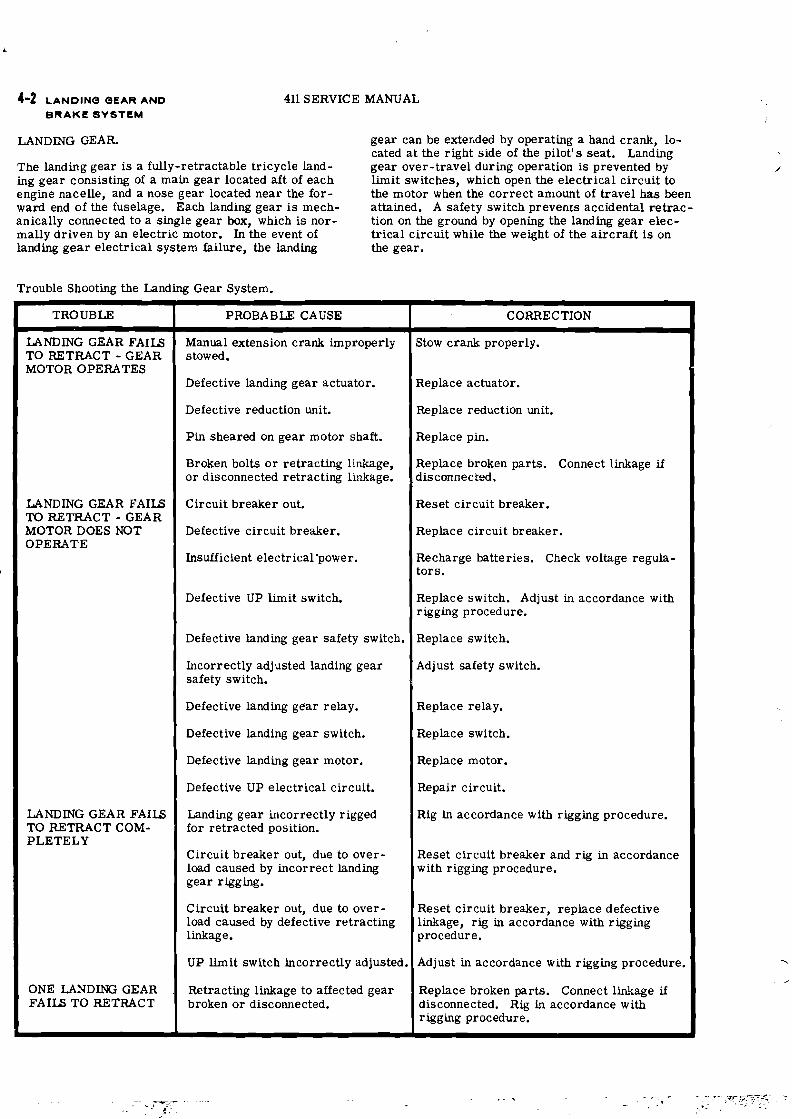
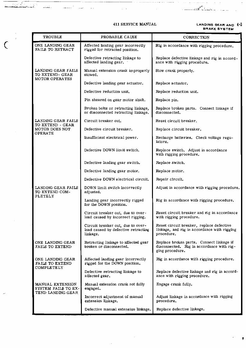
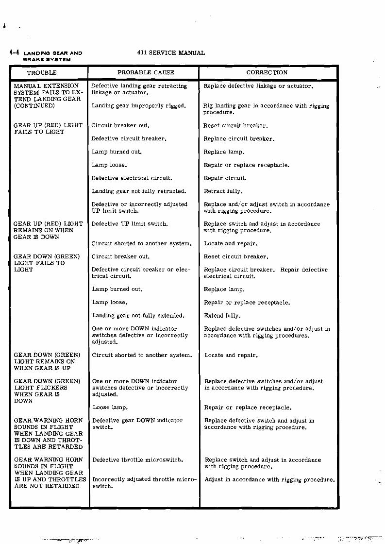
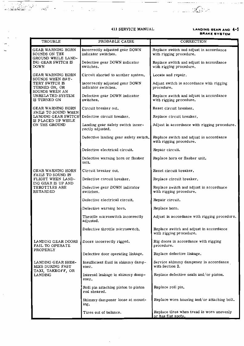
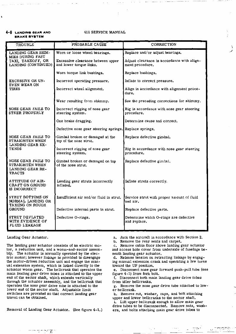
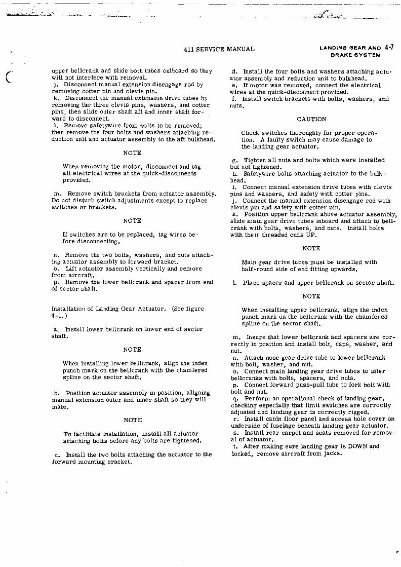
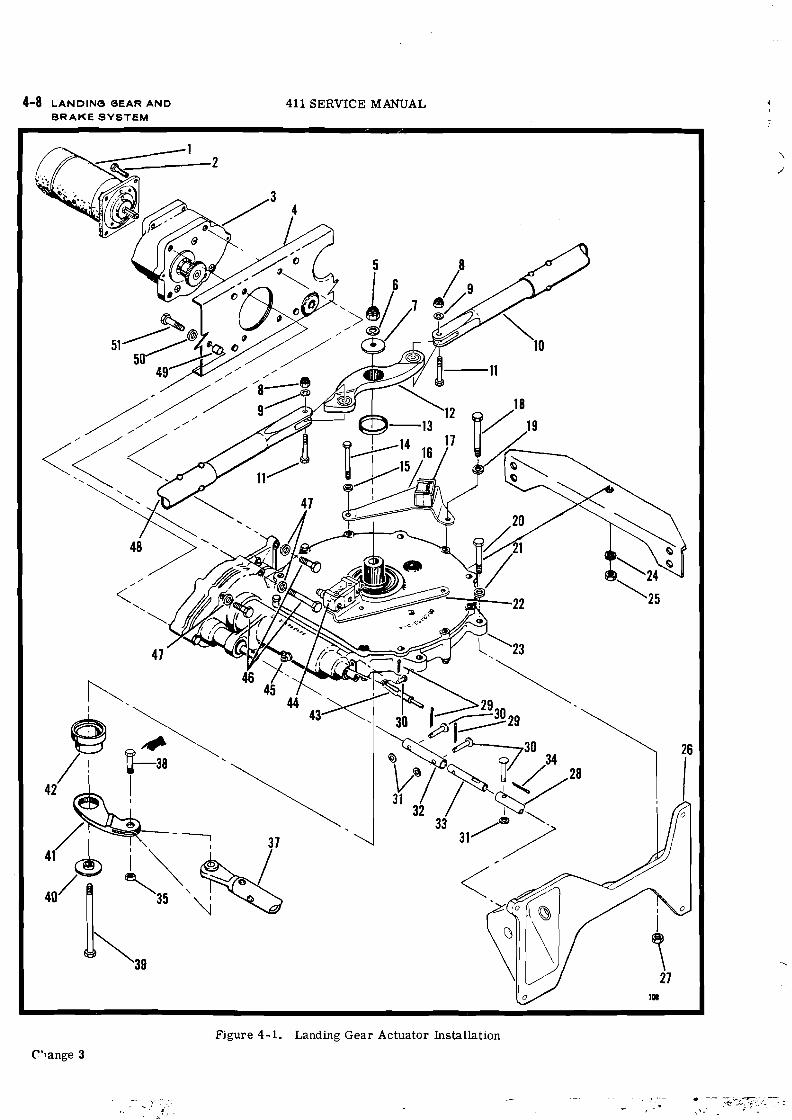
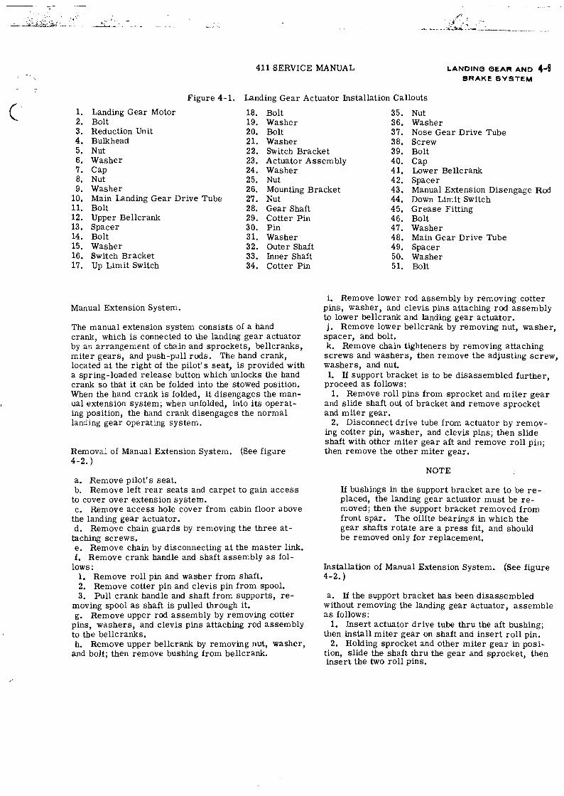
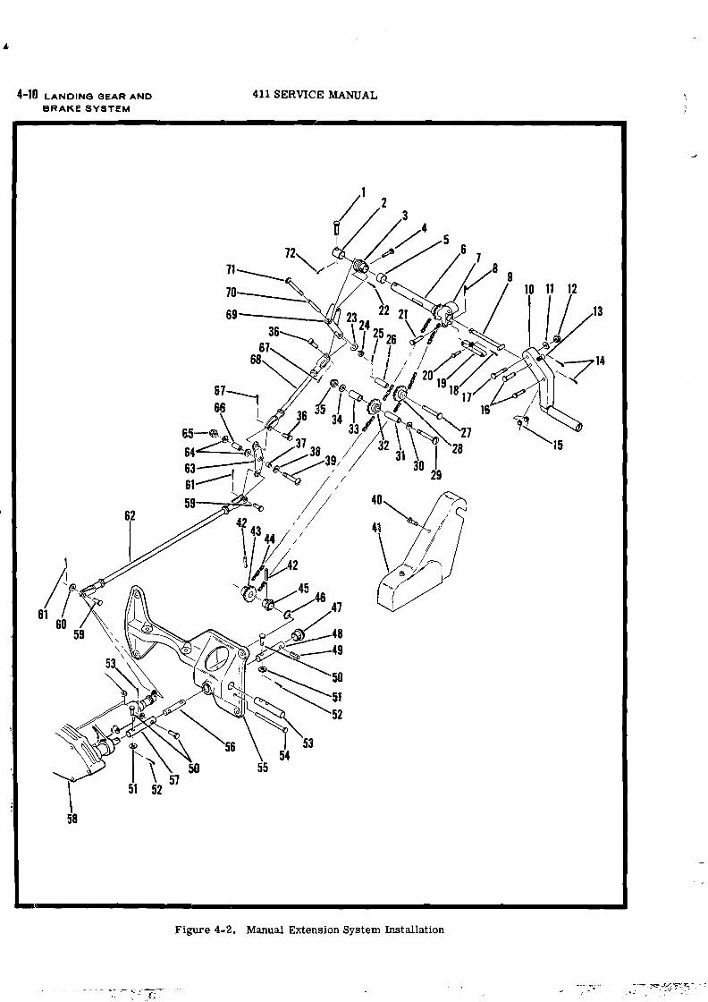
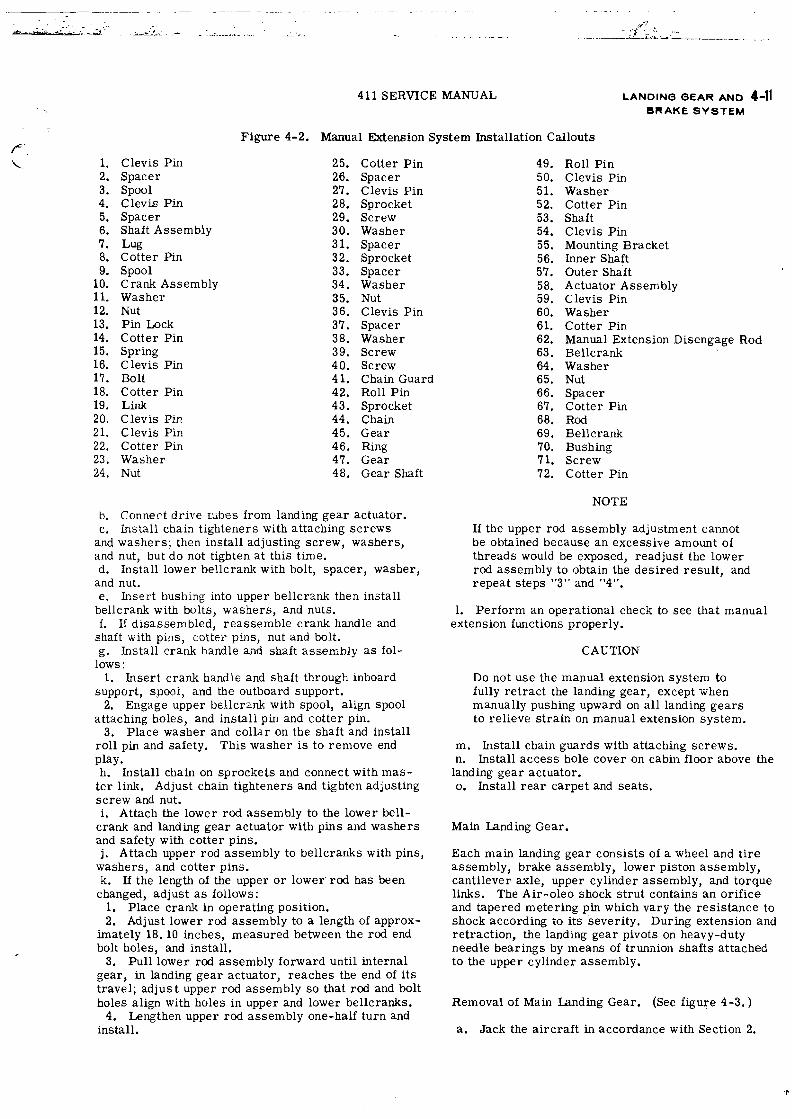
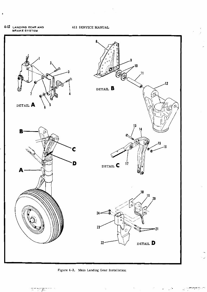
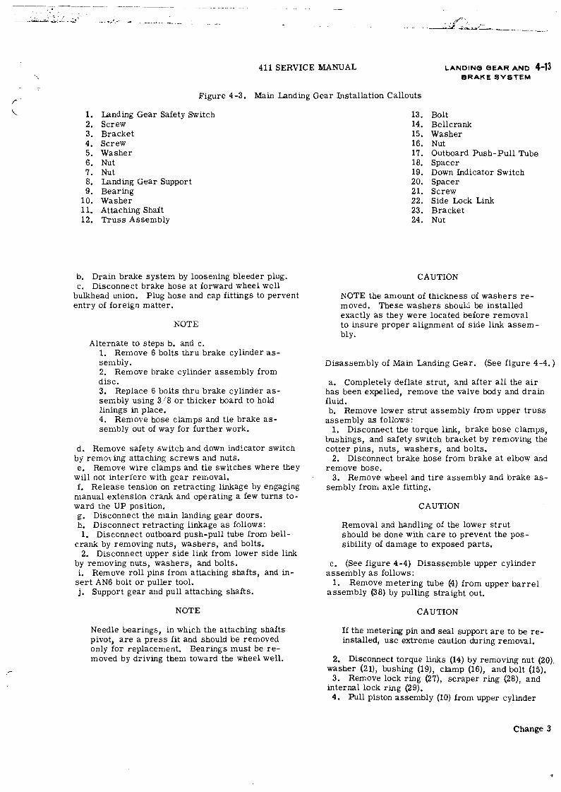
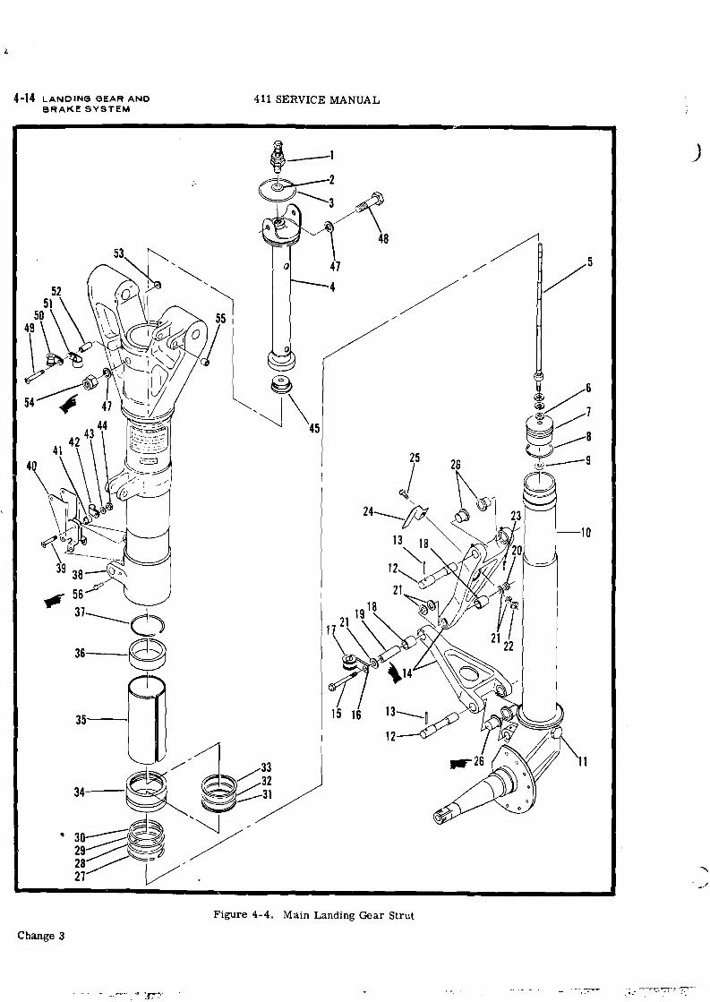
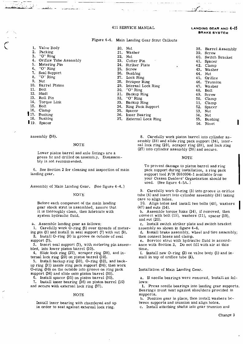
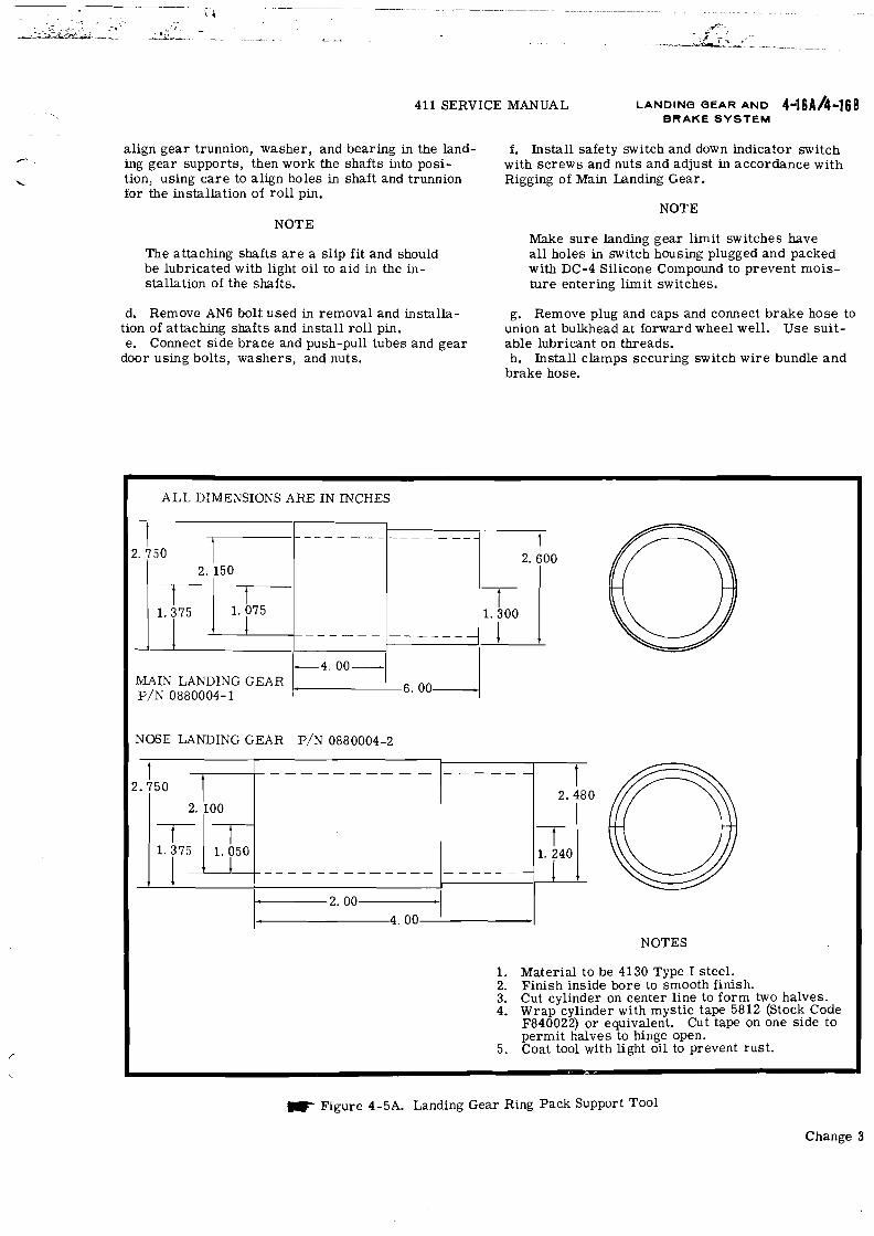
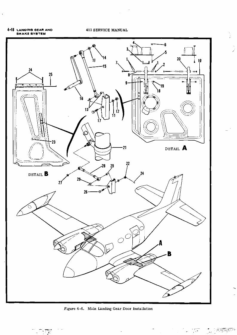
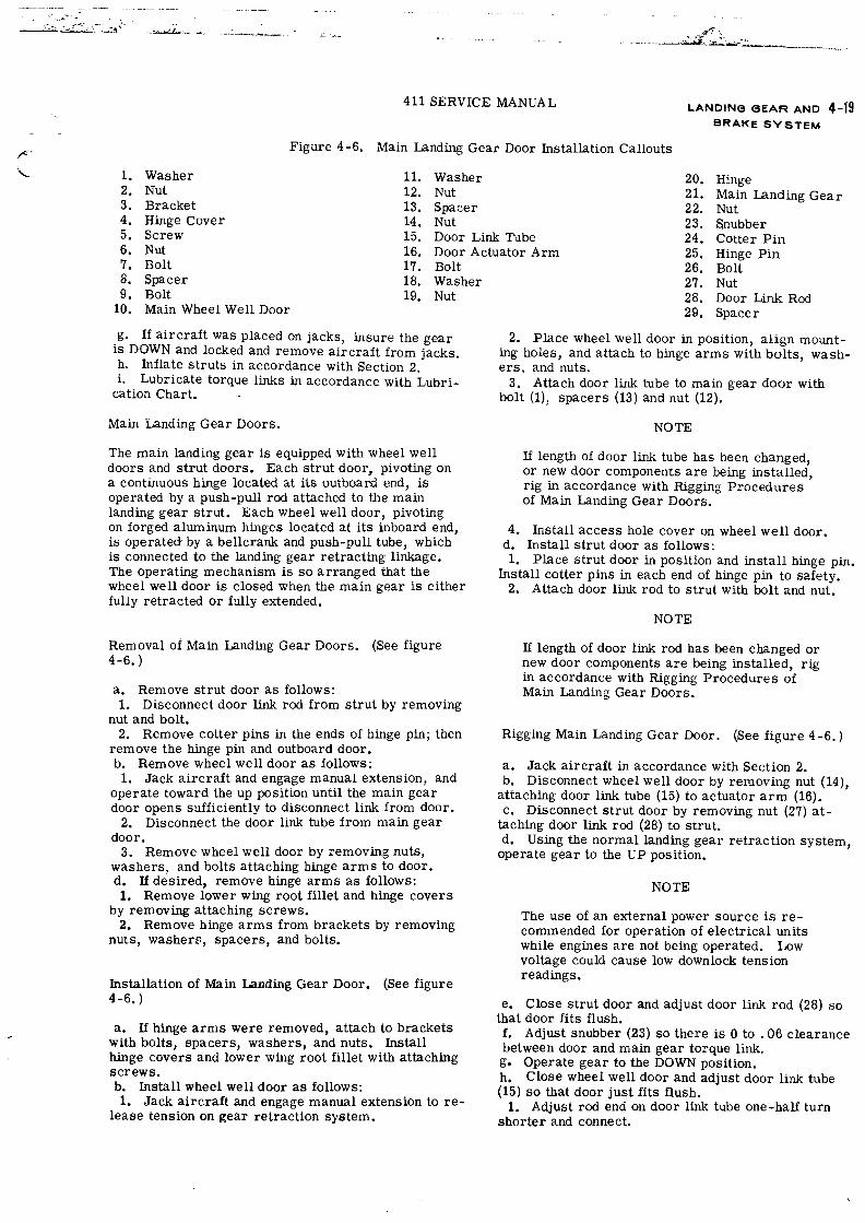
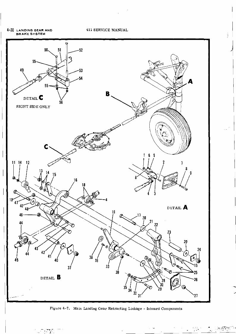
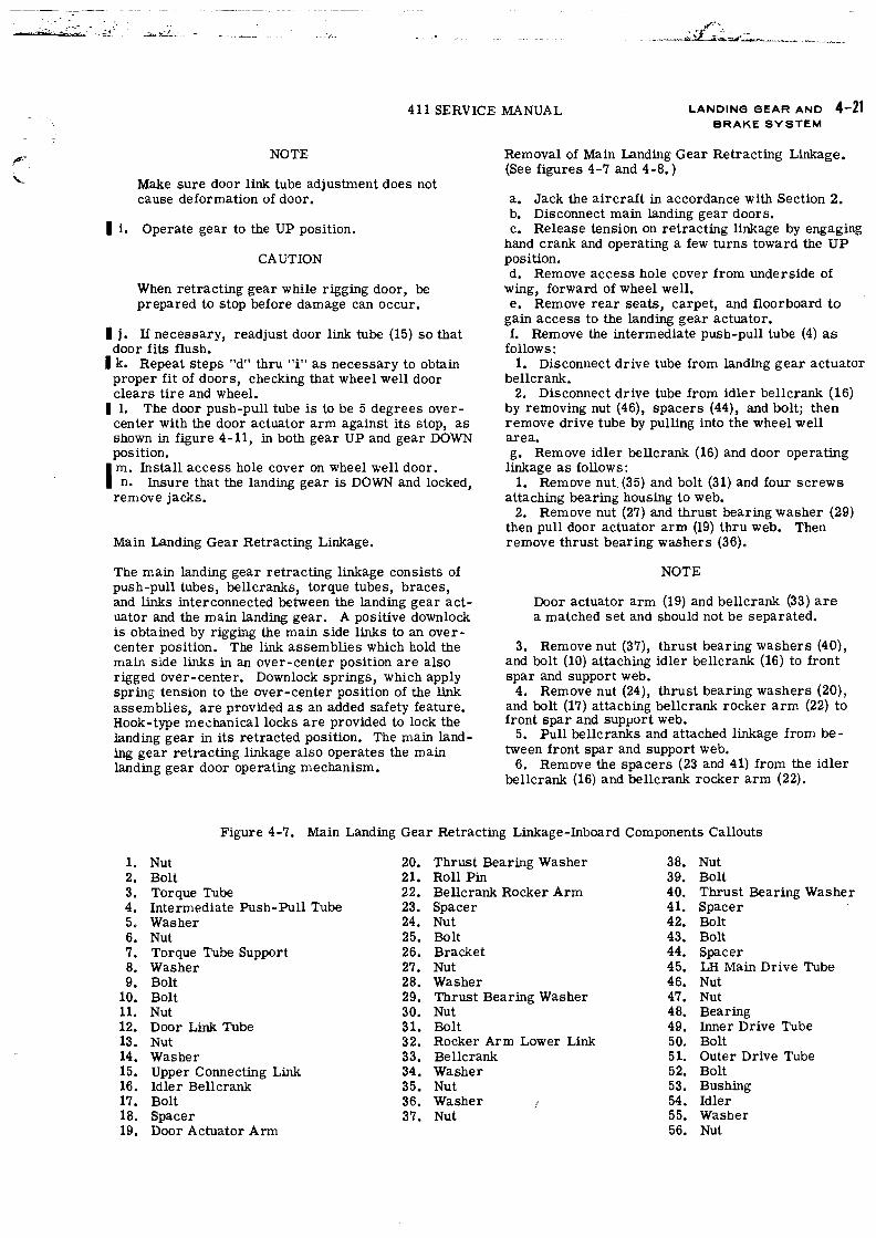
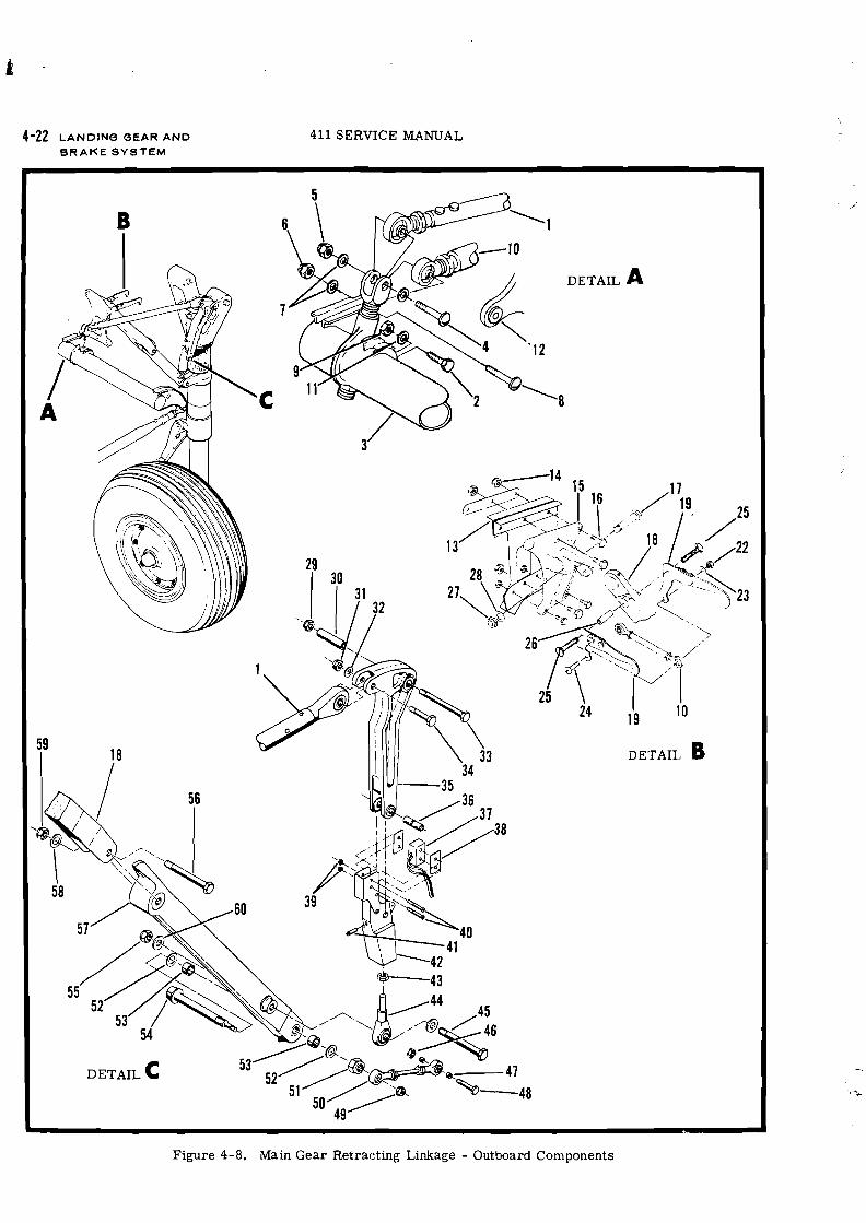
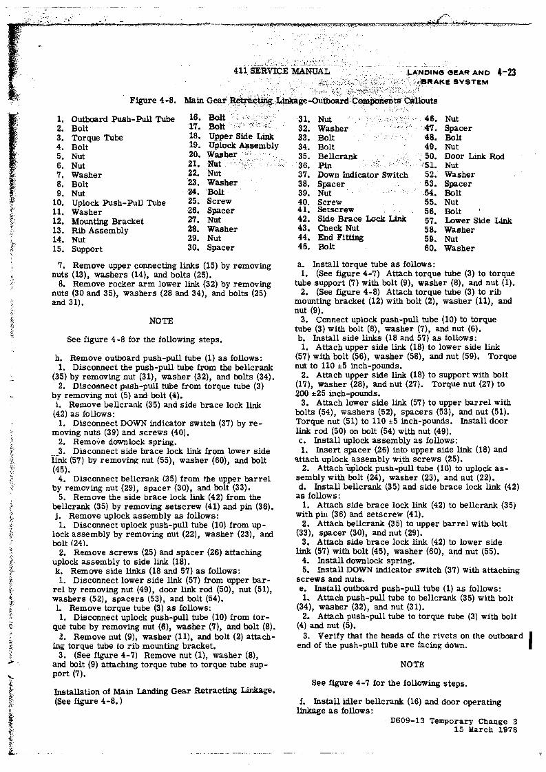
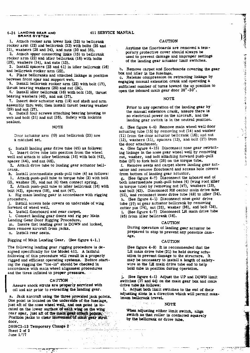
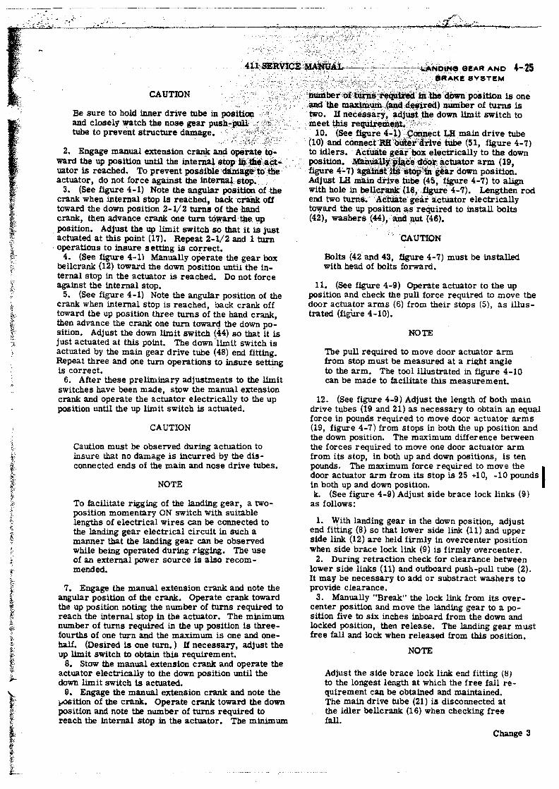
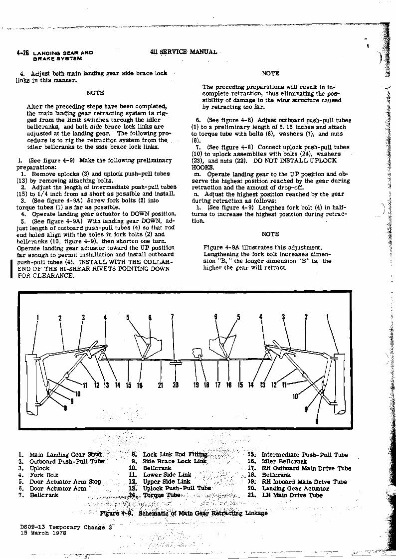
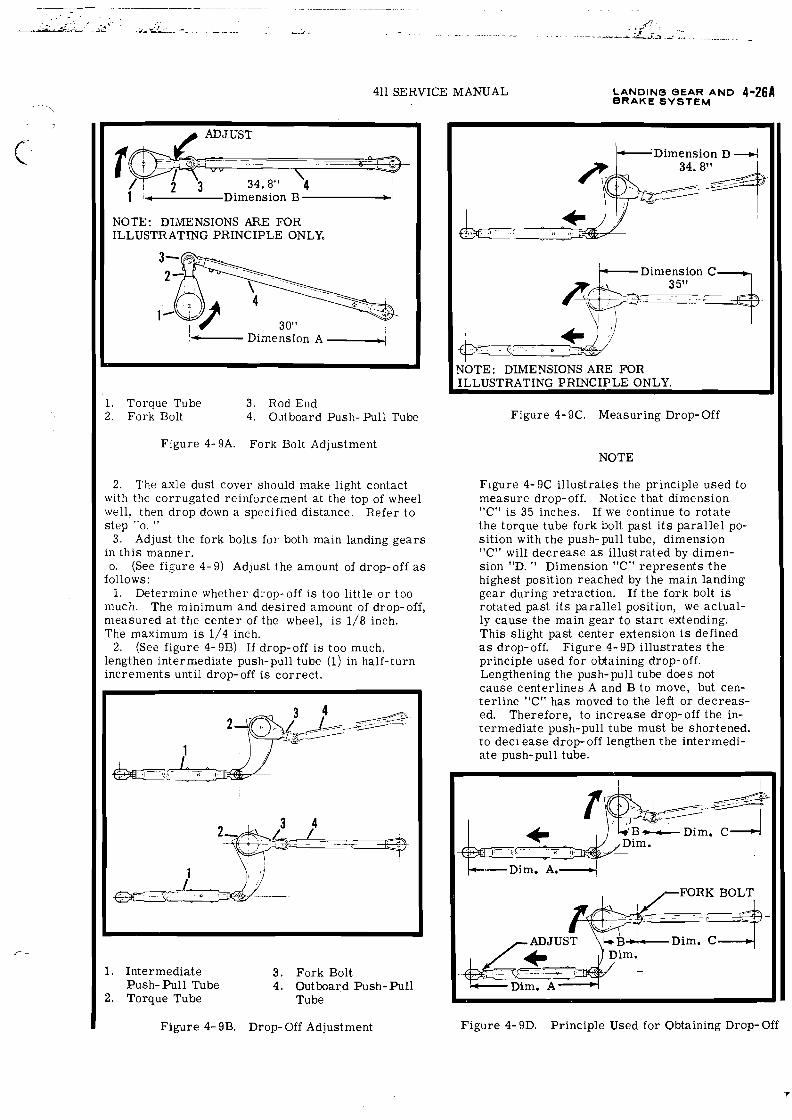
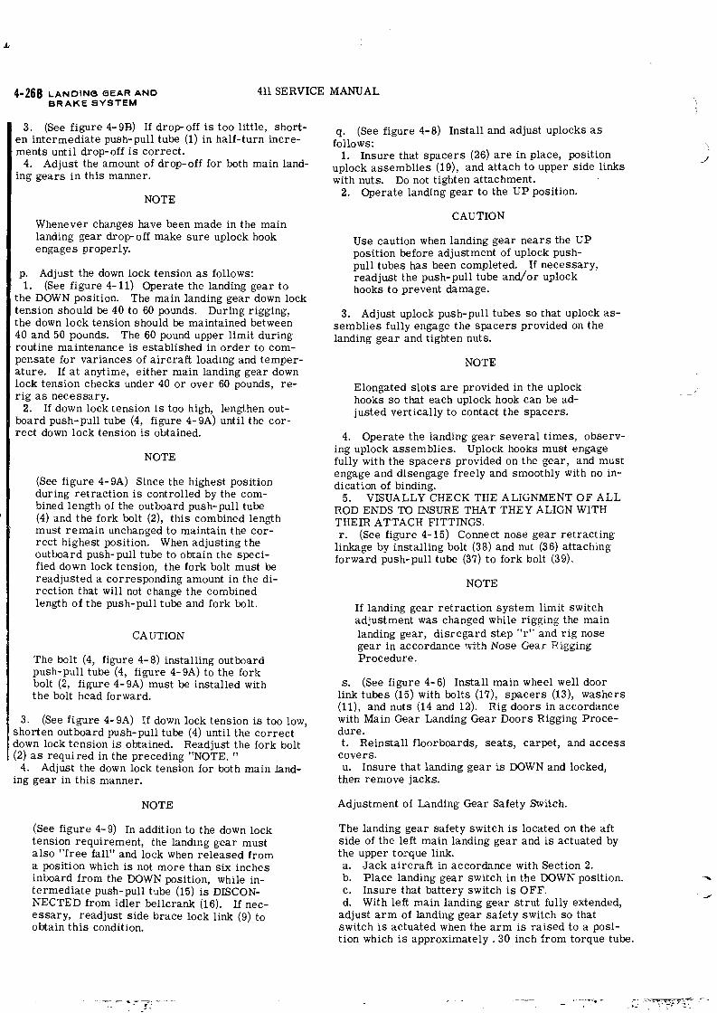
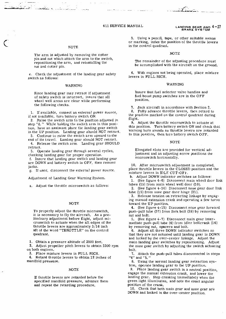
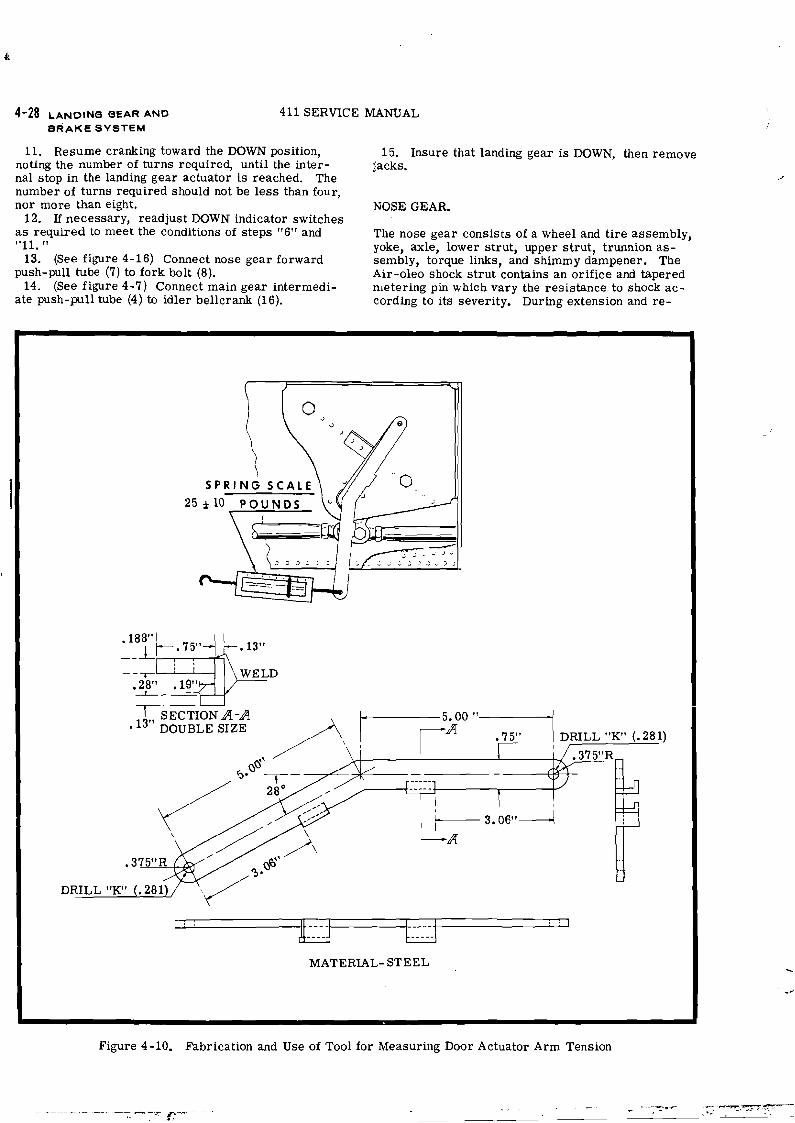
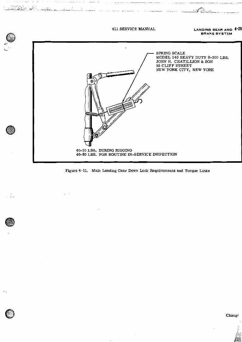
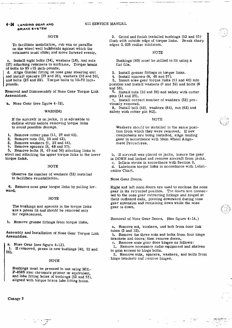
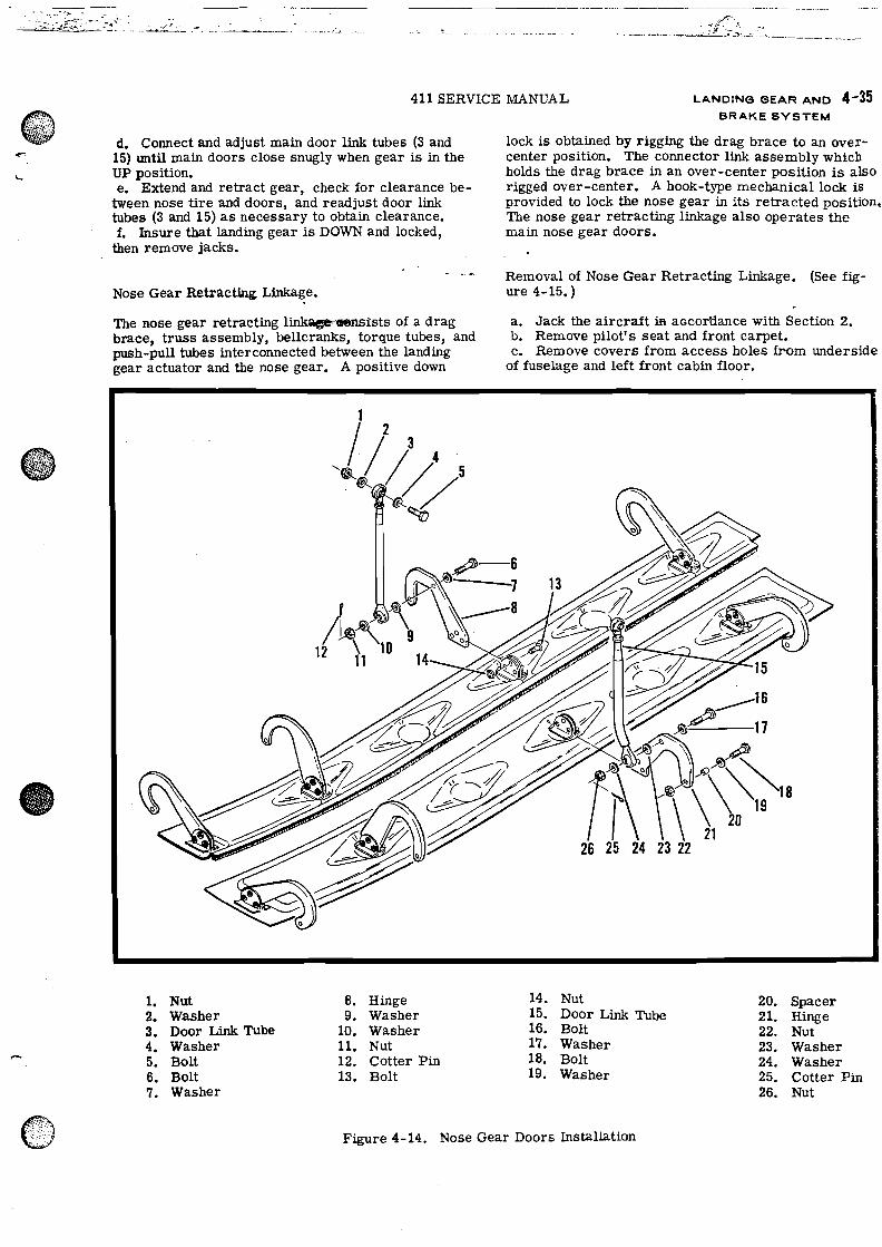
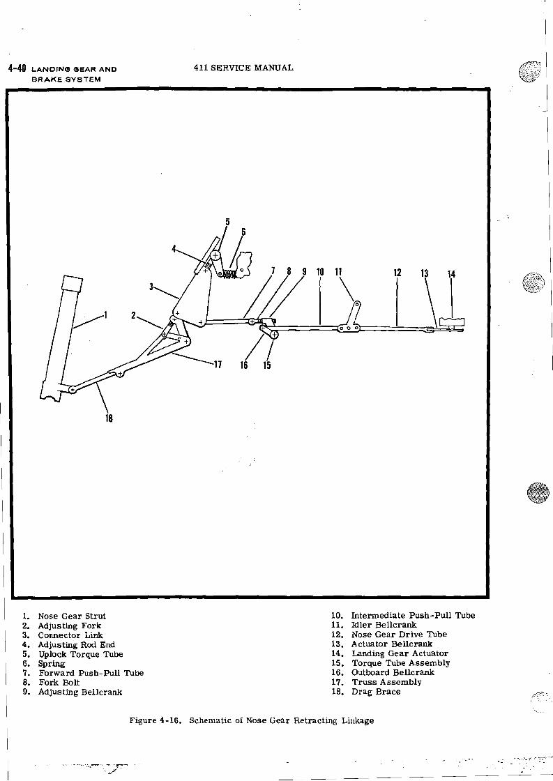
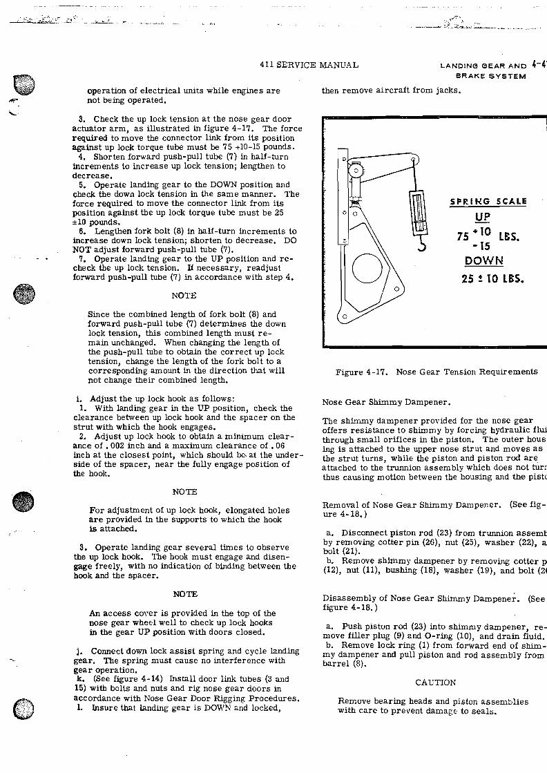
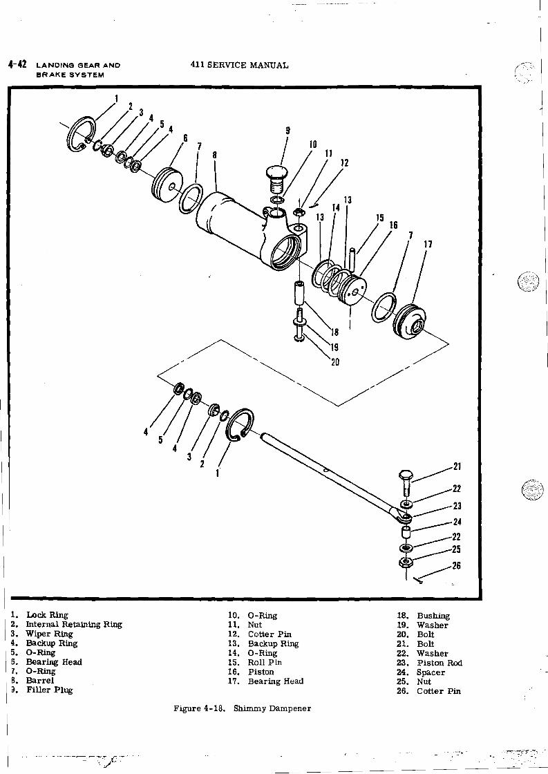
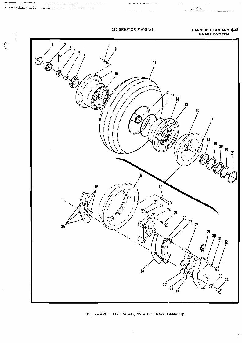
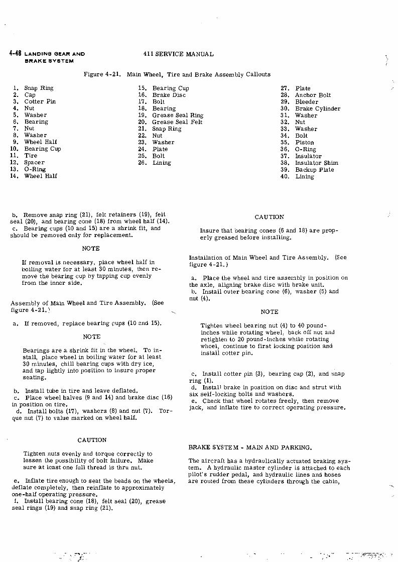
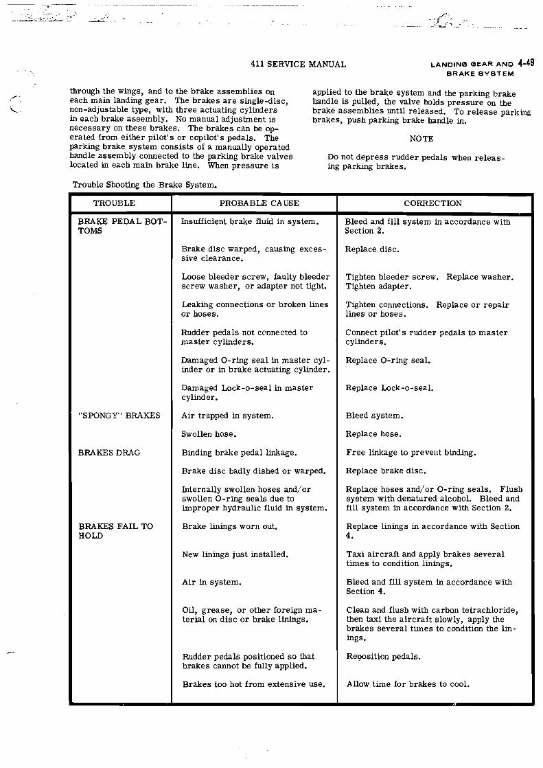
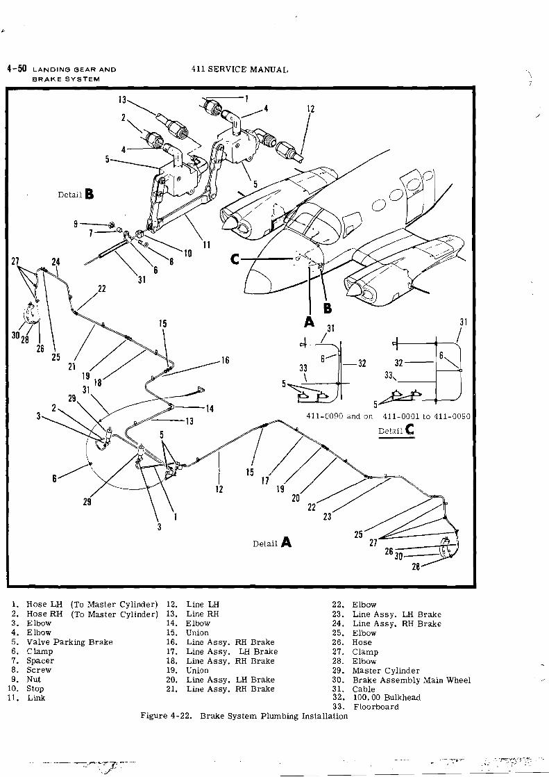
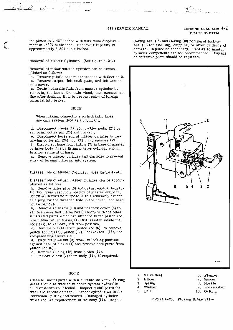
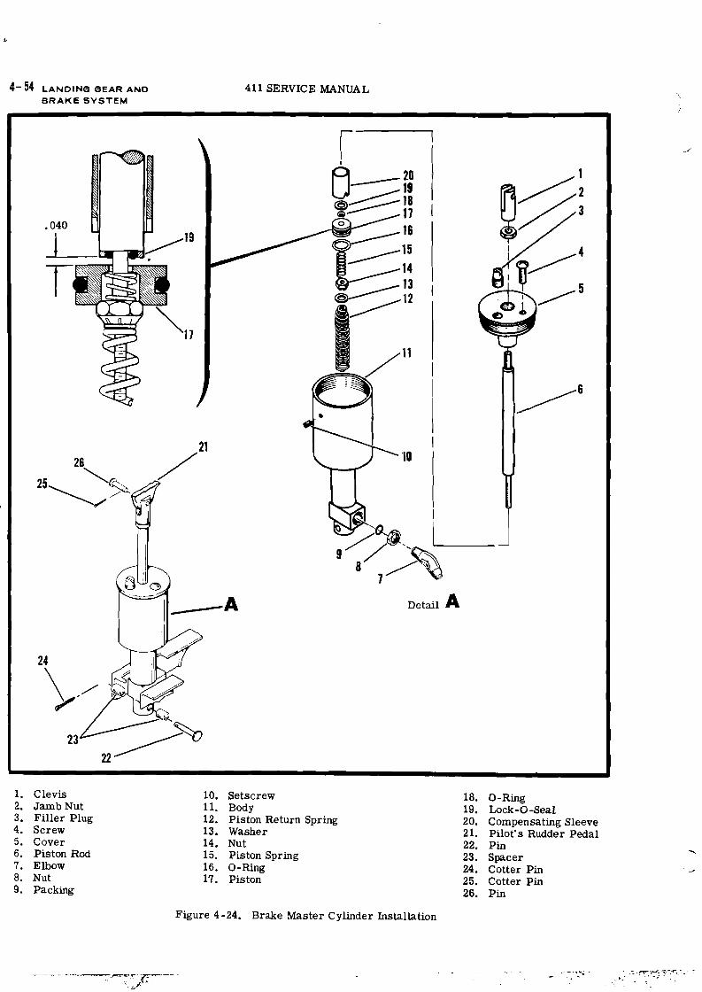
![Landing Gear Accessories - goldlinequalityparts.com€¦ · 12 Landing Gear Accessories Landing Gear Accessories 13 [254.0mm] 10.00" [254.0mm] 10.00" [111.3mm] 4.38" [304.8mm] 12.00"](https://static.documents.pub/doc/80x56/5f42201687106b11477aac9b/landing-gear-accessories-12-landing-gear-accessories-landing-gear-accessories.jpg)


![arXiv:1407.0927v1 [cs.SE] 3 Jul 2014Landing-Gear Extended Landing-Gear Retracted Landing-Gear Box Landing Wheel Door Figure 1: Landing Gear System such as airport runways [11]. Three](https://static.documents.pub/doc/80x56/5e9397289f16a23cdf089611/arxiv14070927v1-csse-3-jul-2014-landing-gear-extended-landing-gear-retracted.jpg)


