44
07 - Landing Gear RG May 2007 07-XLR Page 7-1 Landing Gear RG
07 - Landing Gear RG
May 2007 07-XLR Page 7-1
Landing Gear RG
07- Landing Gear RG
Page 7-2 07-XLR May 2007
○
○
○
○
○
○
○
○
○
○
○
○
○
This PageIntentionallyLeft Blank
07 - Landing Gear RG
May 2007 07-XLR Page 7-3
Contents7.0 - Chapter Preface ....................................................................................7-4
7.0.1 - Parts List ................................................................................................... 7-47.0.2 - Tools List .................................................................................................. 7-57.0.3 - Supplies List ............................................................................................. 7-67.0.4 - Glass List .................................................................................................. 7-67.0.5 - Process Overview .................................................................................... 7-6
7.1 - Nose Gear Door Installation ................................................................7-87.1.1 - Nose Gear Door Cutout ............................................................................ 7-8
7.2 - Nose Gear Installation ........................................................................7-127.2.1 - Nose Gear Bushings................................................................................ 7-127.2.2 - Overcenter Linkage ................................................................................. 7-147.2.3 - Sequence Valve ....................................................................................... 7-147.2.4 - Gas Spring .............................................................................................. 7-157.2.5 - Nose Gear Guides................................................................................... 7-16
7.3 - Main Gear Preparation .......................................................................7-197.3.1 - Gear Leg Preparation .............................................................................. 7-197.3.2 - Gear Leg Torsional Reinforcement ......................................................... 7-19
7.4 - Fuselage Preparation ..........................................................................7-207.4.1 - Gear leg cut out ....................................................................................... 7-207.4.2 - Drilling Holes for Main Gear Bushings .................................................. 7-207.4.3 Transverse Bulkhead Install ...................................................................... 7-21
7.5 - Installation of Main Gear Bushings ....................................................7-23
7.6 - Main Gear Pulley Installation .............................................................7-257.6.1 - Pulley Assembly ..................................................................................... 7-257.6.2 - Main Gear Overcenter Linkage and Sockets ........................................... 7-267.6.3 - Hydraulic Cylinder ................................................................................. 7-297.6.4 - Cables ..................................................................................................... 7-29
7.7 - Installing the Main Gear .....................................................................7-307.7.1 - Gear Legs................................................................................................ 7-307.7.2 - Brake Lines ............................................................................................. 7-307.7.3 - Main Gear Doors .................................................................................... 7-30
7.8 - Hydraulic System ...............................................................................7-347.8.1 - Hydraulic Power Pack and Nose Gear Door Cylinder ........................... 7-347.8.2 - Plumbing ................................................................................................. 7-357.8.3 - Pressure switch adjustment. .................................................................... 7-357.8.4 - Electrical ................................................................................................ 7-387.8.5 - Final System Adjustments ....................................................................... 7-39
7.9 - Emergency Extension .........................................................................7-417.8.1 - Basics ..................................................................................................... 7-417.8.2 - Nose Gear Safety Stick ........................................................................... 7-41
07- Landing Gear RG
Page 7-4 07-XLR May 2007
○
○
○
○
○
○
○
○
○
○
○
○
○
7.0 - Chapter Preface
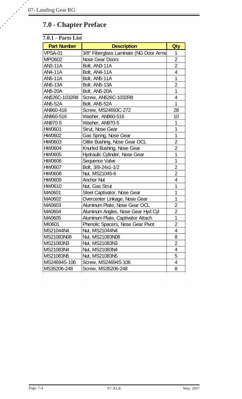
7.0.1 - Parts ListPart Number Description Qty
VPSA-01 3/8" Fiberglass Laminate (NG Door Arms 1MPO602 Nose Gear Doors 2AN3-11A Bolt, AN3-11A 2AN4-11A Bolt, AN4-11A 4AN5-11A Bolt, AN5-11A 1AN5-13A Bolt, AN5-13A 2AN5-20A Bolt, AN5-20A 1AN526C-1032R8 Screw, AN526C-1032R8 4AN5-52A Bolt, AN5-52A 1AN960-416 Screw, MS24693C-272 28AN960-516 Washer, AN960-516 10AN970-5 Washer, AN970-5 1HW0601 Strut, Nose Gear 1HW0602 Gas Spring, Nose Gear 1HW0603 Oilite Bushing, Nose Gear OCL 2HW0604 Knurled Bushing, Nose Gear 2HW0605 Hydraulic Cylinder, Nose Gear 1HW0606 Sequence Valve 1HW0607 Bolt, 3/8-24x1-1/2 2HW0608 Nut, MS21045-6 2HW0609 Anchor Nut 4HW0610 Nut, Gas Strut 1MA0601 Steel Captivator, Nose Gear 1MA0602 Overcenter Linkage, Nose Gear 1MA0603 Aluminum Plate, Nose Gear OCL 2MA0604 Aluminum Angles, Nose Gear Hyd Cyl 2MA0605 Aluminum Plate, Captivator Attach 1MI0601 Phenolic Spacers, Nose Gear Pivot 2MS21044N4 Nut, MS21044N4 4MS21083N08 Nut, MS21083N08 8MS21083N3 Nut, MS21083N3 2MS21083N4 Nut, MS21083N4 4MS21083N5 Nut, MS21083N5 5MS24694S-106 Screw, MS24694S-106 4MS35206-248 Screw, MS35206-248 8

07 - Landing Gear RG
May 2007 07-XLR Page 7-5
Part Number Description QtyMP0901 Main Gear Leg 1MP0902 Gear Saddle 2BUSH3/4 O.D. Bushing 3/4" O.D. 2KBUSH1 Knurrled Bushing 1" O.D. 4BOLT5/8-13x10 Main Gear Bolt, 5/8"-13 x 10" L #8 2WASH5/8 Main Gear Washer, 5/8" #8 4NUT5/8-13 Main Gear Locknut, 5/8"-13 2
MA0901 Nose Gear Fork 1KBUSH1 Knurrled Bushing 1" O.D. 2BOLT 7/16 -16x7" Nose Gear Bolt, 7/16"-16 x 7" #8 1AN960-716 Nose Gear Washer, AN960-716 2NUT 7/16"-16 Nose Gear Locknut, 7/16"-16 1NUT1/2-13 Nut, 1/2"-13 1MS21083N6 Nut, MS21083N6 2AN4-13A Bolt, AN4-13A 4AN970-4 Washer, AN970-4 4AN960-416 Washer, AN960-416 8MS21083N4 Nut, MS21083N4 4CAPSCR1/4-20x1 Cap Screw, 1/4"-20 x 1" 4TE0901 Cut Out Template 1
7.0.2 - Tools List
DescriptionHacksaw BladesDrill Bit, 1/4" LongHole Saw, 7/8"Jig or Band SawPlumb BobJig Saw1/4" Drill Bit 12" Long1" Hole Saw5/8" Hole Saw2" Hole Saw1/4x20 Tap

07- Landing Gear RG
Page 7-6 07-XLR May 2007
○
○
○
○
○
○
○
○
○
○
○
○
○
7.0.3 - Supplies ListDescription
EZ-PoxyMilled FiberBondoDuct Tape25" x 1/4" Threaded Rods ( 2 )5 Minute EpoxyVelociPoxy?
7.0.4 - Glass ListType Size Qty
BID 3" x Perimeter of Door 3BID 3" x 3" (Swing Arms) 16BID 3" x 4" (Swing Arm Tab) 32TRIAX 4"X11" 20TRIAX 4"X20" 16TRIAX 8"X7" 12TRIAX 4"X4" 8
7.0.5 - Process OverviewCompletion
DateMark Nose Gear DoorsRemove Foam From DoorsGlass Over DoorsCut Out DoorsMake Lip Around DoorsCut 4 Swing ArmsMount Swing ArmsCut 8 Swing Arm TabsMount Swing Arm TabsCut Notches in Gear Door LipAttach Gear Door Hardware
Prepare Keel (Chapter 10)Install Nose Gear Pivot HardpointsInstall Overcenter Aluminum PlatesInstall KeelAttach Captivator PlateInstall Sequence ValveInstall Gas Spring
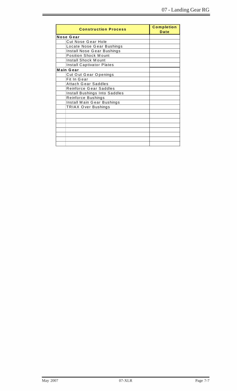
Construction Process
07 - Landing Gear RG
May 2007 07-XLR Page 7-7
C o m p let ionD ate
N ose G earC ut Nose G ear Ho leLoca te Nose G ear B ushingsIns ta ll Nose G ear BushingsPos it ion Shock M ountIns ta ll Shock M ountIns ta ll C ap tiva to r P la tes
M ain G earC ut O ut G ear O peningsF it In G earA ttach G ear Sadd lesR e info rce G ear Sadd lesIns ta ll Bushings Into Sadd lesR e info rce BushingsIns ta ll M a in G ear BushingsTR IAX O ver Bushings
C onstruct io n Process
07- Landing Gear RG
Page 7-8 07-XLR May 2007
○
○
○
○
○
○
○
○
○
○
○
○
○
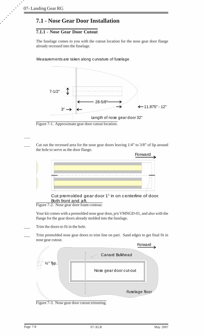
7.1 - Nose Gear Door Installation
7.1.1 - Nose Gear Door Cutout
The fuselage comes to you with the cutout location for the nose gear door flangealready recessed into the fuselage.
28-5/8“
3“
7-1/2“
Length of nose gear door 32“
11.875" - 12"
Measurements are taken along curvature of fuselage
Figure 7-1. Approximate gear door cutout location.
___
___ Cut out the recessed area for the nose gear doors leaving 1/4” to 3/8” of lip aroundthe hole to serve as the door flange.
Forward
Cut premolded gear door 1“ in on centerline of door.Both front and aft.
Figure 7-2. Nose gear door foam contour.
Your kit comes with a premolded nose gear door, p/n VMNGD-01, and also with theflange for the gear doors already molded into the fuselage.
___ Trim the doors to fit in the hole.
___ Trim premolded nose gear doors to trim line on part. Sand edges to get final fit innose gear cutout.
Canard Bulkhead
½" Typ.
Forward
Fuselage floor
Nose gear door cut-out
Figure 7-3. Nose gear door cutout trimming.
07 - Landing Gear RG
May 2007 07-XLR Page 7-9
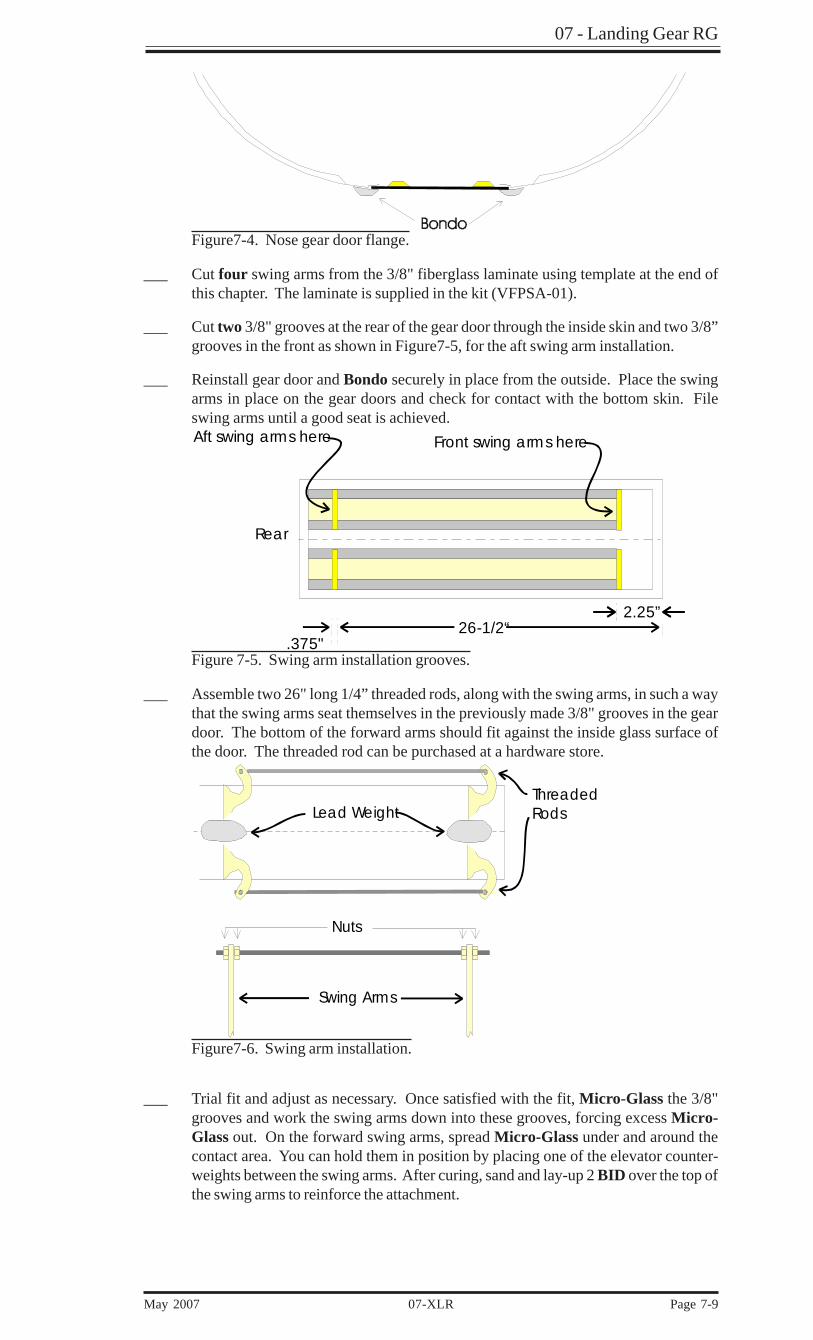
Figure7-4. Nose gear door flange.
___ Cut four swing arms from the 3/8" fiberglass laminate using template at the end ofthis chapter. The laminate is supplied in the kit (VFPSA-01).
___ Cut two 3/8" grooves at the rear of the gear door through the inside skin and two 3/8”grooves in the front as shown in Figure7-5, for the aft swing arm installation.
___ Reinstall gear door and Bondo securely in place from the outside. Place the swingarms in place on the gear doors and check for contact with the bottom skin. Fileswing arms until a good seat is achieved.
Rear
26-1/2“.375"
Aft swing arms here Front swing arms here
2.25”
Figure 7-5. Swing arm installation grooves.
___ Assemble two 26" long 1/4” threaded rods, along with the swing arms, in such a waythat the swing arms seat themselves in the previously made 3/8" grooves in the geardoor. The bottom of the forward arms should fit against the inside glass surface ofthe door. The threaded rod can be purchased at a hardware store.
Lead WeightThreadedRods
Swing Arms
Nuts
Figure7-6. Swing arm installation.
___ Trial fit and adjust as necessary. Once satisfied with the fit, Micro-Glass the 3/8"grooves and work the swing arms down into these grooves, forcing excess Micro-Glass out. On the forward swing arms, spread Micro-Glass under and around thecontact area. You can hold them in position by placing one of the elevator counter-weights between the swing arms. After curing, sand and lay-up 2 BID over the top ofthe swing arms to reinforce the attachment.

07- Landing Gear RG
Page 7-10 07-XLR May 2007
○
○
○
○
○
○
○
○
○
○
○
○
○
___ Using templates at the end of this chapter as a guide, make eight fiberglass tabs.These tabs are used to hold the swing arms to the fuselage and can be made from twolayers of cured TRIAX, 5 plies BID or trimmings from any lay-up that is between 1/16" and 1/8" thick.
___ Trim the tabs until they will fit in all eight positions and attach the tabs to the respec-tive swing arms with AN bolts, washers and nuts. See Figure 7-7.
Canard Bulkhead
Swing Arm
Tabs
Washers (4)
Washers (4)AN4-11A Bolts
Swing ArmTabs
AN960-416MS21083N4
Figure 7-7. Swing arm installation.
___ The tabs should have a slight amount of clearance between the tab and fuselage toprevent binding. Use 5 Minute Epoxy to attach the tabs to the fuselage and allow tocure for at least 30 minutes before moving.
___ Measure gear door both front and aft and find the center. Draw a line connectingthese two point and cut on this line.
___ Remove bolts and washers and hacksaw the gear door into two halves using the oneinch cuts you have made in the nosegear doors.
___ After completing cut, break loose from Bondo and remove the gear doors.
___ Glass the tabs onto the fuselage using two plies BID on each side.
Figure 7-8. Swing arm tab lay-ups.
___ After cure, drill out 1/4” holes in the tabs.
Figure 7-9. Notches in nose gear door cutout to clear swing arms.
___ It will be necessary to do some filing to keep the gear doors from catching on thefuselage.

07 - Landing Gear RG
May 2007 07-XLR Page 7-11
Figure 7-10. Bevel nose gear door edges to prevent interference.
___ The final assembly will look as shown in Figure 7-11.
TabsSwing Arm
1 Washer each side
Figure 7-11. Nose gear door hinge detail.

07- Landing Gear RG
Page 7-12 07-XLR May 2007
○
○
○
○
○
○
○
○
○
○
○
○
○
7.2 - Nose Gear Installation
7.2.1 - Nose Gear Bushings
Figure 7-12 is an overview of the nose gear installation. Plywood inserts are in-stalled in the keel as described in Chapter 6. Before continuing you should pre-pare the keel as described in that chapter. Trial fit the nose gear, shock, and linkageto make sure everything aligns properly.
Stee
l Ca
ptiv
ato
rM
A060
1
Plyw
ood
inse
rt
App
roxim
ate
ly 2
9-1/
4“Fr
om C
ana
rd B
ulkh
ead
17-7
/8" F
rom
kee
lfla
nge
aft
fac
e9.
75"
No
se g
ear
Shoc
k st
rut
HW
0601
Ove
rce
nte
r lin
kag
eM
A060
2
Hyd
raul
ic c
ylin
der
HW
0605
Ga
s sp
ring
VNG
GS-
01(4
) MS2
4694
S-10
6 sc
rew
(2) M
S210
44N
4 nu
ts(4
) AN
960-
416
wa
she
rs(2
) VAA
NG
C-0
1 Al
umin
um A
ngle
s
Phen
olic
Sp
ace
rsM
I060
1
Ove
r Cen
ter L
inka
ge
Bea
ring
Pla
te -
MA0
603
(VN
GO
CBP
-01)
(2) A
N3-
7A B
olts
(2) M
S210
42-3
Lo
cknu
ts(2
) AN
960-
10 W
ash
ers
AN5-
52A
AN96
0-51
6AM
S210
83N
5
Fina
l Pos
ition
1/8
"-1/4
" a
bov
e h
orizo
nta
l
AN5-
11A
AN96
0-51
6AM
S210
83N
5
AN5-
13A
AN96
0-51
6M
S210
83N
5
AN5-
20A
AN96
0-51
6M
S210
83N
5
Ce
nte
r Ke
elVA
SMS-
01O
verc
ent
er S
top
Mic
rosw
itch
(2)A
N97
0-6
Fron
t (2)
MS2
1083
N4
thin
nut
s
Not
e: Y
ou m
ay
have
to g
rind
fro
nt s
cre
ws
toa
llow
cle
ara
nce
for
cylin
der
.VASN
GC
-01
- Sp
ac
er/R
am
Tra
vel L
imite
r (C
ut to
leng
th a
s re
qui
red
)
Ang
le b
rack
etIs
cut t
o sh
ape
To a
llow
for
Ram
trav
el
Figure 7-12. Nose gear actuator assembly.
07 - Landing Gear RG
May 2007 07-XLR Page 7-13
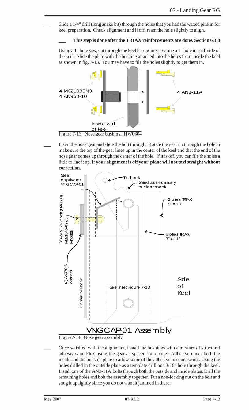
___ Slide a 1/4” drill (long snake bit) through the holes that you had the waxed pins in forkeel preparation. Check alignment and if off, ream the hole slightly to align.
___ This step is done after the TRIAX reinforcements are done. Section 6.3.8
Using a 1" hole saw, cut through the keel hardpoints creating a 1" hole in each side ofthe keel. Slide the plate with the bushing attached into the holes from inside the keelas shown in fig. 7-13. You may have to file the holes slightly to get them in.
4 AN3-11A4 MS21083N34 AN960-10
Inside wall of keel
Figure 7-13. Nose gear bushing. HW0604
___ Insert the nose gear and slide the bolt through. Rotate the gear up through the hole tomake sure the top of the gear lines up in the center of the keel and that the end of thenose gear comes up through the center of the hole. If it is off, you can file the holes alittle to line it up. If your alignment is off your plane will not taxi straight withoutcorrection.
To shockGrind as necessaryto clear shock
2 plies TRIAX9" x 13"
6 plies TRIAX3" x 11"
SteelcaptivatorVNGCAP-01
Cana
rd b
ulkh
ead
(2) A
N97
0-6
wash
ers"
3 /8-
24 x
1-1
/2" b
olt
(HW
060 8
)M
S210
45-6
nu t
MA 0
605
SideofKeel
See Inset Figure 7-13
VNGCAP-01 AssemblyFigure7-14. Nose gear assembly.
___ Once satisfied with the alignment, install the bushings with a mixture of structuraladhesive and Flox using the gear as spacer. Put enough Adhesive under both theinside and the out side plate to allow some of the adhesive to squeeze out. Using theholes drilled in the outside plate as a template drill one 3/16” hole through the keel.Install one of the AN3-11A bolts through both the outside and inside plates. Drill theremaining holes and bolt the assembly together. Put a non-locking nut on the bolt andsnug it up lightly since you do not want it jammed in there.
07- Landing Gear RG
Page 7-14 07-XLR May 2007
○
○
○
○
○
○
○
○
○
○
○
○
○
The other predrilled holes in the keel need to be opened back up since the hardpointsthat were installed would have covered them.
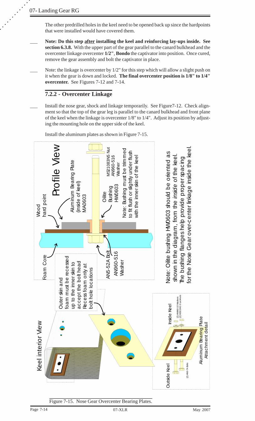
___ Note: Do this step after installing the keel and reinforcing lay-ups inside. Seesection 6.3.8. With the upper part of the gear parallel to the canard bulkhead and theovercenter linkage overcenter 1/2", Bondo the captivator into position. Once cured,remove the gear assembly and bolt the captivator in place.
___ Note: the linkage is overcenter by 1/2" for this step which will allow a slight push onit when the gear is down and locked. The final overcenter position is 1/8" to 1/4"overcenter. See Figures 7-12 and 7-14.
7.2.2 - Overcenter Linkage
___ Install the nose gear, shock and linkage temporarily. See Figure7-12. Check align-ment so that the top of the gear leg is parallel to the canard bulkhead and front planeof the keel when the linkage is overcenter 1/8" to 1/4". Adjust its position by adjust-ing the mounting hole on the upper side of the keel.
Install the aluminum plates as shown in Figure 7-15.
Oilit
e
Bush
ing
HW
0603
Alu
min
um B
earin
g P
late
(in
side
of k
eel)
MA
0603
No
te: B
ushi
ng m
ust b
e tri
mm
ed
to fi
t flu
sh o
r slig
htly
und
er fl
ush
with
the
inne
r skin
of t
he k
eel
Woo
d
hard
po
int
AN
5-52
A Bo
lt
Pro
file
Vie
wFo
am
Co
re
AN96
0-51
6W
ash
er
Out
er s
kin
and
fo
am
mus
t be
rece
sse
dup
to th
e in
ner s
kin
toa
cce
pt t
he b
olt
hea
dRe
ce
ss fo
am
onl
y a
t b
olt
hole
loca
tions
Kee
l int
erio
r Vie
w
Alu
min
um B
ea
ring
Pla
teAt
tac
hmen
t d
eta
ilInsid
e Ke
elO
utsid
e K
eel
(2) A
N3-
7A B
olts
(2) A
N96
0-10
Wa
sher
s(2
) MS2
1042
-3 L
ockn
uts
No
te: O
ilite
bus
hing
HW
0603
sho
uld
be
orie
nted
as
sho
wn
in th
e d
iag
ram
, fro
m th
e
of t
he k
eel
.Th
e b
ushi
ng fl
ang
es h
elp
pro
vid
e p
rop
er s
pa
cin
g
for t
he N
ose
Ge
ar o
ver-c
ent
er li
nka
ge
insid
e th
e k
ee
l.
insid
e
MS2
1083
N5
Nut
AN96
0-51
6W
ash
er
Figure 7-15. Nose Gear Overcenter Bearing Plates.
07 - Landing Gear RG
May 2007 07-XLR Page 7-15
Keel sides
Sequence Valve
(2) AN 3-11A
AN 816-4D
(2) AN 3-5A
Cutout forbracket
Figure 7-16 Installation of sequence valve
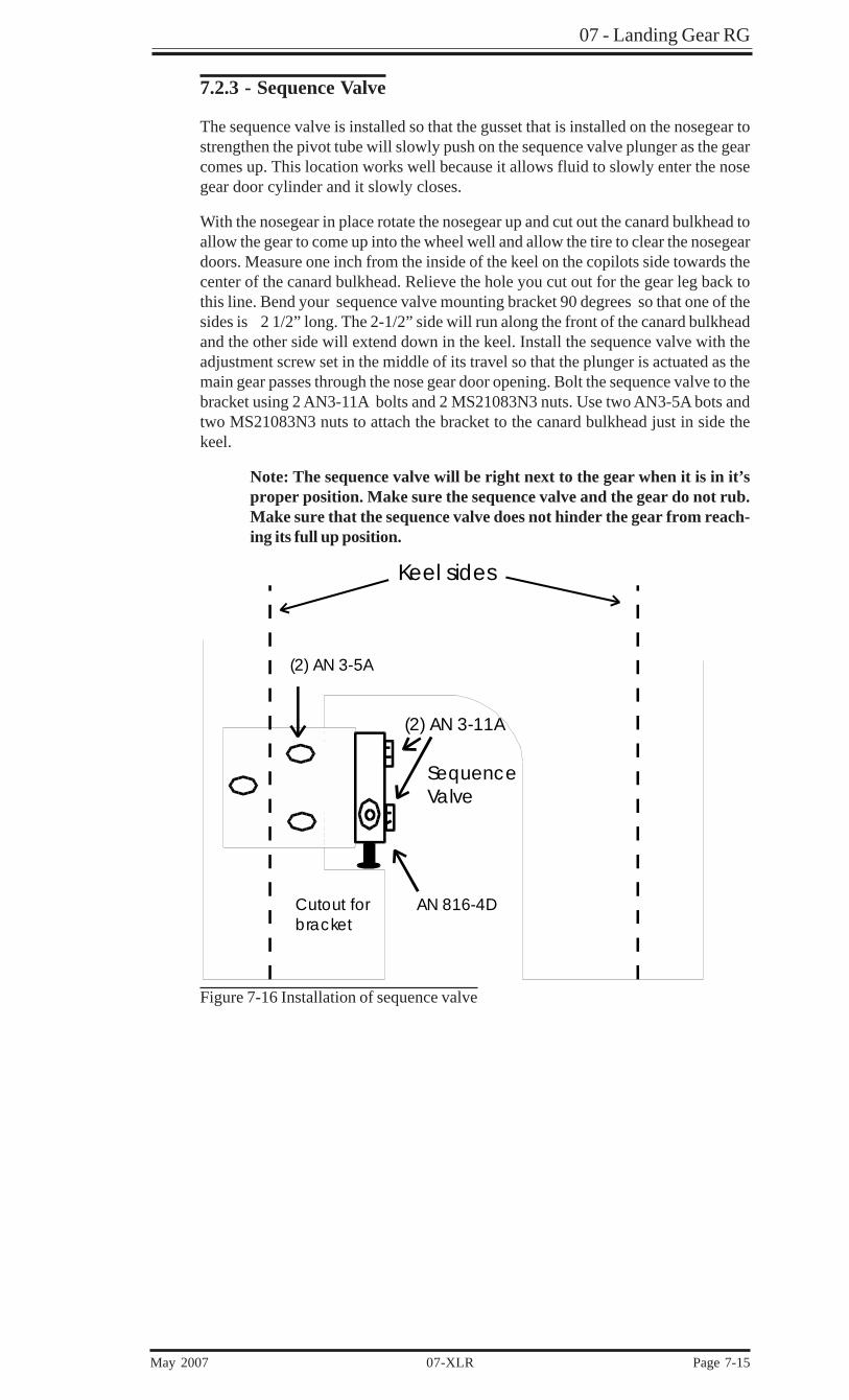
7.2.3 - Sequence Valve
The sequence valve is installed so that the gusset that is installed on the nosegear tostrengthen the pivot tube will slowly push on the sequence valve plunger as the gearcomes up. This location works well because it allows fluid to slowly enter the nosegear door cylinder and it slowly closes.
With the nosegear in place rotate the nosegear up and cut out the canard bulkhead toallow the gear to come up into the wheel well and allow the tire to clear the nosegeardoors. Measure one inch from the inside of the keel on the copilots side towards thecenter of the canard bulkhead. Relieve the hole you cut out for the gear leg back tothis line. Bend your sequence valve mounting bracket 90 degrees so that one of thesides is 2 1/2” long. The 2-1/2” side will run along the front of the canard bulkheadand the other side will extend down in the keel. Install the sequence valve with theadjustment screw set in the middle of its travel so that the plunger is actuated as themain gear passes through the nose gear door opening. Bolt the sequence valve to thebracket using 2 AN3-11A bolts and 2 MS21083N3 nuts. Use two AN3-5A bots andtwo MS21083N3 nuts to attach the bracket to the canard bulkhead just in side thekeel.
Note: The sequence valve will be right next to the gear when it is in it’sproper position. Make sure the sequence valve and the gear do not rub.Make sure that the sequence valve does not hinder the gear from reach-ing its full up position.
07- Landing Gear RG
Page 7-16 07-XLR May 2007
○
○
○
○
○
○
○
○
○
○
○
○
○
Side of keel
AN970-6 Washer
Special 5/16-18 nutHW0610
4 plies BID
Plywood hardpoint
Bottom Portion
Top Portion
Gussetted gas-spring arm onOvercenter linkage
Ball-end
5/16”-18 SAE Nylock Nut5/16” Washer - AN960-16
VNGGS-01 Assembly: Nose Gear Gas Spring
RetensionClip
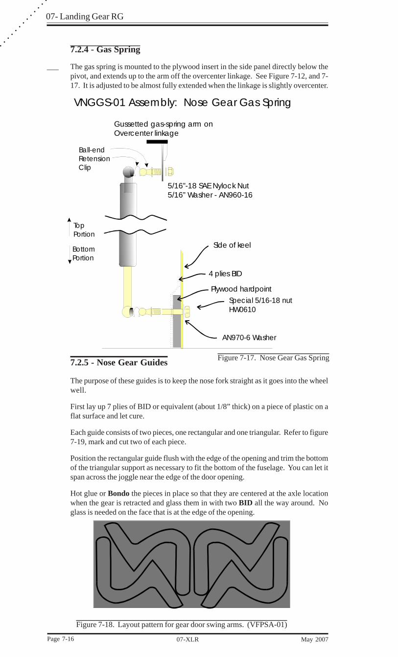
7.2.5 - Nose Gear Guides
The purpose of these guides is to keep the nose fork straight as it goes into the wheelwell.
First lay up 7 plies of BID or equivalent (about 1/8” thick) on a piece of plastic on aflat surface and let cure.
Each guide consists of two pieces, one rectangular and one triangular. Refer to figure7-19, mark and cut two of each piece.
Position the rectangular guide flush with the edge of the opening and trim the bottomof the triangular support as necessary to fit the bottom of the fuselage. You can let itspan across the joggle near the edge of the door opening.
Hot glue or Bondo the pieces in place so that they are centered at the axle locationwhen the gear is retracted and glass them in with two BID all the way around. Noglass is needed on the face that is at the edge of the opening.
7.2.4 - Gas Spring
___ The gas spring is mounted to the plywood insert in the side panel directly below thepivot, and extends up to the arm off the overcenter linkage. See Figure 7-12, and 7-17. It is adjusted to be almost fully extended when the linkage is slightly overcenter.
Figure 7-18. Layout pattern for gear door swing arms. (VFPSA-01)
Figure 7-17. Nose Gear Gas Spring
07 - Landing Gear RG
May 2007 07-XLR Page 7-17
TOP VIEW
BOTTOM VIEW
Gear Opening
3“
3“
9“
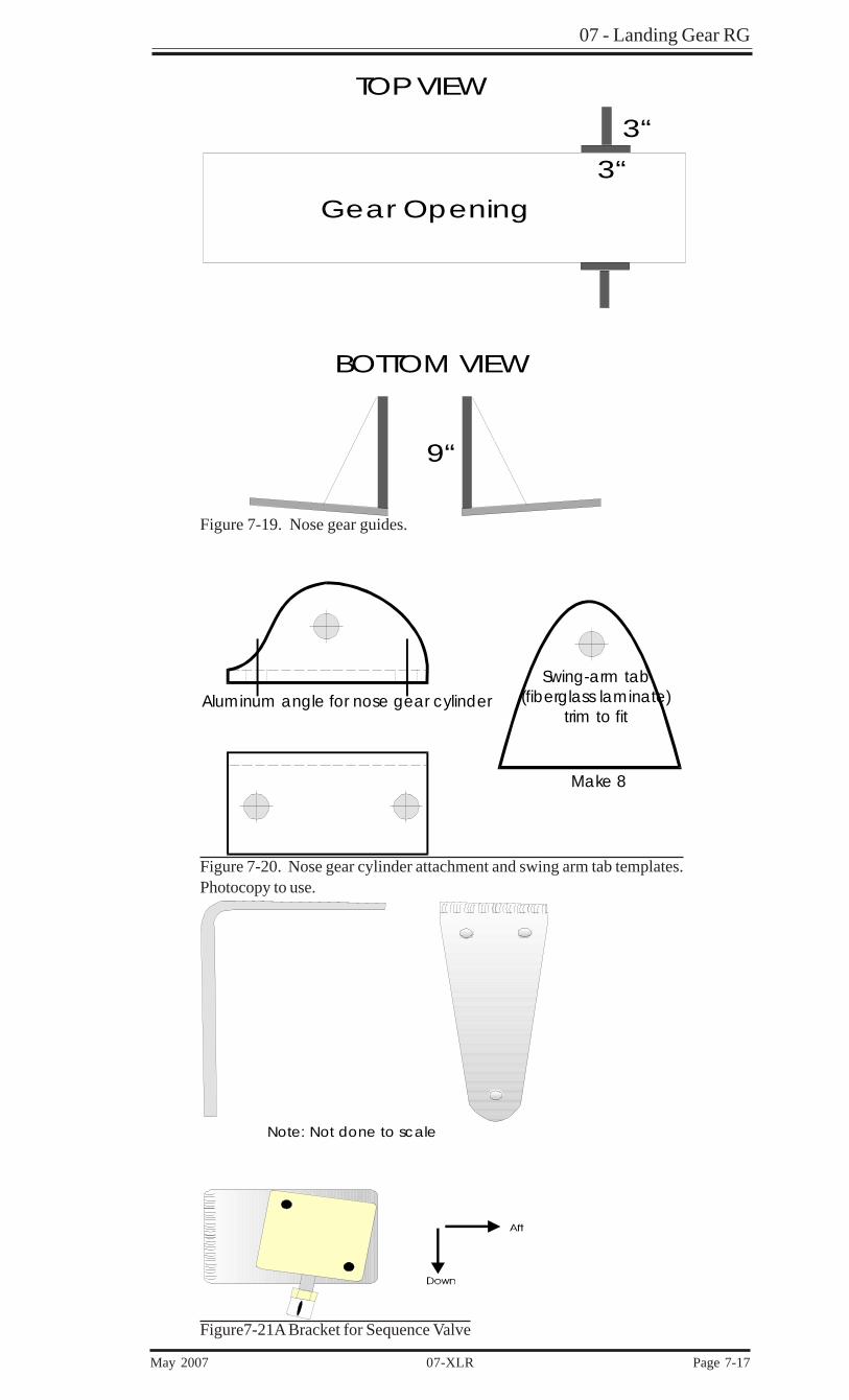
Figure 7-19. Nose gear guides.
Swing-arm tab(fiberglass laminate)
trim to fitAluminum angle for nose gear cylinder
Make 8
Figure 7-20. Nose gear cylinder attachment and swing arm tab templates.Photocopy to use.
Note: Not done to scale
Figure7-21A Bracket for Sequence Valve
07- Landing Gear RG
Page 7-18 07-XLR May 2007
○
○
○
○
○
○
○
○
○
○
○
○
○
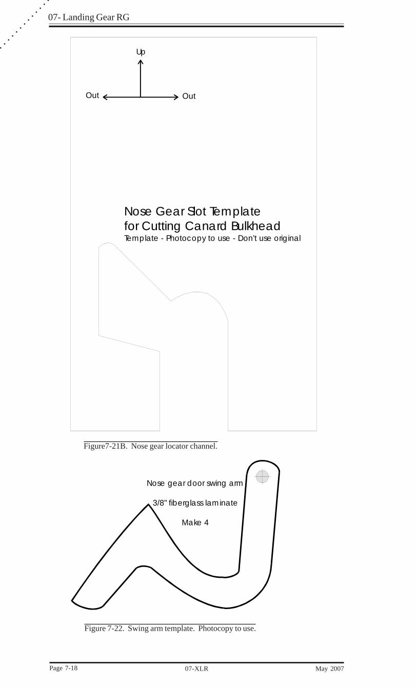
Nose gear door swing arm
3/8" fiberglass laminate
Make 4
Up
OutOut
Nose Gear Slot Templatefor Cutting Canard BulkheadTemplate - Photocopy to use - Don’t use original
Figure 7-22. Swing arm template. Photocopy to use.
Figure7-21B. Nose gear locator channel.
07 - Landing Gear RG
May 2007 07-XLR Page 7-19
7.3 - Main Gear Preparation
7.3.1 - Gear Leg Preparation
The main gear comes to you with a 5/8" hole where the bushing will go. This holeshould have been reamed for a good fit here at the factory so you should not have todo any fitting.
7.3.2 - Gear Leg Torsional Reinforcement
___ Completely sand the legs with 36 - 40 grit sandpaper in preparation for the torsionallay-ups.
___ Jig the gear legs, leading edge down with the tips on the table, and lightly Bondothem so they can not move around. Try to avoid getting any Bondo on the othersurfaces of the gear leg.
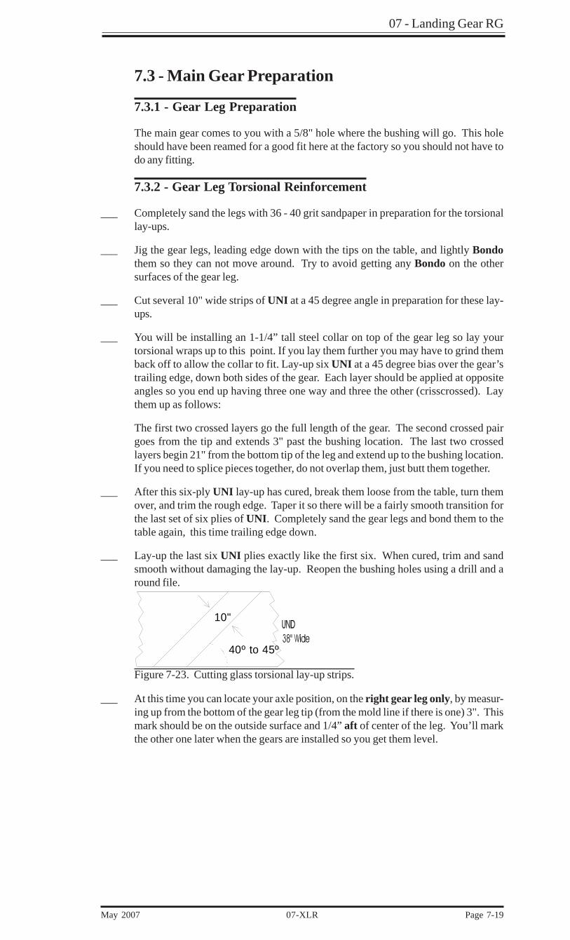
___ Cut several 10" wide strips of UNI at a 45 degree angle in preparation for these lay-ups.
___ You will be installing an 1-1/4” tall steel collar on top of the gear leg so lay yourtorsional wraps up to this point. If you lay them further you may have to grind themback off to allow the collar to fit. Lay-up six UNI at a 45 degree bias over the gear’strailing edge, down both sides of the gear. Each layer should be applied at oppositeangles so you end up having three one way and three the other (crisscrossed). Laythem up as follows:
The first two crossed layers go the full length of the gear. The second crossed pairgoes from the tip and extends 3" past the bushing location. The last two crossedlayers begin 21" from the bottom tip of the leg and extend up to the bushing location.If you need to splice pieces together, do not overlap them, just butt them together.
___ After this six-ply UNI lay-up has cured, break them loose from the table, turn themover, and trim the rough edge. Taper it so there will be a fairly smooth transition forthe last set of six plies of UNI. Completely sand the gear legs and bond them to thetable again, this time trailing edge down.
___ Lay-up the last six UNI plies exactly like the first six. When cured, trim and sandsmooth without damaging the lay-up. Reopen the bushing holes using a drill and around file.
10"
40º to 45º
Figure 7-23. Cutting glass torsional lay-up strips.
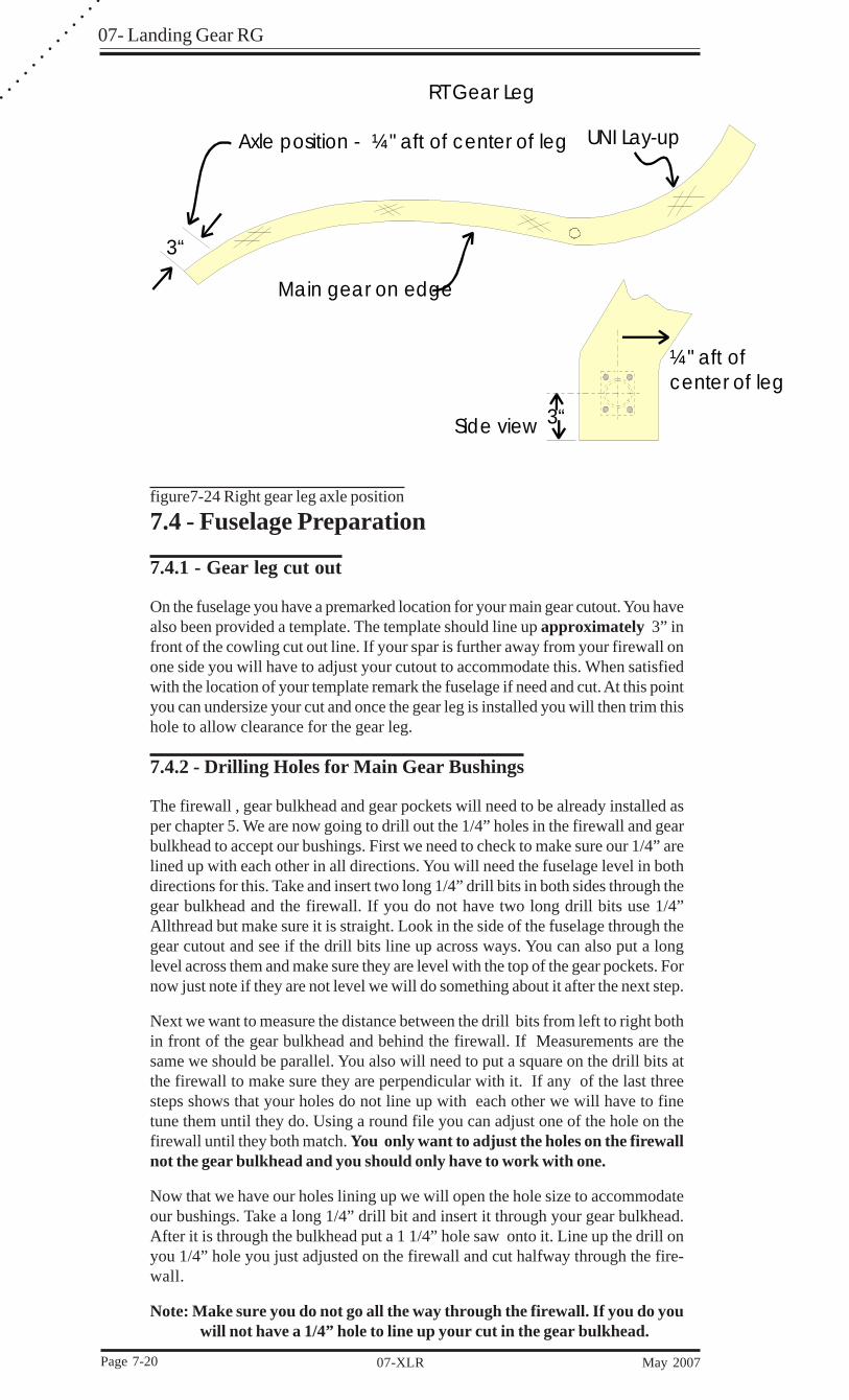
___ At this time you can locate your axle position, on the right gear leg only, by measur-ing up from the bottom of the gear leg tip (from the mold line if there is one) 3". Thismark should be on the outside surface and 1/4” aft of center of the leg. You’ll markthe other one later when the gears are installed so you get them level.
07- Landing Gear RG
Page 7-20 07-XLR May 2007
○
○
○
○
○
○
○
○
○
○
○
○
○
Main gear on edge
UNI Lay-up
RT Gear Leg
Axle position - ¼" aft of center of leg
3“
3“
¼" aft ofcenter of leg
Side view
figure7-24 Right gear leg axle position
7.4 - Fuselage Preparation
7.4.1 - Gear leg cut out
On the fuselage you have a premarked location for your main gear cutout. You havealso been provided a template. The template should line up approximately 3” infront of the cowling cut out line. If your spar is further away from your firewall onone side you will have to adjust your cutout to accommodate this. When satisfiedwith the location of your template remark the fuselage if need and cut. At this pointyou can undersize your cut and once the gear leg is installed you will then trim thishole to allow clearance for the gear leg.
7.4.2 - Drilling Holes for Main Gear Bushings
The firewall , gear bulkhead and gear pockets will need to be already installed asper chapter 5. We are now going to drill out the 1/4” holes in the firewall and gearbulkhead to accept our bushings. First we need to check to make sure our 1/4” arelined up with each other in all directions. You will need the fuselage level in bothdirections for this. Take and insert two long 1/4” drill bits in both sides through thegear bulkhead and the firewall. If you do not have two long drill bits use 1/4”Allthread but make sure it is straight. Look in the side of the fuselage through thegear cutout and see if the drill bits line up across ways. You can also put a longlevel across them and make sure they are level with the top of the gear pockets. Fornow just note if they are not level we will do something about it after the next step.
Next we want to measure the distance between the drill bits from left to right bothin front of the gear bulkhead and behind the firewall. If Measurements are thesame we should be parallel. You also will need to put a square on the drill bits atthe firewall to make sure they are perpendicular with it. If any of the last threesteps shows that your holes do not line up with each other we will have to finetune them until they do. Using a round file you can adjust one of the hole on thefirewall until they both match. You only want to adjust the holes on the firewallnot the gear bulkhead and you should only have to work with one.
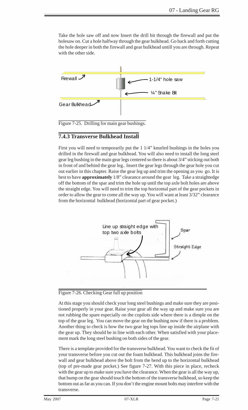
Now that we have our holes lining up we will open the hole size to accommodateour bushings. Take a long 1/4” drill bit and insert it through your gear bulkhead.After it is through the bulkhead put a 1 1/4” hole saw onto it. Line up the drill onyou 1/4” hole you just adjusted on the firewall and cut halfway through the fire-wall.
Note: Make sure you do not go all the way through the firewall. If you do youwill not have a 1/4” hole to line up your cut in the gear bulkhead.
07 - Landing Gear RG
May 2007 07-XLR Page 7-21
Take the hole saw off and now Insert the drill bit through the firewall and put theholesaw on. Cut a hole halfway through the gear bulkhead. Go back and forth cuttingthe hole deeper in both the firewall and gear bulkhead untill you are through. Repeatwith the other side.
Firewall
Gear Bulkhead
1-1/4“ hole saw
¼" Snake Bit
Figure 7-25. Drilling for main gear bushings.
7.4.3 Transverse Bulkhead Install
First you will need to temporarily put the 1 1/4” knurled bushings in the holes youdrilled in the firewall and gear bulkhead. You will also need to install the long steelgear leg bushing in the main gear legs centered so there is about 3/4” sticking out bothin front of and behind the gear leg.. Insert the gear legs through the gear hole you cutout earlier in this chapter. Raise the gear leg up and trim the opening as you go. It isbest to have approximately 1/8” clearance around the gear leg. Take a straightedgeoff the bottom of the spar and trim the hole up until the top axle bolt holes are abovethe straight edge. You will need to trim the top horizontal part of the gear pockets inorder to allow the gear to come all the way up. You will want at least 3/32” clearancefrom the horizontal bulkhead (horizontal part of gear pocket.)
Figure 7-26. Checking Gear full up position
At this stage you should check your long steel bushings and make sure they are posi-tioned properly in your gear. Raise your gear all the way up and make sure you arenot rubbing the spare especially on the copilots side where there is a dimple on thetop of the gear leg. You can move the gear on the bushing now if there is a problem.Another thing to check is how the two gear leg tops line up inside the airplane withthe gear up. They should be in line with each other. When satisfied with your place-ment mark the long steel bushing on both sides of the gear.
There is a template provided for the transverse bulkhead. You want to check the fit ofyour transverse before you cut out the foam bulkhead. This bulkhead joins the fire-wall and gear bulkhead above the bolt from the bend up to the horizontal bulkhead(top of pre-made gear pocket.) See figure 7-27. With this piece in place, recheckwith the gear up to make sure you have the clearance. When the gear is all the way up,that bump on the gear should touch the bottom of the transverse bulkhead, so keep thebottom out as far as you can. If you don’t the engine mount bolts may interfere with thetransverse.
Line up straight edge withtop two axle bolts

07- Landing Gear RG
Page 7-22 07-XLR May 2007
○
○
○
○
○
○
○
○
○
○
○
○
○
When you are satisfied with your fit and you have marked this position, use Bondo toattach the bulkhead on the top ledge first. This allows you a final check of with thegear up to get the bottom of the bulkhead where you want it. Bondo the bottom of thetemplate.
Gear bulkhead
Gear
Bend
Foam hits against gear bump
¼" foam transverse bulkhead
Spar
¼" foamhorizontalbulkhead
Figure 7-27. Transverse bulkhead position
Be careful when you remove the gear not to upset the bulkhead. Get your lay-uptemplates and lay them in position to check for fit and modify if necessary. Whensatisfied, cut four plies of TRIAX, two for each outside off one template, and fourplies, two for each inside off the other template.
___ Pre-wet the TRIAX on plastic. Let these layups sit 1 to 2 hours until they are tacky.This is so they will stick to a vertical service without draining epoxy. Micro-Slurrythe foam, radius corners, and apply across the transverse bulkhead, lapping onto thefirewall, gear bulkhead, across the bolt holes in both directions, up to the horizontalbulkhead on the outside, and up onto that bulkhead on the inside. Once in place,remove the plastic and squeegee. Make sure the lay-up stays in the corners. Youmay use a hair dryer to heat up your layup to ensure a good bond.
07 - Landing Gear RG
May 2007 07-XLR Page 7-23
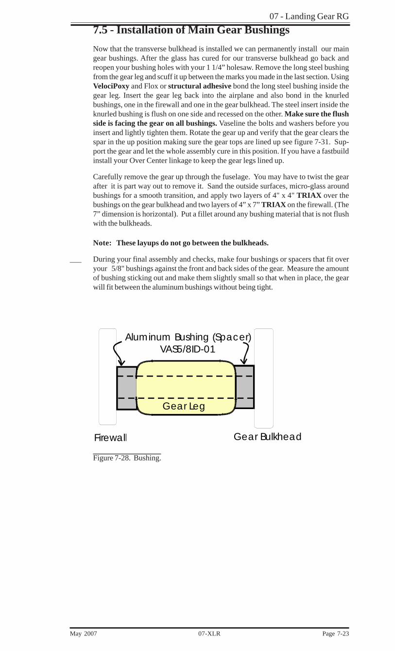
7.5 - Installation of Main Gear BushingsNow that the transverse bulkhead is installed we can permanently install our maingear bushings. After the glass has cured for our transverse bulkhead go back andreopen your bushing holes with your 1 1/4” holesaw. Remove the long steel bushingfrom the gear leg and scuff it up between the marks you made in the last section. UsingVelociPoxy and Flox or structural adhesive bond the long steel bushing inside thegear leg. Insert the gear leg back into the airplane and also bond in the knurledbushings, one in the firewall and one in the gear bulkhead. The steel insert inside theknurled bushing is flush on one side and recessed on the other. Make sure the flushside is facing the gear on all bushings. Vaseline the bolts and washers before youinsert and lightly tighten them. Rotate the gear up and verify that the gear clears thespar in the up position making sure the gear tops are lined up see figure 7-31. Sup-port the gear and let the whole assembly cure in this position. If you have a fastbuildinstall your Over Center linkage to keep the gear legs lined up.
Carefully remove the gear up through the fuselage. You may have to twist the gearafter it is part way out to remove it. Sand the outside surfaces, micro-glass aroundbushings for a smooth transition, and apply two layers of 4" x 4" TRIAX over thebushings on the gear bulkhead and two layers of 4” x 7” TRIAX on the firewall. (The7” dimension is horizontal). Put a fillet around any bushing material that is not flushwith the bulkheads.
Note: These layups do not go between the bulkheads.
___ During your final assembly and checks, make four bushings or spacers that fit overyour 5/8" bushings against the front and back sides of the gear. Measure the amountof bushing sticking out and make them slightly small so that when in place, the gearwill fit between the aluminum bushings without being tight.
Gear Leg
Aluminum Bushing (Spacer) VAS5/8ID-01
Firewall Gear Bulkhead
Figure 7-28. Bushing.

07- Landing Gear RG
Page 7-24 07-XLR May 2007
○
○
○
○
○
○
○
○
○
○
○
○
○
___
Washer
Steel Bushing
AluminumBushings
SteelLocknut
4“ x 4” TRIAX2 Plies
4“ x 7” TRIAX2 Piles7“ Dimension Horizontal
*Make sure your bushingsare flush or slightly protruding towards the gear leg
Firewall
GearBulkhead
Figure 7-30. Installing Main Gear Bushings VMGBBA-01
Gear Leg Gear Leg
Gear bulkhead
Lined up
Looking down
Spar
Figure 7-31. Main gear strut alignment.
07 - Landing Gear RG
May 2007 07-XLR Page 7-25
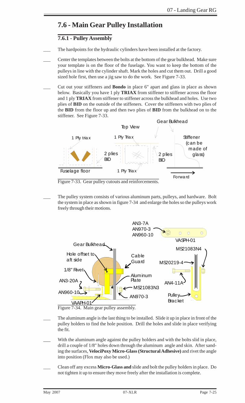
7.6 - Main Gear Pulley Installation
7.6.1 - Pulley Assembly
___ The hardpoints for the hydraulic cylinders have been installed at the factory.
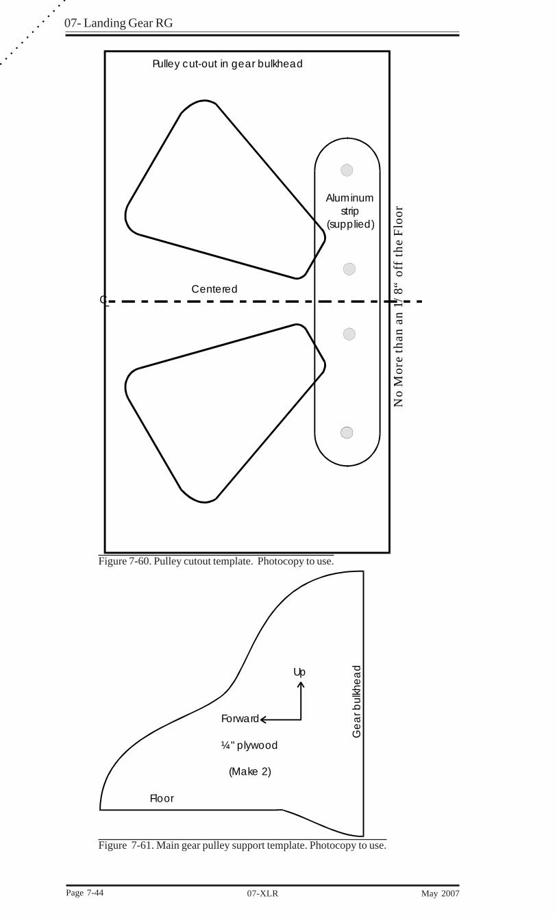
___ Center the templates between the bolts at the bottom of the gear bulkhead. Make sureyour template is on the floor of the fuselage. You want to keep the bottom of thepulleys in line with the cylinder shaft. Mark the holes and cut them out. Drill a goodsized hole first, then use a jig saw to do the work. See Figure 7-33.
___ Cut out your stiffeners and Bondo in place 6" apart and glass in place as shownbelow. Basically you have 1 ply TRIAX from stiffener to stiffener across the floorand 1 ply TRIAX from stiffener to stiffener across the bulkhead and holes. Use twoplies of BID on the outside of the stiffeners. Cover the stiffeners with two plies ofthe BID from the floor up and then two plies of BID from the bulkhead on to thestiffener. See Figure 7-33.
Forward
Top ViewGear Bulkhead
1 Ply triax
1 Ply Triax
1 Ply Triax Stiffener (can be made of glass)2 plies
BID2 pliesBID
Fuselage floor
Figure 7-33. Gear pulley cutouts and reinforcements.
___ The pulley system consists of various aluminum parts, pulleys, and hardware. Boltthe system in place as shown in figure 7-34 and enlarge the holes so the pulleys workfreely through their motions.
Gear Bulkhead
AN3-20AAluminumPlate
MS21083N3
AN970-3AN960-10
1/8" Rivet
AN4-11A
MS21083N4
PulleyBracket
MS20219-4
AN3-7AAN970-3AN960-10
VASPH-01
VAAPH-01
Hole offset toaft side
Cable Guard
Figure 7-34. Main gear pulley assembly.
___ The aluminum angle is the last thing to be installed. Slide it up in place in front of thepulley holders to find the hole position. Drill the holes and slide in place verifyingthe fit.
___ With the aluminum angle against the pulley holders and with the bolts slid in place,drill a couple of 1/8" holes down through the aluminum angle and skin. After sand-ing the surfaces, VelociPoxy Micro-Glass (Structural Adhesive) and rivet the angleinto position (Flox may also be used.)
___ Clean off any excess Micro-Glass and slide and bolt the pulley holders in place. Donot tighten it up to ensure they move freely after the installation is complete.

07- Landing Gear RG
Page 7-26 07-XLR May 2007
○
○
○
○
○
○
○
○
○
○
○
○
○
SteelCollarVSCMG-01
Out
Up
Gear Leg
Mark
Duct Tape
Rounded top toclear gusset inlinkage
Centered Hole
Figure 7-35. Gear leg socket layup.
___ Make a jig by taking a nice piece of straight lumber, 2" x 2" x 28", and drill two holes26" apart, parallel to each other and level. It’s easiest to do this on a drill press. The26" dimension does not match the overcenter linkage, it is for ease of drilling.
Note: Check assembly for unobstructed movement and clearance aroundthe RG cables. You may need to relieve the aluminum parts with a file toassure there is no binding. If the pulley holders are installed too high aside load will be placed on the main gear cylinder and will cause it to wearprematurely.
7.6.2 - Main Gear Overcenter Linkage and Sockets
___ While your gears are in the fuselage, mark them where they touch the bottom of thehorizontal bulkhead (Top of gear pocket) and then remove them.
___ Verify that the distance from the center of the 5/8” pivot bushing to the top of bothgear legs is 17”.
___ Clean the ends and install the steel collars flush with the top of the legs with VelociPoxyMicro-Glass( Structural Adhesive).
___ Duct tape the whole area down past the mark you made. Pre-wet three plies ofTRIAX, axis the long way, wide enough to reach at least 1/3 the way around, andlong enough to go past your mark at the bottom. Lay the TRIAX on your gear legs andlet cure. After cured, remove the sockets, and remove the duct tape. This piecebecomes the Gear Socket into which the gear leg will fit when extended.
___ Find the center of those collars on the forward side (facing the nose), and drill 3/8"holes just through the steel collar on both gears.
2" x 2" x 28"
26"Figure 6-36. Main gear leg drill jig.
___ Slide two bolts through the holes and check their alignment. Put your drilling jig upin place against those collars. Make sure the gear legs are an even distance out fromthe firewall. If one gear is further back than the other, you will have to position yourjig out away a little so your holes will go through straight and parallel to the center-line of the fuselage. Have someone help you.
___ Level the board as you drill the hole a little at a time. Drill half way through, slide abolt in the hole, drill half way through the other side. Repeat until all the waythrough.
07 - Landing Gear RG
May 2007 07-XLR Page 7-27
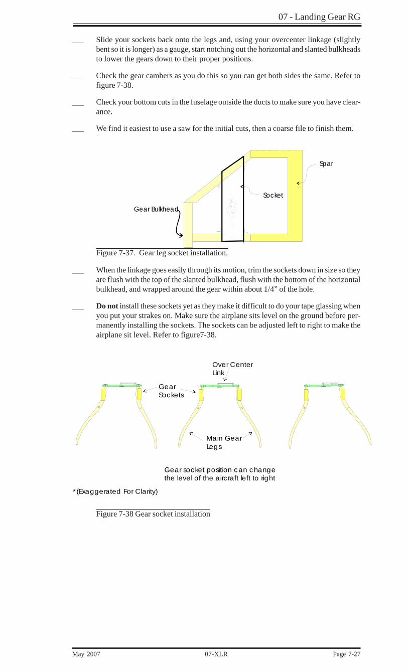
___ Slide your sockets back onto the legs and, using your overcenter linkage (slightlybent so it is longer) as a gauge, start notching out the horizontal and slanted bulkheadsto lower the gears down to their proper positions.
___ Check the gear cambers as you do this so you can get both sides the same. Refer tofigure 7-38.
___ Check your bottom cuts in the fuselage outside the ducts to make sure you have clear-ance.
___ We find it easiest to use a saw for the initial cuts, then a coarse file to finish them.
Spar
Socket
Gear Bulkhead
Figure 7-37. Gear leg socket installation.
___ When the linkage goes easily through its motion, trim the sockets down in size so theyare flush with the top of the slanted bulkhead, flush with the bottom of the horizontalbulkhead, and wrapped around the gear within about 1/4” of the hole.
___ Do not install these sockets yet as they make it difficult to do your tape glassing whenyou put your strakes on. Make sure the airplane sits level on the ground before per-manently installing the sockets. The sockets can be adjusted left to right to make theairplane sit level. Refer to figure7-38.
Main GearLegs
Over CenterLink
GearSockets
*(Exaggerated For Clarity)
Gear socket position can change the level of the aircraft left to right
Figure 7-38 Gear socket installation
07- Landing Gear RG
Page 7-28 07-XLR May 2007
○
○
○
○
○
○
○
○
○
○
○
○
○
MM
3M-1
2 ro
d e
ndM
W3
rod
end
s
Pulle
y b
rac
ket
Ca
ble
Sid
e s
tiffe
ner
left
out
for c
larit
y
MS2
0219
-4 p
ulle
yG
ea
rb
ulkh
ea
d
Side
View
From
Co-
pilo
t Sid
e
Top
Vie
w
Alu
min
um a
ngle
VABM
GC
-01
(2) M
S210
44N
4 nu
ts(2
) AN
960-
416
wa
she
rs
(4) M
S210
44N
4 nu
ts(4
) AN
960-
416
wa
she
rs
(6) M
S246
94S-
106
scre
ws
co
unte
rsun
k th
roug
hha
rdp
oin
t bur
ied
insid
e fl
oo
r
VMC
MA-
01
Ca
ble
Gua
rd
VASM
GC
-01
UP-T
rave
l Sp
ac
er
Sid
e V
iew
Loo
king
Fo
rwa
rd
MM
3M12
- R
od
-end
MW
3 -
Rod
-end
MW
3 -
Rod
-end
MS2
0219
-4 P
ulle
y
AN
316-
4 Ja
m-n
ut
AN
970-
4 W
ash
er
MM
3M12
- M
ale
Ro
d-e
nd(N
o w
ash
ers
be
twe
en
pla
tes
on
ce
nte
r ro
d-e
nd)
(3) A
N3-
7A B
olt
(3) 3
/16”
Wa
she
r (Th
in):
AN96
0-10
(1) C
ab
le J
oin
er P
late
: VAC
JP-0
1
(2) 3
/16”
Wa
she
r (Th
ick)
: AN
960-
10L
(2) M
W-3
Fe
ma
le R
od
-end
(2) 3
/16”
Wa
she
r (Th
ick)
: AN
960-
10L
(1) C
ab
le J
oin
er P
late
: VAC
JP-0
1
(3) 3
/16”
Wa
she
r (Th
in):
AN96
0-10
(3) L
oc
knut
: MS2
1042
-3
Fore
| A
ft
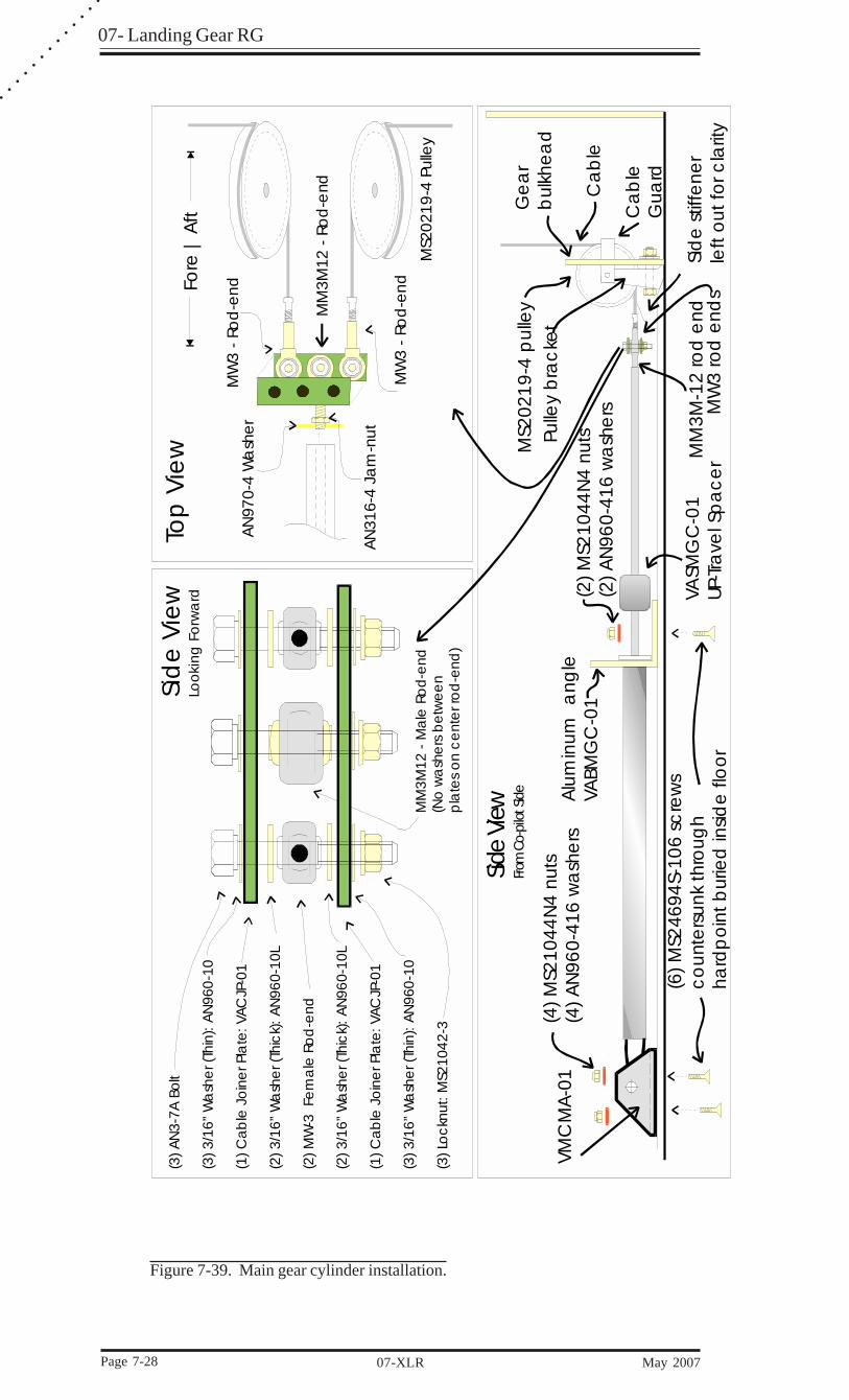
Figure 7-39. Main gear cylinder installation.

07 - Landing Gear RG
May 2007 07-XLR Page 7-29
7.6.3 - Hydraulic Cylinder
___ Locate the three wood hardpoints in the floor as described in Figure 7-40.
___ Mount the front cylinder mounting brackets with a total of (4) four MS24694S-109screws and bolt in place using (2) two MS24694S-109 screws as shown in Figures7-39 and Figure 7-40.
___ The cylinders do not have to be exactly in the middle of the hardpoints. If the cylinderis closer than 29-1/2” from the bulkhead check to make sure that the end of thecylinder shaft is far enough away from the pulleys to allow the rod ends to fit.
29-1/2“ toCL of pad
57“ to CL of pad56.5“ to pivot CL
Bolt angle in place aftercylinder is mounted
Fuselage CLFuselage CL
3.5" x 3.5" x ¼" plywood
2 plies TRIAX5.5" x 7" over wood
Top view
Gearbulkhead
57"&29-1/2“
7-40. Main Gear Cylinder Mounting
7.6.4 - Cables
___ With the gear down and centered, and the overcenter link straight you can install thecables. You may want to wait until your gear sockets have been permanently mountedbefore doing this but as long as the legs are in the right position, you can proceed.
AN111-3Cable Thimble
AN3-5A
AN364-1032A
Bushing
3/32" Cable
Overcenterlinkage
Figure 7-41. Main gear cable attachment.
___ Adjust all of your rod ends (3) to about the middle of their travel. Assemble them inthe method prescribed in the blowup views in fig. 7-39. Extend the clean end throughthe pulleys and up to the overcenter linkage tabs. Route the cables around the AN111thimbles with the bolt in place to simulate the proper length and mark the cables.Make sure the rod ends are all lined up since they will angle when pulled one at atime.
With the cylinder fully extended and the gear down and locked the cables should be alittle snug. Too tight and the OC link can be prematurely actuated. If the cables arereally loose a cable can come off a pulley.

07- Landing Gear RG
Page 7-30 07-XLR May 2007
○
○
○
○
○
○
○
○
○
○
○
○
○
7.7 - Installing the Main Gear
7.7.1 - Gear Legs
___ Install both gears in the fuselage, with the overcenter linkage in place and centered,and the fuselage leveled laterally and the cambers the same on both sides.
Main Gear Leg
Overcenter linkagetoward front
Pilot’s SideBolt: AN6-26A
Co-Pilot’s SideBolt: AN6-27A
Figure 7-42. Main gear legs.
___ From the previous axle position mark that you put on one leg, pull a string from thatmark to the other leg. Use duct tape to hold the string on. Level that string with a 4foot carpenter’s level, and mark the other gear.
Remember that the axle position on the right gear leg was 1/4" aft of center. Locatethis axle 1/4" aft as well.
___ Move the gear up and down with the linkage installed. Ensure that there is clearancebetween the top of the gear leg and the linkage and grind the top of the leg and steelcollar as necessary.
7.7.2 - Brake Lines
___ Cut two pieces of Nylaflow, one for each side, that will reach from the calipers upabout 1 foot inside the fuselage. You will trim and hook the lines up later. Somebuilders have elected to mount a slightly larger Nylaflow conduit or drinking straws,which will contain the smaller Nylaflow brake line so that the line may be replacedin the future.
ForwardIn
Nylaflow1 ply BID
Micro
Gear Leg(Inside)
1 ply BiID
Nylaflow¼" back fromleading edge
Straw
Figure7-43. Brake lines.
___ First 5 Minute Epoxy the line in place along the bottom leading edge of the gear leg.Once installed, Micro-Glass the sides of the Nylaflow and glass with one ply ofBID from 10" from the end of the leg to within 1/2” of the fuselage.
7.7.3 - Main Gear Doors
Note: Before installing the main gear doors, the fuel strakes must be com-pletely installed. Go to Chapter 9 for instructions on the fuel system.
The last step of fuel strake installation is glassing the spar to strake junction. To dothat, you will need to invert the fuselage.
07 - Landing Gear RG
May 2007 07-XLR Page 7-31
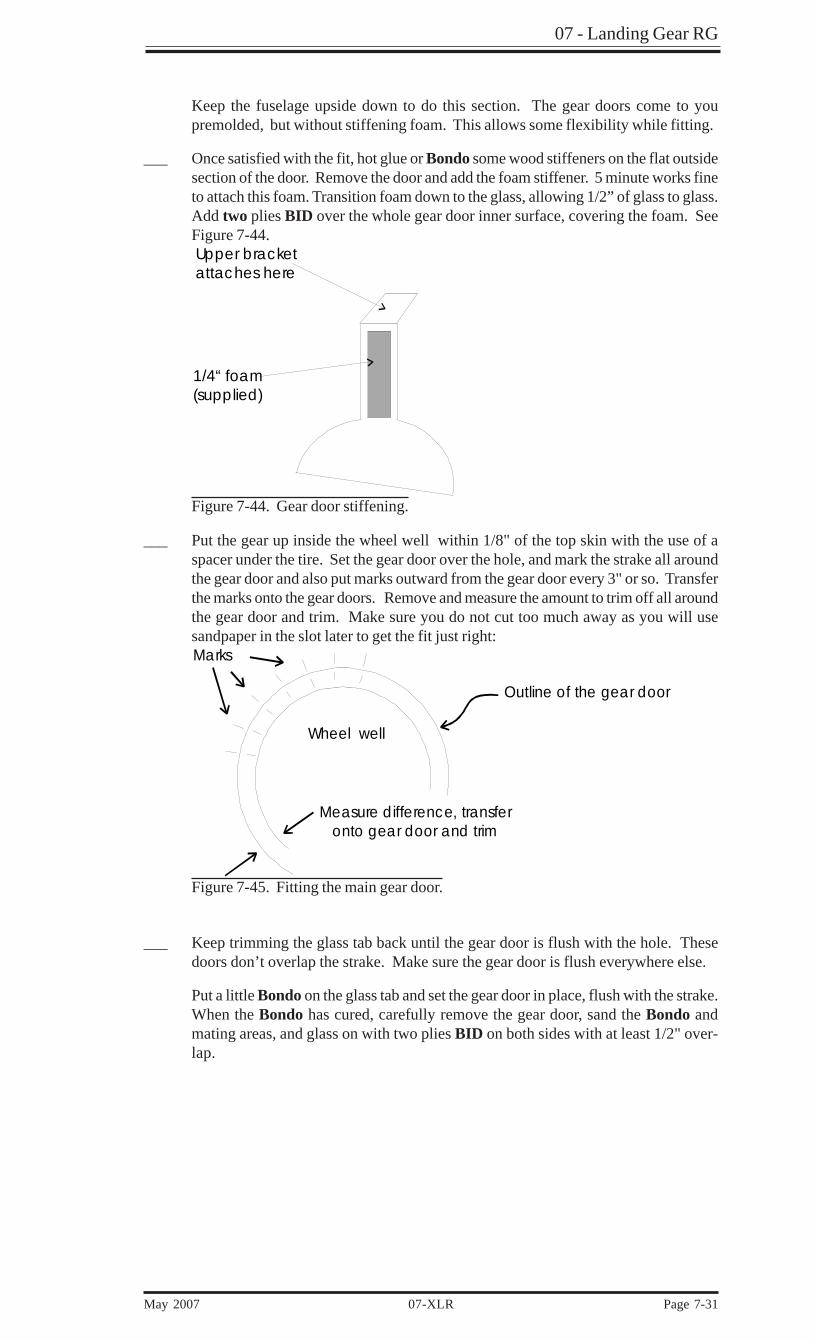
Keep the fuselage upside down to do this section. The gear doors come to youpremolded, but without stiffening foam. This allows some flexibility while fitting.
___ Once satisfied with the fit, hot glue or Bondo some wood stiffeners on the flat outsidesection of the door. Remove the door and add the foam stiffener. 5 minute works fineto attach this foam. Transition foam down to the glass, allowing 1/2” of glass to glass.Add two plies BID over the whole gear door inner surface, covering the foam. SeeFigure 7-44.Upper bracketattaches here
1/4“ foam(supplied)
Figure 7-44. Gear door stiffening.
___ Put the gear up inside the wheel well within 1/8" of the top skin with the use of aspacer under the tire. Set the gear door over the hole, and mark the strake all aroundthe gear door and also put marks outward from the gear door every 3" or so. Transferthe marks onto the gear doors. Remove and measure the amount to trim off all aroundthe gear door and trim. Make sure you do not cut too much away as you will usesandpaper in the slot later to get the fit just right:Marks
Outline of the gear door
Wheel well
Measure difference, transfer onto gear door and trim
Figure 7-45. Fitting the main gear door.
___ Keep trimming the glass tab back until the gear door is flush with the hole. Thesedoors don’t overlap the strake. Make sure the gear door is flush everywhere else.
Put a little Bondo on the glass tab and set the gear door in place, flush with the strake.When the Bondo has cured, carefully remove the gear door, sand the Bondo andmating areas, and glass on with two plies BID on both sides with at least 1/2" over-lap.
07- Landing Gear RG
Page 7-32 07-XLR May 2007
○
○
○
○
○
○
○
○
○
○
○
○
○
Aluminum angle
Fiberglass tab(from instrument panel)
10-32 nutplate,10-32 screw throughgear door
Gear
Gear DoorRivets
2 bid each side
Fuselage
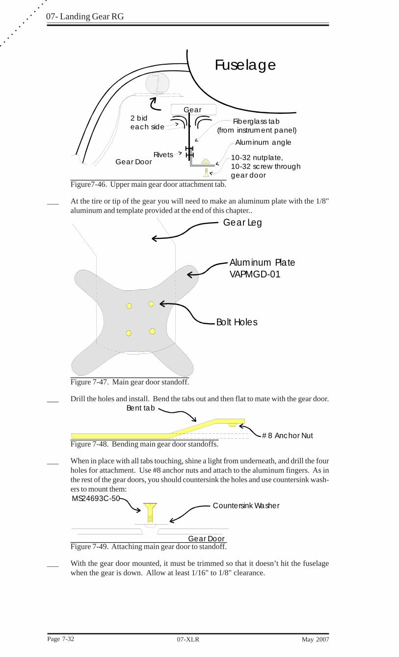
Figure7-46. Upper main gear door attachment tab.
___ At the tire or tip of the gear you will need to make an aluminum plate with the 1/8"aluminum and template provided at the end of this chapter..
Gear Leg
Aluminum PlateVAPMGD-01
Bolt Holes
Figure 7-47. Main gear door standoff.
___ Drill the holes and install. Bend the tabs out and then flat to mate with the gear door.Bent tab
#8 Anchor NutFigure 7-48. Bending main gear door standoffs.
___ When in place with all tabs touching, shine a light from underneath, and drill the fourholes for attachment. Use #8 anchor nuts and attach to the aluminum fingers. As inthe rest of the gear doors, you should countersink the holes and use countersink wash-ers to mount them:MS24693C-50
Countersink Washer
Gear DoorFigure 7-49. Attaching main gear door to standoff.
___ With the gear door mounted, it must be trimmed so that it doesn’t hit the fuselagewhen the gear is down. Allow at least 1/16" to 1/8" clearance.

07 - Landing Gear RG
May 2007 07-XLR Page 7-33
Fuselage SideClearance
Gear Door
Gear Leg
Figure 6-50. Trimming main gear door.
______ With the gear up, use some sandpaper with the sandy side facing the door, to sand a 1/
8" gap all around the door for clearance.
___ Once the fuselage is turned back over, you can go ahead and install those sockets youfit a long time ago. Make sure you have already checked your tank for leaksbecause after the sockets are installed it is hard to get at the back portion of thetank. Slide the sockets onto the gear legs and install the overcenter linkage. Putsome Micro-Glass into the slots where the sockets will go. Lower the gear into thedown and locked position.
___ After cured, sand and round rough areas, add a Micro-Glass radius where it contactthe gear bulkheads, and glass the sockets into place with two BID at each junction.Make sure you do not get any glass on the inside surface of the socket where it comesin contact with the gear.
* * *
07- Landing Gear RG
Page 7-34 07-XLR May 2007
○
○
○
○
○
○
○
○
○
○
○
○
○
7.8 - Hydraulic System
7.8.1 - Hydraulic Power Pack and Nose Gear Door Cylinder
The power pack is a self contained unit comprising motor, gear driven pump, andreservoir. The unit can actually be in any one of several locations. The recom-mended location is on the forward side of the canard bulkhead on the copilot side.
___ Position the power pack for minimum interference and accessibility. Mark holelocation and drill through the bulkhead and mount with appropriate bolts.
CL
2.1875“
#10-32 screwSpring
GuideVAASG-01
Spacer (if needed)
Aluminumangle AN3-10A
#10 sheet metal screws
Go no higher thantop of bulkhead
AN970-6 Large Area Washers
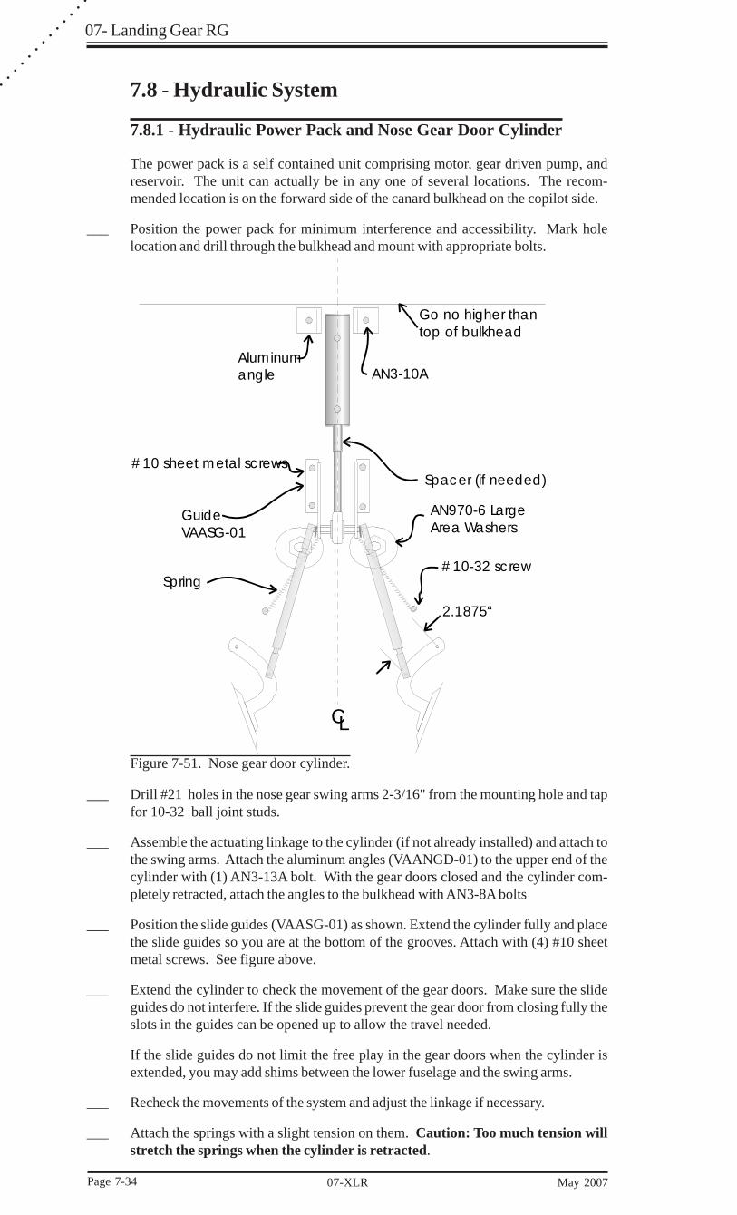
Figure 7-51. Nose gear door cylinder.
___ Drill #21 holes in the nose gear swing arms 2-3/16" from the mounting hole and tapfor 10-32 ball joint studs.
___ Assemble the actuating linkage to the cylinder (if not already installed) and attach tothe swing arms. Attach the aluminum angles (VAANGD-01) to the upper end of thecylinder with (1) AN3-13A bolt. With the gear doors closed and the cylinder com-pletely retracted, attach the angles to the bulkhead with AN3-8A bolts
___ Position the slide guides (VAASG-01) as shown. Extend the cylinder fully and placethe slide guides so you are at the bottom of the grooves. Attach with (4) #10 sheetmetal screws. See figure above.
___ Extend the cylinder to check the movement of the gear doors. Make sure the slideguides do not interfere. If the slide guides prevent the gear door from closing fully theslots in the guides can be opened up to allow the travel needed.
If the slide guides do not limit the free play in the gear doors when the cylinder isextended, you may add shims between the lower fuselage and the swing arms.
___ Recheck the movements of the system and adjust the linkage if necessary.
___ Attach the springs with a slight tension on them. Caution: Too much tension willstretch the springs when the cylinder is retracted.
07 - Landing Gear RG
May 2007 07-XLR Page 7-35
___ Once all is adjusted properly, hand check the up and down positions of the nose geardoors to insure proper action. Loctite all in place except the upper ball joint topushrod joint. This can later be trimmed if needed for adjustment. Note: The balljoints are made to snap out of the mating part, making disassembly and reas-sembly easier.
Proceed to complete assembly of all cylinders and sequence valve if you have not yetdone so.
7.8.2 - Plumbing
The plumbing of the hydraulic system includes proper AN fittings, high and lowpressure switches, aluminum tubing, flex hose, and associated hardware. Aluminumtubing must be bent using spring bending tools or better.
It is also important to buy or borrow a proper 1/4” tube flaring tool. Remember, weare using AN fittings and proper flare is important. That means a flare of 37 degrees.A standard automotive flare (hardware store variety) is different and using itwith these fittings will cause a system failure!
___ Mount the AN804-4D firewall unions through the bulkhead in the positions as shownin Figure7-52.
___ Mount the high and low pressure switches to the pump using AN834-4D T’s.
___ Route aluminum tubing and connect per Figure 7-52.
___ Route aluminum tubing to sequence valve and dump valve per Figure 7-54.
___ The dump valve mounts on the copilot side of the keel in the premarked position justin front of the instrument panel. It can be located elsewhere.
___ Assemble the hose fittings to the hydraulic hose and attach to the cylinder as shown inFigure 7-52.
To assemble the hose ends first take a 3” long piece of 2”x2” wood and drill a 3/8”hole down through the center of it. Cut your block in two running right down thecenter of the hole you just drill lengthwise. This will be used to clamp the hose. Inserta 3/16” drill bit into the end of your hose. Insert the hose in your block with about 1-1/4” sticking above the block and clamp it in a vise. Use oil as lubrication whileassembling. Take the outer sleeve portion of your end fitting and screw it onto the endof your hose counter- clockwise. You will be able to see the end of the hose bottomout inside the fitting. Remove the block from the vise and using pliers remove the 3/16” drill bit. Clamp hose end in the vise. Insert an 1/8” drill bit into the insert portionof your end fitting. This will help guide the insert as it is started into the hose. Usinga 9/16” wrench, screw the insert in clockwise until it bottoms out. Try not to stopwhile screwing the insert in. As you screw in the insert the friction heats up the hoseand makes it easier to screw it in. If you stop and start while screwing the fitting inyou will have a harder time. Do not try and make it too tight. You will wind upsnapping the head off of the insert. Remove the 1/8” drill bit.
7.8.3 - Pressure switch adjustment.
Both pressure switches may need to be adjusted. To do this will require a 0-2000 psigauge. Some people have install permanent gauges in their airplanes but it really isnot necessary.
___ Plumb the gauge into the retract side first, and once you have cycled the gear a fewtimes to remove air from the system, remove the rubber cap from the pressure switch.This will expose one screw adjuster.
___ Increase pressure by turning clockwise (tightening) equally so the gear will completeits full cycle without the pump cycling and pressure will show about 1000 psi wheneverything shuts off.
07- Landing Gear RG
Page 7-36 07-XLR May 2007
○
○
○
○
○
○
○
○
○
○
○
○
○
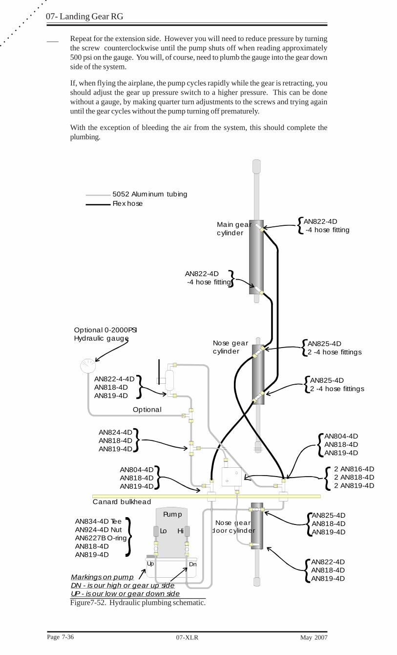
___ Repeat for the extension side. However you will need to reduce pressure by turningthe screw counterclockwise until the pump shuts off when reading approximately500 psi on the gauge. You will, of course, need to plumb the gauge into the gear downside of the system.
If, when flying the airplane, the pump cycles rapidly while the gear is retracting, youshould adjust the gear up pressure switch to a higher pressure. This can be donewithout a gauge, by making quarter turn adjustments to the screws and trying againuntil the gear cycles without the pump turning off prematurely.
With the exception of bleeding the air from the system, this should complete theplumbing.
Main gearcylinder
Nose gearcylinder
Nose geardoor cylinderLo Hi
AN834-4D TeeAN924-4D NutAN6227B O-ringAN818-4DAN819-4D
Pump
DnUp
Canard bulkhead
AN825-4DAN818-4DAN819-4D
AN822-4DAN818-4DAN819-4D
AN804-4DAN818-4DAN819-4D
2 AN816-4D2 AN818-4D2 AN819-4D
AN825-4D2 -4 hose fittings
AN822-4D -4 hose fitting
AN825-4D2 -4 hose fittings
AN822-4D -4 hose fitting
AN822-4-4DAN818-4DAN819-4D
AN824-4DAN818-4DAN819-4D
AN804-4DAN818-4DAN819-4D
Optional
Optional 0-2000PSIHydraulic gauge
5052 Aluminum tubingFlex hose
Markings on pumpDN - is our high or gear up sideUP - is our low or gear down sideFigure7-52. Hydraulic plumbing schematic.
07 - Landing Gear RG
May 2007 07-XLR Page 7-37
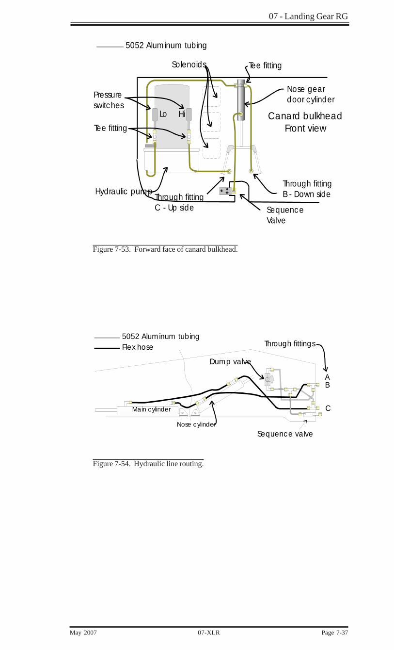
Lo Hi
Pressureswitches
Tee fitting
Tee fitting
Canard bulkheadFront view
Solenoids
Through fittingC - Up side
Through fittingB - Down side
Nose geardoor cylinder
Hydraulic pump
5052 Aluminum tubing
Sequence Valve
Figure 7-53. Forward face of canard bulkhead.
Main cylinder
Nose cylinder
5052 Aluminum tubingFlex hose
Sequence valve
Dump valve
AB
C
Through fittings
Figure 7-54. Hydraulic line routing.
07- Landing Gear RG
Page 7-38 07-XLR May 2007
○
○
○
○
○
○
○
○
○
○
○
○
○
Main gearmicro switch
Nose gearmicro switch
Throttlemicro switch
Hobbs
Pump running light(Red)
Main gear light(Green)
Nose gear light(Green)
Gear horn
#22#22
#22
#22
#22
#22
#18#18+
12 v
olt b
us
Optional
Lo H i
Pump
IS
IS
#12 Green
#12 Blue Black
#12 #1230Ampbreaker
Low
Hi
Red
Red
Blue
Blue
Down
All wires #18 unless specified.
Dim
Bright
Optional
Radio Shack#276-17715 volt regulator
Up
#22
#22
#18#18
#18
#18
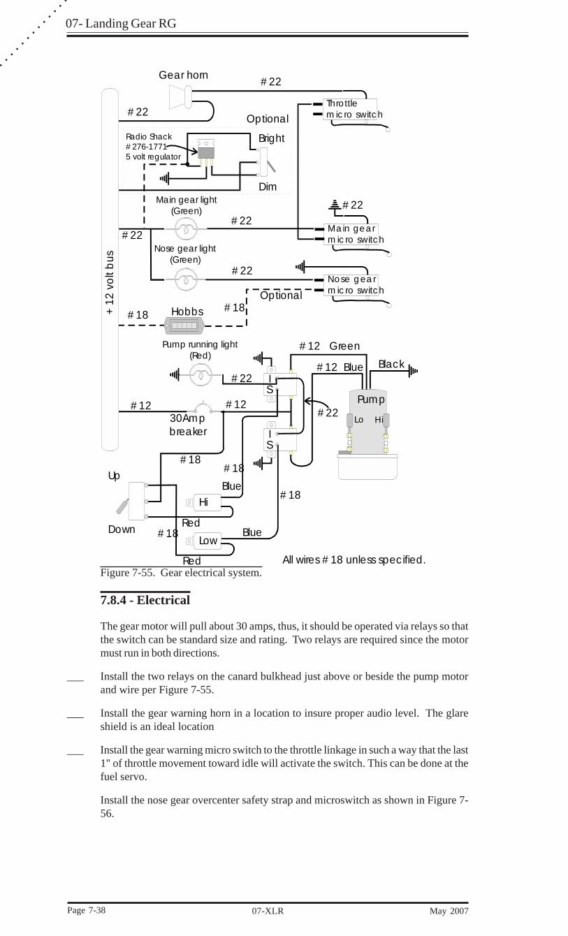
Figure 7-55. Gear electrical system.
7.8.4 - Electrical
The gear motor will pull about 30 amps, thus, it should be operated via relays so thatthe switch can be standard size and rating. Two relays are required since the motormust run in both directions.
___ Install the two relays on the canard bulkhead just above or beside the pump motorand wire per Figure 7-55.
___ Install the gear warning horn in a location to insure proper audio level. The glareshield is an ideal location
___ Install the gear warning micro switch to the throttle linkage in such a way that the last1" of throttle movement toward idle will activate the switch. This can be done at thefuel servo.
Install the nose gear overcenter safety strap and microswitch as shown in Figure 7-56.

07 - Landing Gear RG
May 2007 07-XLR Page 7-39
See Figure 7-55 for complete landing gear electrical detail.
.75"
4.687"
Overcenter stop and microswitch bracket detail - top view
Keel
Overcenter position - approximately¼" above horizontal
VASMS-01Switch bracket & stop
Microswitch
AN5-52A bolt
Drill to mount withMS35206-246 screwsMS21083-08 nuts
Forward
SwitchVMS-01
Figure 7-56. Overcenter microswitch detail.
Mount the microswitch on the forward, right side of the linkage so that it is activatedby the safety control arm. Position it so the switch is closed when the main gear isdown and locked. The overcenter stop that this microswitch mounts on is installed insection 7.8.5.
The main gear down microswitch is located on the main gear OC link. The lock armon the OC link actuates the micro switch when it locks in place.
Install the gear switch and lights on the instrument panel in easy view of the pilot.The gear switch has extra terminals to use as a Hobbs meter switch if desired, i.e.:wheels up activates Hobbs.
7.8.5 - Final System Adjustments
The gear down position must be determined first.
For the nose gear, you must adjust the linkage and shock to go overcenter about 1 to 2degrees (1/4”). The reason for this is in case of hydraulic failure, when loaded, thelinkage will be pulling on the cylinder, not pushing which would cause a collapse.Use a level finder on both the shock and linkage as you adjust the rod end to allowthis. After you have adjusted this right, screw the rod end all the way in and count thenumber of turns it takes. The reason for this is that you will have to remove this a fewtimes until you get the gear up position done. This way you won’t have to keepadjusting it every time you put it on.
When your cables are installed you set there tension for the down gear position.After the initial retract, you’ll need to readjust them because of cable stretch. For themain gear, the rod ends must be adjusted so the cables are snug but not tight to allowthe overcenter linkage to go straight. The gear up position can now be adjusted.

07- Landing Gear RG
Page 7-40 07-XLR May 2007
○
○
○
○
○
○
○
○
○
○
○
○
○
The gear-up adjustment for the nose and main gears is accomplished using spacers oneach cylinder shaft. (nose p/n: VASNGC-01, main p/m: VASMGC-01). You willprobably need to trim these spacers to create a physical stop between the large areawasher on the rod end and the main gear cylinder when the gear is fully retracted. Aneasy way to do this is to retract the gear up using the hydraulics. Be careful not to goto far and stretch your main gear cables. Stop the gear when your tires touch thetop of the wheel well. Check both gear legs because the arrangement can tetter allow-ing one but not both wheels to touch. When you are satisfied with your up positionmeasure the distance from the cylinder body to the stop washer. Cut your spacer tothis dimension. If your spacer is not long enough, add washers as shims between thespacer and stop nut.
Note: The main gear cylinder already has one wide area washer sandwiched atthe end as a bearing surface for the aluminum spacer.
It is important to have cylinders properly adjusted. The requirement is to have thecylinders bottom out against the spacer on the cylinder shafts. With the gears in theretracted position, the hydraulic pressure must not be putting a load onto the gearovercenter linkage but rather be carried by the spacer.
Warning: Do not add washers between the spacer and cylinder body as thiscould interfere with the downward travel and prevent the gear from lock-ing in the down position.
___ With the gear all the way retracted the spacer should have pressure on it. If you areable to rotate it with relative ease, then it is not doing its job and will require awasher as a shim.
___ With the main gears up where you want them, gear doors flush, fashion some rubberspacers to fit at the junction of the horizontal and transverse bulkheads so the gearsdon’t move side to side.
___ Adjust the sequence valve screw and nut so that it activates just as the gear is up inthe hole. This might take a little while to get right. Make sure it is not adjusted out sofar that it starts bending the attach bracket.
___ Test the main gear overcenter linkage locking arm for proper operation. Make sureno binding occurs that could cause it to jam. Follow this procedure:
With the aircraft on jacks, put the gear switch in the “UP” position. As soon as thenose gear starts up, pull the breaker to stop the pump. This will load the cables whilethe main linkage is still locked. By hand, move the locking arm up and down to checkfor smooth operation. Some filing of the slot on the arm may be necessary to achievesmoothness. After doing this, do a full retraction test to be sure everything worksproperly.
07 - Landing Gear RG
May 2007 07-XLR Page 7-41
7.9 - Emergency Extension
7.9.1 - Basics
When the landing gear is retracted in a Velocity it is held up in place by hydraulicpressure. There is a dump valve that is located between the high pressure side (up)and the low pressure side (down) in the Velocity gear system. In the event you havean electrical failure you can lower the gear by opening the dump valve. The maingear will positively lock in to their down position by gravity alone. The nose geardoors have springs installed on the cylinder to help open the doors during an emer-gency extension. The nose gear has a 90 lb. gas spring installed on the overcenterlinkage to help it lock into its overcenter position during an emergency extension.Once the nose gear clears the doors as it is dropping it will also have wind loads tohelp push it into position.
7.9.2 - Nose Gear Safety Stick
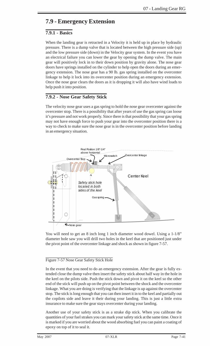
The velocity nose gear uses a gas spring to hold the nose gear overcenter against theovercenter stop. There is a possibility that after years of use the gas spring can looseit’s pressure and not work properly. Since there is that possibility that your gas springmay not have enough force to push your gear into the overcenter position there is away to check to make sure the nose gear is in the overcenter position before landingin an emergency situation.
You will need to get an 8 inch long 1 inch diameter wood dowel. Using a 1-1/8”diameter hole saw you will drill two holes in the keel that are positioned just underthe pivot point of the overcenter linkage and shock as shown in figure 7-57.
Figure 7-57 Nose Gear Safety Stick Hole
In the event that you need to do an emergency extension. After the gear is fully ex-tended close the dump valve then insert the safety stick about half way in the hole inthe keel on the pilots side. Push the stick down and pivot it on the keel so the otherend of the stick will push up on the pivot point between the shock and the overcenterlinkage. What you are doing is verifying that the linkage is up against the overcenterstop. The stick is long enough that you can then insert it in to the keel and partially outthe copilots side and leave it their during your landing. This is just a little extrainsurance to make sure the gear stays overcenter during your landing.
Another use of your safety stick is as a strake dip stick. When you calibrate thequantities of your fuel strakes you can mark your safety stick at the same time. Once itis marked if you are worried about the wood absorbing fuel you can paint a coating ofepoxy on top of it to seal it.
Nose gear
Overcenter linkage
Gas spring
Final Position 1/8"-1/4" above horizontal
Center Keel
Overcenter StopMicroswitch
Safety stick holelocated in both sides of the keel
07- Landing Gear RG
Page 7-42 07-XLR May 2007
○
○
○
○
○
○
○
○
○
○
○
○
○
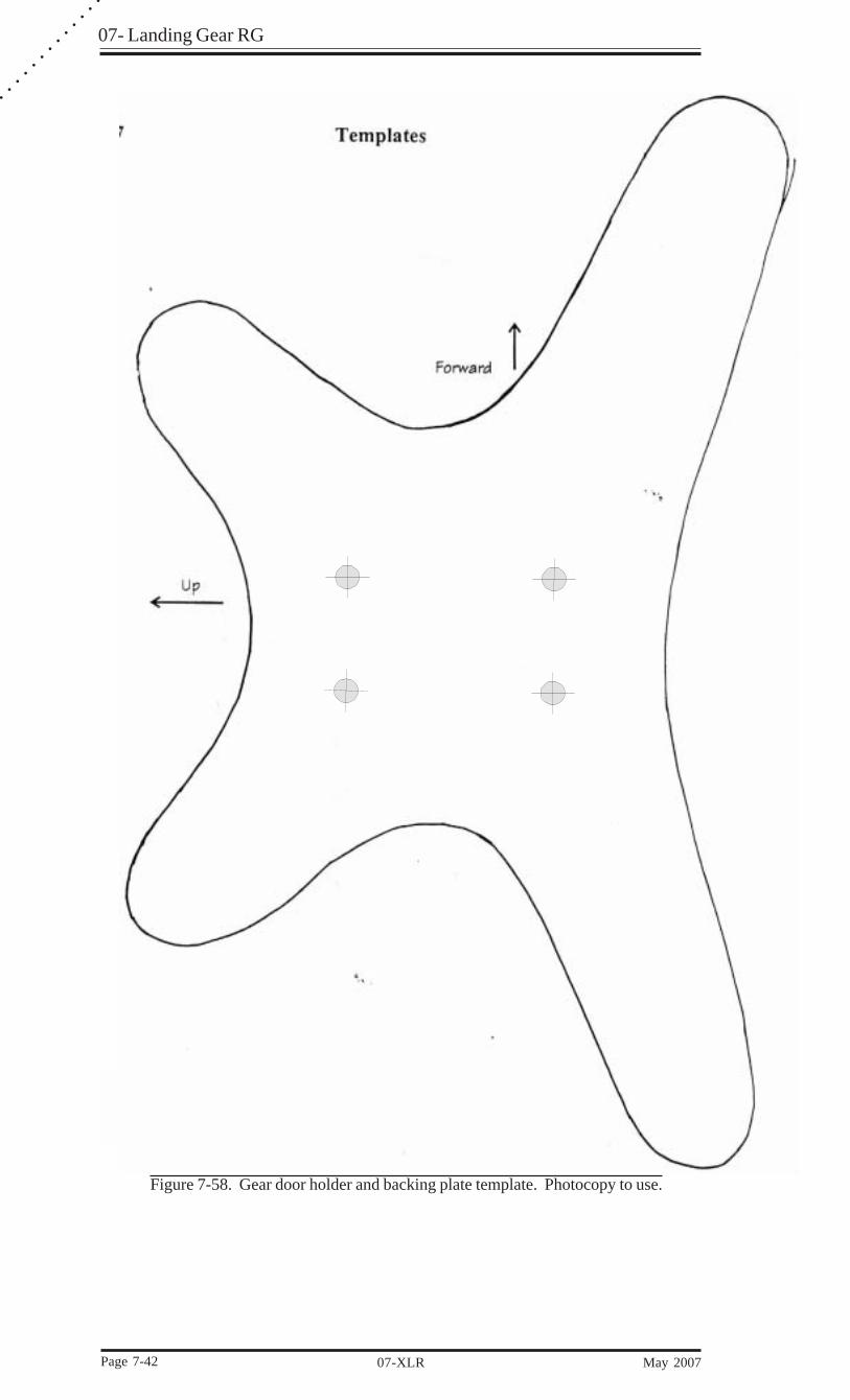
Figure 7-58. Gear door holder and backing plate template. Photocopy to use.

07 - Landing Gear RG
May 2007 07-XLR Page 7-43
Spa
rH
orizo
ntal b
ulkhea
d
Gear bulkhead
Firewall
Bend
in bulkhe
ad
173 Cut line
- 5-3/8" high
Stand
ard
wing
cut line - 6-7/8" high
Transve
rse Bulkhe
ad
1/4“ Foa
mM
ake
2
Figure 7-59. Transverse bulkhead template. Photocopy to use.
07- Landing Gear RG
Page 7-44 07-XLR May 2007
○
○
○
○
○
○
○
○
○
○
○
○
○
No
Mor
e th
an a
n 1/
8“ o
ff t
he F
loor
Pulley cut-out in gear bulkhead
CLCentered
Aluminumstrip
(supplied)
Figure 7-60. Pulley cutout template. Photocopy to use.
Floor
Ge
ar b
ulkh
ea
dUp
Forward
¼" plywood
(Make 2)
Figure 7-61. Main gear pulley support template. Photocopy to use.
![Landing Gear Accessories - goldlinequalityparts.com€¦ · 12 Landing Gear Accessories Landing Gear Accessories 13 [254.0mm] 10.00" [254.0mm] 10.00" [111.3mm] 4.38" [304.8mm] 12.00"](https://static.documents.pub/doc/80x56/5f42201687106b11477aac9b/landing-gear-accessories-12-landing-gear-accessories-landing-gear-accessories.jpg)


![arXiv:1407.0927v1 [cs.SE] 3 Jul 2014Landing-Gear Extended Landing-Gear Retracted Landing-Gear Box Landing Wheel Door Figure 1: Landing Gear System such as airport runways [11]. Three](https://static.documents.pub/doc/80x56/5e9397289f16a23cdf089611/arxiv14070927v1-csse-3-jul-2014-landing-gear-extended-landing-gear-retracted.jpg)