Landslide Mobility and Flexible Barrier Numerical Modelling Using LS-DYNA Jack Yiu, Yuli Huang, Jack Pappin, Richard Sturt Arup, Hong Kong Julian S. H. Kwan & Ken K. S. Ho Geotechnical Engineering Office, Civil Engineering and Development Department ABSTRACT Driven by the initiative of the Geotechnical Engineering Office (GEO), Civil Engineering and Development Department, Arup is undertaking a pilot numerical investigation of debris/flexible barrier interaction. The 3D multi-purpose finite element program LS-DYNA has been adopted for numerical analyses. This paper presents the modelling methodology for debris mobility and the simulation technique adopted for the modelling of flexible barrier structure using LS-DYNA. At the time of preparing this paper, modelling of USGS laboratory flume tests, full scale rockfall tests, and the trial simulation of 2008 Yu Tung Road Debris Flow have been completed. Preliminary simulation results as well as the way forward of this ongoing Study are presented in this paper. Keywords: Flexible barriers; debris mobility modelling 1 INTRODUCTION Hong Kong has a high proportion of land area that consists of relatively steep natural terrain. This land area is susceptible to landslides that can travel long distances and can pose a significant hazard to the development in the vicinity of the natural hillsides. Flexible barriers could be a feasible option for mitigating the natural landslide risk. Proprietary flexible rockfall protection barriers with or without modifications have recently been proposed to resist debris flows and open hillside landslides. It has been shown in some overseas studies that these flexible barriers are capable of stopping and retaining a certain amount of landslide debris. Very often, debris-resisting flexible barrier is an attractive option since the barrier construction involves relatively lightweight plant and materials, which can greatly facilitate construction in hilly terrain and it is less obstructive environmentally and visually. An example of such barrier that has been installed in Hong Kong is shown in Plate 1. Plate 1: A flexible barrier setup at the Hong Kong University of Science and Technology. Despite the merits mentioned above, a comprehensive and recognised design standard for flexible debris- resisting barriers is lacking. The development of such a design standard and appropriate design methodology for flexible barriers requires an understanding of both landslide dynamics and the interaction of landslide 1
Transcript
Landslide Mobility and Flexible Barrier Numerical Modelling Using LS-DYNA
Jack Yiu, Yuli Huang, Jack Pappin, Richard Sturt Arup, Hong Kong
Julian S. H. Kwan & Ken K. S. Ho Geotechnical Engineering Office, Civil Engineering and Development Department
ABSTRACT
Driven by the initiative of the Geotechnical Engineering Office (GEO), Civil Engineering and Development Department, Arup is undertaking a pilot numerical investigation of debris/flexible barrier interaction. The 3D multi-purpose finite element program LS-DYNA has been adopted for numerical analyses. This paper presents the modelling methodology for debris mobility and the simulation technique adopted for the modelling of flexible barrier structure using LS-DYNA. At the time of preparing this paper, modelling of USGS laboratory flume tests, full scale rockfall tests, and the trial simulation of 2008 Yu Tung Road Debris Flow have been completed. Preliminary simulation results as well as the way forward of this ongoing Study are presented in this paper.
Hong Kong has a high proportion of land area that consists of relatively steep natural terrain. This land area is susceptible to landslides that can travel long distances and can pose a significant hazard to the development in the vicinity of the natural hillsides. Flexible barriers could be a feasible option for mitigating the natural landslide risk. Proprietary flexible rockfall protection barriers with or without modifications have recently been proposed to resist debris flows and open hillside landslides. It has been shown in some overseas studies that these flexible barriers are capable of stopping and retaining a certain amount of landslide debris. Very often, debris-resisting flexible barrier is an attractive option since the barrier construction involves relatively lightweight plant and materials, which can greatly facilitate construction in hilly terrain and it is less obstructive environmentally and visually. An example of such barrier that has been installed in Hong Kong is shown in Plate 1.
Plate 1: A flexible barrier setup at the Hong Kong University of Science and Technology.
Despite the merits mentioned above, a comprehensive and recognised design standard for flexible debris-resisting barriers is lacking. The development of such a design standard and appropriate design methodology for flexible barriers requires an understanding of both landslide dynamics and the interaction of landslide
1
edms
Text Box
debris and flexible barriers. Driven by the initiative of the Geotechnical Engineering Office (GEO), Civil Engineering and Development Department, Arup is undertaking a pilot numerical investigation of the debris/flexible barrier interaction. Such modelling work is technically challenging as it calls for coupling of debris mobility analysis and structural assessment of flexible barrier. The multi-purpose finite element program, LS-DYNA, has been used to carry out the coupled analysis.
2 THE STUDY
2.1 The framework
Although the simulation of debris mobility and the structural modelling of flexible barriers have been successfully carried out separately by various people in the past, the coupled modelling of both remains a challenge and has yet to be done. In order to achieve a complete modelling of debris flow impacting on a flexible barrier, it is necessary to identify an appropriate computer program with the correct modelling techniques and choice of material properties. In this Study, the modelling work is divided into different stages. This approach also allows for review of interim results and necessary adjustments on the strategy of the investigation for subsequent stages. The stages are as follows:
i. Selection of the computer program;ii. Simulation of rockfall field test;
iii. Simulation of laboratory flume tests and real debris flow cases in Hong Kong;iv. Simulation of an instrumented case of debris flow impacting a flexible barrier; andv. Parametric study of different sizes and velocities of debris flow impacting a flexible barrier.
At the time of preparing this paper, the stage (i) & (ii) work is complete and the stage (iii) work is in progress with trial runs for two out of three of the selected simulation cases completed.
2.2 Choice of the computer program - LS-DYNA
LS-DYNA is a multi-purpose finite element program used to analyse the nonlinear response of structures. Its fully automated contact analysis and wide range of material models enable the solving of complex real world problems such as automotive crash analysis, metal forming, drop testing, seismic analysis and blast loading. It has the capability to analyse multi-physics problems such as fluid-structure interaction, and thermal-structure coupling. LS-DYNA has also been used extensively in civil engineering related design and analysis, including rail, civil, structural, wind and vibration engineering. Due to its ability to simulate large-scale deformation and the vast choices of non-linear material behaviour, it was chosen as the computer program for the Study.
3 PRELIMINARY RESULTS OF THE ROCKFALL FIELD TEST SIMULATION
3.1 General
Because of the highly flexible nature of the barrier, it is crucial that the numerical simulation adopted would be able to handle non-linear material behaviour and large deformation of individual structural components. Therefore a benchmarking exercise has been carried out based on the field tests conducted by the Swiss Institute for Snow and Avalanche Research (SLF Davos) on flexible barriers, originally reported by Grassl (2002) and later in the PhD thesis on Numerical Simulation of Flexible Rockfall Protection Systems by Volkwein (2004).
Among different test set-ups reported by Volkwein (2004), it was decided that tests on the movable positioned ring net (Plate 2) be adopted for the benchmarking exercise. This flexible net was made of 300 mm diameter rings which were formed by 7 nos. winding of steel wires. These rings were able to slide freely against each other. The flexible ring net was connected to prestressed steel cables via shackles. These shackles allowed the edge rings to move along the cable direction. The steel cables were supported by the beams of the steel rigs and are anchored to a concrete block on the ground at the ends.
2
To simulate the rockfall scenarios, an 820 mm diameter ball made of steel fibre reinforced concrete was adopted as the weight. The total mass of the weight was 825 kg. Tests were performed with the concrete ball dropping at different heights (16 m & 32 m) and the test rigs were equipped with or without brake rings. The performance and the non-linear behaviour of different structural components of the flexible barrier were studied in the numerical simulation.
Plate 2: The specifically-built test rig for rock fall tests (Extracted from Volkwein, 2004)
3.2 The LS-DYNA simulation
In the LS-DYNA simulation, all structural components were modelled explicitly using beam elements, whereas the concrete ball was modelled as a rigid sphere. Non-linear load-deformation relationship curves were specified for some of the structural components such as the steel rings and brake rings that exhibited highly non-linear behaviours. No specific test data were available for the contact friction between different components of the test rigs. Based on engineering judgement, a friction coefficient of µ = 0.1 was adopted for all material contacts.
The model was initialised by applying gravity load to the test rigs, structural components of the flexible barrier, as well as the concrete ball. The concrete ball was then allowed to fall freely and impact on the flexible barrier. The position, velocity and potential energy of the concrete ball were tracked and recorded. The deformation of the ring net and the movement of the steel cables were calculated. In addition, the tension forces developed within the steel cables were tracked and recorded for comparison with the test data.
The position and total energy of the ball respect to time were compared between the LS-DYNA simulation and the rockfall field tests. These results for the cases of 16 m drop without brake rings and 16 m / 32 m drop with brake rings are shown in Figures 1 to 4. Time = 0 second represents the moment when the ball reached the elevation of the test rig beams. The LS-DYNA simulation also provided the visual illustration of the deformation of the flexible barrier during the impact of the rockfall, as shown in Figure 5.
3.4 Discussion
As demonstrated in Figure 1, the explicit modelling of the structural components in LS-DYNA, for example, steel rings and shackles, enables the accurate prediction on the movement of the ring net and the plastic deformation of rings. The extension and sideways movement of the steel cables have also been predicted accurately being very similar to the actual tested barrier.
Figures 2 and 3 demonstrate that the LS-DYNA simulation was able to predict the concrete ball displacement for both cases, i.e. with and without brake rings. The estimated energy dissipation of the concrete ball by LS-DYNA also agreed with those measured in the test (Figure 4 and 5). The accurate prediction by LS-DYNA implies that the structural modelling of the flexible barrier is able to replicate the non-linear behaviour of the structural components, with the relationship between deformation and energy dissipation correctly implemented.
3
Time elapsed, t = 0.00s Time elapsed, t = 0.10s
Time elapsed, t = 0.20s Time elapsed, t = 0.35s
Time elapsed, t = 0.40s Time elapsed, t = 0.80s
Time elapsed, t = 1.00s Time elapsed, t = 1.20s
Figure 1: Simulated deformation of the flexible barrier during the 16 m drop rock fall test with brake rings (steel frame of the test rig not shown for clarity) simulation
Figure 2 (left): Displacement-time curves of 16 m drop case (both with and without brake rings)
Figure 3 (right): Displacement-time curves of 16 m and 32 m drop cases (both with brake rings)
4
Figure 4 (left): Total energy - time curves of 16 m drop case (both with and without brake rings)
Figure 5 (right): Total energy - time curves of 16 m and 32 m drop cases (both with brake rings)
4 PRELIMINARY RESULTS OF DEBRIS FLOW SIMULATION
4.1 General
In order to identify the appropriate numerical techniques, constitutive models and rheological parameters for modelling debris mobility for the study of the interaction between landslide debris and flexible debris-resisting barrier, it is necessary to benchmark the proposed numerical model against instrumented tests or case histories. The following cases were chosen:
i. The experimental tests on granular avalanches across irregular three-dimensional terrains reported byIverson et al. (2004) (referred to as the USGS laboratory flume tests in this paper);
The USGS laboratory flume tests reported by Iverson et al (2004) consisted of two experiments, viz. Experiment A and Experiment B, carried out in a bench top flume of 0.2m wide and approximately 1m long. The steep part of the flume was fitted with a urethane insert to form an irregular basal surface as the 'topography'. Two types of dry sand materials, one angular and the other rounded, were used for the flume tests. A head gate was installed at the upslope section for storage of the static dry sand, which enabled an instant release of the static granular mass. A summary of experiment conditions and sand properties is given in Table 1. Digital photography and laser cartography were adopted for capturing the movement of the avalanches during the experiments.
Table 1: Summary of experiment conditions and sand properties (Iverson et. al, 2004)
The Yu Tung Road landslide on Lantau Island, Hong Kong was triggered by an estimated 1 in 600 year return period rainstorm on 7 June 2008. The channelised debris flow travelled over 500 m and blocked the west bound carriageway of Yu Tung Road with about 3,000 m3 of debris (Tattersall et al, 2009). Mapping and laser survey were carried out to determine the profile and morphology of the source area and the debris trail. The occurrence of the landslide was captured by a video (referred to as the 'You Tube Video'), which provides information on the nature of the of the debris flow characteristic, the debris trail and the debris flow speed.
4.4 LS-DYNA simulation
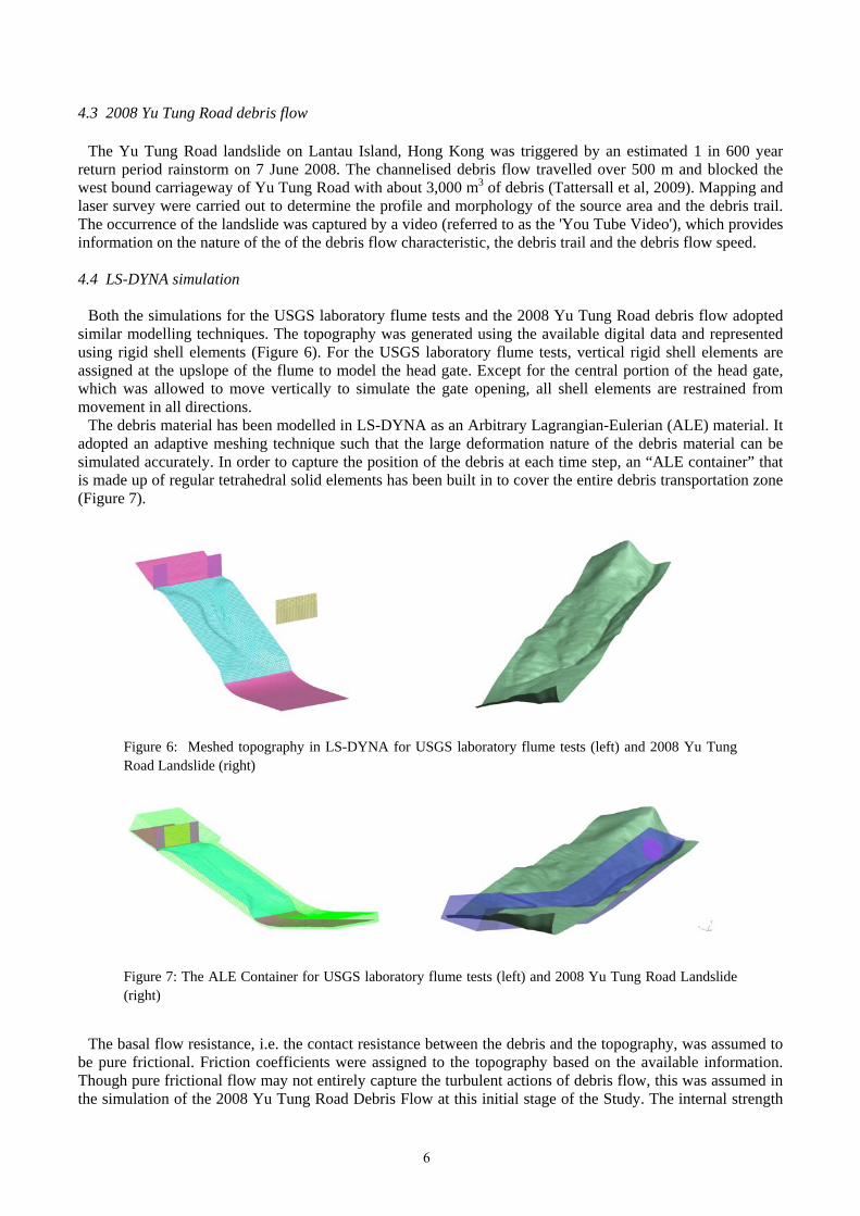
Both the simulations for the USGS laboratory flume tests and the 2008 Yu Tung Road debris flow adopted similar modelling techniques. The topography was generated using the available digital data and represented using rigid shell elements (Figure 6). For the USGS laboratory flume tests, vertical rigid shell elements are assigned at the upslope of the flume to model the head gate. Except for the central portion of the head gate, which was allowed to move vertically to simulate the gate opening, all shell elements are restrained from movement in all directions.
The debris material has been modelled in LS-DYNA as an Arbitrary Lagrangian-Eulerian (ALE) material. It adopted an adaptive meshing technique such that the large deformation nature of the debris material can be simulated accurately. In order to capture the position of the debris at each time step, an “ALE container” that is made up of regular tetrahedral solid elements has been built in to cover the entire debris transportation zone (Figure 7).
Figure 6: Meshed topography in LS-DYNA for USGS laboratory flume tests (left) and 2008 Yu Tung Road Landslide (right)
Figure 7: The ALE Container for USGS laboratory flume tests (left) and 2008 Yu Tung Road Landslide (right)
The basal flow resistance, i.e. the contact resistance between the debris and the topography, was assumed to be pure frictional. Friction coefficients were assigned to the topography based on the available information. Though pure frictional flow may not entirely capture the turbulent actions of debris flow, this was assumed in the simulation of the 2008 Yu Tung Road Debris Flow at this initial stage of the Study. The internal strength
6
of the debris material was specified by assigning a set of apparent total stress strength parameters in terms of friction angle and cohesion. The Drucker-Prager yield criteria have been adopted. For the USGS laboratory flume tests, the above parameters were directly taken from the data provided by Iverson et al. (2004), whereas for the 2008 Yu Tung Road debris flow, the simulation was repeated with different contact friction and debris mass internal friction. They have been adjusted to match the observed flow characteristics (e.g. thickness and length of debris mass) and flow speed. Entrainment and some secondary slides which were observed in the 2008 Yu Tung Road debris flow were not modelled.
4.6 USGS laboratory flume test simulation results
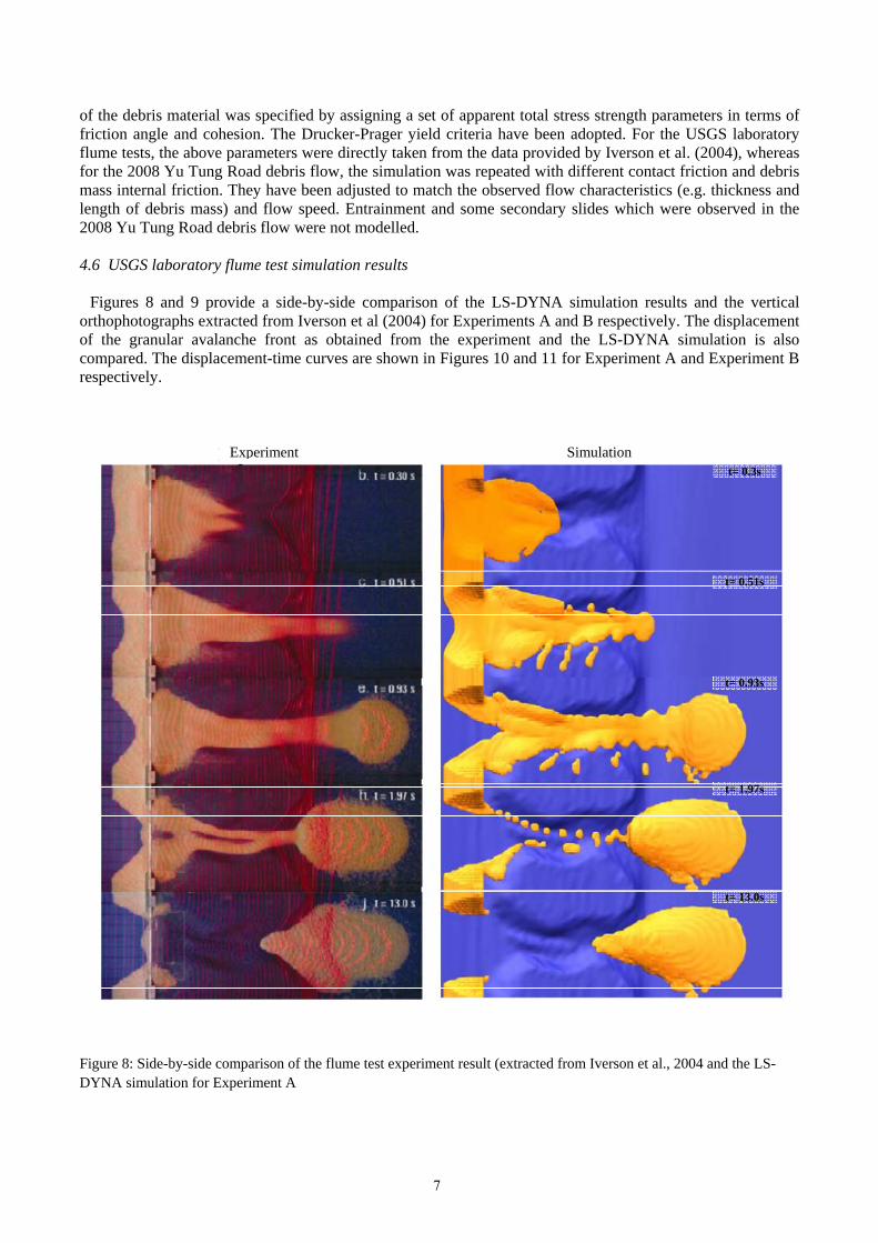
Figures 8 and 9 provide a side-by-side comparison of the LS-DYNA simulation results and the vertical orthophotographs extracted from Iverson et al (2004) for Experiments A and B respectively. The displacement of the granular avalanche front as obtained from the experiment and the LS-DYNA simulation is also compared. The displacement-time curves are shown in Figures 10 and 11 for Experiment A and Experiment B respectively.
Figure 8: Side-by-side comparison of the flume test experiment result (extracted from Iverson et al., 2004 and the LS-DYNA simulation for Experiment A
t= 0.51s
t= 0.3s
t= 0.93s
t= 1.97s
t= 13.0s
Experiment Simulation
7
Figure 9: Side-by-side comparison of the flume test experiment result (extracted from Iverson et al., 2004 and the LS-DYNA simulation for Experiment B
Figure 10 (left): Frontal displacement-time curves of the granular avalanches obtained from the experimental results and the LS-DYNA simulation for Experiment A
Figure 11 (right): Frontal displacement-time curves of the granular avalanches obtained from the experimental results and the LS-DYNA simulation for Experiment B
Figure 12 shows snap shots of a LS-DYNA debris flow simulation at selected time steps.
Figure 12: Selected snap shots of LS-DYNA simulation for the 2008 Yu Tung Road debris flow
Figure 13 shows the frontal displacement against time plot for various combinations of debris internal friction angles and basal friction angles. From the video, it was evident that the debris travelled from chainage 320 m to 530 m in approximately 20 to 21 seconds, which was equivalent to an average velocity of about 10 m/s. These two chainages have been highlighted in the plot for reference. It can be seen that the combination of internal friction angle of 1.25 degree and contact friction of 25degree (run 19 in the study) provides the best estimation of the debris mobility among all runs in terms of the average velocity moving f chainage 320 m and 530 m. In addition, it was observed from the video that the landslide debris was highly saturated and fluid-like. The use of low internal friction enables the simulation of the fast moving debris even on relatively gentle terrain, for example near the crest of the man-made cut slope next to Yu Tung Road carriageway.
Figure 13: Frontal displacement vs. time plot
T =0 s T =10 s
T =20 s T =40 s
0
100
200
300
400
500
600
700
0 10 20 30 40 50 60
Horizontal Chainage of Debris Front (m
)
Time (seconds)
Run 13 (fb = 25 deg, f = 5 deg)
Run 14 (fb = 30 deg, f = 5 deg)
Run 15 (fb = 20 deg, f = 10 deg)
Run 19 (fb = 25 deg, f = 1.25 deg)
Run 22 (fb =15 deg, f = 10 deg)
chainage 530
chainage 320
9
4.8 Discussion
4.8.1 USGS laboratory flume tests simulation
From the side-by-side result comparison given in Figures 8 and 9 it can be seen that the LS-DYNA simulation generally matched the test results very well for both Experiments A and B in terms of the movement with respect to time and the deposition extent. In addition the simulations were able to predict the development of the sand prisms behind the head gate after some of the granular avalanches have been released through the opening and run down the slope.
For both Experiments A and B, which the predicted frontal displacement and experiment measurement match reasonably well, as shown Figure 10 and 11, it can be seen that the simulation produced a slightly shorter displacement of the granular avalanches at about 0.5 s in Experiment B. This was probably because the phenomenon of spreading of a thin layer of the granular avalanche at the front was more pronounced in this case. It was likely to be a consequence of using spherical sand which has a relatively strong tendency to spread out as noted by Iverson et al (2004). The sand was much diffused at the front and therefore was not picked up by the LS-DYNA analysis. The result could be improved if a higher resolution ALE container was adopted.
4.8.2 2008 Yu Tung Road debris flow simulation
The preliminary simulation work carried out so far indicates that LS-DYNA is a promising numerical tool for modelling debris flows. Reasonable simulation of the debris flow has been produced, though more work is needed to validate the parameters used.
As compared with other commonly adopted numerical modelling technique for debris mobility assessment, LS-DYNA is a full 3D finite element analysis, which considers the effect of internal stress and strains, whereas the other techniques adopt a simplified depth-averaged approach and consider external stresses and internal stresses, calculated based on simple lateral earth pressure models, applied on the discretised blocks or columns of debris mass. Direct comparison of the parameters used in these methods against LS-DYNA's parameters is therefore not appropriate. Certain modelling methodologies, such as the use of Voellmy rheology, may require modification and adjustment before it can be applied in LS-DYNA.
5 WAY FORWARD
5.1 Possibility of using Voellmy rheology in LS-DYNA
The simulation work completed so far reveals that the pure friction model adopted in LS-DYNA analysis could produce reasonable frontal velocity results. Nonetheless, it has been well recognised from various experiments and observations that resistance to landslide debris movement could be velocity dependent. This relationship could be described by Voellmy rheology and has been adopted in various computer program packages.
Since LS-DYNA is a more sophisticated finite element program, use of Voellmy rheology in LS-DYNA's analysis may not necessarily give the similar results produced by other debris mobility models. However, with certain modifications and adjustments, for example by relating the resistance with the internal shear strain rate, as mentioned by Hungr (1995) in relation to the findings of Bagnold (1954), LS-DYNA may be able to capture the phenomenon of velocity-dependent basal resistance. This would allow the use of LS-DYNA for more in-depth study of debris flows and further comparisons with other computer programs.
5.2 Debris-Structure interaction and associated parametric study
As the primary objective of the study is to provide insight on the interaction between landslide debris and flexible barrier structures, it is essential to carry out simulation on an instrumented and well documented case of landslide debris impacting flexible barriers. With the current modelling technique adopted in LS-DYNA for the flexible steel ring net, some modifications would be required. An initial investigation has suggested that the use of an imaginary membrane, with negligible stiffness, covering the openings would enable effective transmission the debris impact load to the flexible barrier structures. Once this is tested and proven with the
10
selected benchmark case, a parametric study can be undertaken to investigate the debris-structure interaction of different volume of debris mass travelling at different velocities.
6 CONCLUSION
The present study has explored the appropriate numerical analysis technique to investigate the interaction of landslide debris and flexible barrier. The work done so far indicates that a multi-purpose 3D finite element program, such as LS-DYNA, is capable of modelling the highly non-linear behaviour of the structural components of the flexible barrier structures as well as the large deformation of debris mass. It highlights the potential of using such computer programs to obtain a better understanding of the mechanics of the landslide debris as well as its interaction with flexible barrier. The requirements for further study have been identified with the focus on the development of Voellmy rheology module in LS-DYNA and the simulation of a documented case of landslide debris impacting on a flexible barrier structure. It is hoped that further findings obtained from the study would provide useful insights for the analytical design of flexible debris-resisting barriers.
ACKNOWLEDGEMENTS
This paper is published with the permission of the Head of the Geotechnical Engineering Office and the Director of the Civil Engineering and Development, Government of the Hong Kong Special Administrative Region.
REFERENCES
Grassl H.G. (2002), Experimentelle und numerische Modellierung des dynamischen Frag- und Vergormungsverhaltens von hochflexiblen Schutzsystemen gegen Steinschlag, Thesis for Doctor of Technical Science of the Swiss Federal Institute of Technology Zurich Grassl H.G., Volkwein A.K.H. & Bartelt P. (2003), Experiment and numerical modelling of highly flexible rockfall protection barriers, Proc. Soil and Rock America 2003, Cambridge, Massachusetts Hungr O. (1995), A model for the runout analysis of rapid flow slides, debris flows and avalanches, Canadian Geotechnical Journal, 32, 610-623 Iverson R. M., Logan M. & Denlinger R. P. (2004), Granular avalanches across irregular three-dimensional terrain: 2. Experimental tests, Journal of Geophysical Research, 109, F01015, doi:10.1029/2003JF000084 Livermore Software Technology Corporation (2012), LS-DYNA® Keyword user’s manual, Version 971 R6.0.0, Volume I & II Lo. D.O.K. (2000), Review of natural landslide debris-resisting barrier design, GEO Report No.104, Geotechnical Engineering Office, Civil Engineering and Development Department, Government of Hong Kong Special Administrative Region Sun H.W. (2007), Benchmarking exercise on landslide runout analysis review findings, Presentation for 2007 International Forum on Landslide Disaster Management, Day 3 Tattersall J.W., Devonald D.M. & McDougall S. (2009), Modelling of Debris Flows for the North Lantau Experssway and Yu Tung Road Study Area, Proceedings of the 29th Annual Seminar - Natural Hillsides: Study and Risk Mitigation Measures, Geotechnical Division, The Hong Kong Institution of Engineers, 163-169 Volkwein A. K. H. (2004), Numerical simulation of flexible rockfall protection systems, Thesis for Doctor of Technical Sciences of the Swiss Federal Institute of Technology Zurich. Zhou Z.H., Liu Y.P. & Chan S.L. (2011), Nonlinear finite element analysis and design of flexible barrier, Hong Kong Polytechnics University