Lanthanide-Assisted Deposition of Strongly Electro-optic PZT ThinFilms on Silicon: Toward Integrated Active Nanophotonic DevicesJ. P. George,*,†,‡,∥ P. F. Smet,§,∥ J. Botterman,§,∥ V. Bliznuk,⊥ W. Woestenborghs,†,∥ D. Van Thourhout,‡,∥
K. Neyts,†,∥ and J. Beeckman†,∥
†Department of Electronics and Information Systems, Ghent University, Sint-Pietersnieuwstraat 41, 9000 Gent, Belgium‡Department of Information Technology, Ghent University, Sint-Pietersnieuwstraat 41, 9000 Gent, Belgium§LumiLab, Department of Solid State Sciences, Ghent University, Krijgslaan 281-S1, 9000 Gent, Belgium∥Center for Nano- and Biophotonics (NB-Photonics), Ghent University, 9000 Gent, Belgium⊥Department of Materials Science and Engineering, Ghent University, Technologiepark 903, B-9052 Zwijnaarde, Belgium
*S Supporting Information
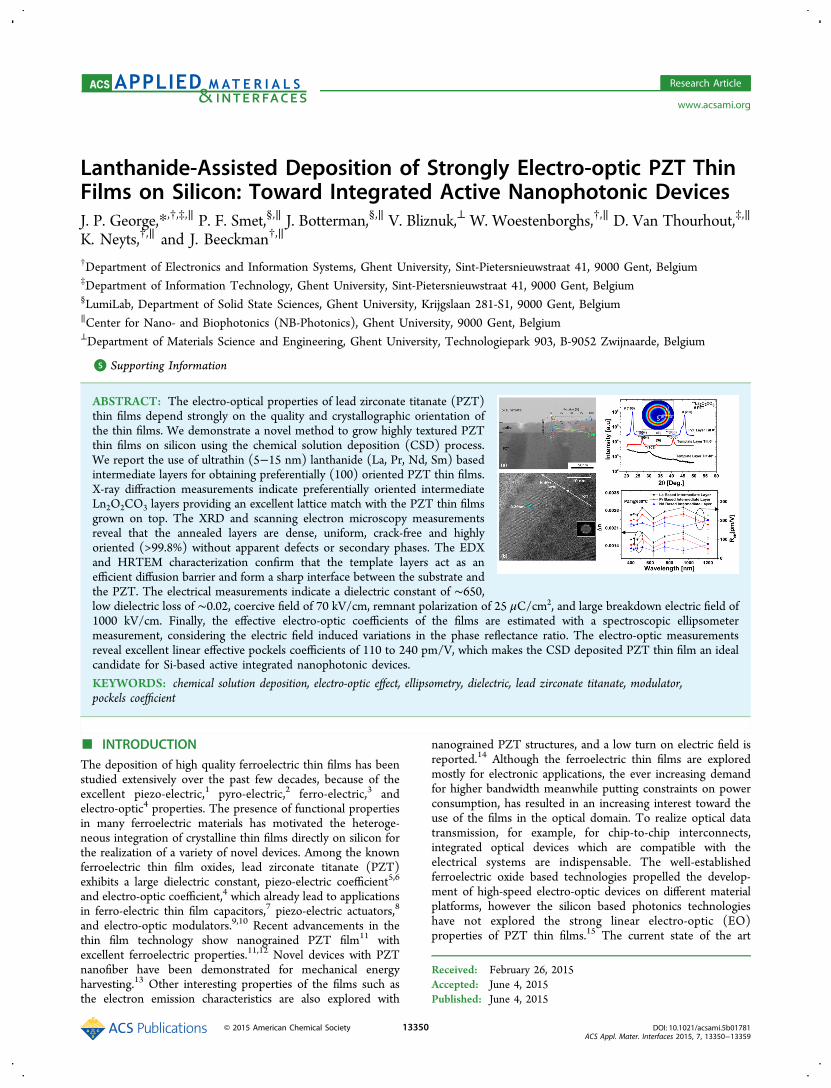
ABSTRACT: The electro-optical properties of lead zirconate titanate (PZT)thin films depend strongly on the quality and crystallographic orientation ofthe thin films. We demonstrate a novel method to grow highly textured PZTthin films on silicon using the chemical solution deposition (CSD) process.We report the use of ultrathin (5−15 nm) lanthanide (La, Pr, Nd, Sm) basedintermediate layers for obtaining preferentially (100) oriented PZT thin films.X-ray diffraction measurements indicate preferentially oriented intermediateLn2O2CO3 layers providing an excellent lattice match with the PZT thin filmsgrown on top. The XRD and scanning electron microscopy measurementsreveal that the annealed layers are dense, uniform, crack-free and highlyoriented (>99.8%) without apparent defects or secondary phases. The EDXand HRTEM characterization confirm that the template layers act as anefficient diffusion barrier and form a sharp interface between the substrate andthe PZT. The electrical measurements indicate a dielectric constant of ∼650,low dielectric loss of ∼0.02, coercive field of 70 kV/cm, remnant polarization of 25 μC/cm2, and large breakdown electric field of1000 kV/cm. Finally, the effective electro-optic coefficients of the films are estimated with a spectroscopic ellipsometermeasurement, considering the electric field induced variations in the phase reflectance ratio. The electro-optic measurementsreveal excellent linear effective pockels coefficients of 110 to 240 pm/V, which makes the CSD deposited PZT thin film an idealcandidate for Si-based active integrated nanophotonic devices.
KEYWORDS: chemical solution deposition, electro-optic effect, ellipsometry, dielectric, lead zirconate titanate, modulator,pockels coefficient
■ INTRODUCTIONThe deposition of high quality ferroelectric thin films has beenstudied extensively over the past few decades, because of theexcellent piezo-electric,1 pyro-electric,2 ferro-electric,3 andelectro-optic4 properties. The presence of functional propertiesin many ferroelectric materials has motivated the heteroge-neous integration of crystalline thin films directly on silicon forthe realization of a variety of novel devices. Among the knownferroelectric thin film oxides, lead zirconate titanate (PZT)exhibits a large dielectric constant, piezo-electric coefficient5,6
and electro-optic coefficient,4 which already lead to applicationsin ferro-electric thin film capacitors,7 piezo-electric actuators,8
and electro-optic modulators.9,10 Recent advancements in thethin film technology show nanograined PZT film11 withexcellent ferroelectric properties.11,12 Novel devices with PZTnanofiber have been demonstrated for mechanical energyharvesting.13 Other interesting properties of the films such asthe electron emission characteristics are also explored with
nanograined PZT structures, and a low turn on electric field isreported.14 Although the ferroelectric thin films are exploredmostly for electronic applications, the ever increasing demandfor higher bandwidth meanwhile putting constraints on powerconsumption, has resulted in an increasing interest toward theuse of the films in the optical domain. To realize optical datatransmission, for example, for chip-to-chip interconnects,integrated optical devices which are compatible with theelectrical systems are indispensable. The well-establishedferroelectric oxide based technologies propelled the develop-ment of high-speed electro-optic devices on different materialplatforms, however the silicon based photonics technologieshave not explored the strong linear electro-optic (EO)properties of PZT thin films.15 The current state of the art
Received: February 26, 2015Accepted: June 4, 2015Published: June 4, 2015
high-speed integrated optical devices are based on LiNbO3single crystals.16 However, replacing them with ferroelectricthin film oxides such as PZT, along with the compact siliconphotonic platform, could be an alternative to realize smaller,functional and power efficient devices.10,17−19
A variety of methods has been used to develop ferroelectricthin films: chemical solution deposition (CSD),20 RF magnet-ron sputtering,21 metal organic chemical vapor deposition(MOCVD)22 and pulsed laser deposition (PLD).23 However,the direct deposition of PZT on silicon still remains a challenge.It is reported that there is interdiffusion between Si and PZTthin film at a high annealing temperature, which makes it hardto form the perovskite PZT phase.24 Different methods havebeen proposed and demonstrated to use either a seed or abarrier layer to promote thin film growth.25 The nucleation ofthe PZT thin films strongly depends on the underlyingsubstrate and the interface properties.26 The dielectric, piezo-electric and electro-optical properties of the thin films dependstrongly on the crystal orientation. It has been reported thatstrongly c-axis-oriented PZT thin films can be grown on eithersingle-crystalline oxide substrates or by using a preferentiallyoriented thick (>100 nm) conductive or dielectric intermediatebuffer layer.27 Metallic intermediate layers are preferred forelectrical devices, but often such layers cannot be used forelectro-optical devices because the optical absorption is toohigh. A thick intermediate layer is not necessarily a drawbackfor certain applications of PZT, but for other applications suchas electro optical devices the performance is severely limited bythe thickness of this layer. However, recent works showadvancements toward micro and nano scale EO devices on thesilicon platform based on complex and costly layer bondingapproaches28 and with the more sophisticated epitaxially grownferroelectric oxides.10
In this work, we demonstrate a novel technique to realizetextured PZT thin films on a variety of substrates such as baresilicon, glass (corning glass type CB90IN (Delta Technolo-gies)), glass/ITO, Si/Al2O3, Si/SiO2, and Si/Si3N4, with aconventional 2-methoxy ethanol based CSD technique.27
Ultrathin dielectric intermediate layers of 5 to 10 nm havebeen used as an efficient intermediate layer to promote the thinfilm growth. The previous reported methods that use thintemplate layers are either based on epitaxially grownSrTiO3
29intermediate layers of 4−10 nm by molecular beamepitaxy (MBE) or on a thin intermediate thermally grownintermediate SiO2 layer with thickness ranging from 5 to 10nm.24 The SrTiO3 template layer results in epitaxial PZT thinfilms, but this growth technique is limited to crystallinesubstrates (Si), whereas in the latter technique the phase purityof the films critically depends on the SiO2 thickness. Thepossibility of chemical reaction at the PZT/SiO2/Si interface athigh temperature has also not been discussed there. In thiswork, the annealing temperature is significantly lower, while thefilm quality is quasi-independent of the type of substrate or theintermediate layer thickness.
■ EXPERIMENTAL SECTIONSolution Preparation. We use lanthanide-based thin films as
intermediate layers for the PZT deposition. Nitrate salts of thelanthanides (La, Pr, Nd, Sm) are dissolved in propanol, and refluxedfor 24 h at room temperature. The molarity of the solution is 0.02 M,which results in layers of about 10 nm thickness, upon spin coatingand subsequent heat treatment. The PZT (52/48) precursor solutionis prepared with a 20 mol % excess of lead to compensate for lead loss
during the crystallization heat treatments. We follow a 2-methoxyethanol based chemical solution route, using acetyl acetone as achelating agent. First, the lead acetate hydrate salt is dissolved in 2-methoxy ethanol and vacuum distilled for 3 h. Later, Ti-isopropoxideand Zr-isoproxide solutions are mixed and chelated in stoichiometricproportion inside a glovebox, before it was mixed with the distilledlead acetate to get the final solution. The molarity of the final solutionis 0.4 M.
Deposition Procedure. First, the intermediate layers are spin-coated onto the substrate at 3000 rpm for 40 s, and heat treated on ahot plate at 200 °C for 2 min. Subsequently, the layers are annealed at400 to 500 °C in a tube furnace. Upon annealing the films undergo asequence of endothermic weight loss reactions to initiate theintermediate phase transformation.30 As the molarity of the solutionis increased to get a larger thickness for the intermediate layers, it isnoticed that the nonuniformity of the spin-coated layers also increased.To avoid this problem, we have followed a multilayer spin-coating andannealing procedure. Each individual layer is spin coated andsubsequently annealed in air, and this process is repeated over severalcycles to achieve a desired thickness. Intermediate layers of 5- 80 nmhave been prepared with this procedure. Second, the PZT precursorsolution is spin-coated onto the intermediate layer, at 3500 rpm for 40s, followed by pyrolysis at 300 °C to burn out the organic components.Each spin coating and pyrolysis step results in a layer of about 50 nm,so the process cycle is repeated 4 times to obtain a film of thickness200 nm, prior to the annealing process.
Subsequently, the amorphous PZT thin films are annealed in a tubefurnace at 500 to 600 °C, under flowing O2 gas, 10−20 min, to allowcrystallization into the perovskite PZT phase. A steady oxygen flow of150 Liter/hour is maintained throughout the annealing procedure.The ramping rates for heating and cooling of the specimen in theannealing system are 100 and −50 °C/min, respectively. This processis repeated until a desired thickness of the PZT film is achieved.
X-ray Diffraction Measurements. The samples are first cleanedwith acetone, isopropanol, and deionized water. The measurementsare carried out with a D8 Discover diffractometer (Bruker technologiesLtd.,) with CuKα radiation. The diffractograms are recorded for 2θangles between 15° and 64°, with step size 0.004° and time step 1.2 s.
Focused Ion Beam Etching/Scanning Electron Microscopy.The cross section images and the transmission electron microscope(TEM) slices of the specimens are prepared by a FEI Nova 600Nanolab Dual-Beam Focused Ion Beam system (FIB) and associatedscanning electron microscope (SEM). It allows simultaneous millingand imaging of the specimens. The SEM column is equipped with ahigh-performance field-emission gun electron source, whereas the FIBsystem has a gallium Liquid Metal Ion Source (LMIS).
(Scanning) Transmission Electron Microscopy. Transmissionelectron microscopy (TEM) analysis is performed using a JEM-2200FS FEG-TEM (Jeol), operated at 200 keV, and equipped with anin-column omega filter to reduce chromatic aberration. Energydispersive X-ray (EDX) spectroscopy was used to measure thechemical composition in scanning TEM mode (STEM).
Atomic Force Microscopy. The surface roughness of the PZTthin films are measured by Atomic Force Microscopy (AFM) analysis.The measurements are carried out with a Digital InstrumentsDimension 3100 scanning probe microscope with a nanoscope IIIacontroller in contact mode.
C−V, C−F, and I−V Characteristics. Prior to the measurements, atop electrode is deposited with either chromium (Cr) or indium tinoxide (ITO) (area = 3.14 mm2, thickness 50−100 nm) by e-gunevaporation. The C−V and C−F (up to 1 MHz) characteristics aremeasured with a HP4192ALF impedance analyzer. The capacitance ismeasured for a small AC voltage (oscillation level ∼0.1 V) which issuperposed on a DC voltage offset. I−V measurement are performedwith a Keithley 236 source measure unit.
P−E Hysteresis Measurements. A Sawyer−Tower circuit is usedto measure the hysteresis loop in the polarization−electric fielddiagram of the PZT films. The measurements are carried out atfrequencies in the range from 100 Hz to 1 kHz with a sinusoidal ac-voltage with an amplitude of 10 V peak-to-peak.
ACS Applied Materials & Interfaces Research Article
Spectroscopic Ellipsometer Measurements. Electro-opticcharacterizations of the PZT thin films are carried out with aspectroscopic ellipsometer (J. A. Woollam Co.). The ellipsometer isequipped with a Xe lamp source, with a rotating polarizer and analyzer.
■ RESULTS AND DISCUSSION
The thickness of the PZT film used for the XRD measurementis determined as 200 ± 3 nm from spectroscopic ellipsometrymeasurements. Figure 1a represents a comparison between theX-ray diffractograms of the PZT thin films (annealed at 600°C) deposited on silicon substrates coated with intermediatelayers of La, Pr, and Nd, which are heat treated at 500, 450, and440 °C, respectively. The thickness of the intermediate layer isapproximately 10 nm for this experiment. Regardless of thePZT processing conditions, such as pyrolysis temperature,pyrolysis time, or annealing temperature, the PZT filmsdeposited onto these intermediate layers are crystallized intoa pure perovskite phase, with no evidence of any intermediatesecondary phase formation. The diffractograms show strongdiffraction peaks along the (100) and (200) crystallographicorientations at 2θ = 22°, with either tetragonal orrhombohedral structure. Figure 1b represents the XRD patternsof the PZT films (annealed at 600 °C) deposited on Nd-basedintermediate layer, which are heat treated at differenttemperatures. It is evident that the layers that are heat treatedat 350 and 650 °C show a mixed (100) and (110) orientation,whereas the intermediate layer heat treated at 440 °C results ina strong (100) preferential orientation. The heat treatment ofthe intermediate layer influences the nucleation mechanism,which results in different diffraction peaks in the XRDspectrum. It has been reported that heat treatment initiates
the transformation of the nitrate film into different crystallinestates of NdO0.5NO2, NdONO3, and Nd2O3 at 350, 440, and650 °C, respectively. Even though many crystalline phases existon the thermal decomposition of Nd(NO3)3.6H2O,
31 we foundthat the intermediate phase obtained after a heat treatmentaround 440 °C is the only one resulting in oriented thin filmgrowth. Furthermore, during the heat treatment LnO2CO3 isformed rather than the mixed Ln(O,N) compounds, as will bemotivated below,32,33,31. Figure 1c shows the X-ray diffracto-grams of the PZT thin films (annealed at 600 °C) deposited onSi substrates coated with a La-based intermediate layer (heattreated at 500 °C) of different thicknesses. When theintermediate layer thickness is only 3 nm, the intermediatelayers are not efficient to prevent the interdiffusion of Si andPZT, and only the pyrochlore PZT phase is observed. A similarresult has been reported before with PZT film on ultrathinintermediate SiO2 of thickness <4 nm.24 However, as theintermediate layer thickness increases above 5 nm, well-defineddiffraction peaks corresponding to the stoichiometric PZT areobserved along the (100) and (200) crystallographic directions.The same experiments are repeated on different substratesincluding Si, glass, glass/ITO, Si/Al2O3, Si/SiO2, and Si/Si3N4.An apparent peak shift observed for the glass/ITO sample isdue to the minor misalignment. All the PZT thin films showidentical crystallographic orientation and similar properties,regardless of the substrate material. This indicates that theorientation of the thin film is not influenced by the substrate,and depends only on the nature of the intermediate layer. Theminimum thickness of the intermediate layer required on baresilicon and glass substrates to avoid microcracks after high
Figure 1. XRD patterns of PZT thin films annealed at 600 °C. (a) PZT on intermediate layers of La, Pr, and Nd, which are heat treated at 500, 450,and 440 °C, respectively. (b) On Nd-based intermediate layers of 10 nm, which has been heat treated at different temperatures. (c) PZT on Sisubstrates coated with La-based buffer layers of different thickness (heat treated at 500 °C). (d) PZT films on different substrates coated with La-based intermediate layers (thickness ∼10 nm, heat treated at 500 °C).
ACS Applied Materials & Interfaces Research Article
temperature annealing is estimated to be in the range of 9−15nm.To analyze the mechanism of thin film growth, thicker La-
intermediate layers (∼60 nm) are formed by repeating the spincoating and heat treatment procedure, without deposition ofPZT on top. It is found that upon heat treatment at 500 °C, theintermediate nitrate layer reacts with the CO2 present in theambient air, resulting in the formation of tetragonalLa2O2CO3
31 (a = 4.07 Å, c = 13.49 Å). The XRD patternshown in Figure 2 indicates that the intermediate layers have a
strong preferential growth with the c-axis perpendicular to thesubstrate, showing a good lattice match (mismatch in the a-axisparameters <0.7%) to PZT. The formation of La2O2CO3 isfurther confirmed upon recording the XRD at a tilt angle ∼ of48°, bringing the (103) plane into diffraction (Figure 2).Whenannealing the intermediate layers in pure oxygen at lowpressure, no distinct diffraction peaks are found, confirmingthat the formation of the carbonate compound plays a key rolein the strong preferential orientation of the PZT thin film. Theconclusions derived from X-ray diffraction are consistent withthe microscopic behavior of the buffer layer, as studied withSTEM and HRTEM (Figure 3b).On the basis of the STEM image, it is clear that the
La2O2CO3 layer acts as an efficient buffer layer between the Sisubstrate and the PZT layer. Also, the brightness variations inthe PZT layer suggest the onset of the growth of columnargrains. A line scan by means of EDX was recorded to study thechemical composition of the buffer layer. The La2O2CO3 thinfilm indeed acts as an efficient buffer layer between thesubstrate and the PZT thin film (Figure 3a), since thecompositional gradient for the representative elements Si, La,and Pb is steep, taking into account the typical spatialresolution of EDX in STEM. The HRTEM image (Figure3b) confirms the crystalline nature of the buffer layer. Inaddition, the c-axis is found to be perpendicular to the interfacebetween the PZT and buffer layer, in line with the textureanalysis (Figure 2). Furthermore, the PZT layer is wellcrystallized, starting at the interface with the buffer layer.Again, the crystallographic orientation, as observed from theFFT power spectrum, is in line with the X-ray diffraction
measurements. The (110) planes of PZT are perpendicular tothe interface and parallel to the incident electron beam.Consequently, there is epitaxial growth in the observed regionbetween the La2O2CO3 buffer layer and the PZT thin film.X-ray pole figure measurements are carried out to find the
degree of orientation of the PZT thin films. The pole figuremeasurement of the (110) orientation at 2θ = 31° gives a circle,which indicates that the films are (100) oriented out-of-planewith no specific in-plane texturing (see the inset of Figure 2).This is related to the good lattice match between Ln2O2CO3and PZT on the one hand, and the absence of a driving force toorient the buffer layers in-plane, on the other hand. The (110)planes are aligned at an angle of 45° to the silicon substrates,with a fwhm of 6°. The measurements on La, Nd, Pr, and Smbased intermediate layers (thickness ≈ 10 nm) produce verysimilar results. The experiments are repeated for different bufferlayers based on Sm, Nd, Pr. They indicate the formation ofSm2O2CO3 (a = 3.974 Å, c = 12.92 Å), Nd2O2CO3 (a = 3.98 Å,c = 15.605 Å), and Pr2O2CO3 (a = 4.01 Å, c = 15.68 Å) with apreferential out-of-plane orientation, and good lattice match(mismatch <1%) for all the buffer layers.
Figure 2. XRD pattern of the La-based intermediate layer, heat treatedat 500 °C in air at a tilt angle of 0° and 48°. Inset: X-ray pole figure ofthe PZT thin film at 2θ = 30.95° (showing the diffraction intensity ofthe (110) reflection as a function of tilt angle).
Figure 3. (a) STEM image of the cross section of the PZT thin film(annealed at 630 °C) on top of the La2O2CO3 buffer layer (heattreated at 500 °C). The overlay shows the relative EDX signal intensitymeasured along the line marked by the two white arrows. For theseintensities, only the elements La, Pb and Si were taken into account.(b) HRTEM image of the same cross-section, with indication of the(110) plane spacing in La2O2CO3. The inset shows the FFT powerspectrum for the PZT layer.
ACS Applied Materials & Interfaces Research Article
Planar and cross sectional SEM images of representative PZTthin films deposited on Si, on different template layers andannealed at different temperature are shown in Figure 4.The surface morphology of the films confirms smooth, dense
and uniform polygonal grains without any obvious secondaryphase. The average grain sizes of the PZT films deposited on Si,with intermediate template layers of Nd and La are estimated as300 nm, and 80 nm, respectively. When the buffer layerthickness is below the critical thickness (buffer layer thickness<5 nm), the deposited PZT films show micro cracks and pin-
holes on the film surface. The presence of the intercrystal voidsand micro cracks increases the leakage current during theelectrical measurements. These unwanted features are due tothe thermal stress in the PZT thin films generated duringmultiple annealing steps, and the nonuniformities in theintermediate layers. The problem can be resolved by increasingthe intermediate layer thickness. The cross sectional SEMimages of the PZT shown as in Figure 4c, and Figure 4dexhibits dense and columnar grains because of the heteroge-neous nucleation growth. This growth behavior can also be
Figure 4. SEM top view of the PZT thin film (thickness ∼200 nm, annealed at 630 °C) deposited on silicon substrate, coated with a (a) Nd-basedintermediate layer (thickness ≈ 10 nm, heat treated at 440 °C). (b) La-based intermediate layer (thickness ≈ 10 nm, heat treated at 500 °C). Cross-section image of PZT thin film (thickness ≈ 200 nm) (c) annealed at 630 °C (d) annealed at 560 °C, on a silicon, coated with a La-basedintermediate layer (thickness ≈ 10 nm, heat treated at 500 °C).
Figure 5. Small-signal (Vac = 0.1 V, f = 10 kHz) relative dielectric constant of the PZT thin films (annealed at 630 °C, thickness ∼600 nm), ondifferent template layers, (a) as a function of the DC bias voltage and (b) as a function of frequency (Edc = 0 V).
ACS Applied Materials & Interfaces Research Article
observed in the STEM imaging of a cross section (Figure 3).Micrometer-sized secondary phases like pyrochlore/fluoritephases are not observed in the SEM images.34 Theseobservations are also confirmed by the lack of correspondingdiffraction peaks and by the well-defined electrical measure-ments. Also the presence of the thin intermediate layer isevident from the SEM measurement, and the thickness matcheswith the data from ellipsometry measurements. Atomic forcemicroscopy (AFM) measurements are carried out to estimatethe rms roughness of the PZT films. A 5 μm by 5 μm squarearea is taken into consideration for measuring the average rmsroughness value (see Supporting Information). The measuredrms value for the roughness on La-, Nd-, Pr-, and Sm-basedintermediate layers are 2.4, 2.2, 2.8, and 2.6 nm, respectively.The capacitance−voltage (C−V) hysteresis loops of the PZT
thin films on different template layers are illustrated in Figure5a. The C−V measurement shows the small signal (Vac = 0.1V) capacitance as a function of the stepwise increased DC biasvoltage. The measurements feature well-defined butterflyhysteresis loops that saturates at high electric fields with gooddielectric tunability. Two maxima for the dielectric constantsare observed depending on the direction of the electric field.The dielectric constant and the loss tangent extracted from thesmall signal analysis, in contrast to the large signal used inpolarization-electric field (P-E) hysteresis measurements. Weextract an effective dielectric constant from the capacitancewhich includes the effect of both the template and PZT layer.Two maxima for the dielectric constants are observeddepending on the direction of the electric field. As seen from
Figure 5a, when the DC voltage increased from 0 to 200 kV/cm, the permittivity of the PZT films decreases from 540 to360, 455 to 400, 502 to 413, and 482 to 405, for La-, Nd-, Pr-,and Sm-based template layers, respectively. The variationsobserved for the dielectric loss of the films is 0.045, 0.02, 0.04,0.36 (at 0 kV/cm) and 0.038, 0.027, 0.02, 0.017 (at 200 kV/cm), respectively for PZT films on La-, Nd-, Pr-, and Sm-basedtemplate layers. Figure 5b plots the permittivity and dielectricloss tangent as a function of frequency (Vac = 0.1 V) for thePZT thin films annealed at 630 °C, on La, Pr, and Nd templatelayers. The measurements show a steady response of thedielectric constant and loss tangent up to 1 MHz.Figure 6a represents the P−E hysteresis measurements of the
PZT thin films deposited on lanthanum based intermediatelayers annealed at different temperatures. The measurementsindicate well-saturated P−E hysteresis loops, with a breakdownstrength up to 800 kV/cm. The remnant polarization (Pr), andcoercive field (Ec) of the PZT films (thickness −600 nm) on aLa-based template annealed at 630, 590, and 560 °C are 25, 19,and 19 μC/cm2 and 70, 68, and 75 kV/cm, respectively. Theresults are comparable to strongly (100) textured epitaxial PZTthin films on LSCO/STO/Si substrate reported by Wanget.al,35 with Pr of 20 μC/cm2, however with a smaller coercivefield of 40 kV/cm. Figure 6b shows hysteresis measurements ofthe PZT films annealed at 630 °C on different intermediatelayers. The PZT films exhibit a coercive field of 89, 78, 85 kV/cm and remnant polarization of 22, 21, and 20 μC/cm2, onNd-, Sm-, and Pr-based intermediate layers, respectively. Theleakage current with applied electric field in Figure 6c is in the
Figure 6. (a) P−E hysteresis measurements of the PZT thin films (thickness ∼600 nm, annealed at 630 °C) (a) deposited on La-based intermediatelayer annealed at different temperature (b) deposited on different buffer layers and annealed at 630 °C. The measurements are performed at 10 kHz.(c) Leakage current as a function of applied electric field for the PZT films deposited on different template layers, under different annealingtreatments.
ACS Applied Materials & Interfaces Research Article
order of 0.1 μA at 150 kV/cm for the PZT films annealed at630 °C on different buffer layers. However, as the annealingtemperature is decreased to 560 °C, leakage current increasesby an order of magnitude. The increase in the leakage currentcorresponds well with the decrease in the grain sizes seen in theSEM measurements for the samples annealed at lowertemperatures.Electro-optic Characterizations. A spectroscopic ellips-
ometry based approach has been used to estimate the electricfield induced birefringence, similar to the method described inprevious reports.36,37 With this method it is possible to extractan effective electro-optic (EO) coefficient without the need todo the full fitting of the layer stack parameters. PZT films ofthickness 800 nm have been deposited on either ITO/glasssubstrates or Pt/Si substrates for the EO measurements. Tofacilitate the ellipsometry measurements, a top transparentconductive ITO thin film of thickness 30 nm is deposited, by e-beam evaporation and subsequent heat treatment at 300 °C toobtain sufficient conductivity and transparency of the ITO. ThePZT films are structurally characterized prior to the electro-optic measurements. The X-ray diffraction measurements showstrong preferential orientation along the (100) crystallographicdirection with sharp diffraction peaks corresponding to thetetragonal PZT (52/48). The SEM measurements show wellpacked polygonal crystal grains, with an rms roughness of 3.1nm as determined by AFM. To confine the light beamcompletely within the electrode, the top electrode is patternedto a size of 1.5 cm × 0.5 cm using a metal shadow mask. Theschematic representation of a typical sample layer stacks usedfor the electro-optic measurements are shown in Figure 7a. ADC voltage is applied between the top and bottom contact to
introduce a change in the refractive index inside the PZT film.Note that, we use a relatively large electrode size, but none ofthe good quality PZT films exhibited a breakdown for fieldstrength up to 200 kV/cm. However, in our measurement thefilms are of such quality that the leakage current is on the orderof 10−7 A which allows the prolonged electro-optic measure-ments without any dielectric breakdown (see the SupportingInformation). The light is incident under an angle of 75° ontothe ITO (30 nm)/PZT (800 nm)/La2O2CO3 (10 nm)/ITO/Glass sample for the ellipsometry measurements. The measure-ment gives a value for the ellipsometric angles ψ and Δ, whichare used to define the complex reflectance ratio of the P- to theS-polarized light.
ψ= × Δr r i/ tan( ) exp( )p s
where the tan ψ is the amplitude reflectance ratio and Δ is thephase shift between the p- and s-polarized light after reflection.In the conventional procedure for analyzing the ellipsometrydata, the dielectric function are numerically optimized for eachof the layers assuming a certain dispersion relation.36 Thedielectric function of each layer arises from a fitting procedureconsidering the transmission, reflection, and absorption of thelight on all possible interfaces. However, each layer needs to bemodeled very precisely to extract the small variationsintroduced by the application of electric fields. Theoptimization of the model is carried out until the residualmean square is converged to the minimum. However, thismethod is very tedious in our sample structures as at least 10parameters (n and k for each of the 5 layers) need to beoptimized simultaneously.
Figure 7. (a) Schematic representation of the sample stack and the incident light beams from the ellipsometer. (b) Observed variation in Δ, as afunction of the applied voltage. (c) Change observed in Δ(V,λ)−Δ(0,λ) at 0 V (Noise level) 5, 10, and 15 V.
ACS Applied Materials & Interfaces Research Article
To model the small variations in the refractive index, inducedby an applied electric field, we followed a method ofdifferentiating the phase reflectance ratio (Δ) obtained fromthe ellipsometry measurements. We assume that the variationsof the ellipsomtery Δ angles are only the result of the changesin the refractive index inside the PZT film, and that absorptiondoes not play a role in modeling the Δ angles. According toprevious reports the contribution to the phase change by thethickness variation in PZT film because of the piezoelectriceffect is negligible compared to that of the refractive indexchange.38 As the variation expected in the refractive index is inthe order of 10−3, it is assumed that the reflections from thedifferent layer boundaries have not introduced any phasevariations in the Δ angles with applied voltages.Figure 7a represents the ellipsometry Δ angles measured for
the ITO/PZT/La2O2CO3/ITO/glass sample. The value of Δ atdifferent applied electric fields indicates clear variation withapplied voltage. The close up of the pattern observed in therange of 639−641 nm clearly demonstrates the changesobserved in Δ. The Δ angle at a given electric field Δ(V,λ)shows a clear shift with the applied electric field, with referenceto the value for Δ at 0 V (Δ(0,λ)), clearly indicating the linearEO Pockels effect from the film. The variation observed in theΔ angle at three different voltages are shown in Figure 7c.The background noise in the measurements correspond to
the uncertainty in the experimental measurement of theellipsometry angles, which may originate from fluctuations inthe intensity of incident light over time. The influence of thenoise on the Δ spectrum is estimated by mutually subtractingtwo Δ spectrum at the same voltage (see SupportingInformation). It is clear that the changes due to voltage arewell above the noise level in the Δ spectrum, which confirmsthe electric field introduced phase change.The method consists of estimating the effective wavelength
change in PZT because of the change in the refractive index. Toevaluate this, we differentiate the Δ angle, assuming that allother parameters except the optical permittivity tensor of(PZT) remain the same. We obtained small changes in theeffective wavelength caused by the change refractive indexn(PZT), corresponding to small variation in the applied voltageusing the equation
λΔ = ×λ
λλ
∂Δ∂
∂Δ∂
⎡
⎣⎢⎢
⎤
⎦⎥⎥ Vd
VV
( , )
(0, )
The (∂Δ(0,λ)/∂λ) spectrum is obtained from the Δ(0,λ)spectrum (see the Supporting Information), by calculatingΔ(0,λ)−Δ(0,λ+0.006 μm). It is noted that the spectrumresembles the (∂Δ(V,λ)/∂λ) spectrum except for the differentamplitude. Since a wavelength shift of 0.006 μm corresponds tothe oscillatory spectrum in (∂Δ(0,λ)/∂λ), by comparison wecan extract the effective wavelength shift in the actual oscillatoryfunction given in Figure 7c. The (∂Δ(0,λ)/∂λ), (∂Δ(V,λ)/∂λ)and the noise level spetrums are plotted in (see the SupportingInformation Figure S3c−e). Since the effective wavelength ofthe light propagating in a medium of refractive index n is givenby λ/n, the change in the wavelength observed is converted tocorresponding Δn through Δn = (n/λ)Δλ.Finally, the effectivepockels coefficients are determined from Δn, using
Δ = × × ×n n r E12
3eff
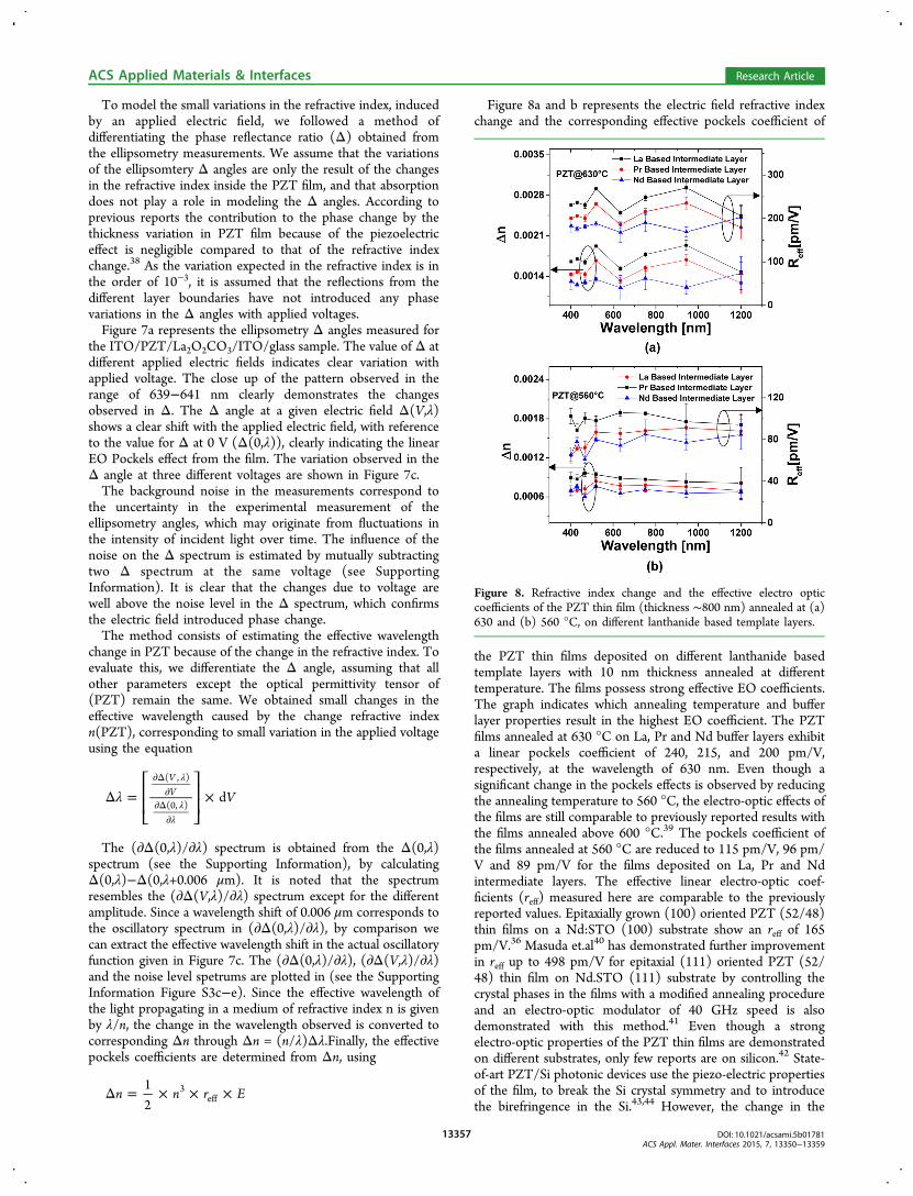
Figure 8a and b represents the electric field refractive indexchange and the corresponding effective pockels coefficient of
the PZT thin films deposited on different lanthanide basedtemplate layers with 10 nm thickness annealed at differenttemperature. The films possess strong effective EO coefficients.The graph indicates which annealing temperature and bufferlayer properties result in the highest EO coefficient. The PZTfilms annealed at 630 °C on La, Pr and Nd buffer layers exhibita linear pockels coefficient of 240, 215, and 200 pm/V,respectively, at the wavelength of 630 nm. Even though asignificant change in the pockels effects is observed by reducingthe annealing temperature to 560 °C, the electro-optic effects ofthe films are still comparable to previously reported results withthe films annealed above 600 °C.39 The pockels coefficient ofthe films annealed at 560 °C are reduced to 115 pm/V, 96 pm/V and 89 pm/V for the films deposited on La, Pr and Ndintermediate layers. The effective linear electro-optic coef-ficients (reff) measured here are comparable to the previouslyreported values. Epitaxially grown (100) oriented PZT (52/48)thin films on a Nd:STO (100) substrate show an reff of 165pm/V.36 Masuda et.al40 has demonstrated further improvementin reff up to 498 pm/V for epitaxial (111) oriented PZT (52/48) thin film on Nd.STO (111) substrate by controlling thecrystal phases in the films with a modified annealing procedureand an electro-optic modulator of 40 GHz speed is alsodemonstrated with this method.41 Even though a strongelectro-optic properties of the PZT thin films are demonstratedon different substrates, only few reports are on silicon.42 State-of-art PZT/Si photonic devices use the piezo-electric propertiesof the film, to break the Si crystal symmetry and to introducethe birefringence in the Si.43,44 However, the change in the
Figure 8. Refractive index change and the effective electro opticcoefficients of the PZT thin film (thickness ∼800 nm) annealed at (a)630 and (b) 560 °C, on different lanthanide based template layers.
ACS Applied Materials & Interfaces Research Article
refractive index observed in these devices are an order ofmagnitude smaller compared to the electro-optics effectsmeasured here.
■ CONCLUSIONIn conclusion, a novel strategy for fabricating highly texturedPZT thin films on silicon has been developed, by utilizing achemical solution deposition route. We have developed anumber of novel ultrathin lanthanide based intermediate layers,as template layers for textured thin film growth on differentsubstrates. The structural characterizations of the filmsdemonstrate strong preferential thin film growth, with wellpacked, crack free polygonal crystal grains. The PZT thin filmshave a strong columnar structure with a high degree oforientation (>99.8%) regardless of the thin film growthconditions. The dielectric constant measurement of the filmsshows the expected trend with a large dielectric constant ∼600(scaled by the buffer layer thickness, dielectric constant, andelectrode parameters). The hysteresis and leakage currentmeasurement shows low coercive field, strong remnantpolarization, and large breakdown voltage. Strong electro-optic properties of the as-deposited thin films (ranging from120 to 240 pm/V), estimated by the ellipsomtery technique,indicate that this PZT film is an ideal candidate for siliconnanophotonics EO modulators. The novel deposition methodoffers a low cost and simple method to produce good quality,strongly electro-optic PZT thin films on crystalline andamorphous (SiO2 and Si3N4) substrates for a variety ofintegrated photonics and electronics applications, where theproperties of the films can be tuned for applications spanningfrom microwave to the optical frequencies.
■ ASSOCIATED CONTENT*S Supporting InformationSome details of the X-ray diffraction measurements, polefigures, atomic force microscopy (AFM) measurements and thedetails of the electro-optic characterization of the PZT films.The Supporting Information is available free of charge on theACS Publications website at DOI: 10.1021/acsami.5b01781.
NotesThe authors declare no competing financial interest.
■ ACKNOWLEDGMENTSThis research was supported by the Interuniversity AttractionPoles program of the Belgian Science Policy Office, under grantIAP P7-35 (Photonics@be)
■ REFERENCES(1) Kobayashi, T.; Oyama, S.; Takahashi, M.; Maeda, R.; Itoh, T.Microelectromechanical Systems-Based Electrostatic Field SensorUsing Pb(Zr,Ti)O3 Thin Films. Jpn. J. Appl. Phys. 2008, 47, 7533.(2) Xiao, B.; Avrutin, V.; Liu, H. Y.; Ozgur, U.; Morkoc, H.; Lu, C. Z.Large Pyroelectric Effect in Undoped Epitaxial Pb(Zr,Ti)O3 ThinFilms on SrTiO3 Substrates. Appl. Phys. Lett. 2008, 93, No. 052913.(3) Lei, X. Y.; Remiens, D.; Sama, N.; Chen, Y.; Mao, C. L.; Dong, X.L.; Wang, G. S. Dielectric, Ferroelectric and Piezoelectric Properties of100-Oriented Pb0.4Sr0.6TiO3 Thin Film Sputtered on LaNiO3Electrode. J. Cryst. Growth 2012, 347, 15.
(4) Zhu, M. M.; Du, Z. H.; Ma, J. Influence of Crystal Phase andTransparent Substrates on Electro-Optic Properties of Lead ZirconateTitanate Films. J. Appl. Phys. 2010, 108, No. 113119.(5) Eom, C. B.; Trolier-McKinstry, S. Thin-Film PiezoelectricMEMS. MRS Bull. 2012, 37, 1007−1021.(6) Sriram, S.; Bhaskaran, M.; Holland, A. S.; Short, K. T.; Latella, B.A. Measurement of High Piezoelectric Response of Strontium-DopedLead Zirconate Titanate Thin Films Using a Nanoindenter. J. Appl.Phys. 2007, 101, No. 104910.(7) Bin, C.; Zhenghu, Z.; Yiwei, L.; Qing-Feng, Z.; Yali, X.; Huali, Y.;Guohong, D.; Zhixiang, L.; Gaojie, X.; Run-Wei, L. TunablePhotovoltaic Effects in Transparent Pb(Zr 0.53,Ti 0.47)O3 Capacitors.Appl. Phys. Lett. 2012, 100, No. 173903.(8) Luo, C.; Cao, G. Z.; Shen, I. Y. Development of a Lead-Zirconate-Titanate (PZT) Thin-Film Microactuator Probe for Intra-cochlear Applications. Sens. Actuators, A 2013, 201, 1−9.(9) Thapliya, R.; Okano, Y.; Nakamura, S. Electrooptic Character-istics of Thin-Film PLZT Waveguide Using Ridge-Type Mach-Zehnder Modulator. J. Lightwave Technol. 2003, 21, 1820−1827.(10) Xiong, C.; Pernice, W. H. P.; Ngai, J. H.; Reiner, J. W.; Kumah,D.; Walker, F. J.; Ahn, C. H.; Tang, H. X. Active Silicon IntegratedNanophotonics: Ferroelectric BaTiO3 Devices. Nano Lett. 2014, 14,1419−1425.(11) Kim, J.; Yang, S. A.; Choi, Y. C.; Han, J. K.; Jeong, K. O.; Yun, Y.J.; Kim, D. J.; Yang, S. M.; Yoon, D.; Cheong, H.; Chang, K. S.; Noh,T. W.; Bu, S. D. Ferroelectricity in Highly Ordered Arrays of Ultra-Thin-Walled Pb(Zr,Ti)O3 Nanotubes Composed of Nanometer-SizedPerovskite Crystallites. Nano Lett. 2008, 8, 1813−1818.(12) Datta, A.; Mukherjee, D.; Witanachchi, S.; Mukherjee, P.Hierarchically Ordered Nano-Heterostructured PZT Thin Films withEnhanced Ferroelectric Properties. Adv. Funct. Mater. 2014, 24, 2638−2647.(13) Chen, X.; Xu, S. Y.; Yao, N.; Shi, Y. 1.6 V Nanogenerator forMechanical Energy Harvesting Using PZT Nanofibers. Nano Lett.2010, 10, 2133−2137.(14) Datta, A.; Mukherjee, D.; Hordagoda, M.; Witanachchi, S.;Mukherjee, P.; Kashid, R. V.; More, M. A.; Joag, D. S.; Chavan, P. G.Controlled Ti Seed Layer Assisted Growth and Field EmissionProperties of Pb(Zr0.52Ti0.48)O3 Nanowire Arrays. ACS Appl. Mater.Interfaces 2013, 5, 6261−6267.(15) Tang, P. S.; Towner, D. J.; Hamano, T.; Meier, A. L.; Wessels, B.W. Electrooptic Modulation up to 40 GHz in a Barium Titanate ThinFilm Waveguide Modulator. Opt. Express 2004, 12, 5962−5967.(16) Wooten, E. L.; Kissa, K. M.; Yi-Yan, A.; Murphy, E. J.; Lafaw, D.A.; Hallemeier, P. F.; Maack, D.; Attanasio, D. V.; Fritz, D. J.; McBrien,G. J.; Bossi, D. E. A Review of Lithium Niobate Modulators for Fiber-Optic Communications Systems. IEEE J. Sel. Top. Quantum Electron.2000, 6, 69−82.(17) Rabiei, P.; Ma, J. C.; Khan, S.; Chiles, J.; Fathpour, S.Heterogeneous Lithium Niobate Photonics on Silicon Substrates. Opt.Express 2013, 21, 25573−25581.(18) Masuda, S.; Seki, A.; Shiota, K.; Masuda, Y. Mach-ZehnderInterferometer-Type Photonic Switches Based on Epitaxially GrownLanthanum-Modified Lead Zirconate Titanate Films. J. LightwaveTechnol. 2011, 29, 209−214.(19) Abel, S.; Stoeferle, T.; Marchiori, C.; Rossel, C.; Rossell, M. D.;Erni, R.; Caimi, D.; Sousa, M.; Chelnokov, A.; Offrein, B. J.;Fompeyrine, J. A Strong Electro-Optically Active Lead-Free Ferro-electric Integrated on Silicon. Nat. Commun. 2014, 4, 1−6.(20) Cooney, T. G.; Francis, L. F. Processing of Sol−Gel DerivedPZT Coatings on Non-Planar Substrates. J. Micromech. Microeng. 1996,6, 291−300.(21) Frunza, R.; Ricinschi, D.; Gheorghiu, F.; Apetrei, R.; Luca, D.;Mitoseriu, L.; Okuyama, M. Preparation and Characterisation of PZTFilms by RF-Magnetron Sputtering. J. Alloy. Compd. 2011, 509, 6242−6246.(22) Menou, N.; Funakubo, H. (111)-Oriented Pb(Zr,Ti)O3 FilmsDeposited on SrRuO3/Pt Electrodes: Reproducible Preparation by
ACS Applied Materials & Interfaces Research Article
Metal Organic Chemical Vapor Deposition, Top Electrode Influence,and Reliability. J. Appl. Phys. 2007, 102, No. 114105.(23) Borowiak, A. S.; Niu, G.; Pillard, V.; Agnus, G.; Lecoeur, P.;Albertini, D.; Baboux, N.; Gautier, B.; Vilquin, B. Pulsed LaserDeposition of Epitaxial Ferroelectric Pb(Zr,Ti)O3 Films on SiliconSubstrates. Thin Solid Films 2012, 520, 4604−4607.(24) Lin, Y.; Zhao, B. R.; Peng, H. B.; Xu, B.; Chen, H.; Wu, F.; Tao,H. J.; Zhao, Z. X.; Chen, J. S. Growth and Polarization Features ofHighly (100) Oriented Pb(Zr0.53Ti0.47)O3 Films on Si with UltrathinSiO2 Buffer Layer. Appl. Phys. Lett. 1998, 73, 2781−2783.(25) Chen, L.; Shen, M. R.; Fang, L.; Xu, Y. Microstructure Controlof (Pb,Sr)TiO3 Films on Pt/Ti/SiO2/Si Substrates by a TiO2 BufferLayer. Thin Solid Films 2008, 516, 1285−1289.(26) Yu, J.; Meng, X. J.; Sun, J. L.; Huang, Z. M.; Chu, J. H. Opticaland Electrical Properties of Highly (100)-Oriented PbZr1−xTixO3 ThinFilms on the LaNiO3 Buffer Layer. J. Appl. Phys. 2004, 96, 2792−2799.(27) Shih, W. C.; Yen, Z. Z.; Liang, Y. S. Preparation of Highly c-Axis-Oriented PZT Films on Si Substrate with Mgo Buffer Layer bythe Sol−Gel Method. J. Phys. Chem. Solids 2008, 69, 593−596.(28) Chen, L.; Reano, R. M. Compact Electric Field Sensors Basedon Indirect Bonding of Lithium Niobate to Silicon Microrings. Opt.Express 2012, 20, 4032−4038.(29) Kim, D. M.; Eom, C. B.; Nagarajan, V.; Ouyang, J.; Ramesh, R.;Vaithyanathan, V.; Schlom, D. G. Thickness Dependence of Structuraland Piezoelectric Properties of Epitaxial Pb(Zr0.52Ti0.48)O3 Films on Siand SrTiO3 Substrates. Appl. Phys. Lett. 2006, 88, No. 142904.(30) Balboul, B. A. A.; Myhoub, A. Y. Z. The Characterization of theFormation Course of Neodymium Oxide from Different Precursors: AStudy of Thermal Decomposition and Combustion Processes. J. Anal.Appl. Pyrolysis 2010, 89, 95−101.(31) Klingenberg, B.; Vannice, M. A. Influence of Pretreatment onLanthanum Nitrate, Carbonate, and Oxide Powders. Chem. Mater.1996, 8, 2755−2768.(32) Shirsat, A. N.; Ali, M.; Kaimal, K. N. G.; Bharadwaj, S. R.; Das,D. Thermochemistry of La2O2CO3 Decomposition. Thermochim. Acta2003, 399, 167−170.(33) Olafsen, A.; Fjellvag, H. Synthesis of Rare Earth OxideCarbonates and Thermal Stability of Nd2O2CO3ii. J. Mater. Chem.1999, 9, 2697−2702.(34) Lefevre, M. J.; Speck, J. S.; Schwartz, R. W.; Dimos, D.;Lockwood, S. J. Microstructural Development in Sol−Gel DerivedLead Zirconate Titanate Thin Films: The Role of PrecursorStoichiometry and Processing Environment. J. Mater. Res. 1996, 11,2076−2084.(35) Wang, Y.; Ganpule, C.; Liu, B. T.; Li, H.; Mori, K.; Hill, B.;Wuttig, M.; Ramesh, R.; Finder, J.; Yu, Z.; Droopad, R.; Eisenbeiser, K.Epitaxial Ferroelectric Pb(Zr,Ti)O3 Thin Films on Si Using SrTiO3Template Layers. Appl. Phys. Lett. 2002, 80, 97−99.(36) Kang, T. D.; Xiao, B.; Avrutin, V.; Ozgur, U.; Morkoc, H.; Park,J. W.; Lee, H. S.; Lee, H.; Wang, X. Y.; Smith, D. J. Large Electro-OpticEffect in Single-Crystal Pb(Zr,Ti)O3 (001) Measured by SpectroscopicEllipsometry. J. Appl. Phys. 2008, 104, No. 093103.(37) Akazawa, H.; Shimada, M. Spectroellipsometric Approach toDetermine Linear Electro-Optic Coefficient of C-Axis-OrientedLiNbO3 Thin Films. J. Appl. Phys. 2005, 98, No. 113501.(38) Spirin, V. V.; Lee, C. H.; No, K. S. Measurement of the PockelsCoefficient of Lead Zirconate Titanate Thin Films by a Two-BeamPolarization Interferometer with a Reflection Configuration. J. Opt.Soc. Am. B 1998, 15, 1940−1946.(39) Lee, C.; Spirin, V.; Song, H.; No, K. Drying Temperature Effectson Microstructure, Electrical Properties and Electro-Optic Coefficientsof Sol−Gel Derived PZT Thin Films. Thin Solid Films 1999, 340,242−249.(40) Masuda, S.; Seki, A.; Masuda, Y. Influence of Crystal Phases onElectro-Optic Properties of Epitaxially Grown Lanthanum-ModifiedLead Zirconate Titanate Films. Appl. Phys. Lett. 2010, 96, No. 072901.(41) Masuda, S.; Seki, A.; Shiota, K.; Hara, H.; Masuda, Y. Electro-Optic and Dielectric Characterization of Ferroelectric Films for High-
Speed Optical Waveguide Modulators. J. Appl. Phys. 2011, 109,No. 124108.(42) Kurihara, K.; Kondo, M.; Sato, K.; Ishii, M.; Wakiya, N.;Shinozaki, K. Electrooptic Properties of Epitaxial Lead ZirconateTitanate Films on Silicon Substrates. Jpn. J. Appl. Phys., Part 1 2007,46, 6929−6932.(43) Sebbag, Y.; Goykhman, I.; Desiatov, B.; Nachmias, T.; Yoshaei,O.; Kabla, M.; Meltzer, S. E.; Levy, U. Bistability in Silicon MicroringResonator Based on Strain Induced by a Piezoelectric Lead ZirconateTitanate Thin Film. Appl. Phys. Lett. 2012, 100, No. 141107.(44) Tsia, K. K.; Fathpour, S.; Jalalia, B. Electrical Tuning ofBirefringence in Silicon Waveguides. Appl. Phys. Lett. 2008, 92,No. 061109.
ACS Applied Materials & Interfaces Research Article