Large Generator Interconnection System Impact Study Report Qualifying Facility Completed for LGIQ#Q0460 Proposed Interconnection 230 kV Gonder - Pavant Transmission Line at or near Pole # 554 July 24, 2013
Transcript
Large Generator Interconnection System Impact Study Report
Qualifying Facility
Completed for LGIQ#Q0460
Proposed Interconnection 230 kV Gonder - Pavant Transmission Line
at or near Pole # 554
July 24, 2013
System Impact Study Report
Page i July 24, 2013 Q0460
TABLE OF CONTENTS 1.0 DESCRIPTION OF THE GENERATING FACILITY .................................................................... 1 2.0 SCOPE OF THE STUDY ................................................................................................................. 1 3.0 TYPE OF INTERCONNECTION SERVICE .................................................................................. 2 4.0 DESCRIPTION OF PROPOSED INTERCONNECTION ............................................................... 2
4.1 Other Options Considered (NERC Requirement) ...................................................................... 2 5.0 STUDY ASSUMPTIONS ................................................................................................................. 2
6.0 PARTICIPATION BY AFFECTED SYSTEMS ............................................................................ 21 7.0 APPENDIX 1: PROPERTY REQUIREMENTS ............................................................................ 22 8.0 APPENDIX 2 – COMBINED QUEUE EAST ............................................................................... 24
System Impact Study Report
Page 1 July 24, 2013 Q0460
1.0 DESCRIPTION OF THE GENERATING FACILITY
“Interconnection Customer” proposed interconnecting 159.80 MW of new generation to PacifiCorp’s (“Transmission Provider”) transmission system to the 230 kV Gonder - Pavant transmission line at or near pole # 554 located in Millard County, Utah. The project (“Project”) will consist of ninety four (94) GE 1.7 MW WTG’s for a total Project output of 159.80 MW. The requested commercial operation date is approximately December 31, 2015. Interconnection Customer will operate this generator as a Qualified Facility as defined by the Public Utility Regulatory Policies Act of 1978 (PURPA). Transmission Provider has assigned the Project Queue “Q0460.”
2.0 SCOPE OF THE STUDY
The interconnection system impact study shall evaluate the impact of the proposed interconnection on the reliability of the transmission system. The interconnection system impact study will consider Base Case as well as all generating facilities (and with respect to (iii) below, an identified network upgrades associated with such higher queued interconnection) that, on the date the interconnection system impact study is commenced:
(i) are directly interconnected to the transmission system; (ii) are interconnected to Affected Systems and may have an impact on the interconnection
request; (iii) have a pending higher queued interconnection request to interconnect to the
transmission system; and (iv) have no Queue Position but have executed an LGIA or requested that an unexecuted
LGIA be filed with FERC. The interconnection system impact study will consist of a short circuit analysis, a stability analysis, and a power flow analysis. The interconnection system impact study will state the assumptions upon which it is based; state the results of the analyses; and provide the requirements or potential impediments to providing the requested interconnection service, including preliminary indication of the cost and length of time that would be necessary to correct any problems identified in those analyses and implement the interconnection. The interconnection system impact study will provide a list of facilities that are required as a result of the Interconnection Request and a non-binding good faith estimate of the cost responsibility and a non-binding good faith estimated time to construct.
System Impact Study Report
Page 2 July 24, 2013 Q0460
3.0 TYPE OF INTERCONNECTION SERVICE
The Interconnection Customer has selected Qualified Facility (QF) interconnection service.
4.0 DESCRIPTION OF PROPOSED INTERCONNECTION
The Q0460 Project has proposed to connect to the Transmission Provider’s existing 230kV Gonder – Pavant transmission line. When the Transmission Provider’s new Black Rock Substation is operational, this transmission line segment will be renamed to the 230 kV Black Rock – Osceola transmission line. To interconnect the Q0460 Project to the Transmission Providers existing transmission system will require the construction of a new 230 kV three breaker ring bus point of interconnection substation and looping in the existing 230 kV Gonder - Pavant transmission line. The point of interconnection substation will include a control house, Project metering, communication and protection and control equipment.
4.1 Other Options Considered (NERC Requirement)
The Interconnection Customer could have chosen to interconnect the Q0460 Project to the new Black Rock Substation. An interconnection to the Black Rock Substation was not chosen by the Interconnection Customer because of a concern about acquiring property rights to site and build a radial transmission line to the Black Rock Substation.
5.0 STUDY ASSUMPTIONS
All active higher priority transmission service and/or generator interconnection requests will be considered in this study and are listed in Appendix 1. If any of these requests are withdrawn, the Transmission Provider reserves the right to re-evaluate this request, and the results and conclusions could significantly change.
For study purposes there are two separate queues:
o Transmission Service Queue: to the extent practical, all network upgrades that are required to accommodate active transmission service requests and are expected to be in-service on or after the Interconnection Customer’s requested in-service date for the Project will be modeled in this study.
o Generation Interconnection Queue: when relevant, interconnection facilities associated with higher queue interconnection requests will be modeled in this study. However, network upgrades required to provide delivery will only be modeled for projects which have requested network resource integration service only. No generation will be simulated from any higher queued project unless a commitment has been made to obtain transmission service.
System Impact Study Report
Page 3 July 24, 2013 Q0460
The Interconnection Customer’s request for energy or network resource interconnection service in and of itself does not convey transmission service. Only a Network Customer can make a request to designate a generating resource as a network resource. Since the queue of higher priority transmission services requests may be different when and if a Network Customer’s requests network resource designation for this generation facility, the available capacity or transmission modifications, if any, necessary to provide network resource interconnection service may be significantly different. Therefore, the Interconnection Customer should regard the results of this study as informational rather than final.
Under normal conditions, the Transmission Provider does not dispatch or otherwise directly control or regulate the output of generation facilities. Therefore, the need for transmission modifications, if any, which are required to provide network resource interconnection service will be evaluated on the basis of 100 percent deliverability (i.e., no displacement of other resources in the same area). However, a network customer can elect to designate more generating resources in an area than can be accommodated by existing or planned transmission capacity. The network customer would then be required to dispatch the resources so as to limit total generation so as not to exceed the network customer’s transmission rights.
This study assumes the Project will be integrated into the Transmission Provider’s system on the 230 kV Black Rock – Osceola transmission line at or near pole # 554.
The Interconnection Customer will construct and own any facilities required between
the point of interconnection and the Project.
Generator tripping may be required for certain outages. All facilities will meet or exceed the minimum WECC, NERC, and the Transmission
Provider’s performance and design standards.
If wind turbines are connected electrically near series capacitors, then specialized studies to consider SSR (Sub-Synchronous Resonance) and Sub-Synchronous Control Interactions (SSCI) may be required. If N-1 or N-2 contingencies results in a radial path of the turbines into the series capacitors, then studies are essential – for other non-radial configurations, the studies are necessary at the discretion of the Transmission Provider. Such studies must demonstrate that the wind turbine controls do not contribute negative damping to the system, and that the mechanical modes of resonance in the turbine do not interact with system series capacitors. If such interactions occur, it is the responsibility of the wind developer to provide remedies, and to provide adequate protection to ensure the sub-synchronous interactions are detected and the wind turbines tripped.
System Impact Study Report
Page 4 July 24, 2013 Q0460
The Transmission Provider allows post contingency voltage limits of 0.9 per unit (pu) and 1.1 pu.
Q0460 wind generating project was modeled holding voltage of 1.035 pu (238.05 kV) at the point of interconnection.
The generation step up transformer’s high side voltage winding was modeled with the high side tap at +2.5% or 235.75 kV.
Total west and east bound transmission capacity on the WECC Path 32 is limited to 330 MW and 235 MW respectively.
Total imports into Nevada Energy’s Gonder 230 kV bus from Utah (including Spring Valley generation, which is located on the west side of the Utah-Nevada state line on the Pavant - Gonder 230 kV line) are limited to 440 MW.
The switch between the two Delta 46 kV north taps will be operated normally open and the switch between Sutherland and Intermountain Power Project north 46 kV tap will be required to be operated normally open.
58 MW and 20 MW (does not include losses) of loads were assumed between Black Rock and Pavant for heavy load situations and light load conditions, respectively. Peak load served out of Black Rock and Pavant recorded for 2012 was 49.5 MW (included losses).
This report is based on information available at the time of the study (July 24, 2013). It is the Interconnection Customer’s responsibility to check the Transmission Provider’s web site regularly for Transmission system updates at http://www.pacificorp.com/tran.html.
System Impact Study Report
Page 5 July 24, 2013 Q0460
5.1 Qualified Facility (QF) Interconnection Service
Delivery through QF interconnection service allows the Interconnection Customer to integrate its large generating facility with the Transmission Provider’s transmission system in a manner comparable to that in which the Transmission Provider integrates its generating facilities to serve native load customers. The transmission system is studied at peak load, under a variety of severely stressed conditions. In order to determine the transmission modifications, if any, which are necessary in order to deliver the aggregate generation in the area of the point of interconnection to the Transmission Provider’s aggregate load, and assumes that no portion of existing network resources are displaced by the output of the Interconnection Customer’s generating facility. The physical interconnection study process does not evaluate any transmission system upgrades required to move the generation across the transmission system nor does it convey or reserve transmission service. Only a Network Customer can request Transmission Service for a Qualifying Facility and details of the transmission system improvements required to deliver 100% of the Projects generation to the Transmission Provider’s Network Load can only be determined through the separate Transmission Service Request study process.
5.1.1 Study Results
The PSS/E version 32 program was used to evaluate the steady state performance of the system for each of the contingencies described in Table 1. The 2017 Heavy Summer WECC case (17hs1ap.sav) was used for this analysis. The study area was limited to Central Utah. Since the point of interconnection is located on the Gonder to Pavant 230 kV line, which is part of WECC Path 32, the case was tuned to meet the maximum obligation on the WECC Path 32. The WECC Path 32 is comprised of two 230 kV lines; one line from Gonder to Pavant and another line from Gonder to Intermountain Power Project (IPP).
Table 1: List of Contingencies Number Contingency
1 Black Rock to Pavant 230 kV line outage
2 Black Rock to POI (Q0460) 230 kV line outage
3 Osceola to POI (Q0460) 230 kV line outage
4 Gonder to Osceola 230 kV line outage
5 Gonder to Intermountain Power Project (IPP) 230 kV line outage
6 Pavant to Sigurd 230 kV line outage
System Impact Study Report
Page 6 July 24, 2013 Q0460
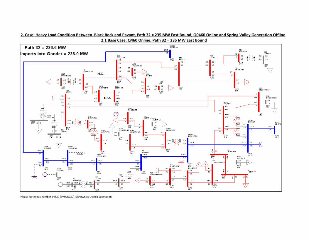
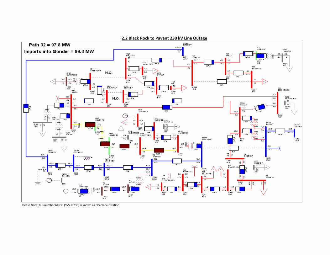
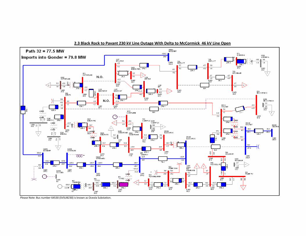
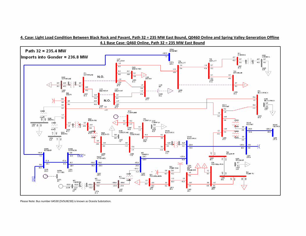
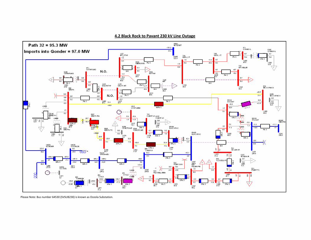
Different cases considering the maximum obligation on the WECC Path 32 (east- and westbound) with heavy and light load conditions between Pavant and Black Rock substations were studied. Spring Valley generation was also considered during the analysis. Prior to the addition of Q0460, no thermal and voltage violations are observed on the lower voltage system between Black Rock and Pavant substations for an outage of Black Rock to Pavant 230 kV line. For heavy load conditions between Black Rock and Pavant, with 235 MW of eastbound flow on the WECC Path 32, Spring Valley generation on line and Q0460 in service at its maximum generation capability, the outage of Black Rock to Pavant 230 kV line causes the Black Rock to Delta 69 kV line to overload to 136 % of its emergency rating. The Delta 69/46 kV transformer and Delta 46 kV voltage regulating transformer overload to 131 % and 151 % of their emergency ratings, respectively. Low voltages of 0.88 pu, 0.89 pu and 0.89 pu are observed at Delta 69 kV, Delta 46 kV and Lyndyl 46 kV bus. For heavy load conditions between Black Rock and Pavant, with 235 MW eastbound flow on the WECC Path 32, Spring Valley generation off line and Q0460 in service at its maximum generation capability, the outage of the Black Rock to Pavant 230 kV line causes the Black Rock to Delta 69 kV line to overload to 134 % of its emergency rating. The Delta 69/46 kV transformer and Delta 46 kV voltage regulating transformer overload to 130 % and 149 % of their emergency rating, respectively. Low voltages of 0.88 pu, 0.89 pu and 0.89 pu are observed at Delta 69 kV, Delta 46 kV and Lyndyl 46 kV bus. For light load conditions between Black Rock and Pavant and, with 235 MW of eastbound flow on the WECC Path 32, Spring Valley generation on line and Q0460 in service at its maximum generation capability, the outage of the Black Rock to Pavant 230 kV line causes the Black Rock to Delta 69 kV line to overload to 116 % of its emergency rating. The Delta 69/46 kV transformer and Delta 46 kV voltage regulating transformer overload to 100 % and 118 % of their emergency rating, respectively and the 46 kV line from Delta to McCormick overloads to 105% of its emergency rating. For light load conditions between Black Rock and Pavant, with 235 MW of eastbound flow on the WECC Path 32, Spring Valley generation off line and Q0460 in service at its maximum generation capability, the outage of the Black Rock to Pavant 230 kV line causes the Black Rock to Delta 69 kV line to overload to 115 % of its emergency rating. The Delta 69/46 kV transformer and Delta 46 kV voltage regulating transformer overload to 102 % and 122 % of their emergency rating, respectively and the 46 kV line from Delta to McCormick overloads to 105 % of its emergency rating. The voltage and thermal overload violations observed on the 69 kV and 46 kV transmission line system between Black Rock and Pavant for an outage of the Black Rock to Pavant 230 kV line can be mitigated by installing a tripping scheme to trip the Delta to McCormick 46 kV line if the Delta 69/46 kV transformer or Delta 46 kV voltage regulating transformer exceed their emergency rating.
System Impact Study Report
Page 7 July 24, 2013 Q0460
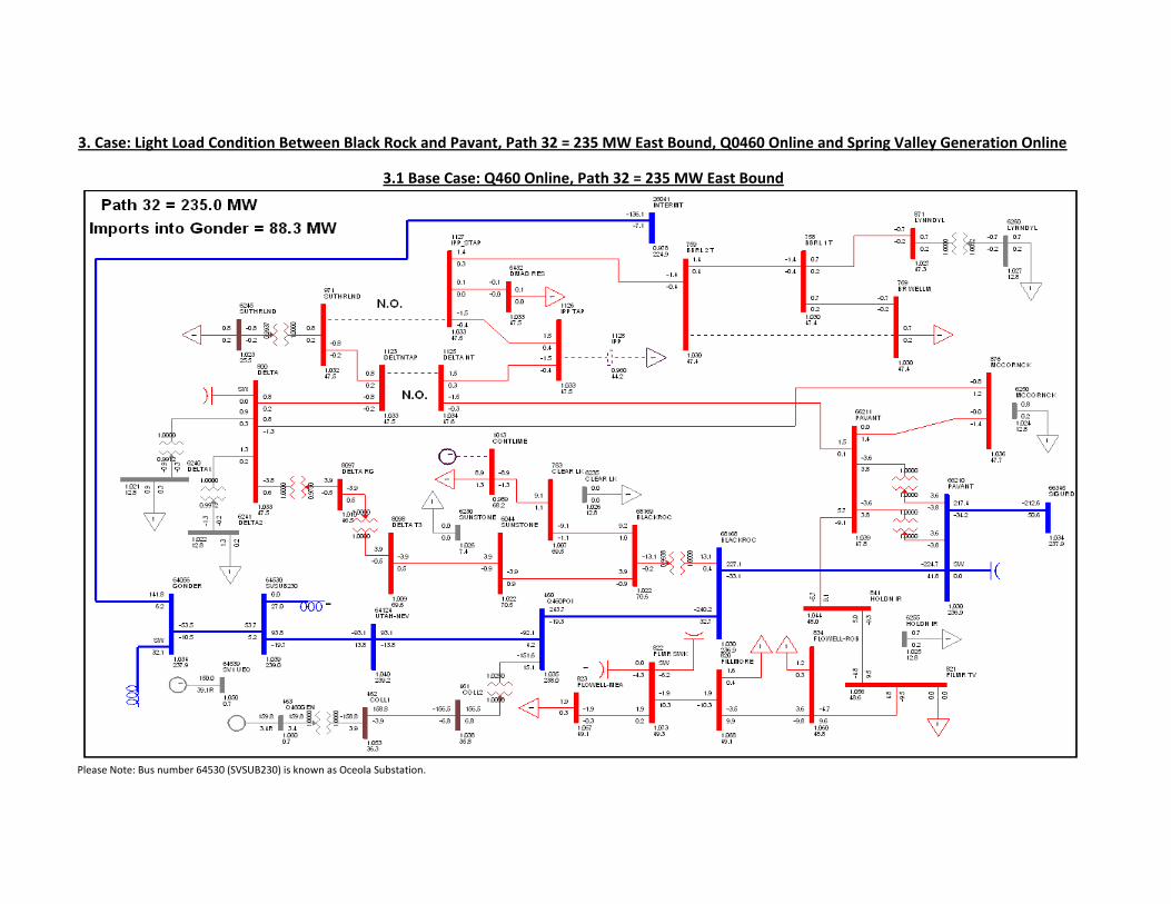
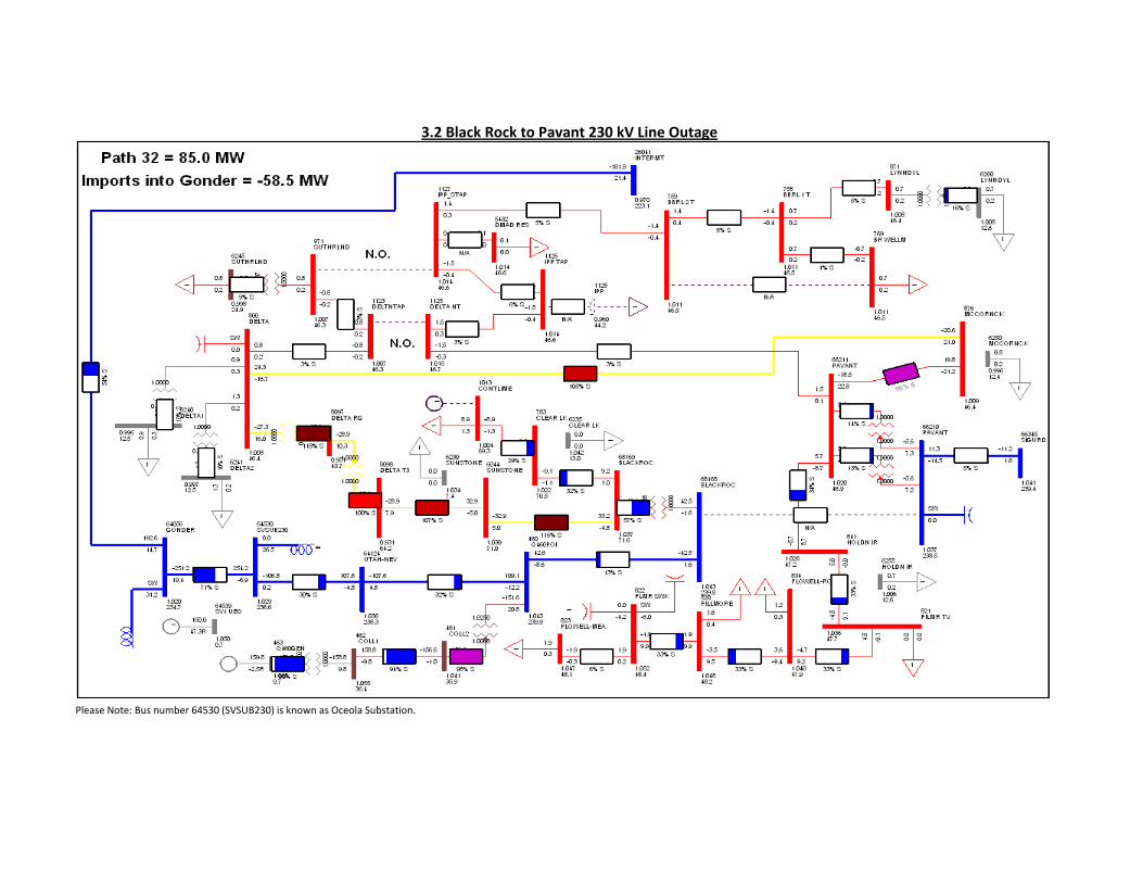
For a heavy load condition between Black Rock and Pavant, with 330 MW of westbound flow on the WECC Path 32, Spring Valley generation on line and Q0460 in service with its maximum generation capability, low voltage of 0.89 pu was observed at Lyndyl 46 kV bus for an outage of the Black Rock to Pavant 230 kV line, low voltage of 0.89 pu was observed at Lyndyl 46 kV bus for an outage of the Gonder to Osceola 230 kV line. For a heavy load conditions between Black Rock and Pavant, with 330 MW of westbound flow on the WECC Path 32, Spring Valley generation off line and Q0460 in service with its maximum generation capability, outage of the Black Rock to Pavant line caused low voltage of 0.89 pu at Lyndyl 46 kV bus. These low voltages observed on the 46 kV system between Black Rock and Pavant are marginally acceptable. At present (Q0460 not interconnected), for light load conditions between Black Rock and Pavant, with 235 MW of eastbound flow on the WECC Path 32 and Spring Valley generation online, the Pavant to Sigurd 230 kV line outage causes voltage of 1.083 pu at the Black Rock and Pavant 230 kV buses. With Q0460 wind turbines operated offline, post contingency of Pavant to Sigurd 230 kV line, the wind farm collector system supplies approximately 15 MVAr of reactive charging in to the point of interconnection which causes over voltage (above 1.1 pu) at Black Rock and Pavant 230 kV buses and the 46 kV buses served out of Pavant. These voltage violations can be mitigated by installing Wind Free Technology on the GE wind turbines or by installing a shunt reactor at the point of interconnection. Preliminary study shows that a 15 MVAr shunt reactor at the point of interconnection (230 kV) will be required. Table 2 shows the post Pavant to Sigurd 230 kV line outage voltages recorded pre and post 15 MVAr shunt reactor at Point of Interconnection (230 kV) at Black Rock, Pavant and Point of Interconnection 230 kV buses and 69 kV Pavant bus. Power flow plots showing study results are shown in Appendix 3 which is attached to the report. Table 2: Change in Voltage Due to 15 MVAr Shunt Reactor at the Point of Interconnection (POI)
Post Pavant to Sigurd 230 kV Line Outage With Q0460 Offline:
Substation Voltage Without 15 MVAr
at POI (pu) Voltage With 15 MVAr
at POI (pu) Change in
Voltage (%) POI 230 kV Bus 1.107 1.075 3.2 Black Rock 230 kV Bus
1.109 1.077 3.2
Pavant 230 kV Bus
1.109 1.077 3.2
Pavant 69 kV Bus
1.106 1.074 3.2
System Impact Study Report
Page 8 July 24, 2013 Q0460
5.1.2 Requirements
5.1.2.1 Generating Facility Modifications
The Generation and Interconnection facilities owned by the Interconnection Customer are required to operate under automatic voltage control with the voltage sensed electrically at the point of interconnection. The generating and interconnecting facility should have sufficient reactive capacity to enable the delivery of 100 percent of the plant output to the point of interconnection at unity power factor measured at 1.0 per unit voltage under steady state conditions. Generators capable of operating under voltage control with a voltage droop are required to do so. Studies will be required to coordinate the voltage droop setting with other facilities in the area. As required by NERC standard VAR-001-1a, the Transmission Provider will provide a voltage schedule for the Point of Interconnection. When voltage droop controls are not available, the generation and interconnection facilities should be operated so as to maintain the voltage at the point of interconnection between 1.01 pu to 1.04 pu. At the Transmission Provider’s discretion, these values might be adjusted depending on the operating conditions. Within this voltage range, the generating and interconnecting facilities should operate so as to minimize the reactive interchange between the generation/interconnection facilities and the Transmission Provider’s system (operation fixed at unity power factor at the point of interconnection). If the voltage is outside the upper or lower range, the voltage control scheme should operate so as to utilize the reactive capabilities of the generating and interconnecting facilities to maintain the voltage to a value within the control band. The voltage control settings of the generation and interconnection facilities must be coordinated with the Transmission Provider prior to energization (or interconnection). The reactive compensation must be designed such that the reactive switching (if required by the Interconnection Customer) does not cause step voltage changes greater than +/-3% on the Transmission Provider’s system. If wind turbines are connected electrically near series capacitors, then specialized studies to consider SSR (Sub-Synchronous Resonance) and Sub-Synchronous Control Interactions (SSCI) may be required. If N-1 or N-2 contingencies result in a radial path of the turbines into the series capacitors, SSR and SSCI studies would be required; for other non-radial configurations, the studies are necessary at the discretion of the Transmission Provider. Such studies must demonstrate that the wind turbine controls do not contribute negative damping to the system, and that the mechanical modes of resonance in the turbine do not interact with system series capacitors. If such interactions occur, it is the responsibility of the wind developer to provide remedies, and to provide adequate protection to ensure the sub-synchronous interactions are detected and the wind turbines tripped.
System Impact Study Report
Page 9 July 24, 2013 Q0460
If wind turbines are offline (no wind), the wind farm collector system generates reactive charging which can cause overvoltage at the point of interconnection and neighboring substations post N-1 contingency. Generators capable of providing voltage control under zero wind conditions are required to do so. If voltage control, under conditions with low or no real power generation is unavailable, an appropriate size shunt reactor at the point of interconnection is needed to fully off-set the charging current.
System Impact Study Report
Page 10 July 24, 2013 Q0460
Figure 1: System one line diagram
System Impact Study Report
Page 11 July 24, 2013 Q0460
5.1.2.2 Existing Circuit Breaker Upgrades – Short Circuit
A short-circuit study was carried out using the Transmission Provider system model and the information provided by the Interconnection Customer. The results indicate that the new interconnection will not cause violations on the existing interrupting capacity of the circuit breakers at the Osceola or the Black Rock substations. For the new installations, it is recommended to specify at least the same interrupting capacity used for the circuit breakers at Black Rock, which is 40kA at 230kV.
5.1.2.3 Protection Requirements
As indicated in the one-line diagram shown in Figure 2, the proposed point of interconnection near pole 554 of the 230 kV line between the Black Rock and Osceola substations requires a new 230kV substation with three (3) circuit breakers. Currently, Black Rock is in the Rocky Mountain Power territory and Osceola is in the NV Energy territory. The new substation will function with a ring bus scheme; nevertheless, the design will allow developing it as a breaker-and-a-half substation in the future. As the Interconnection Customer assures the Q0460 230/34.5kV collector substation will be adjacent to pole 554, the connection between the new substation and the interconnection will be through a very short distance line. The Transmission Provider’s Q0460 point of interconnection substation will have all the protective gear specified by the Transmission Provider current standards. The lines to Osceola and Black Rock will have redundant pilot protection using distance relays (POTTD) and an appropriate communication system compatible with the existing microwave system at the Black Rock and Osceola substations. This communication system will also serve to connect the SCADA master. Except for changes in the settings of the existing line relays, there will not be modifications to the protection equipment of the Osceola and Black Rock substations. It is expected that both the Transmission Provider’s Q0460 point of interconnection substation and the Interconnection Customer’s Q0460 collector substation will be connected to the same grounding grid; therefore, the short line segment between the Transmission Provider’s new substation and the 230kV circuit breaker in the Interconnection Customer substation will be protected with very fast high impedance differential protection using KAB relays. As a consequence, the current transformers between the circuit 230kV breaker and the transformer are necessary to connect the differential relays (See Figure 2). These current transformers may be in the bushing of the circuit breaker or in the 230kV bushing of the transformer. The CTs must have a 600T (3000/5) maximum turns ratio and a minimum C400 accuracy class. Solutions with auxiliary transformers are not accepted by the Transmission Provider standards. The bus differential relays will operate over a high-speed lockout relay which will trip the two 230kV breakers of the new Transmission Provider substation and the 230kV breaker of the Interconnection Customer.
System Impact Study Report
Page 12 July 24, 2013 Q0460
The Interconnection Customer will install in the Q0460 collector substation control house, a multifunction device with time phase and ground directional overcurrent elements which will serve as remote back-up of the line and bus differential protection (SEL351, for example). These overcurrent elements must be time-coordinated with all of the 230kV line relay elements. The same multifunction device can also be used as the monitor the voltage and frequency at the point of interconnection according to the Transmission Provider’s standard specifications. Any operation of this device by back-up overcurrent, overvoltage, undervoltage, underfrequency or overfrequency must trip the 230kV circuit breaker at the Interconnection Customer’s collector substation and the two corresponding 230kV circuit breakers at the Transmission Provider new Q0460 point of interconnection substation.
System Impact Study Report
Page 13 July 24, 2013 Q0460
Figure 2: One Line Diagram Showing Necessary CTs
System Impact Study Report
Page 14 July 24, 2013 Q0460
5.1.2.4 Data (RTU) Requirements
Data for the operation of the power system will be needed from the collector station Q0460. This data can be acquired by installing an RTU at the collector station if hardwired signals are to be provided or from an RS-232 DNP 3.0 serial connection if the customer provides a data collection device. In addition to the control and indication of the 230 kV breakers in Q0460 point of interconnection substation the following data will be acquired through the Q460 point of interconnection substation RTU. Also listed is the data that will be acquired from the Q0460 collector station. From Q0460 point of interconnection substation:
Analogs: Net Generation MW Net Generator MVAR
Accumulator Pulses: Interchange metering kWH
From the Q0460 collector substation:
Analogs: Real power flow through each of the 34.5 kV line feeder breakers Reactive power flow through each of the 34.5 kV line feeder breakers Reactive power flow from each of the shunt capacitor banks A phase 230 kV transmission voltage B phase 230 kV transmission voltage C phase 230 kV transmission voltage Wind speed Individual turbine Generation (in MW) Individual turbine Wind speed (m/sec) Individual turbine Wind direction (Azimuth Degrees) Individual turbine Wind Atmospheric Pressure (Bar) Individual turbine Temperature (Celsius) Individual turbine Availability Total Wind Farm Generation (MW) Average Wind Farm Wind Speed (m/s) Average Wind Farm Atmospheric Pressure (Bar) Average Wind Farm Temperature (Celsius) Total Wind Farm Available Capacity (MW)
Status: All 34.5 kV breakers Line Relay Alarm
System Impact Study Report
Page 15 July 24, 2013 Q0460
The interchange real power MW data will need to be transmitted from the backup meter to the Transmission Provider’s alternate energy control center at SCC/PCC independent of the MW supplied from the primary meter.
5.1.2.5 Substation Requirements
Design and build a new 230kV switching substation to allow for the connection of the Q0460 Project to the Black Rock – Osceola 230kV transmission line. To allow for the looping in and out of the 230kV line, the new 230kV switching substation is to be initially built as a three (3) breaker ring bus, but is to be designed and laid out with space provided for the ultimate substation expansion to a six (6) breaker ring. The entire point of interconnection substation is to be fenced. A list of the major equipment identified for this project is as follows:
3 – 242kV, 3000A, 40kA circuit breakers 10 – 230kV, 3000A, TPST, vertical break, manually operated switch ( 2 of these will
be used to isolate the metering CT/PTs) 2 – 230kV, 3000A, TPST, vertical break, manually operated switch equipped with
operated switch (used to by-pass the revenue meter facility) 6 – 144kV MCOV surge arresters 1 – 125 Volt, 100AH battery system with seismic zone 4 rated rack 1 – 16 Amp, 130Volt D/C, 120/208/240 volt A/C battery charger 6 – 230kV CCVT 1 – 230kV SSVT 1 – A/C auto throw-over switch 1 – 28’ x 40’ Transmission Provider standard control building
System Impact Study Report
Page 16 July 24, 2013 Q0460
5.1.2.6 Communication Requirements
A 48-strand, single mode, OPGW fiber cable is to be installed on the line between the Q0460 point of interconnection substation and the Black Rock Substation by the Transmission Provider on the Black Rock – Osceola line.
The Transmission Provider will supply and install fiber nodes and multiplex equipment in the Q0460 point of interconnection substation and the Black Rock Substation. This equipment will be used to provide:
Channels for line protection between the Q0460 point of interconnection
substation and the Black Rock Substation.
Channels for line protection between the Q0460 point of interconnection substation and the Osceola Substation.
Channels for connecting the Q0460 collector substation RTU and the Q0460
point of interconnection substation RTU to the Transmission Provider’s dispatch centers.
Channels for connecting the Q0460 point of interconnection substation to NV
Energy’s RTU and ultimately to NV Energy’s dispatch centers.
Channels for voice communications to the Q0460 collector substation and the Q0460 point of interconnection substation.
Channels for relay data access from the Q0460 collector substation and from
the Q0460 point of interconnection substation.
A channel for the backup meter as an RTU, and
A channel for Ethernet meter data access. Additional multiplex equipment will be required at the following communications sites:
Pavant Substation Lake Mountain Comm Site SCC PCC
System Impact Study Report
Page 17 July 24, 2013 Q0460
A positively grounded 48 V dc communications battery and charger system sized with at least 24-hour backup shall be installed in the Q0460 point of interconnection substation to power the electronic communications equipment.
At the Q0460 collector substation the Interconnection Customer shall provide either a 130 V dc or a 48 V dc battery and charger system that will support the electronic communications equipment with at least 24-hour backup in addition to the substation battery functions. The Interconnection Customer’s Q0460 collector substation control house is to be temperature controlled to the tolerance of the electronic communications equipment being installed. The Transmission Provider could not determine if microwave radio communications would be feasible for the Q0460 Project. The determination of which communication equipment will be installed will occur when detailed project engineering is performed.
5.1.2.7 Transmission Requirements
To interconnect the proposed Q0460 point of interconnection substation to the 230 kV Black Rock – Osceola transmission line, will require the construction of a new 400 foot single circuit loop-in at or near structure 554. The Transmission Provider will place one guyed three-pole TI-452 structure in the main line, at the east and west ends of the substation. The work will include rolling the conductors to a guyed vertical TI-252 structure in front of the substation bay tower at the east and west ends of the point of interconnection substation and span into the substation towers at the both ends of the substation. The construction will maintain at least 20 feet of horizontal distance from the substation fence to the TI-252 anchor eyes facing the substation fence. The TI-252 structures will allow rolling phases into the substation tower if a phase correction is necessary.
5.1.2.8 Metering Requirements Interchange metering The interchange metering will be designed bidirectional and rated for the total net generation of the project including metering the retail load (per tariff) delivered to the customer. The Transmission Provider will specify and order all interconnection revenue metering, including the instrument transformers, metering panels, junction box and secondary metering wire. The primary metering transformers shall be combination CT/VT extended range for high accuracy metering with ratio’s to be determined during the design phase of the project The instrument transformers are long lead items and the Interconnection Customer has the option to procure them using Transmission Provider specifications.
System Impact Study Report
Page 18 July 24, 2013 Q0460
The metering design package will include two revenue quality meters, test switch, with DNP real time digital data terminated at a metering interposition block. One meter will be designated a primary SCADA meter and a second meter will be used designated as backup with metering DNP data delivered to the alternate control center. The metering data will include bidirectional KWH KVARH, revenue quantities including instantaneous PF, MW, MVAR including per phase voltage and amps data. An Ethernet connection is required for retail sales and generation accounting via the MV-90 translation system. The Transmission Provider recommends the Interconnection Customer install meter by-pass switches to reduce operational disruption. If Interconnection Customer elects not to install metering bypass switches, the Interconnection Customer generator will need to be taken off line for metering testing, repair and service. Line metering Additional metering may be required on the incoming and outgoing Black Rock to Osceola 230 kV transmission line. The NV Energy – Transmission Provider interchange metering point is located at the Transmission Provider’s Black Rock substation and loss compensated to the Point of Interchange. The new Q0460 Project could possibly affect the existing transmission interconnection contract between the Transmission Provider and NV Energy. Determination of the impact the Q0460 has on the interchange contract if any, will be determined during detailed project engineering Any additional line metering at Q460 point of interconnection substation will have similar requirements as the Q0460 Project interchange metering. The Transmission Provider will specify and order all line revenue metering, including the instrument transformers, metering panels, junction box and secondary metering wire. The primary metering transformers shall be extended range for high accuracy metering with ratio’s to be determined during the design phase of the project.
System Impact Study Report
Page 19 July 24, 2013 Q0460
5.1.2.9 Main Grid Transmission Requirements:
The following transmission modifications are necessary to deliver 100 % of power to network load:
The Interconnection Customer shall install Wind Free Technology (GE 1.7 MW wind turbine generators specified for the Project) or a 15 MVAr shunt reactor at the point of interconnection.
The Transmission Provide shall install a tripping scheme to trip the Delta to McCormick 46 kV line if the Delta 69/46 kV transformers or the Delta 46 kV voltage regulating transformer overload above their emergency ratings following an outage of Black Rock to Pavant 230 kV line.
System Impact Study Report
Page 20 July 24, 2013 Q0460
5.1.3 Cost Estimate
Q0460 Collector substation – Engineering, procurement and installation of protection and control and communications equipment
$200,000
Q0460 Point of interconnection substation – Engineering, procurement and construction of the 3000 Amp three breaker ring bus switching station.
$8,300,000
Q0460 Point of interconnection substation - Engineering, procurement and construction required to loop in the 230 kV Black Rock – Osceola transmission line and engineering, procurement and installation of the NV Energy/Transmission Provider interchange metering.
$800,000
Q0460 Point of interconnection substation to the Black Rock Substation Engineering, procurement and install approximately 24 miles of fiber optic cable.
$1,400,000
Q0460 Point of interconnection substation – design, procure and install a 15 MVAr shunt reactor at the point of interconnection or install Wind Free Technology.
$1,600,000
Delta – McCormick 46 kV transmission line - Engineer and deploy a tripping scheme to trip the Delta to McCormick 46 kV transmission line.
$500,000
Lake Mountain Communication site – Engineering, procurement and installation of communication upgrades.
$25,000
Black Rock Substation - Engineering, procurement and installation of communication upgrades.
$275,000
Pavant Substation - Engineering, procurement and installation of communication upgrades.
$60,000
Osceola Substation - Engineering, procurement and installation of communication upgrades.
$40,000
Portland Control Center - Engineering, procurement and installation of communication upgrades.
$25,000
Salt Lake Control Center - Engineering, procurement and installation of communication upgrades.
$80,000
Total Cost – Interconnection Only $13,305,000
System Impact Study Report
Page 21 July 24, 2013 Q0460
5.1.4 Schedule
At this time, it is estimated that the upgrades required to place this project in service could be completed within 24 months of a signed interconnection agreement. Further details regarding the schedule will be available through the Facilities Study when a more detailed estimate has been prepared. The two items will be necessary before any construction starts:
1. Obtain the necessary permits and rights of way to construct the facilities necessary to interconnect the Q0460 project (Interconnection Customer’s responsibility)
2. Execute a Large Generation Interconnection Agreement.
Please note the time required to execute the scope of work coupled with the anticipated date the Interconnection Agreement will be signed, results in a timeframe that does not support the Interconnection Customer’s requested in-service date of December 31, 2015
6.0 PARTICIPATION BY AFFECTED SYSTEMS
Transmission Provider has identified the following affected systems: NV Energy, Intermountain Power Agency (agent is LADWP). A copy of all reports will be shared the each affected system.
System Impact Study Report
Page 22 July 24, 2013 Q0460
7.0 APPENDIX 1: PROPERTY REQUIREMENTS
Property Requirements for Point of Interconnection Substation
The following applies to property acquired by an Interconnection Customer on which a point of interconnection substation will be built to accommodate the Interconnection Customer’s project. The property will ultimately be assigned to PacifiCorp, the Transmission Provider.
Property must be environmentally, physically and operationally acceptable to the Transmission Provider without any material defects of title (or as deemed acceptable to the Transmission Provider) and without unacceptable encumbrances. The property shall be a permitted or permittable use in all zoning districts. Property lines shall be surveyed and show all encumbrances, roads (private or public); easements (prescriptive or express) etc.
Examples of potentially unacceptable environmental, physical, or operational conditions:
Environmentally unacceptable conditions could include but are not limited to known contamination of site; evidence of environmental contamination by any dangerous, hazardous or toxic materials as defined by any governmental agency; property is in violation of building, health, safety, environmental, fire, land use, zoning or other such regulation, ordinances, or statues of any governmental entities having jurisdiction over the property; underground or above ground storage tanks; known remediation sites on property; ongoing mitigation activities or monitoring activities; asbestos; lead-based paint, etc. At a minimum, a phase I environmental study is required for company land being acquired in fee. Evidence will be required 60 days prior to the start of construction.
Physically unacceptable conditions could include but are not limited to inadequate drainage; in flood zone; erosion issues; wetland overlays; threatened and endangered species; archeological or culturally sensitive areas; inadequate sub-surface elements, etc. Geotechnical studies are required by the Transmission Provider.
Operationally unacceptable conditions could include but are not limited to inadequate access for company equipment; existing structures on land that require removal prior to building of substation; ongoing maintenance for landscaping or extensive landscape requirements; ongoing homeowner's or CC&R's that are not acceptable to the Transmission Provider.
Property should be acquired by fee ownership. If fee acquisition is not possible, then the term shall be perpetual and the use exclusive and provide the Transmission Provider with all property rights it deems necessary (perpetual easement). All contracts are subject to the Transmission Provider’s approval prior to execution.
System Impact Study Report
Page 23 July 24, 2013 Q0460
The Interconnection Customer is required to identify any and all land rights to the subject property, which are to be retained by the Interconnection Customer prior to conveying property. All retained land rights are subject to the Transmission Provider’s approval.
If the Interconnection Customer is building facilities to be owned by the Transmission Provider, then the Interconnection Customer must obtain all permits required by all relevant jurisdictions for the use including but not limited to conditional use permits, Certificates of Public Convenience and Necessity, California Environmental Quality Act, etc., as well as all construction permits for the project.
Interconnection Customer will not reimburse through network upgrades for more than the market value of the property.
Property must be assignable to company and without litigation, suit, liens, condemnation
actions, foreclosures actions, etc.
System Impact Study Report
Page 24 July 24, 2013 Q0460
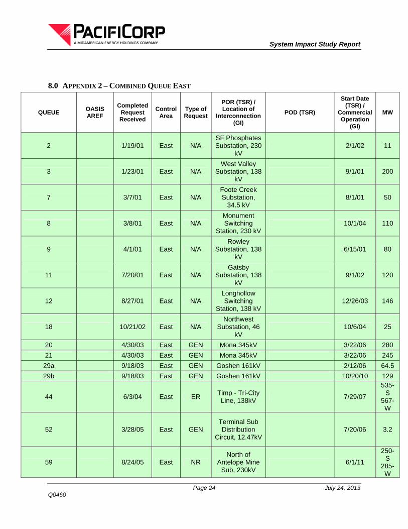
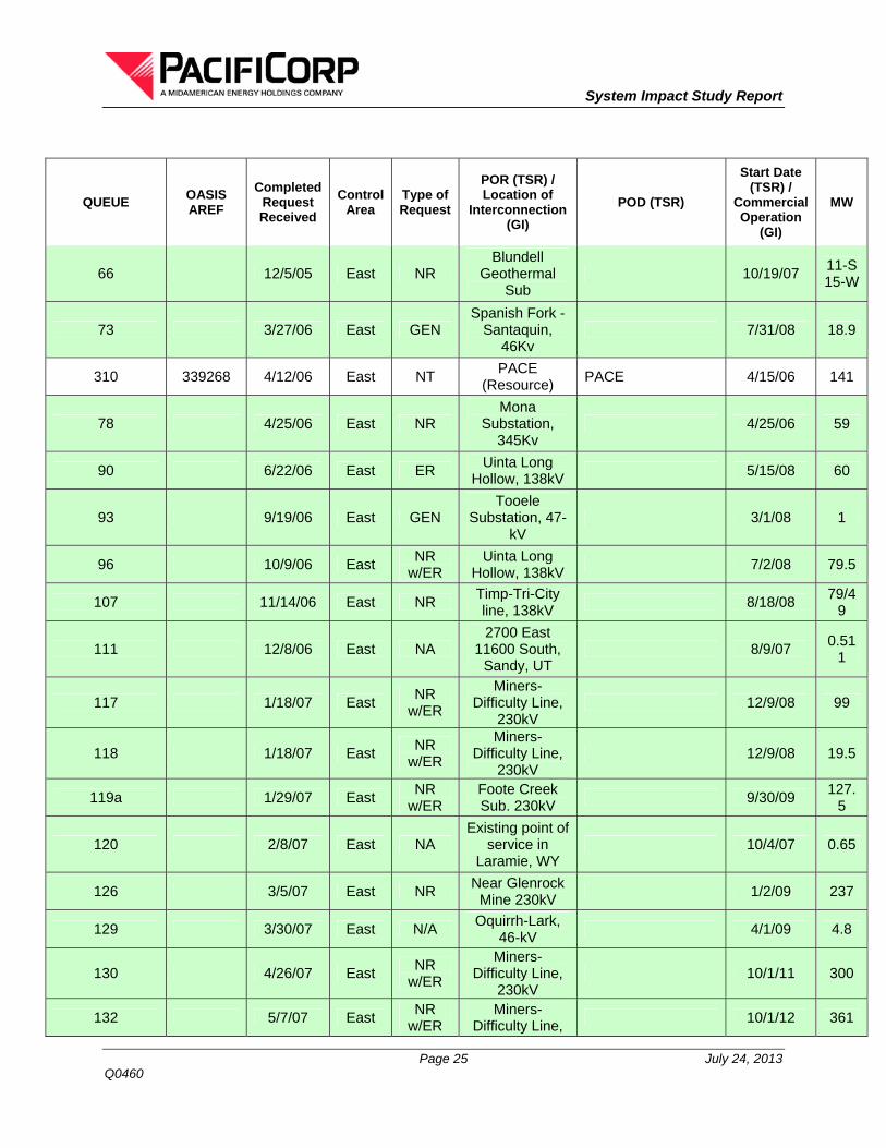
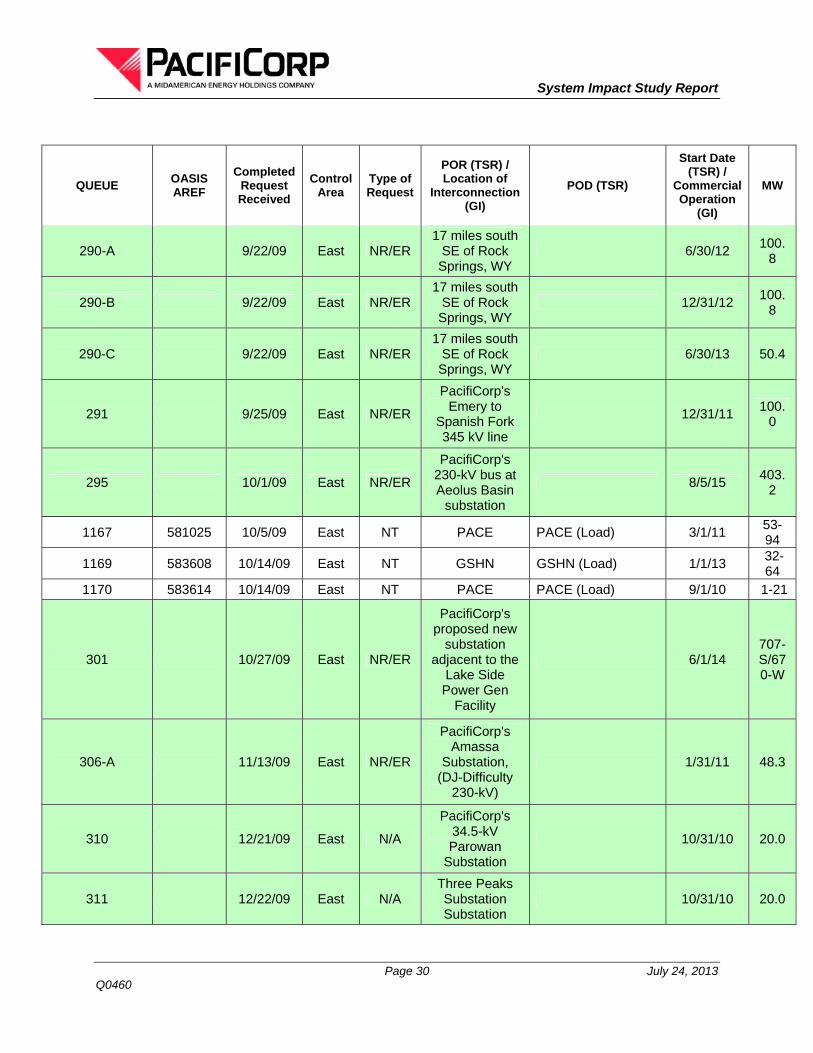
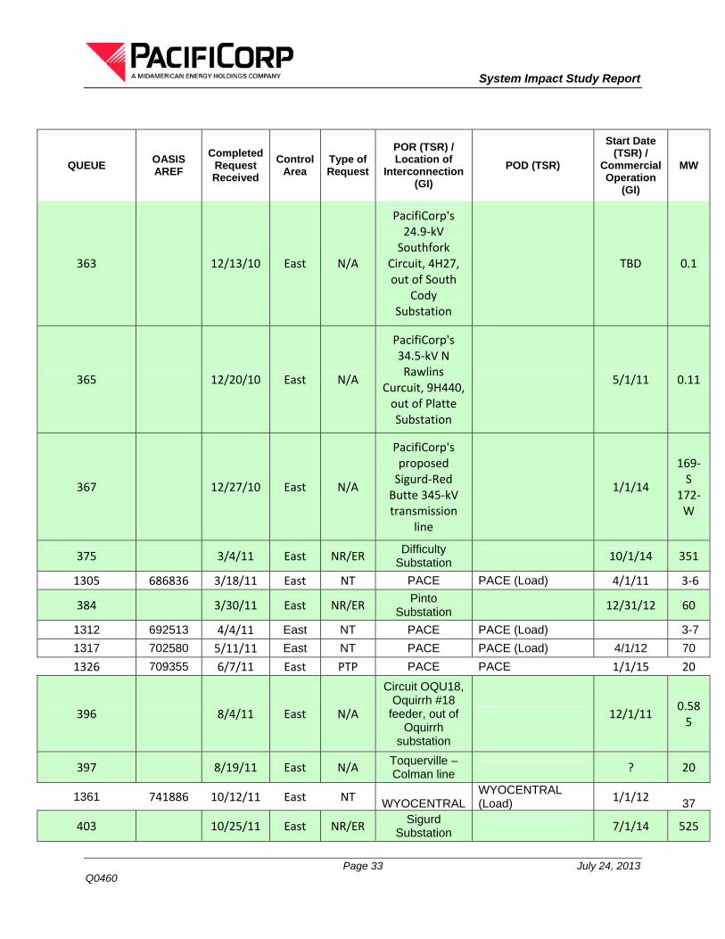
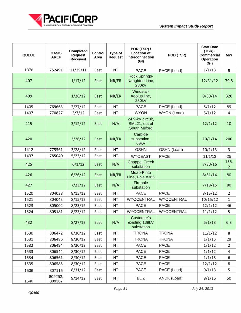
8.0 APPENDIX 2 – COMBINED QUEUE EAST
QUEUE OASIS AREF
Completed Request Received
Control Area
Type of Request
POR (TSR) / Location of
Interconnection (GI)
POD (TSR)
Start Date (TSR) /
Commercial Operation
(GI)
MW
2 1/19/01 East N/A SF Phosphates Substation, 230
kV 2/1/02 11
3 1/23/01 East N/A West Valley
Substation, 138 kV
9/1/01 200
7 3/7/01 East N/A Foote Creek Substation,
34.5 kV 8/1/01 50
8 3/8/01 East N/A Monument Switching
Station, 230 kV 10/1/04 110
9 4/1/01 East N/A Rowley
Substation, 138 kV
6/15/01 80
11 7/20/01 East N/A Gatsby
Substation, 138 kV
9/1/02 120
12 8/27/01 East N/A Longhollow Switching
Station, 138 kV 12/26/03 146
18 10/21/02 East N/A Northwest
Substation, 46 kV
10/6/04 25
20 4/30/03 East GEN Mona 345kV 3/22/06 280
21 4/30/03 East GEN Mona 345kV 3/22/06 245
29a 9/18/03 East GEN Goshen 161kV 2/12/06 64.5
29b 9/18/03 East GEN Goshen 161kV 10/20/10 129
44 6/3/04 East ER Timp - Tri-City Line, 138kV
7/29/07
535-S
567-W
52 3/28/05 East GEN Terminal Sub Distribution
Circuit, 12.47kV 7/20/06 3.2
59 8/24/05 East NR North of
Antelope Mine Sub, 230kV
6/1/11
250-S
285-W
System Impact Study Report
Page 25 July 24, 2013 Q0460
QUEUE OASIS AREF
Completed Request Received
Control Area
Type of Request
POR (TSR) / Location of
Interconnection (GI)
POD (TSR)
Start Date (TSR) /
Commercial Operation
(GI)
MW
66 12/5/05 East NR Blundell
Geothermal Sub
10/19/07 11-S 15-W
73 3/27/06 East GEN Spanish Fork -
Santaquin, 46Kv
7/31/08 18.9
310 339268 4/12/06 East NT PACE
(Resource) PACE 4/15/06 141
78 4/25/06 East NR Mona
Substation, 345Kv
4/25/06 59
90 6/22/06 East ER Uinta Long
Hollow, 138kV 5/15/08 60
93 9/19/06 East GEN Tooele
Substation, 47-kV
3/1/08 1
96 10/9/06 East NR
w/ER Uinta Long
Hollow, 138kV 7/2/08 79.5
107 11/14/06 East NR Timp-Tri-City line, 138kV
8/18/08 79/4
9
111 12/8/06 East NA 2700 East
11600 South, Sandy, UT
8/9/07 0.51
1
117 1/18/07 East NR
w/ER
Miners-Difficulty Line,
230kV 12/9/08 99
118 1/18/07 East NR
w/ER
Miners-Difficulty Line,
230kV 12/9/08 19.5
119a 1/29/07 East NR
w/ER Foote Creek Sub. 230kV
9/30/09 127.
5
120 2/8/07 East NA Existing point of
service in Laramie, WY
10/4/07 0.65
126 3/5/07 East NR Near Glenrock
Mine 230kV 1/2/09 237
129 3/30/07 East N/A Oquirrh-Lark,
46-kV 4/1/09 4.8
130 4/26/07 East NR
w/ER
Miners-Difficulty Line,
230kV 10/1/11 300
132 5/7/07 East NR
w/ER Miners-
Difficulty Line, 10/1/12 361
System Impact Study Report
Page 26 July 24, 2013 Q0460
QUEUE OASIS AREF
Completed Request Received
Control Area
Type of Request
POR (TSR) / Location of
Interconnection (GI)
POD (TSR)
Start Date (TSR) /
Commercial Operation
(GI)
MW
230kV
135 5/22/07 East NR
w/ER Dave Johnston Plant, 230kV
10/1/12 500
136 5/22/07 East NR
w/ER Windstar Plant,
230-kV 10/1/13 500
138 5/22/07 East N/A Green River 12 circuit, 12.5kV
5/22/09 0.57
5
139 5/25/07 East N/A University
Substation, 46kV
10/9/09 7.6
150 7/13/07 East N/A
PacifiCorp's 24.9-kV Circuit, QRY15, out of
Quarry Substation
6/18/09 1
153 8/8/07 East NR
w/ER
Dave Johnston-Yellowcake Line, 230-kV
10/28/10 200.
5
154 8/10/07 East N/A Goshen-Ucon
Line, 69-kV 4/30/12 19.8
161 9/4/07 East N/A 14.4-kV Circuit out of Pinedale
Substation 1/22/09 0.05
162 9/28/07 East N/A
PacifiCorp's 24.9-kV Circuit, SML21, out of South Milford
Substation
2/6/09 10-S 10.5-
W
165 10/12/07 East N/A 3474 N. 3rd
Street 3/11/08 0.03
171 11/8/07 East N/A
PacifiCorp's 69-kV, Sand Hills Line between
Casper & Platte Junction
12/25/09 19.5
172a 11/19/07 East NE
w/ER
Firehold - Flaming Gorge,
230 kV line 6/1/12 150
172b 11/19/07 East NE
w/ER
Firehold - Flaming Gorge,
230 kV line 4/1/13 150
System Impact Study Report
Page 27 July 24, 2013 Q0460
QUEUE OASIS AREF
Completed Request Received
Control Area
Type of Request
POR (TSR) / Location of
Interconnection (GI)
POD (TSR)
Start Date (TSR) /
Commercial Operation
(GI)
MW
173 11/20/07 East NE
w/ER 230-kV Firehole
Substation 6/1/12 150
175 12/7/07 East NE
w/ER
Craven Creek to Chappel
Creek 230 kV 11/30/12 150
184 1/7/08 East NE
w/ER
Miners-Difficulty Line,
230kV 10/1/12 99
185 1/7/08 East NE
w/ER
Miners-Difficulty Line,
230kV 10/1/12 98
186 1/7/08 East NE
w/ER
Miners-Difficulty Line,
230kV 10/1/12 99
191 1/25/08 East NR
w/ER
PAC's 230 kV Jim Bridger -
Aeolus 8/1/14 500
199 2/20/08 East NR
PacifiCorp's proposed 230-
kV Aeolus Substation
12/1/14 200
200 2/20/08 East NR
PacifiCorp's proposed 230-
kV Aeolus Substation
12/1/14 100
201 2/20/08 East NR
PacifiCorp's proposed 230-
kV Aeolus Substation
12/31/15 100
203 2/26/08 East NR
w/ER
Shirley-Basin Substation on
the PacifiCorp's 230-kV Miners-Difficulty Line
9/30/10 111
213 4/22/08 West N/A
Bernice #22 circuit out of
Bernice Substation
8/4/09 0.3
214 4/24/08 East N/A Pinedale Circuit
#23 2/18/09 1.96
System Impact Study Report
Page 28 July 24, 2013 Q0460
QUEUE OASIS AREF
Completed Request Received
Control Area
Type of Request
POR (TSR) / Location of
Interconnection (GI)
POD (TSR)
Start Date (TSR) /
Commercial Operation
(GI)
MW
220 5/12/08 East NR
w/ER
Latigo Substation between
Casper and Windstar 230-
kV line
11/20/09 100.
5
947 493092 5/23/08 East NT PACE
(Resource) PACE 6/1/12
316, 562
224a 5/27/08 East NR
w/ER
PacifiCorp's 345 kV Mona
substation 5/15/15 320
224b 5/27/08 East NR
w/ER
PacifiCorp's 345 kV Mona
substation 5/15/15 230
252 11/25/08 East N/A Customer's
existing 46-kV system
3/1/09 0.23
253 11/26/08 East N/A
1600 West B Avenue, Utah
Industrial Depot, Tooele,
Utah
2/20/09 0.05
255 12/23/08 West NR
w/ER
3.2 miles NE of PacifiCorp's
Goshen Substation
5/20/12 151.
8
256 1/14/09 West NA HPS 12 Circuit 4/15/09 1.69
6
267-A 4/13/09 East NR
w/ER
PacifiCorp's 345-kV Jim
Bridger Power Plant, Point of
Rocks, WY
6/12/10 18.3/
22
267-B 4/13/09 East NR
w/ER
PacifiCorp's 345-kV Jim
Bridger Power Plant, Point of
Rocks, WY
5/5/13 18.3/
22
System Impact Study Report
Page 29 July 24, 2013 Q0460
QUEUE OASIS AREF
Completed Request Received
Control Area
Type of Request
POR (TSR) / Location of
Interconnection (GI)
POD (TSR)
Start Date (TSR) /
Commercial Operation
(GI)
MW
267-C 4/13/09 East NR
w/ER
PacifiCorp's 345-kV Jim
Bridger Power Plant, Point of
Rocks, WY
5/22/11 18.3/
22
267-D 4/13/09 East NR
w/ER
PacifiCorp's 345-kV Jim
Bridger Power Plant, Point of
Rocks, WY
5/27/12 18.3/
22
270-A 4/30/09 East ER
PacifiCorp's Huntington
Power Plant, Huntington, UT
11/21/10 16.2
270-B 4/30/09 East ER
PacifiCorp's Huntington
Power Plant, Huntington, UT
4/30/15 16.2
271-A 4/30/09 East ER
PacifiCorp's Hunter Power
Plant, Castledale, UT
4/13/10 17.0
271-B 4/30/09 East ER
PacifiCorp's Hunter Power
Plant, Castledale, UT
4/30/15 17.0
271-C 4/30/09 East ER
PacifiCorp's Hunter Power
Plant, Castledale, UT
4/30/16 8.7
272 5/14/09 East NR
w/ER
PacifCorp's proposed new substation on the 230-kV
Miners-Difficulty Line
9/30/10 12.0
1145 563529 6/26/09 East NT PACEW PACEW 4/1/10 25.0
282 8/7/09 East N/A
PacifiCorp's 138/46-kV
Lampo Substation
9/25/09 0.0360
System Impact Study Report
Page 30 July 24, 2013 Q0460
QUEUE OASIS AREF
Completed Request Received
Control Area
Type of Request
POR (TSR) / Location of
Interconnection (GI)
POD (TSR)
Start Date (TSR) /
Commercial Operation
(GI)
MW
290-A 9/22/09 East NR/ER 17 miles south
SE of Rock Springs, WY
6/30/12 100.
8
290-B 9/22/09 East NR/ER 17 miles south
SE of Rock Springs, WY
12/31/12 100.
8
290-C 9/22/09 East NR/ER 17 miles south
SE of Rock Springs, WY
6/30/13 50.4
291 9/25/09 East NR/ER
PacifiCorp's Emery to
Spanish Fork 345 kV line
12/31/11 100.
0
295 10/1/09 East NR/ER
PacifiCorp's 230-kV bus at Aeolus Basin
substation
8/5/15 403.
2
1167 581025 10/5/09 East NT PACE PACE (Load) 3/1/11 53-94
1169 583608 10/14/09 East NT GSHN GSHN (Load) 1/1/13 32-64
1170 583614 10/14/09 East NT PACE PACE (Load) 9/1/10 1-21
301 10/27/09 East NR/ER
PacifiCorp's proposed new
substation adjacent to the
Lake Side Power Gen
Facility
6/1/14 707-S/670-W
306-A 11/13/09 East NR/ER
PacifiCorp's Amassa
Substation, (DJ-Difficulty
230-kV)
1/31/11 48.3
310 12/21/09 East N/A
PacifiCorp's 34.5-kV Parowan
Substation
10/31/10 20.0
311 12/22/09 East N/A Three Peaks Substation Substation
10/31/10 20.0
System Impact Study Report
Page 31 July 24, 2013 Q0460
QUEUE OASIS AREF
Completed Request Received
Control Area
Type of Request
POR (TSR) / Location of
Interconnection (GI)
POD (TSR)
Start Date (TSR) /
Commercial Operation
(GI)
MW
313 12/22/09 East NR
PacifiCorp's 138 kV switch
132 located 3/4 mile N of the generation facility site
12/31/12 25-S 65-W
314 12/31/09 East NR
PacifiCorp's 34.5-kV West
Cedar Substation
12/31/10 20.0
1190 603498 2/15/10 East NT PACE PACE (Load) 7/1/10 1-12
323-A 3/3/10 East NR/ER
PacifiCorp's 230-kV
Sunbeam Substation
5/31/11 21.6
323-B 3/3/10 East NR/ER
PacifiCorp's 230-kV
Sunbeam Substation
11/30/11 21.6
324 3/8/10 East N/A
Parowan - Rocky
Mountain Power
Substation
8/10/12 40.0
1202 614127 4/9/10 East NT WYOEAST WYODAK (Load) 11/17/10 35.0
332 4/29/10 East N/A
PacifiCorp's 24.9-kV circuit, SML21, out of South Milford
Substation
6/1/11 2.8
1209 617716 5/3/10 East NT GSHN GSHN (Load) 1/1/13 11-39
1210 618363 5/3/10 East PTP PACE MDWP 6/1/11 3.0
1214 618940 5/14/10 East NT WYOCENTRALWYOCENTRAL (Load)
10/1/10 10.0
333 5/17/10 East N/A
PacifiCorp's 24.9 kV circuit, SML21, out of South Milford
Substation
10/1/11 2.8
1215 620282 5/19/10 East NT PACE PACE (Load) 6/30/11 14-17
System Impact Study Report
Page 32 July 24, 2013 Q0460
QUEUE OASIS AREF
Completed Request Received
Control Area
Type of Request
POR (TSR) / Location of
Interconnection (GI)
POD (TSR)
Start Date (TSR) /
Commercial Operation
(GI)
MW
1216 621679 5/27/10 East NT PACE PACE (Load) 7/1/10 8-15
335 6/1/10 East NR/ER
PacifiCorp's Amassa
Substation, (DJ-Difficulty
230-kV)
3/1/12 49.5
341 6/10/10 East NR/ER
PacifiCorp's Goshen
Substation at 161 kV
11/1/12 120.
0
1223 625986 6/17/10 East NT WYOEAST WYOEAST (Load) 1/1/11 2.0
1224 626003 6/17/10 East NT PACE PACE (Load) 10/1/10 2.0
1225 626275 6/17/10 East NT WYOEAST WYOEAST (Load) 12/10/10 2-9
1229 626453 6/23/10 East NT PACE PACE (Load) 7/1/11 23-150
1230 626791 6/23/10 East NT PACE PACE (Load) 2/24/11 15-30
1231 626864 6/23/10 East NT PACE PACE (Load) 11/1/10 6.0
1236 630525 7/15/10 East NT WYOEAST WYOEAST (Load) 6/1/11 3-15
1237 634125 8/3/10 East NT PACE PACE (Load) 10/1/10 3-8
348 8/9/10 East N/A
PacifiCorp's 24.9-kV Circuit, QRY15, out of
Quarry Substation
4/30/11 0.22
1238 635532 8/9/10 East NT WYOEAST WYOEAST (Load) 7/31/13 13-67
1241 637972 8/20/10 East NT PACE PACE (Load) 7/1/13 21.0
1248 645170 9/22/10 East PTP PACE MDWP 1/1/12 3.0
1251 645781 9/29/10 East NT PACE PACE (Load) 10/1/11 2-4
1252 645790 9/29/10 East NT PACE PACE (Load) 12/1/10 1-8
1256 648008 10/8/10 East NT PACE
(Resource) PACE 5/1/14
660.0
1258 648377 10/12/10 East NT PACE PACE (Load) 5/1/13 13.0
1263 656398 11/9/10 East NT DJ WYOEAST (Load) 12/1/10 1.0
1305 686836 3/18/11 East NT PACE PACE (Load) 4/1/11 3‐6
384 3/30/11 East NR/ER Pinto
Substation 12/31/12 60
1312 692513 4/4/11 East NT PACE PACE (Load) 3-7
1317 702580 5/11/11 East NT PACE PACE (Load) 4/1/12 70
1326 709355 6/7/11 East PTP PACE PACE 1/1/15 20
396 8/4/11 East N/A
Circuit OQU18, Oquirrh #18
feeder, out of Oquirrh
substation
12/1/11 0.585
397 8/19/11 East N/A Toquerville – Colman line
? 20
1361 741886 10/12/11 East NT WYOCENTRALWYOCENTRAL (Load) 1/1/12 37
403 10/25/11 East NR/ER Sigurd
Substation 7/1/14 525
System Impact Study Report
Page 34 July 24, 2013 Q0460
QUEUE OASIS AREF
Completed Request Received
Control Area
Type of Request
POR (TSR) / Location of
Interconnection (GI)
POD (TSR)
Start Date (TSR) /
Commercial Operation
(GI)
MW
1376 752491 11/29/11 East NT PACE PACE (Load) 1/1/13 5
407 1/17/12 East NR/ER Rock Springs-Naughton Line,
230kV 12/31/12 79.8
409 1/26/12 East NR/ER Windstar-
Aeolus line, 230kV
9/30/14 320
1405 769663 2/27/12 East NT PACE PACE (Load) 5/1/12 89
1407 770827 3/7/12 East NT WYON WYON (Load) 5/1/12 4
415 3/12/12 East N/A 24.9-kV circuit, SML21, out of South Milford
12/1/12 10
420 3/26/12 East NR/ER Carbide
substation, 69kV
10/1/14 200
1412 775561 3/28/12 East NT GSHN GSHN (Load) 10/1/13 3
1497 785040 5/23/12 East NT WYOEAST PACE 11/1/13 25
425 6/1/12 East N/A Chappel Creek
substation 7/30/16
156.2
426 6/26/12 East NR/ER Moab-Pinto
Line, Pole #365 8/31/14 80
427 7/23/12 East N/A Firehole
substation 7/18/15 80
1520 804038 8/15/12 East NT PACE PACE 8/15/12 2
1521 804043 8/15/12 East NT WYOCENTRAL WYOCENTRAL 10/15/12 1
1523 805002 8/23/12 East NT PACE PACE 12/1/12 46
1524 805181 8/23/12 East NT WYOCENTRAL WYOCENTRAL 11/1/12 5
432 8/27/12 East N/A Customer's
existing 138kV substation
5/1/13 6.3
1530 806472 8/30/12 East NT TRONA TRONA 11/1/12 8
1531 806486 8/30/12 East NT TRONA TRONA 1/1/15 29
1532 806494 8/30/12 East NT PACE PACE 1/1/12 2
1533 806544 8/30/12 East NT PACE PACE 1/1/12 4
1534 806561 8/30/12 East NT PACE PACE 1/1/13 6
1535 806585 8/30/12 East NT PACE PACE 12/1/12 8
1536 807115 8/31/12 East NT PACE PACE (Load) 9/1/13 5
1540 809252; 809367
9/14/12 East NT BOZ ANDK (Load) 8/1/16 50
System Impact Study Report
Page 35 July 24, 2013 Q0460
QUEUE OASIS AREF
Completed Request Received
Control Area
Type of Request
POR (TSR) / Location of
Interconnection (GI)
POD (TSR)
Start Date (TSR) /
Commercial Operation
(GI)
MW
1541 809254; 809362
9/14/12 East NT BOZ ANDK (Load) 8/1/16 100
1542 809337; 809374
9/14/12 East NT BOZ ANDK (Load) 1/1/13 20
1543 809340; 809375
9/14/12 East NT BOZ ANDK (Load) 1/1/15 24
1544 809347; 809376
9/14/12 East NT BOZ ANDK (Load) 2/1/15 3
1545 809353; 809378
9/14/12 East NT BOZ ANDK (Load) 1/1/16 3
1546 809355; 809380
9/14/12 East NT BOZ ANDK (Load) 9/1/16 3
1547 809357; 809382
9/14/12 East NT BOZ ANDK (Load) 1/1/17 11
1548 809397 ; 809398
9/14/12 East NT BOZ ANDK (Load) 1/1/13 30
437 9/17/12 East N/A
Circuit PRS13, Preston #13, out of Preston
substation
4/17/14 0.5
438 9/18/12 East N/A
Customer's electric system
from Tooele Depot
substation
4/1/13 1.75
439 9/18/12 East N/A
Customer's electric system
from Tooele Depot
substation
4/1/13 1.56
442 10/11/12 East N/A
RIGBY-REXBURG
TAP TO WEBSTER
9/30/14 5.6
1578 77610461 12/6/12 East NT Sunbeam BRDY 3/1/13 45
450 12/21/12 East N/A Pavant
substation 3/15/14 50
451 1/2/13 East N/A
Circuit CLM11, Coleman #11,
out of Coleman substation
12/13/13 3
1591 77717778 1/2/13 East PTP PACE 4C 1/1/14 66
System Impact Study Report
Page 36 July 24, 2013 Q0460
QUEUE OASIS AREF
Completed Request Received
Control Area
Type of Request
POR (TSR) / Location of
Interconnection (GI)
POD (TSR)
Start Date (TSR) /
Commercial Operation
(GI)
MW
1592 77717792 1/2/13 East PTP PACE 4C 1/1/14 100
453 1/7/13 East N/A
Circuit CLF11, CLIFTON #11
DAYTON & BANIDA, out of
Clifton substation
12/31/13 1.6
454 1/10/13 East N/A
Circuit WCD28, West Cedar #28, out of West Cedar substation
6/30/14 3
455 1/10/13 East N/A
Circuit WCD28, West Cedar #28, out of West Cedar substation
6/30/14 3
456 1/10/13 East N/A
Circuit BKl12, Brooklawn #12,
out of Brooklawn substation
6/30/14 2.1
457 1/10/13 East N/A
Circuit BKl11, Brooklawn #11,
out of Brooklawn substation
6/30/14 2.1
1599 77699698 1/16/13 East NT GSHN GSHN 11/1/13 1
459 1/18/13 East N/A
Circuit SML12, South Milford
#12, out of South Milford
substation
6/30/14 3
460 1/18/13 East NR/ER Pavant-Gonder Transmission
Line 12/31/14 160
Large Generator Interconnection
System Impact Study Report
Dynamic Stability Study
Completed for
LGIQ# Q0460
Proposed Interconnection 230 kV Gonder - Pavant Transmission Line
at or near Pole # 554
July 24, 2013
i
Table of Contents
Executive Summary i
1. Description of Project 1-1 2. Study Assumptions 2-1 3. Transient Analysis 3-1 4. Conclusions 4-1 5. Appendices 5-1
A. Transient Stability Plots A-1
ii
Executive Summary “Interconnection Customer” proposed interconnecting 159.8 MW of new generation to PacifiCorp’s (“Transmission Provider”) existing 230 kV Gonder – Pavant transmission line at or near pole 554 located in Millard County, Utah. The project (“Project”) will consist of 94 GE 1.7 MW wind turbine generators for a total output of 159.8 MWs. The requested commercial operation date is approximately December 31, 2015. Interconnection Customer will operate this generator as a Qualified Facility as defined by the Public Utility Regulatory Policies Act of 1978 (PURPA). The Transmission Provider has assigned the project “Q0460.”
Transient stability analysis was simulated for various local area disturbances in the 230 kV and 345 kV transmission network with 2015 system conditions modeled. Results identified that with the GE 1.7 MW generator model; all wind turbines will ride through ALL simulated local area contingencies.
The Project is required to operate in the voltage control mode maintaining the voltage at the Point of Interconnection based on voltage schedule provided by the Transmission Provider. Along with the voltage control the Project should at least have sufficient reactive capability to enable the facility to achieve unity power factor under different operating conditions. It is the responsibility of the interconnection customer to ensure that the project is capable of achieving unity power factor during all conditions.
Note, project modeling is based on data provided by the developer and/or the developer’s equipment suppliers.
2- 1
1. Description of Project
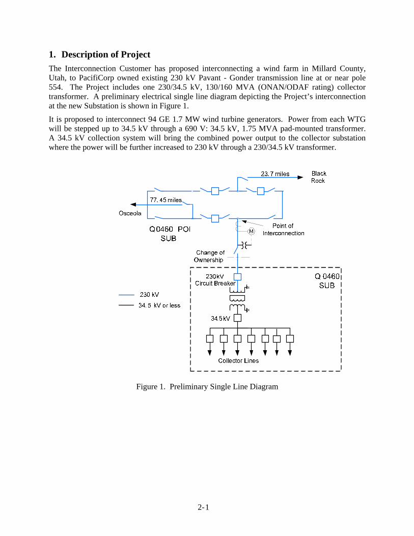
The Interconnection Customer has proposed interconnecting a wind farm in Millard County, Utah, to PacifiCorp owned existing 230 kV Pavant - Gonder transmission line at or near pole 554. The Project includes one 230/34.5 kV, 130/160 MVA (ONAN/ODAF rating) collector transformer. A preliminary electrical single line diagram depicting the Project’s interconnection at the new Substation is shown in Figure 1.
It is proposed to interconnect 94 GE 1.7 MW wind turbine generators. Power from each WTG will be stepped up to 34.5 kV through a 690 V: 34.5 kV, 1.75 MVA pad-mounted transformer. A 34.5 kV collection system will bring the combined power output to the collector substation where the power will be further increased to 230 kV through a 230/34.5 kV transformer.
Figure 1. Preliminary Single Line Diagram
2- 2
2. Study Assumptions
The PSS/E version 32.1.2 program was used to evaluate system stability for each of the faults described in Table 1. In addition, the following assumptions were used in performing this study.
Study Period: The 2017 Heavy Summer WECC transmission power flow and dynamics data was used for this analysis.
Study Area: The study area was limited to the Project and the surrounding 230 kV and 345 kV transmission system in Utah. The underlying transmission system between Pavant and Gonder was included in the study case.
Contingencies: The study simulated disturbances tabulated in Table 1.
1 Three-phase fault at the Pavant 230 kV bus followed by loss of the Pavant – Blackrock 230 kV circuit (4 cycles).
2 Three-phase fault at the Q460 230 kV POI bus followed by loss of the Q460 – Blackrock 230 kV circuit (4 cycles).
3 Three-phase fault at the Q460 230 kV POI bus followed by loss of the Q460 – Osceola 230 kV circuit (4 cycles).
4 Three-phase fault at the Osceola 230 kV bus followed by loss of the Osceola - Gonder 230 kV circuit (4 cycles).
5 Three-phase fault at the Gonder 230 kV bus followed by loss of the Gonder - IPP 230 kV circuit (4 cycles).
6 Three-phase fault at the Gonder 230 kV bus followed by loss of the Gonder - Machacek 230 kV circuit (4 cycles).
7 Three-phase fault at the Gonder 345 kV bus followed by loss of the Gonder - Robinson 345 kV circuit (3 cycles).
8 Three-phase fault at the Robinson 345 kV bus followed by loss of the Robinson - Falcon 345 kV circuit (3 cycles).
9 Three-phase fault at the Robinson 345 kV bus followed by loss of the Robinson – H. Allen 500 kV circuit (3 cycles).
10 Three-phase fault at the Midpoint 500 kV bus followed by loss of the Midpoint – Hemingway 500 kV circuit (3 cycles).
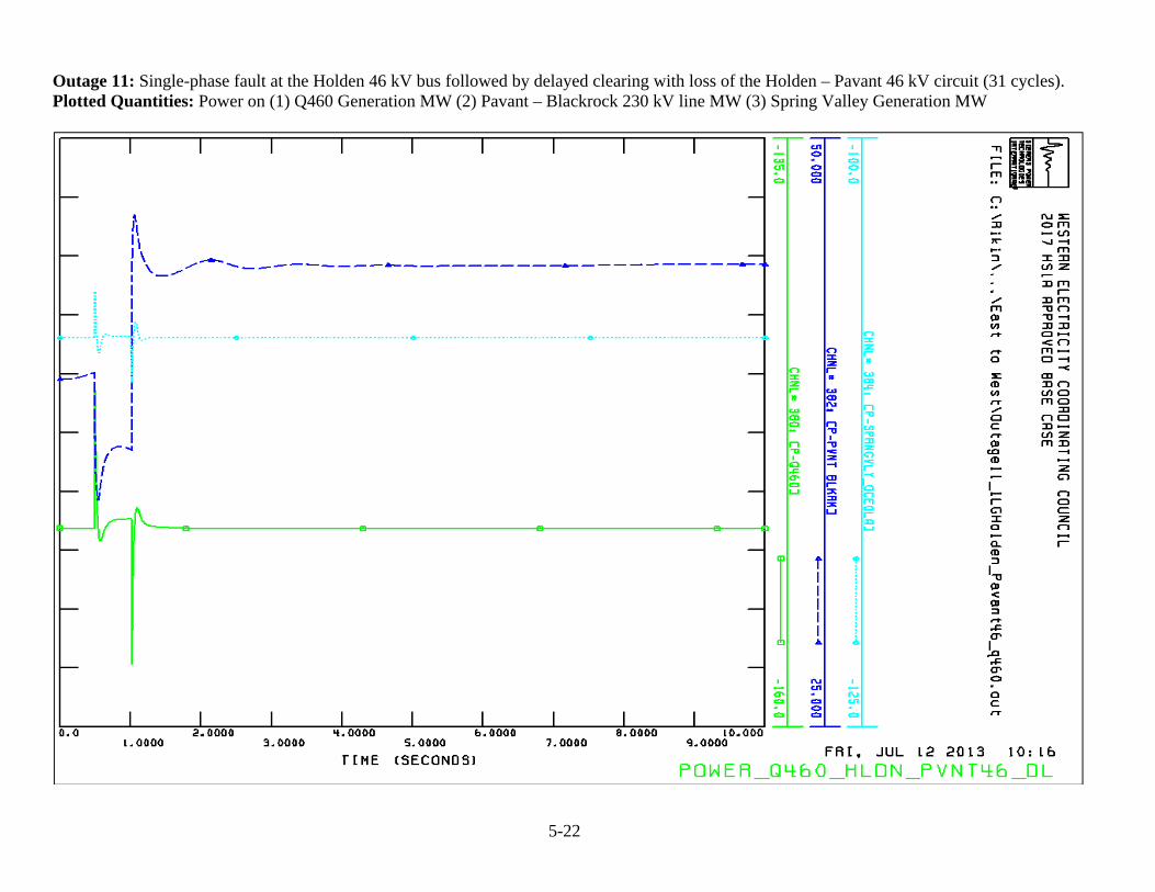
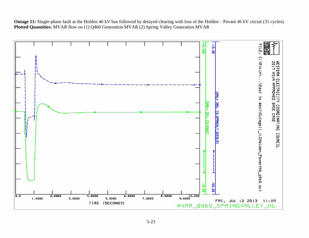
11 Single-phase fault at the Holden 46 kV bus followed by delayed clearing with loss of the Holden – Pavant 46 kV circuit (31 cycles).
2- 3
Other Assumptions:
Path 32 was increased to 330 MW from east-to-west with the total flow into Gonder at 433 MW in order to stress the system around the project bus.
Data provided for the collector system 230/34.5 kV transformer was 130/160 MVA (ONAN/ODAF) with 12.8% impedance.
Transient stability simulations were performed out to 10 seconds in order to determine system damping.
The maximum reactive power capability of each machine is specified at a power factor of +/- 0.95 at rated active power.
The GE 1.7 MW turbine is required to have zero voltage ride-through protection capability; therefore, the turbine is designed to stay connected to the grid in the case of severe faults. The following figure illustrates the zero voltage ride-through capability.
Figure 2. Zero Voltage Ride-through Capability
0
0.1
0.2
0.3
0.4
0.5
0.6
0.7
0.8
0.9
1
‐0.5 0.5 1.5 2.5 3.5 4.5 5.5 6.5 7.5 8.5 9.5
Voltage (pu)
Time (seconds)
ZVRT Control
3-1
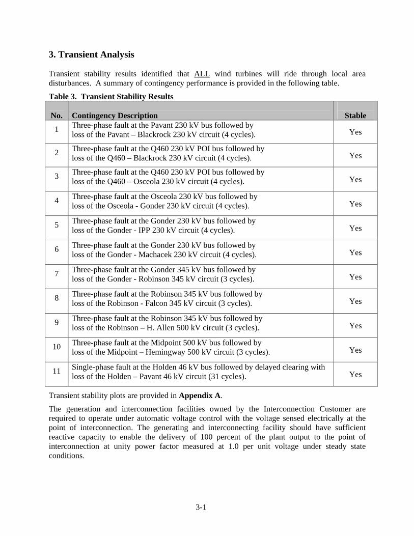
3. Transient Analysis Transient stability results identified that ALL wind turbines will ride through local area disturbances. A summary of contingency performance is provided in the following table.
Table 3. Transient Stability Results
No. Contingency Description
Stable
1 Three-phase fault at the Pavant 230 kV bus followed by loss of the Pavant – Blackrock 230 kV circuit (4 cycles). Yes
2 Three-phase fault at the Q460 230 kV POI bus followed by loss of the Q460 – Blackrock 230 kV circuit (4 cycles). Yes
3 Three-phase fault at the Q460 230 kV POI bus followed by loss of the Q460 – Osceola 230 kV circuit (4 cycles). Yes
4 Three-phase fault at the Osceola 230 kV bus followed by loss of the Osceola - Gonder 230 kV circuit (4 cycles). Yes
5 Three-phase fault at the Gonder 230 kV bus followed by loss of the Gonder - IPP 230 kV circuit (4 cycles). Yes
6 Three-phase fault at the Gonder 230 kV bus followed by loss of the Gonder - Machacek 230 kV circuit (4 cycles). Yes
7 Three-phase fault at the Gonder 345 kV bus followed by loss of the Gonder - Robinson 345 kV circuit (3 cycles). Yes
8 Three-phase fault at the Robinson 345 kV bus followed by loss of the Robinson - Falcon 345 kV circuit (3 cycles). Yes
9 Three-phase fault at the Robinson 345 kV bus followed by loss of the Robinson – H. Allen 500 kV circuit (3 cycles). Yes
10 Three-phase fault at the Midpoint 500 kV bus followed by loss of the Midpoint – Hemingway 500 kV circuit (3 cycles). Yes
11 Single-phase fault at the Holden 46 kV bus followed by delayed clearing with loss of the Holden – Pavant 46 kV circuit (31 cycles). Yes
Transient stability plots are provided in Appendix A.
The generation and interconnection facilities owned by the Interconnection Customer are required to operate under automatic voltage control with the voltage sensed electrically at the point of interconnection. The generating and interconnecting facility should have sufficient reactive capacity to enable the delivery of 100 percent of the plant output to the point of interconnection at unity power factor measured at 1.0 per unit voltage under steady state conditions.
3-2
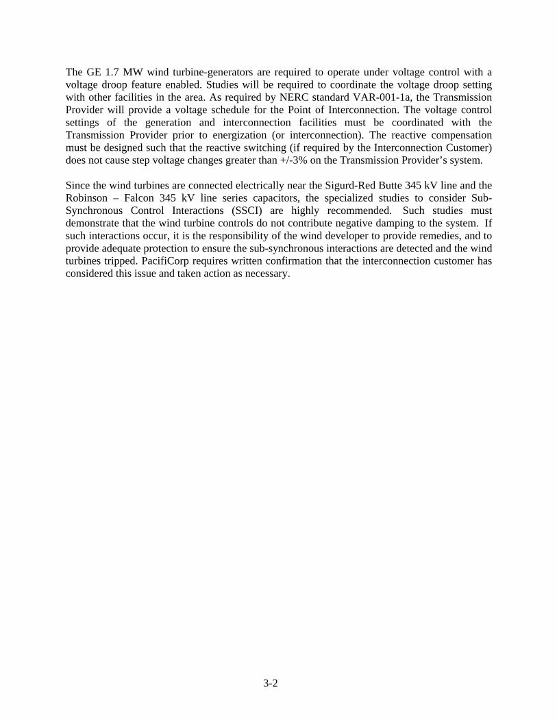
The GE 1.7 MW wind turbine-generators are required to operate under voltage control with a voltage droop feature enabled. Studies will be required to coordinate the voltage droop setting with other facilities in the area. As required by NERC standard VAR-001-1a, the Transmission Provider will provide a voltage schedule for the Point of Interconnection. The voltage control settings of the generation and interconnection facilities must be coordinated with the Transmission Provider prior to energization (or interconnection). The reactive compensation must be designed such that the reactive switching (if required by the Interconnection Customer) does not cause step voltage changes greater than +/-3% on the Transmission Provider’s system. Since the wind turbines are connected electrically near the Sigurd-Red Butte 345 kV line and the Robinson – Falcon 345 kV line series capacitors, the specialized studies to consider Sub-Synchronous Control Interactions (SSCI) are highly recommended. Such studies must demonstrate that the wind turbine controls do not contribute negative damping to the system. If such interactions occur, it is the responsibility of the wind developer to provide remedies, and to provide adequate protection to ensure the sub-synchronous interactions are detected and the wind turbines tripped. PacifiCorp requires written confirmation that the interconnection customer has considered this issue and taken action as necessary.
4-1
4. Conclusions
The following conclusions have been reached through this analysis: Addition of 94 GE 1.7 MW wind turbine generators interconnecting to the existing 230 kV
Pavant – Gonder transmission line at or near pole 554 does not result in transient instability. In addition, all wind turbines will ride through ALL simulated local area contingencies.
Simulation results are based on data provided by the Interconnection Customer as well as other model data available at the time of the study. The results can be used to help determine whether or not the Project facilities will meet the performance criteria including ride-through requirements which are identified in the Interconnection Agreement, and, in some cases, may indicate that additional equipment is required in order to meet these requirements. However, ultimately it is the Interconnection Customer’s responsibility to meet these requirements during actual operation on a daily basis and failure to do so can result in loss of interconnection privileges. Therefore, the results of these simulations should be regarded as informational rather than definitive, and do not relieve the Interconnection Customer of any performance responsibilities. Finally, if the assumptions utilized in this study significantly change, PacifiCorp reserves the right to perform a re-study. Significant changes include, but are not limited to, development of new models which may impact performance as well as changes to the base case assumptions for planned future but as yet uncommitted transmission line and generation facilities.
5-1
5. Appendices A. Transient Stability Plots
5-1
Outage 1: Three-phase fault at the Pavant 230 kV bus followed by loss of the Pavant – Blackrock 230 kV circuit (4 cycles). Plotted Quantities: Voltages at (1) Gonder 230 kV (2) Utah – Nev 230 kV (3) Pavant 230 kV (4) Blackrock 230 kV (5) Q460 POI 230 kV (6) Q460 Generator 0.7 kV
5-2
Outage 1: Three-phase fault at the Pavant 230 kV bus followed by loss of the Pavant – Blackrock 230 kV circuit (4 cycles). Plotted Quantities: Power on (1) Q460 Generation MW (2) Q460 Generation MVAR (3) Spring Valley Generation MW (4) Spring Valley Generation MVAR
5-3
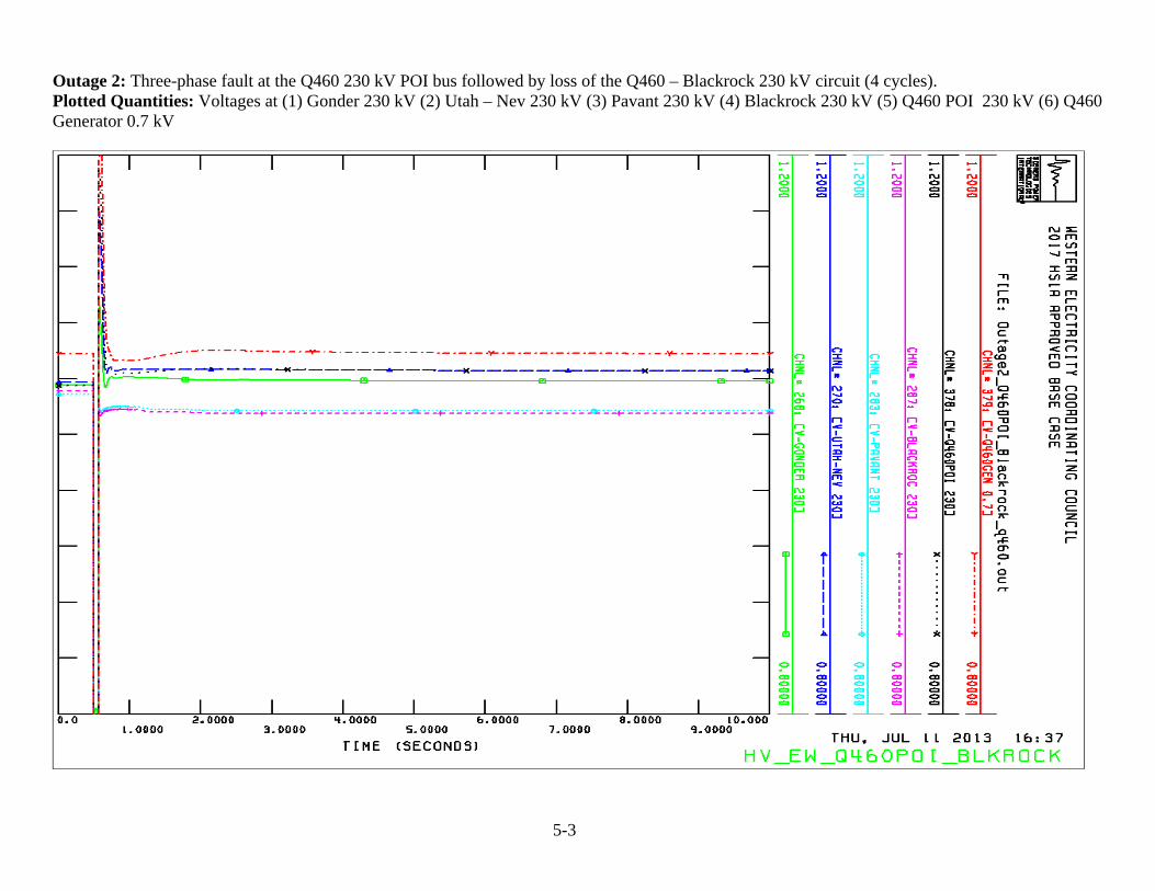
Outage 2: Three-phase fault at the Q460 230 kV POI bus followed by loss of the Q460 – Blackrock 230 kV circuit (4 cycles). Plotted Quantities: Voltages at (1) Gonder 230 kV (2) Utah – Nev 230 kV (3) Pavant 230 kV (4) Blackrock 230 kV (5) Q460 POI 230 kV (6) Q460 Generator 0.7 kV
5-4
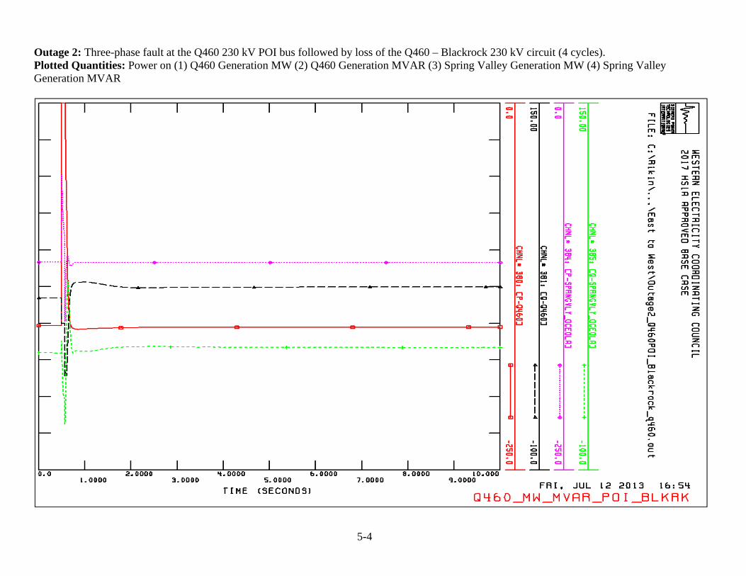
Outage 2: Three-phase fault at the Q460 230 kV POI bus followed by loss of the Q460 – Blackrock 230 kV circuit (4 cycles). Plotted Quantities: Power on (1) Q460 Generation MW (2) Q460 Generation MVAR (3) Spring Valley Generation MW (4) Spring Valley Generation MVAR
5-5
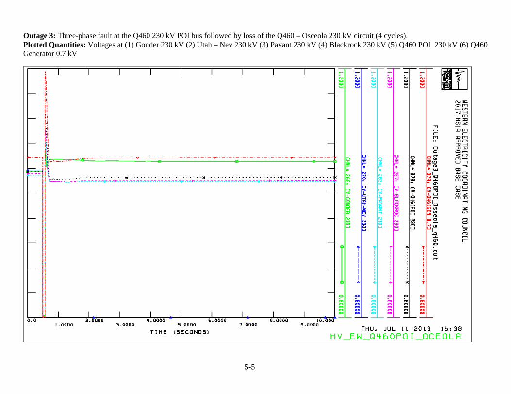
Outage 3: Three-phase fault at the Q460 230 kV POI bus followed by loss of the Q460 – Osceola 230 kV circuit (4 cycles). Plotted Quantities: Voltages at (1) Gonder 230 kV (2) Utah – Nev 230 kV (3) Pavant 230 kV (4) Blackrock 230 kV (5) Q460 POI 230 kV (6) Q460 Generator 0.7 kV
5-6
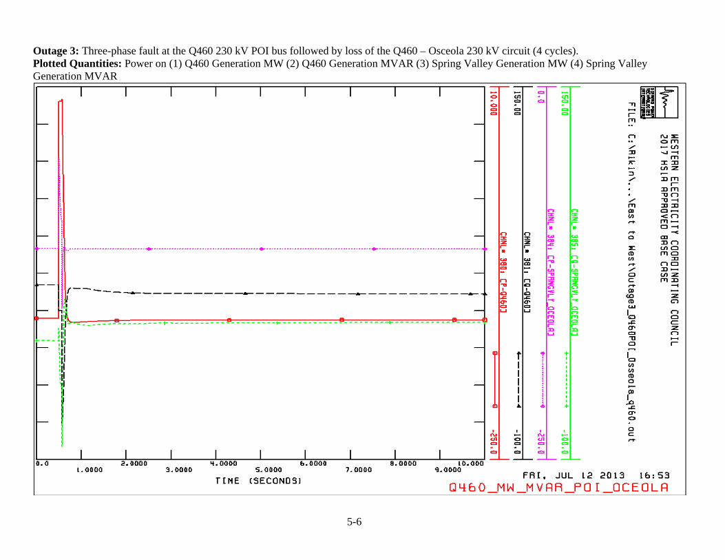
Outage 3: Three-phase fault at the Q460 230 kV POI bus followed by loss of the Q460 – Osceola 230 kV circuit (4 cycles). Plotted Quantities: Power on (1) Q460 Generation MW (2) Q460 Generation MVAR (3) Spring Valley Generation MW (4) Spring Valley Generation MVAR
5-7
Outage 4: Three-phase fault at the Osceola 230 kV bus followed by loss of the Osceola - Gonder 230 kV circuit (4 cycles). Plotted Quantities: Voltages at (1) Gonder 230 kV (2) Utah – Nev 230 kV (3) Pavant 230 kV (4) Blackrock 230 kV (5) Q460 POI 230 kV (6) Q460 Generator 0.7 kV
5-8
Outage 4: Three-phase fault at the Osceola 230 kV bus followed by loss of the Osceola - Gonder 230 kV circuit (4 cycles). Plotted Quantities: Power on (1) Q460 Generation MW (2) Q460 Generation MVAR (3) Spring Valley Generation MW (4) Spring Valley Generation MVAR
5-9
Outage 5: Three-phase fault at the Gonder 230 kV bus followed by loss of the Gonder - IPP 230 kV circuit (4 cycles). Plotted Quantities: Voltages at (1) Gonder 230 kV (2) Utah – Nev 230 kV (3) Pavant 230 kV (4) Blackrock 230 kV (5) Q460 POI 230 kV (6) Q460 Generator 0.7 kV
5-10
Outage 5: Three-phase fault at the Gonder 230 kV bus followed by loss of the Gonder - IPP 230 kV circuit (4 cycles). Plotted Quantities: Power on (1) Q460 Generation MW (2) Q460 Generation MVAR (3) Spring Valley Generation MW (4) Spring Valley Generation MVAR
5-11
Outage 6: Three-phase fault at the Gonder 230 kV bus followed by loss of the Gonder - Machacek 230 kV circuit (4 cycles). Plotted Quantities: Voltages at (1) Gonder 230 kV (2) Utah – Nev 230 kV (3) Pavant 230 kV (4) Blackrock 230 kV (5) Q460 POI 230 kV (6) Q460 Generator 0.7 kV
5-12
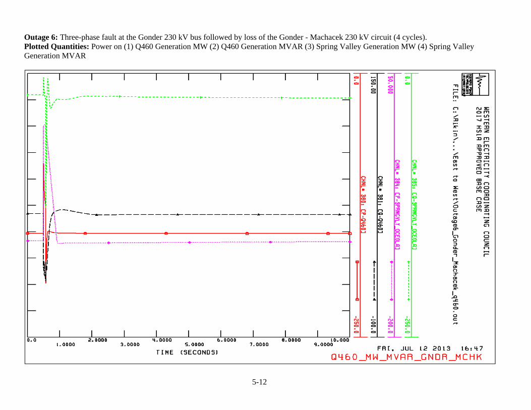
Outage 6: Three-phase fault at the Gonder 230 kV bus followed by loss of the Gonder - Machacek 230 kV circuit (4 cycles). Plotted Quantities: Power on (1) Q460 Generation MW (2) Q460 Generation MVAR (3) Spring Valley Generation MW (4) Spring Valley Generation MVAR
5-13
Outage 7: Three-phase fault at the Gonder 345 kV bus followed by loss of the Gonder - Robinson 345 kV circuit (3 cycles). Plotted Quantities: Voltages at (1) Gonder 230 kV (2) Utah – Nev 230 kV (3) Pavant 230 kV (4) Blackrock 230 kV (5) Q460 POI 230 kV (6) Q460 Generator 0.7 kV
5-14
Outage 7: Three-phase fault at the Gonder 345 kV bus followed by loss of the Gonder - Robinson 345 kV circuit (3 cycles). Plotted Quantities: Power on (1) Q460 Generation MW (2) Q460 Generation MVAR (3) Spring Valley Generation MW (4) Spring Valley Generation MVAR
5-15
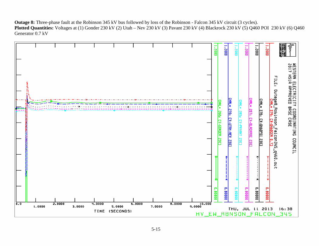
Outage 8: Three-phase fault at the Robinson 345 kV bus followed by loss of the Robinson - Falcon 345 kV circuit (3 cycles). Plotted Quantities: Voltages at (1) Gonder 230 kV (2) Utah – Nev 230 kV (3) Pavant 230 kV (4) Blackrock 230 kV (5) Q460 POI 230 kV (6) Q460 Generator 0.7 kV
5-16
Outage 8: Three-phase fault at the Robinson 345 kV bus followed by loss of the Robinson - Falcon 345 kV circuit (3 cycles). Plotted Quantities: Power on (1) Q460 Generation MW (2) Q460 Generation MVAR (3) Spring Valley Generation MW (4) Spring Valley Generation MVAR
5-17
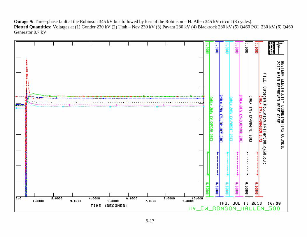
Outage 9: Three-phase fault at the Robinson 345 kV bus followed by loss of the Robinson – H. Allen 345 kV circuit (3 cycles). Plotted Quantities: Voltages at (1) Gonder 230 kV (2) Utah – Nev 230 kV (3) Pavant 230 kV (4) Blackrock 230 kV (5) Q460 POI 230 kV (6) Q460 Generator 0.7 kV
5-18
Outage 9: Three-phase fault at the Robinson 345 kV bus followed by loss of the Robinson – H. Allen 345 kV circuit (3 cycles). Plotted Quantities: Power on (1) Q460 Generation MW (2) Q460 Generation MVAR (3) Spring Valley Generation MW (4) Spring Valley Generation MVAR
5-19
Outage 10: Three-phase fault at the Midpoint 500 kV bus followed by loss of the Midpoint – Hemingway 500 kV circuit (3 cycles). Plotted Quantities: Voltages at (1) Gonder 230 kV (2) Utah – Nev 230 kV (3) Pavant 230 kV (4) Blackrock 230 kV (5) Q460 POI 230 kV (6) Q460 Generator 0.7 kV
5-20
Outage 10: Three-phase fault at the Midpoint 500 kV bus followed by loss of the Midpoint – Hemingway 500 kV circuit (3 cycles). Plotted Quantities: Power on (1) Q460 Generation MW (2) Q460 Generation MVAR (3) Spring Valley Generation MW (4) Spring Valley Generation MVAR
5-21
Outage 11: Single-phase fault at the Holden 46 kV bus followed by delayed clearing with loss of the Holden – Pavant 46 kV circuit (31 cycles). Plotted Quantities: Voltages at (1) Gonder 230 kV (2) Utah – Nev 230 kV (3) Pavant 230 kV (4) Blackrock 230 kV (5) Q460 POI 230 kV (6) Q460 Generator 0.7 kV
5-22
Outage 11: Single-phase fault at the Holden 46 kV bus followed by delayed clearing with loss of the Holden – Pavant 46 kV circuit (31 cycles). Plotted Quantities: Power on (1) Q460 Generation MW (2) Pavant – Blackrock 230 kV line MW (3) Spring Valley Generation MW
5-23
Outage 11: Single-phase fault at the Holden 46 kV bus followed by delayed clearing with loss of the Holden – Pavant 46 kV circuit (31 cycles). Plotted Quantities: MVAR flow on (1) Q460 Generation MVAR (2) Spring Valley Generation MVAR
Please Note: Bus number 64530 (SVSUB230) is known as Oceola Substation.
1. Case: Heavy Load Condition Between Black Rock and Pavant , Path 32 = 235 MW East Bound, Q0460 Online and Spring Valley Generation Online1.1 Base Case: Q460 Online, Path 32 = 235 MW East Bound
Please Note: Bus number 64530 (SVSUB230) is known as Oceola Substation.
1.2 Black Rock to Pavant 230 kV Line Outage
Please Note: Bus number 64530 (SVSUB230) is known as Oceola Substation.
1.3 Black Rock to Pavant 230 kV Line Outage With Delta to McCromick 46 kV Line Open
Please Note: Bus number 64530 (SVSUB230) is known as Oceola Substation.
2.1 Base Case: Q460 Online, Path 32 = 235 MW East Bound2. Case: Heavy Load Condition Between Black Rock and Pavant, Path 32 = 235 MW East Bound, Q0460 Online and Spring Valley Generation Offline
Please Note: Bus number 64530 (SVSUB230) is known as Oceola Substation.
2.2 Black Rock to Pavant 230 kV Line Outage
Please Note: Bus number 64530 (SVSUB230) is known as Oceola Substation.
2.3 Black Rock to Pavant 230 kV Line Outage With Delta to McCormick 46 kV Line Open
Please Note: Bus number 64530 (SVSUB230) is known as Oceola Substation.
3. Case: Light Load Condition Between Black Rock and Pavant, Path 32 = 235 MW East Bound, Q0460 Online and Spring Valley Generation Online
3.1 Base Case: Q460 Online, Path 32 = 235 MW East Bound
Please Note: Bus number 64530 (SVSUB230) is known as Oceola Substation.
3.2 Black Rock to Pavant 230 kV Line Outage
Please Note: Bus number 64530 (SVSUB230) is known as Oceola Substation.
3.3 Black Rock to Pavant 230 kV Line Outage With Delta to McCormick 46 kV Line Open
Please Note: Bus number 64530 (SVSUB230) is known as Oceola Substation.
4. Case: Light Load Condition Between Black Rock and Pavant, Path 32 = 235 MW East Bound, Q0460 Online and Spring Valley Generation Offline4.1 Base Case: Q460 Online, Path 32 = 235 MW East Bound
Please Note: Bus number 64530 (SVSUB230) is known as Oceola Substation.
4.2 Black Rock to Pavant 230 kV Line Outage
Please Note: Bus number 64530 (SVSUB230) is known as Oceola Substation.
4.3 Black Rock to Pavant 230 kV Line Outage With Delta to McCormick 46 kV Line Open
Please Note: Bus number 64530 (SVSUB230) is known as Oceola Substation.
5.1 Present Base Case: Path 32 at 235 MW East Bound
5. Wind Free Technology or Shunt Reactor Case: Light Load Condition Between Black Rock and Pavant, Path 32 = 235 MW East Bound, Spring Valley
Generation Online
Please Note: Bus number 64530 (SVSUB230) is known as Oceola Substation.
5.2 Present Case: Pavant to Sigurd 230 kV Line Outage
Please Note: Bus number 64530 (SVSUB230) is known as Oceola Substation.
5.3. Case: Light Load Condition Between Pavant and Black Rock, Path 32 = 235 MW East Bound, Spring Valley Generation Online and Q0460 Offline
Please Note: Bus number 64530 (SVSUB230) is known as Oceola Substation.
5.4. Pavant to Sigurd 230 kV Line Outage (Wind Farm Collector System Generates 15 MVAr at the Point of Interconnection
Please Note: Bus number 64530 (SVSUB230) is known as Oceola Substation.
5.5. Pavant to Sigurd 230 kV Line Outage, Q0460 Online (No Wind)
Please Note: Bus number 64530 (SVSUB230) is known as Oceola Substation.
5.6. Sigurd to Pavant 230 kV Line Outage, With 15 MVAR Reactor at the Point of Interconnection