Large Matched-Index-of- Refraction (MIR) flow systems for international collaboration in fluid mechanics Donald M. McEligot, University of Idaho, Idaho Falls, Idaho 83402 USA, [email protected]Stefan Becker, iPAT, Universität Erlangen, D-91058 Erlangen, Germany Hugh M. McIlroy, Jr., Idaho National Laboratory (INL), Idaho Falls, Idaho 83415-2200 USA Friedrich-Alexander-Universität Erlangen-Nürmberg
Transcript
Large Matched-Index-of-Refraction (MIR) flow systems for international collaboration in fluid mechanicsDonald M. McEligot, University of Idaho, Idaho Falls, Idaho 83402 USA, [email protected]
Stefan Becker, iPAT, Universität Erlangen, D-91058 Erlangen, Germany
Hugh M. McIlroy, Jr., Idaho National Laboratory (INL), Idaho Falls, Idaho 83415-2200 USA
Friedrich-Alexander-UniversitätErlangen-Nürmberg
210-GA50160-03
Large Matched-Index-of-Refraction (MIR) flow systems for international collaboration in fluid mechanics
Donald M. McEligot, University of Idaho, Idaho Falls, Idaho 83402 USAStefan Becker, iPAT, Uni. Erlangen, D-91058 Erlangen, GermanyHugh M. McIlroy, Jr., Idaho National Laboratory (INL), Idaho Falls, Idaho 83415-2200 USA
Abstract ---- In recent international collaboration, Idaho National Laboratory (INL) and Universität Erlangen (UE) have developed large MIR flow systems which are ideal for joint graduate student education and research. The benefit of the MIR technique is that it permits optical measurements to determine flow characteristics in complex passages and around objects to be obtained without locating a disturbing transducer in the flow field and without distortion of the optical paths. The MIR technique is not new itself; others employed it earlier. The innovation of these MIR systems is their large size relative to previous experiments, yielding improved spatial and temporal resolution. This report will discuss the benefits of the technique, characteristics of the systems and some examples of their applications to complex situations. Typically their experiments have provided new fundamental understanding plus benchmark data for assessment and possible validation of computational thermal fluid dynamic codes.
310-GA50160-03
Topics
• Benefits of refractive-index-matching for optical flow measurements
• Characteristics and advantages of large MIR flow systems
• Some recent international collaboration• Potential collaborative interactions• Concluding remarks
410-GA50160-03
Objective ≈ obtain basic and applied measurements of complicated internal and/or external fluid physics for• Extending fundamental knowledge of generic flow
processes
• Assessment of proposed CFD codes
• Guidance for improving CFD codes, e.g., turbulence models
Technique = optical fluid measurements (LDV, PIV) with transparent models using refractive-index matching
510-GA50160-03
Laser Doppler Velocimetry (LDV)
Fringe model [Rudd, 1969] Signal
Prism-system with fixed beam separation [Durst and Whitelaw, 1971]
610-GA50160-03
3-D Particle Tracking Velocimetry (PTV)[Guezennec, Brodkey, Trigui and Kent, 1994]• Characterize global velocity field in apparatus
• Map path lines of particles
• Deduce mixing of passive scalars (e.g., colloidal particles)
PTV in Annulus Particle Tracking Technique
Camera 1 Camera 2
Measurement volume
710-GA50160-03
Particle Image Velocimetry
The computer then uses a cross correlation technique to generate vector fields and other useful data
Courtesy of LaVision
d ds1
Camera 1 Camera 2
s
α
Object plane
Lens planeImage plane
Light Sheet
z
xy
Cameralens
2-D PIV uses 1 camera and takes planar images
3-D PIV (or stereo) uses 2 cameras to detect particle
motion in all 3 axes of motion
Courtesy of LaVision
Taking Data Data Processing
810-GA50160-03
How does refractive-index-matching help?• Optical techniques avoid disturbing the flow to be measured
• Typical approaches are LDV, PIV, PTV, flow visualization, PLIF, etc.Laser Doppler Velocimetry Particle Image Velocimetry Snell’s Law
• Unless the refractive indices are matched, the view may be distorted or impossible even with "transparent" materials and position measurements may be incorrect
(Rod is resting on the bottom of the beaker)
(Marking is on back of beaker)
Not matched
Matched
Example of application of refractive-index-matching
Refractive index not matched
Plexiglas model
Fluid
Laser beam
Laser beam
Lasertransmissionoptics
Signalcollectionoptics
Internalplexiglasrods
910-GA50160-03
Refractive-Index-Matching
1010-GA50160-03
Example of application of refractive-index-matching
(Rod is resting on the bottom of the beaker)
(Marking is on back of beaker)
Not matched
Matched
1110-GA50160-03
• Advantages– Versatile - basic/applied research, internal / external / coupled flows – Non-intrusive, undistorted measurements of flow and transport– μ-scale to building scale experience– Good spatial and temporal resolution– Benchmark measurements
Apparatus to study fluid physics phenomena in idealized SNF canister for EM Science project
• Most previous MIR experiments have been cm-scale; INL test section is about 0.6 m x 0.6 m x 2.5 m
(Rod is resting on the bottom of the beaker)
(Marking is on back of beaker)
Not matched
Matched
Example of application of refractive-index-matching
Benefits of large MIR flow systems
1210-GA50160-03
The Large INL MIR Flow System
1.452
1.454
1.456
1.458
1.46Mineral Oil - Refractive Index
18 22 26 30 34
n
Temp (°C)20
n = 1.4664 - 0.0003587 T
1310-GA50160-03
MIR Facility Temperature Control
Temperature ControlPC with LabVIEWTM
software
20 Ton Reciprocating Liquid (Glycol) Chiller
(External)
1410-GA50160-03
The large Matched-Index-of-Refraction flow system at Uni. Erlangen
1510-GA50160-03
Technical specifications of the Matched-Index-of-Refraction flow systems
INL Uni. Erlangen Cross section of test section (m2) 0.62 x 0.62 0.6 x 0.45 Length of test section (m) 2.4 2.52 Contraction ratio 4:1 6:1
Fluid / oil Drakeoel 5 (PENRECO)
Odina 913 (SHELL)
LDA index matching temperature (C) 23.75 28.7 Refractive index 1.4579 1.4585 Kinematic viscosity (m2/s) 13.9 x 10⁻⁶ 11.2 x 10⁻⁶ Temperature control External Internal Maximum inlet velocity (m/s) 1.9 5 Inlet turbulence intensity (%) 0.5 - 1 0.15
1610-GA50160-03
Typical recent experiments -- external and internal flows
Realistic rough surfaces in turbomachinery
Idealized SNF canisterBoundary layer transition
CBW agent transport
Venturi Inserts
Flat Plate ModelTurbulence generator
LDV
Flows around buildings
1710-GA50160-03
Some recent international collaboration
Germany, US Structure of transitional flows
Japan, Montenegro, UK, US Coolant flows in advanced GCRs
Germany, US Suction in transitional boundary layers
Korea, Montenegro, UK, US Coolant flows in SCWRs
France, US Flows in the lower plena of GCRs
Germany, Ireland, Sweden, UK, US Entropy generation in transitioning flows
Korea, US Bypass flows in prismatic GCRs
1810-GA50160-03
Transition in boundary layers induced by a square rib –S. Becker and F. Durst, Uni. Erlangen, Germany and K. G. Condie and D. M. McEligot, INL, US Fundamental question = How does the turbulent contribution evolve in a transitional boundary layer?
Becker et al., 2002, Becker et al., 2002, ““LDALDA--Measurements of Transitional Flows Induced by a Square Rib,Measurements of Transitional Flows Induced by a Square Rib,””J. Fluids Eng., J. Fluids Eng., 124124, pp. 108, pp. 108--117117
1910-GA50160-03
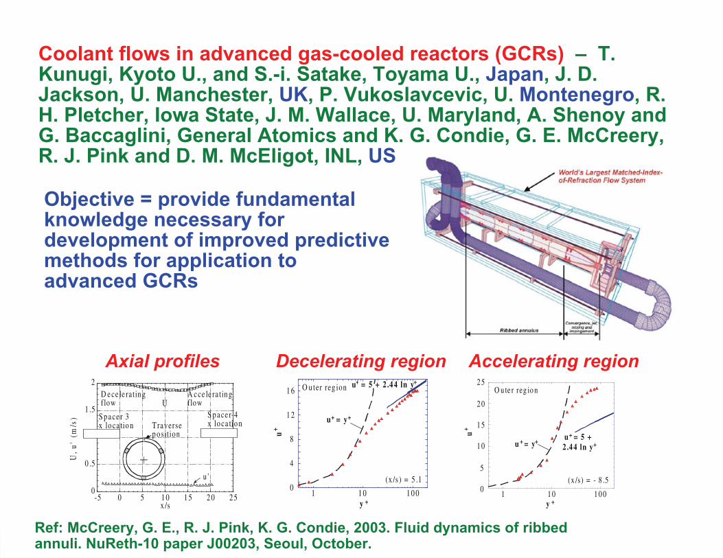
Coolant flows in advanced gas-cooled reactors (GCRs) – T. Kunugi, Kyoto U., and S.-i. Satake, Toyama U., Japan, J. D. Jackson, U. Manchester, UK, P. Vukoslavcevic, U. Montenegro, R. H. Pletcher, Iowa State, J. M. Wallace, U. Maryland, A. Shenoy and G. Baccaglini, General Atomics and K. G. Condie, G. E. McCreery, R. J. Pink and D. M. McEligot, INL, US
Objective = provide fundamental knowledge necessary for development of improved predictive methods for application to advanced GCRs
0
0 .5
1 .5
2
-5 0 5 1 0 1 5 2 0 2 5
U,u
'(m
/s) S p a ce r 3
x lo ca tio nS p a ce r 4x lo ca tio nTraverse
p o sition
u '
A c ce le ratin gflow
D e ce le ratin g flow
x /s
U
Axial profiles Decelerating region Accelerating region
Ref: McCreery, G. E., R. J. Pink, K. G. Condie, 2003. Fluid dynamics of ribbed annuli. NuReth-10 paper J00203, Seoul, October.
0
4
8
1 2
1 6
1 1 0 1 0 0
u+
u+ = y+
y +
(x /s ) = 5 .1
u+ = 5 + 2 .44 ln y+
O u ter reg ion
0
5
1 0
1 5
2 0
2 5
1 1 0 1 0 0
u + = y+
(x /s) = - 8 .5
u = 5 + 2 .44 ln y
++
O u te r reg io n
u+
y +
2010-GA50160-03
Suction in a transitional boundary layer – S. Becker and J. Jovanovic, Uni. Erlangen, Germany and C. M. Stoots, INL, US
Aim = understand the critical parameters affecting stabilization via suction through holes
θ qu
artz
θ ai
r
Velocity and TKE fields 1D behind holes
2110-GA50160-03
Coolant flows in supercritical water reactors – J. Y. Yoo and J. S. Lee, SNU, S. O. Park, KAIST, Korea, J. D. Jackson, U. Manchester, UK, P. Vukoslavcevic, U. Montenegro, L. E. Hochreiter, Penn. State, R. H. Pletcher, Iowa State, B. L. Smith, Utah State, J. M. Wallace, U. Maryland and K. G. Condie, G. E. McCreery, D. M. McEligot, H. M. McIlroy and R.. J. Pink, INL, US
McEligot et al., 2005, “Advanced Computational Thermal Fluid Physics (CTFP) and its Assessment for Light Water Reactors and Supercritical Reactors, “ INEEL/EXT-05-00901, 31 Oct.
Objective = develop fundamental knowledge needed for improved predictive methods in SCWR applications
2210-GA50160-03
Flows in the lower plena of gas-cooled reactors (GCRs) –D. Tenchine, H. Paillere and F. Ducros, CEA, France, H. M. McIlroy, D. M. McEligot and R. J. Pink, INL, R. E. Spall and B. L. Smith, Utah State and W. D. Pointer and C. Tzanos, ANL, US
Large structures
McIlroy, McEligot and Pink, 2010. Nuc. Engr. Design, 240, pp. 416-428.
Objective = provide benchmark data for assessment and improvement of codes proposed for GCRs
2310-GA50160-03
Entropy generation in transitioning flows – D. M. McEligot, R. S. Budwig and A. Tokuhiro, U. Idaho, H. M. McIlroy, INL, J. R. Ferguson, Boise State, US, S. Becker, Uni. Erlangen, Germany, E. J. Walsh, U. Limerick, Ireland, L. Brandt and P. Schlatter, KTH, Sweden and T. A. Zaki, Imperial College, UK
Separated flow behind rib
Objective = obtain basic understanding of local (pointwise) distributions of entropy generation rates in characteristic wall shear flows (Sap''')* = (TSap'''δ/(ρU∞
3))
-0.001 0 0.001 0.002 0.003 0.004 0.0050
1
2
3
4
5
6
(Sap
''') *
y/k
Rek = 358
(x-x
k) / k = 4, 9.3 and 23.8
Volumetric entropy generation rate
Rek = 502
0 0.005 0.01 0.015 0.02 0.0250.1
1
(Sap
''') *
y/k
Ba-S+log-plt2
x* = 38.3 - 262
Volumetric entropy generation rate
Rek = 358
6
0 0.005 0.01 0.015 0.02 0.0250.1
1
(Sap
''') *
y/k
Bc-S+log-plt2
x* = 38.3 - 111
Volumetric entropy generation rate
Rek = 502
6
Laminar recovery Transitioning boundary layer
2410-GA50160-03
Bypass flows in prismatic GCRs – G.-C. Park, SNU, and M.-H. Kim, KAERI, Korea, H. M. McIlroy and R. R. Schultz, INL, US Objectives = understanding bypass flows and developing improved estimates of associated loss coefficients and surface friction for normal power, reduced power and residual heat removal
Hemisphere
Coolant ChannelsRech~ 6000
Inlet Annulus
Upper Plenum
LowerFuel Block
Upper Fuel Block
2510-GA50160-03
Potential collaborative interactions
• Faculty projects in fluid mechanics areas of mutual interest• Faculty collaborative research proposals • Faculty sabbatical leaves• Doctoral dissertations and masters theses• Training students by participation in ongoing experiments• Training post doctoral associates• Fluid mechanics conferences and workshops on topical
areas of interest• Modifications of facilities to expand capabilities of interest• Advisory committees and review panels
2610-GA50160-03
Concluding remarks
• The U. Erlangen and INL MIR systems are versatile, useful tools for examining flows in complicated situations
• Benchmark data can be acquired for external, internal and coupled flows
• They are excellent bases for interesting international collaboration in graduate education
Further detailsMcEligot, Becker and McIlroy, ICEE-2010 ProceedingsMcEligot, Becker and McIlroy, 2010. Tech. rpt. INL/EXT-10-18835.Internet site = www.inl.gov/mir