34
AILU 08, Daresbury Laboratory, June 2008 Guido Hennig, Karl - Heinz Selbmann, Stephan Brüning, Silke Pfinninger, Johannes Brendel Large Scale Laser Microstructuring of Gravure Printforms

AILU 08, Daresbury Laboratory, June 2008
Guido Hennig, Karl - Heinz Selbmann, Stephan Brüning, Silke Pfinninger, Johannes Brendel
Large Scale Laser Microstructuring of Gravure Printforms
TopicsLasers in the printing industry
1. Introduction to Gravure printing
2. Gravure print form fabrication at MDC Max Daetwyler Group
- Mask Ablation- Direct Laser Engraving
3. Flexible cell shape / benefits
- Adaptable Beam Profile for different print media (different print substrates, magazines, packaging, embossing)
4. Requirements for the gravure process, determining laser parameters and material
- Processing Time- Precision (Zn vs. Cu)
5. New methods- New Laser Sources and Engraving concepts
6. Outlook - Laser in Print applications – the Future

Overview #11. Print processes with laser fabrication of the print form
European Printing Market
Offset Printing 42% Screen Printing 2%
Others: Plateless, Inkjet 17%
Gravure Printing 16%
Steel Roller + Cu/Cr or Zn/Cr surface Layer
Gravure Cylinder
Ink
Doctor blade
Substrate
Impression roller
Flexography 23%

105 < # Runs < 8x10⁶
European Printing Market
Offset Printing 42% Screen Printing 2%
Others: Plateless, Inkjet 17%
Gravure Printing 16%
Steel Roller + Cu/Cr or Zn/Cr surface Layer
1. Printprocesses using laser microfabrication Overview #2
Flexography 23%
103< # Runs <105 10 < # Runs <104102 < # Runs < 106
(Nassofset)Al(oxide) Offset Plate, Silicon rubber coated
Flexography sleeve, plate
Metallic or textile web,plate,sleeve
Electro-plated Sleeve
Examples: Cups, Textiles, T-shirt, electronic prints
overview2. Gravure - Fabrication of the printform
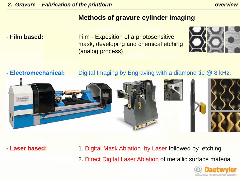
Methods of gravure cylinder imaging
- Film based: Film - Exposition of a photosensitivemask, developing and chemical etching(analog process)
- Electromechanical: Digital Imaging by Engraving with a diamond tip @ 8 kHz.
- Laser based: 1. Digital Mask Ablation by Laser followed by etching
2. Direct Digital Laser Ablation of metallic surface material
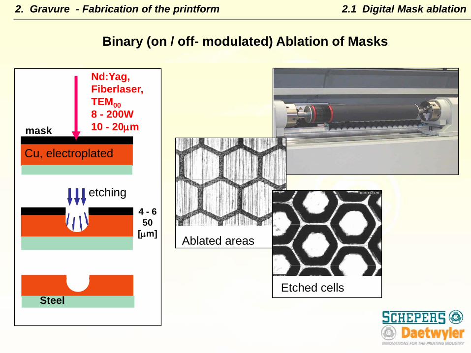
Binary (on / off- modulated) Ablation of Masks
Cu, electroplated
Nd:Yag,Fiberlaser, TEM008 - 200W10 - 20µm
etching
Steel
mask
4 - 650
[µm]Ablated areas
Etched cells
2.1 Digital Mask ablation2. Gravure - Fabrication of the printform
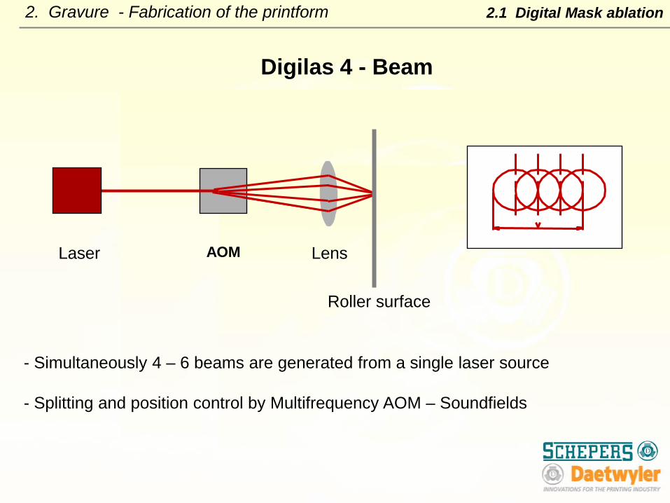
- Simultaneously 4 – 6 beams are generated from a single laser source
- Splitting and position control by Multifrequency AOM – Soundfields
Digilas 4 - Beam
Laser AOM Lens
Roller surface
2. Gravure - Fabrication of the printform 2.1 Digital Mask ablation

2. Gravure - Fabrication of the printform 2.1 Digital Mask ablation
Multiple 4 beams
Lasertraces
Ablated areas of the mask
Print roller
Etchingresults
Multifrequency AOM – Soundfields
1. Screen adjustment 2. Position and power for each shot of a pulse string
are programmable within modulator rise time
binary on / off modulated
BILD!!
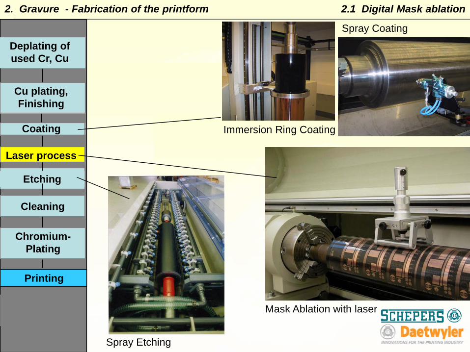
Process steps
Mask Ablation with laser
Spray Coating
Spray Etching
Immersion Ring Coating
Printing
2.1 Digital Mask ablation
Deplating of used Cr, Cu
Cu plating, Finishing
Chromium-Plating
Cleaning
Laser process
Coating
Etching
2. Gravure - Fabrication of the printform

Testpattern for printed electronics:
FET structures
Substrate: polymer foil or glas
Conducting ink (silver particles) (SIGPA)
2.1 Gravure - digital mask ablation 2.1.1 Printed electronics

2.2 Direct Laser Ablation
Q-switch Nd-Yag70kHz,
Fiber Optics
Focusing Optics
Cylinder
Laser AOM
Image Data
2x 35 kHz
DIRECT ENGRAVING OF METALLIC SURFACES
Melting and vaporisation
500 W
2. Gravure - Fabrication of the printform
1 pulse 1 cell
2.2 Direct Laser Ablation
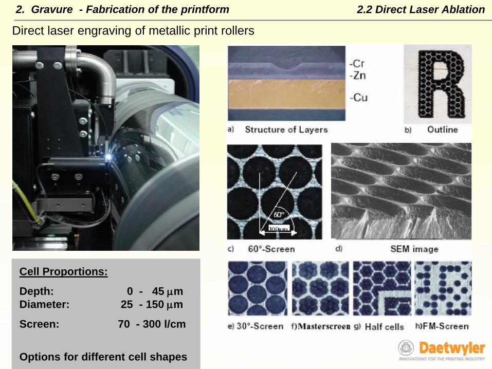
Direct laser engraving of metallic print rollers
Cell Proportions:
Depth: 0 - 45 µmDiameter: 25 - 150 µm
Screen: 70 - 300 l/cm
Options for different cell shapes
2. Gravure - Fabrication of the printform
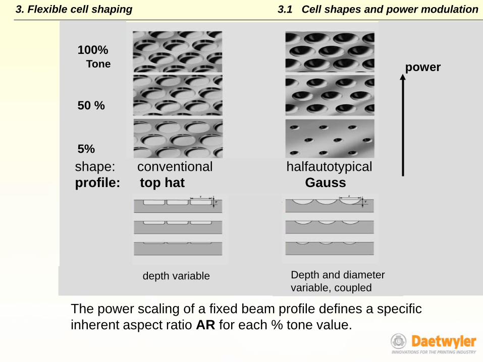
The power scaling of a fixed beam profile defines a specific inherent aspect ratio AR for each % tone value.
3.1 Cell shapes and power modulation
depth variable
100%
50 %
5%
power
Depth and diameter variable, coupled
Tone
shape: conventional halfautotypicalprofile: top hat Gauss
3. Flexible cell shaping

Conditions for optimised ink transfer 0.1 < AR < 0.5 for low quality substrates
0.05 < AR < 0.5 for high quality substrates
AR = depth/diameter
3.2 Ink transfer and AR
Independent control of depth and diameter
3. Flexible cell shaping
AR > 0,5 AR < 0.05
- ink dries before substrate contact
- unstable ink transfer- missing dots- doughnut print
- no ink transferbecause ofcapillary forces
30 µm
2 µm
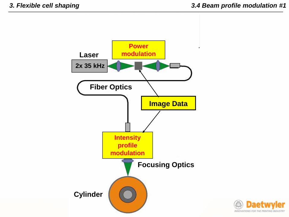
3.4 Beam profile modulation #1
Fiber Optics
Focusing Optics
Cylinder
Laser AOM
Image Data
2x 35 kHz
Intensity profile
modulation
Power modulation
3. Flexible cell shaping
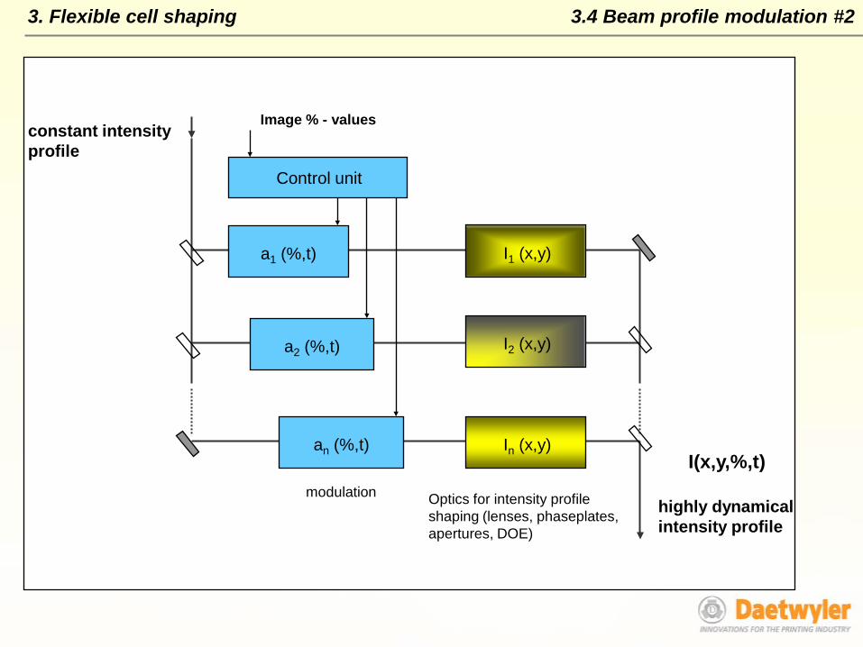
a1 (%,t)
In (x,y)an (%,t)
a2 (%,t) I2 (x,y)
I1 (x,y)
Control unit
constant intensityprofile
highly dynamicalintensity profile
Image % - values
modulation Optics for intensity profile shaping (lenses, phaseplates, apertures, DOE)
I(x,y,%,t)
3. Flexible cell shaping 3.4 Beam profile modulation #2
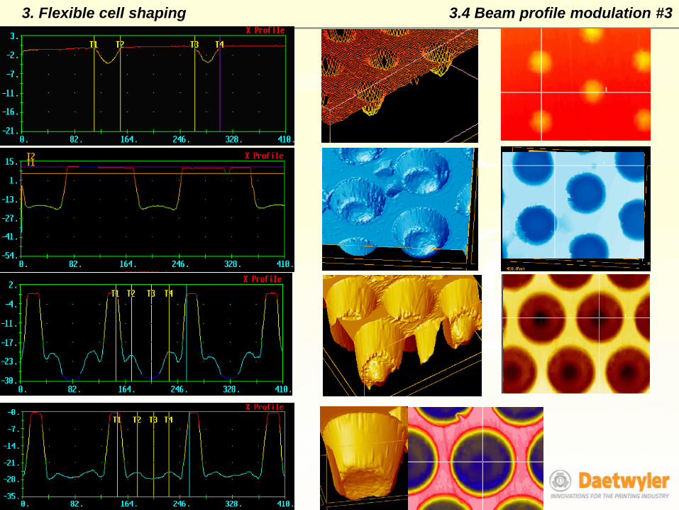
3. Flexible cell shaping 3.4 Beam profile modulation #3
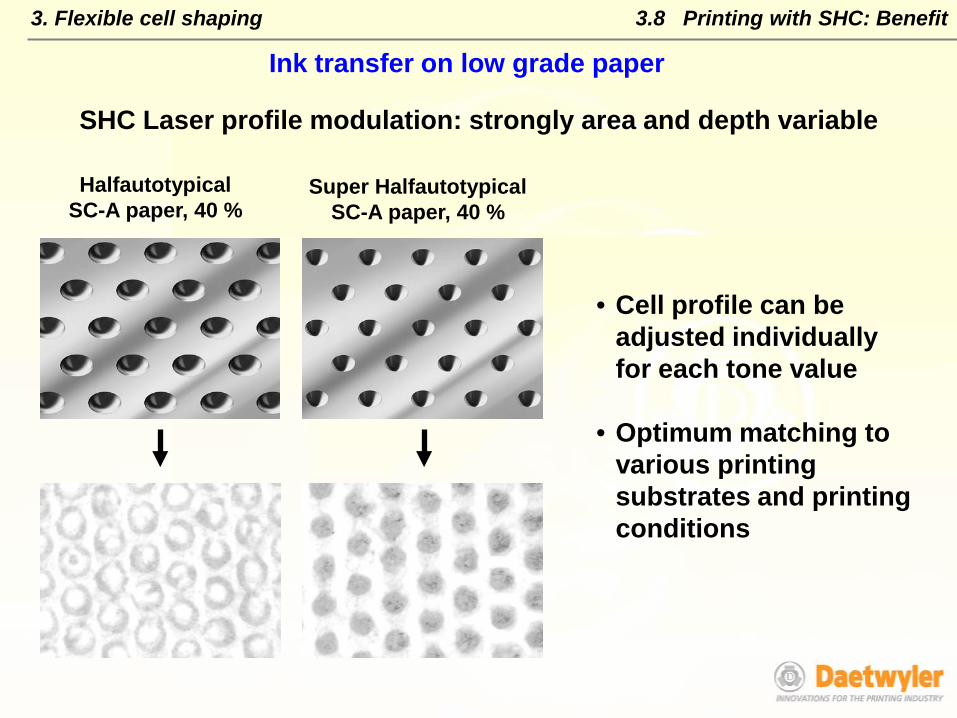
3.8 Printing with SHC: Benefit
• Cell profile can be adjusted individually for each tone value
• Optimum matching to various printing substrates and printing conditions
HalfautotypicalSC-A paper, 40 %
Super HalfautotypicalSC-A paper, 40 %
SHC Laser profile modulation: strongly area and depth variable
Ink transfer on low grade paper
3. Flexible cell shaping
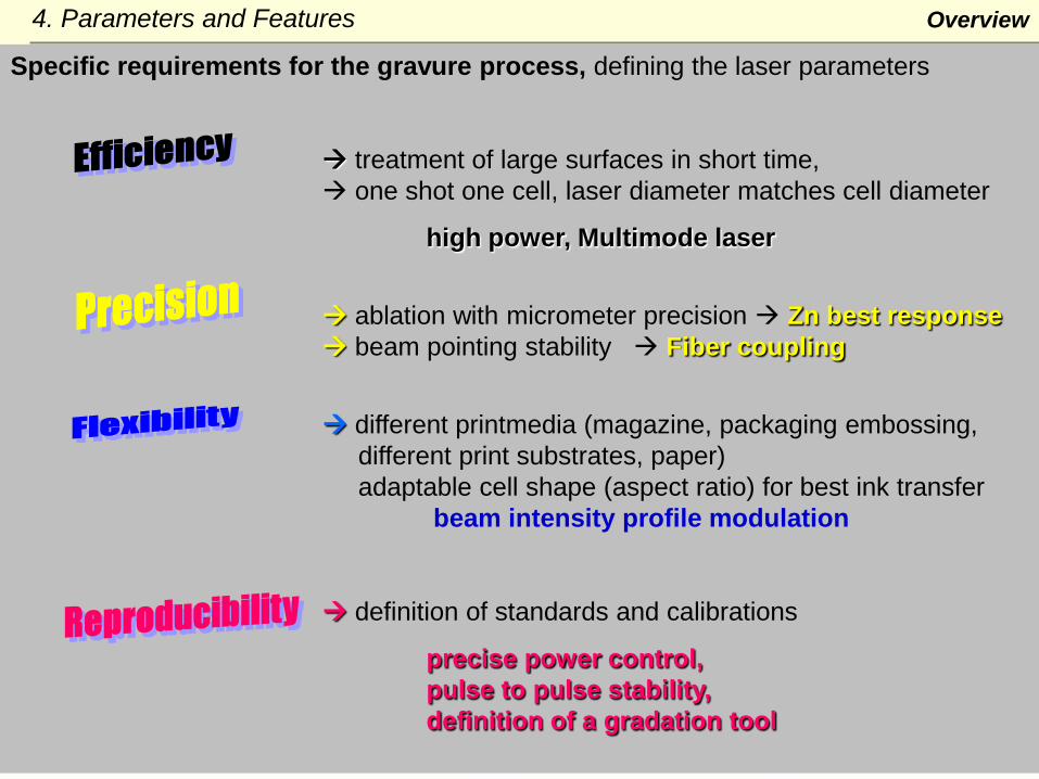
Overview4. Parameters and Features
Specific requirements for the gravure process, defining the laser parameters
treatment of large surfaces in short time, one shot one cell, laser diameter matches cell diameter
high power, Multimode laser
ablation with micrometer precision Zn best response beam pointing stability Fiber coupling
different printmedia (magazine, packaging embossing, different print substrates, paper)adaptable cell shape (aspect ratio) for best ink transfer
beam intensity profile modulation
definition of standards and calibrations
precise power control, pulse to pulse stability,definition of a gradation tool

4.1 Treatment of large surfaces4. Parameters
High Power Multimode Laser:
2x Nd:YAG 1064 nm, 400 W 35 kHz Q – switch, 10 mJ
Engraving Head:
Power 500 WPulse Frequency 70.000 cells /s
single shotEngraving @ 70l/cm: 11.6 Min / m2
Engraving Time / m2
050
100150200250300350400
0 100 200 300 400 500
screen [L/cm]
min
high resolution screens
low resolution
EM Laser

Printing CharacteristicSmoother Print with DLS cylinders
Direct Laser@ 120 l/cm
Much smoother print due to finer dots/ higher resolution
Stylus Engraving@ 70 l/cm
4. Parameters
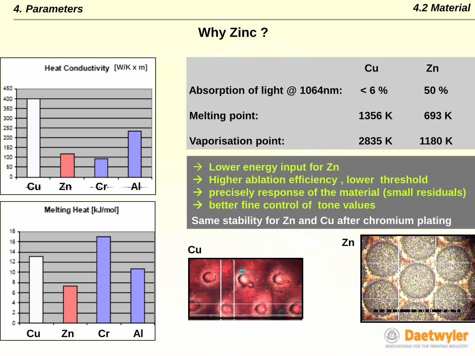
Same stability for Zn and Cu after chromium plating
Lower energy input for Zn Higher ablation efficiency , lower threshold precisely response of the material (small residuals) better fine control of tone values
4.2 Material
Cu Zn
Absorption of light @ 1064nm: < 6 % 50 %
Melting point: 1356 K 693 K
Vaporisation point: 2835 K 1180 K
ZnCu
[W/K x m]
Cu Zn Cr Al
Cu Zn Cr Al
Why Zinc ?
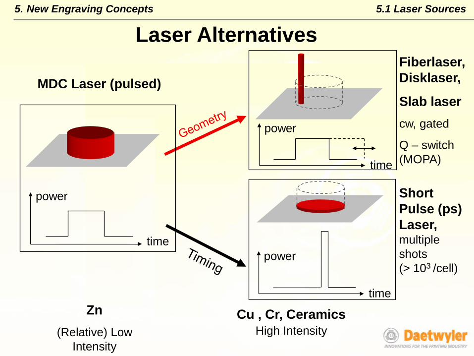
Laser Alternatives
Zn(Relative) Low
Intensity
Cu , Cr, CeramicsHigh Intensity
Fiberlaser, Disklaser,
Slab lasercw, gated
Q – switch (MOPA)
Short Pulse (ps) Laser,multipleshots(> 103 /cell)
MDC Laser (pulsed)
time
power
time
power
time
power
5. New Engraving Concepts 5.1 Laser Sources
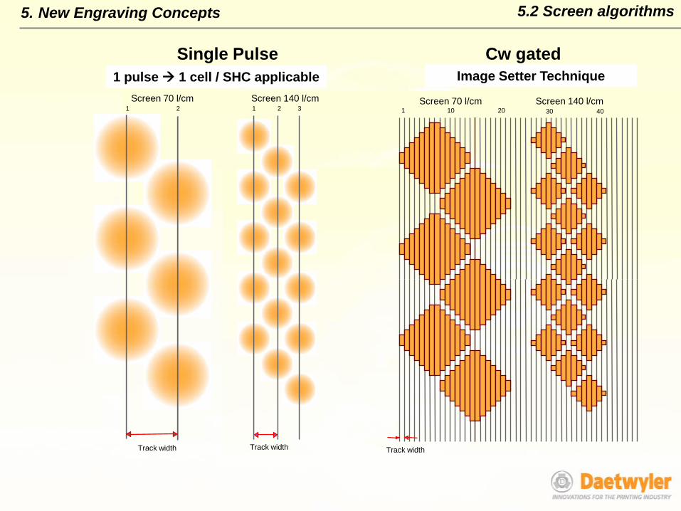
Track width
One Shot - One Cell
Screen 70 l/cm Screen 140 l/cm
Track width
1 2 31 2
Single Pulse1 pulse 1 cell / SHC applicable
1 10 20 40
Image Setter Technique
Screen 70 l/cm Screen 140 l/cm
Track width
30
Cw gatedImage Setter Technique
5.2 Screen algorithms5. New Engraving Concepts

5. New Engraving Concepts
Engraving of metals, cw – Fiber laser @ 600 W, M 2 = 1.2
Cu
Zn
Image Setter Technique: Resolution 1000 l/cm
5.2 Screen algorithms: cw – fiberlaser # 1
100 µm
100 µm
5.2 Screen algorithms: cw – fiberlaser # 25. New Engraving Concepts
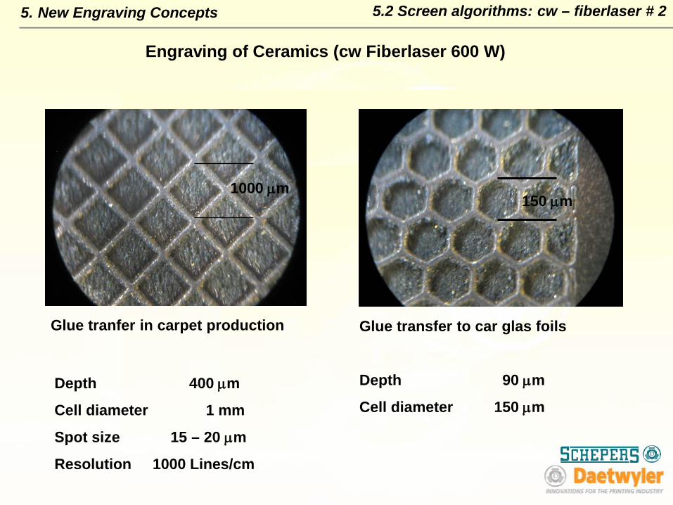
Engraving of Ceramics (cw Fiberlaser 600 W)
1000 µm150 µm
Glue tranfer in carpet production Glue transfer to car glas foils
Depth 90 µm
Cell diameter 150 µmDepth 400 µm
Cell diameter 1 mm
Spot size 15 – 20 µm
Resolution 1000 Lines/cm
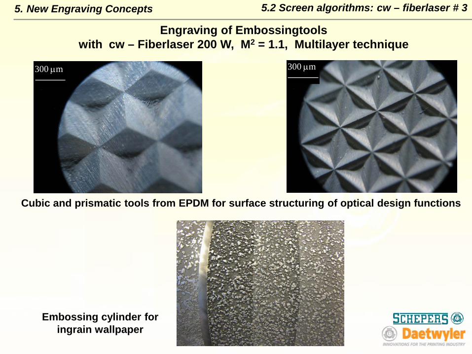
Engraving of Embossingtoolswith cw – Fiberlaser 200 W, M2 = 1.1, Multilayer technique
5. New Engraving Concepts 5.2 Screen algorithms: cw – fiberlaser # 3
Cubic and prismatic tools from EPDM for surface structuring of optical design functions
Embossing cylinder for ingrain wallpaper
300 µm 300 µm
Summary Lasers gravure industry: - LPSSL, DPSSL, fiber lasers
Advantages of direct laser engraving - efficiency, resolution, precisionvs. EM
The flexible beam profile modulation - optimisation of the cell shape - optimised ink transfer - economical printing.
OutlookFiberlasers are already common for mask ablation and started to enter the direct ablation processes and Laser Systems in Gravure and Embossing.(cw - and MOPA Systems)
Ultrashort pulse Systems are options for the future, if the power matches the requirements for efficiency and the costs are drastically reduced.
The ability for big ink volumes enables new applications with special pigments and special materials (for example printing of RFID, electronic circuits or displays)
5. Outlook

Deplating of chromium and Zinc
Degreasing and polishing
Zinc plating 60 µm
Surface fine polishing
Laser engraving
Cleaning and polishing
Chrome plating
Chrome polishing
Cylinder from the press
Cylinder ready to print
Cylinder Workflow # 1Appendix
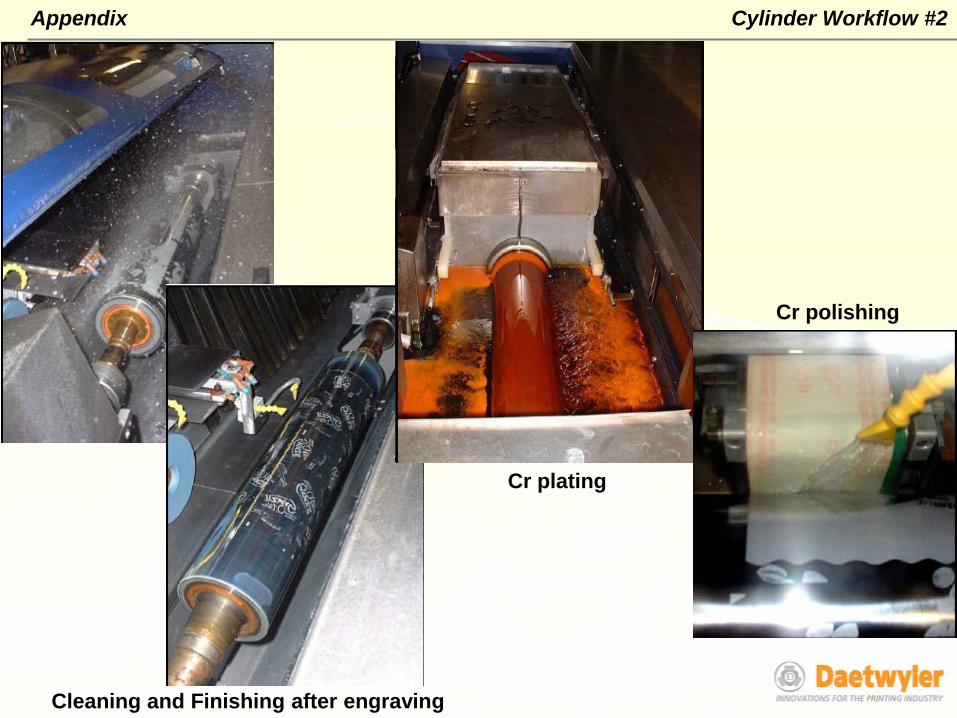
Cleaning and Finishing after engraving
Cr polishing
Cr plating
Appendix Cylinder Workflow #2
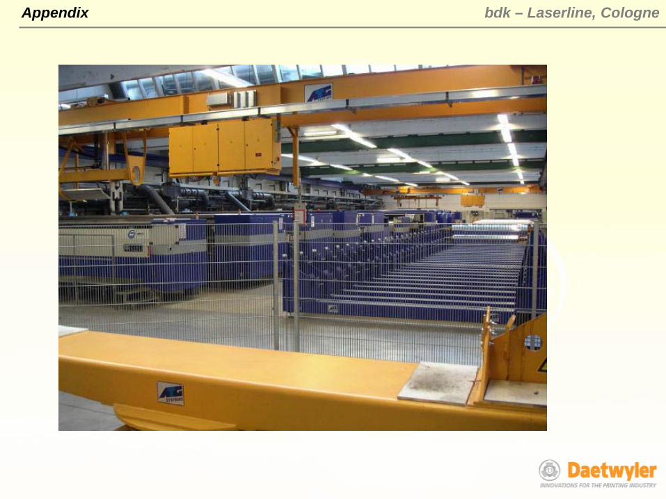
bdk – Laserline, CologneAppendix

Saueressig - production line, GermanyAppendix.

Thank you for your attention!
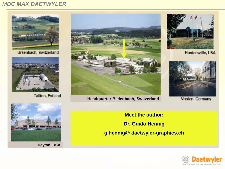
MDC MAX DAETWYLER
Dayton, USA
Meet the author:
Dr. Guido Hennig
g.hennig@ daetwyler-graphics.ch
Headquarter Bleienbach, Switzerland


