Laser beam shaping for biomedical microscopy techniques Alexander Laskin a , Peter Kaiser b , Vadim Laskin a , Aleksei Ostrun c a AdlOptica GmbH, Rudower Chaussee 29, 12489 Berlin, Germany b Visitron Systems GmbH, Gutenbergstrasse 9, 82178 Puchheim, Germany c St. Petersburg National Research University of Information Technologies, Mechanics and Optics, Kronverkskiy pr, 49, 197101, St.Petersburg, Russia ABSTRACT Uniform illumination of a working field is very important in optical systems of confocal microscopy and various implementations of fluorescence microscopy like TIR, SSIM, STORM, PALM to enhance performance of these laser- based research techniques. Widely used TEM 00 laser sources are characterized by essentially non-uniform Gaussian intensity profile which leads usually to non-uniform intensity distribution in a microscope working field or in a field of microlenses array of a confocal microscope optical system, this non-uniform illumination results in instability of measuring procedure and reducing precision of quantitative measurements. Therefore transformation of typical Gaussian distribution of a TEM 00 laser to flat-top (top hat) profile is an actual technical task, it is solved by applying beam shaping optics. Due to high demands to optical image quality the mentioned techniques have specific requirements to a uniform laser beam: flatness of phase front and extended depth of field, - from this point of view the microscopy techniques are similar to holography and interferometry. There are different refractive and diffractive beam shaping approaches used in laser industrial and scientific applications, but only few of them are capable to fulfil the optimum conditions for beam quality required in discussed microscopy techniques. We suggest applying refractive field mapping beam shapers Shaper, which operational principle presumes almost lossless transformation of Gaussian to flat-top beam with flatness of output wavefront, conserving of beam consistency, providing collimated low divergent output beam, high transmittance, extended depth of field, negligible wave aberration, and achromatic design provides capability to work with several lasers with different wavelengths simultaneously. The main function of a beam shaper is transformation of laser intensity profile, further beam transformation to provide optimum for a particular technique spot size and shape has to be realized by an imaging optical system which can include microscope objectives and tube lenses. This paper will describe design basics of refractive beam shapers and optical layouts of their applying in microscopy systems. Examples of real implementations and experimental results will be presented as well. Keywords: confocal microscopy, fluorescence microscopy, laser, beam shaping, flat-top, tophat, homogenizing. 1. INTRODUCTION Lasers are widely used in modern microscopy and make possible realization of various fluorescence techniques and high resolution imaging of samples. Typically the intensity distribution of laser sources is described by Gaussian function provided by physics of creating the laser radiation. This Gaussian profile is naturally inhomogeneous, and this inhomogeneity of intensity is rather a source of problems in microscopy: variation of intensity of working field and brightness of reproduced images, instability of image capturing processes, reduced image contrast, inconvenience in realization of optical setups. It is possible to speak about two basic tasks of uniform illumination: in an objective field [1] and on array of microlenses on spinning disk in optical systems of confocal microscopes [2]. In both considered cases, the light beam has to be collimated, i.e. flatness of both phase front and intensity distribution should be realized simultaneously. There are several beam shaping techniques applied in modern laser technologies, some of them, like
Transcript
Laser beam shaping for biomedical microscopy techniques
Alexander Laskina, Peter Kaiserb, Vadim Laskina, Aleksei Ostrunc
a AdlOptica GmbH, Rudower Chaussee 29, 12489 Berlin, Germany b Visitron Systems GmbH, Gutenbergstrasse 9, 82178 Puchheim, Germany c St. Petersburg National Research University of Information Technologies,
Mechanics and Optics, Kronverkskiy pr, 49, 197101, St.Petersburg, Russia
ABSTRACT
Uniform illumination of a working field is very important in optical systems of confocal microscopy and various implementations of fluorescence microscopy like TIR, SSIM, STORM, PALM to enhance performance of these laser-based research techniques. Widely used TEM00 laser sources are characterized by essentially non-uniform Gaussian intensity profile which leads usually to non-uniform intensity distribution in a microscope working field or in a field of microlenses array of a confocal microscope optical system, this non-uniform illumination results in instability of measuring procedure and reducing precision of quantitative measurements. Therefore transformation of typical Gaussian distribution of a TEM00 laser to flat-top (top hat) profile is an actual technical task, it is solved by applying beam shaping optics. Due to high demands to optical image quality the mentioned techniques have specific requirements to a uniform laser beam: flatness of phase front and extended depth of field, - from this point of view the microscopy techniques are similar to holography and interferometry. There are different refractive and diffractive beam shaping approaches used in laser industrial and scientific applications, but only few of them are capable to fulfil the optimum conditions for beam quality required in discussed microscopy techniques. We suggest applying refractive field mapping beam shapers
Shaper, which operational principle presumes almost lossless transformation of Gaussian to flat-top beam with flatness
of output wavefront, conserving of beam consistency, providing collimated low divergent output beam, high transmittance, extended depth of field, negligible wave aberration, and achromatic design provides capability to work with several lasers with different wavelengths simultaneously. The main function of a beam shaper is transformation of laser intensity profile, further beam transformation to provide optimum for a particular technique spot size and shape has to be realized by an imaging optical system which can include microscope objectives and tube lenses.
This paper will describe design basics of refractive beam shapers and optical layouts of their applying in microscopy systems. Examples of real implementations and experimental results will be presented as well.
1. INTRODUCTION Lasers are widely used in modern microscopy and make possible realization of various fluorescence techniques and high
resolution imaging of samples. Typically the intensity distribution of laser sources is described by Gaussian function
provided by physics of creating the laser radiation. This Gaussian profile is naturally inhomogeneous, and this
inhomogeneity of intensity is rather a source of problems in microscopy: variation of intensity of working field and
brightness of reproduced images, instability of image capturing processes, reduced image contrast, inconvenience in
realization of optical setups. It is possible to speak about two basic tasks of uniform illumination: in an objective field [1]
and on array of microlenses on spinning disk in optical systems of confocal microscopes [2]. In both considered cases,
the light beam has to be collimated, i.e. flatness of both phase front and intensity distribution should be realized
simultaneously. There are several beam shaping techniques applied in modern laser technologies, some of them, like
integration systems based on arrays of microlenses, micromirrors, prisms, cannot be applied since their physical principle
implies destroying the beam structure and, hence, leads to loss of spatial coherence. Other techniques: truncation of a
beam by an aperture, attenuation by apodizing filters allow obtaining acceptable in many cases homogeneity of intensity
profile, but evident disadvantage of these techniques is essential loss of costly laser energy. To meet the demands of
modern microscopy it is suggested to apply beam shaping systems built on the base of field mapping refractive beam
shapers like Shaper, which operational principle implies almost lossless transformation of laser intensity distribution
from Gaussian to flat-top, conserving of beam consistency, flatness of output phase front, low divergence of collimated
output beam, high transmittance, extended depth of field, capability to operate with TEM00 or multimode lasers,
implementations as telescopes or collimators. This article describes basic principles and important features of refractive
beam shapers as well as some optical layouts that can be built on their base to meet requirements of modern microscopy
techniques.
2. FIELD MAPPING REFRACTIVE BEAM SHAPERS
2.1 Basics of optical design
The design principles of refractive beam shapers of field
mapping type, like Shaper, are well-known and
described in the literature3-9. Most often these devices
are implemented as telescopic systems with two optical
components, it is implied that wave fronts at input and
output are flat, the transformation of intensity profile
from Gaussian to uniform is realized in a controlled
manner, by accurate introducing of wave aberration by
the first component and further its compensation by the
second one, Fig.1, top. Thus, the resulting collimated
output beam has uniform intensity and flat wave front; it
is characterized by low divergence – almost the same
like one of the input beam. In other words, the field
mappers transform the intensity distribution without
deterioration of the beam consistency and without
increasing of beam divergence.
Shortly the main features of refractive field mappers are:
- refractive optical systems transforming Gaussian
to flat-top (uniform) intensity distribution;
- transformation through controlled phase front
manipulation – 1st component introduces spherical
aberration required to re-distribute the energy,
then 2nd component compensates the aberration;
- output beam is free of aberrations, phase profile is
maintained flat, hence, low output divergence;
- TEM00 and multimode beams applied;
- collimated output beam;
- resulting beam profile is stable over large distance;
- implementations as telescopic or collimating
optical systems;
Figure 1 Refractive field mapping beam shaper Shaper
Figure 2. Experimental intensity profiles: Left – Input TEM00 beam, Right - after the Shaper
- achromatic optical design, hence the beam shaping is provided for a certain spectral range and makes it possible to
apply several different lasers simultaneously;
- Galilean design, no internal focusing.
Example of beam shaping for Nd:YAG laser is presented in Fig.2.
2.2 Propagation of flat-top beams in space
It is usual to characterize beam shaping optics by the working distance – the distance from last optical component to a
plane where a target intensity profile, flat-top or another one, is created. The working distance is an important
specification for diffractive beam shapers and refractive homogenizers (or integrators) based on multi lens arrays. But in
case of the field mapping beam shapers the output beam is collimated and, hence, instead of a definite plane where a
resulting intensity profile is created, there exists certain space after a beam shaper where the profile is kept stable. In
other words, the working distance isn’t a specification for the field mapping beam shapers, it is better to specify the
depth of field (DOF) after a beam shaper where resulting intensity profile is stable. This DOF is defined by diffraction
effects happening while a beam propagating and depends on wavelength and beam size.
When a TEM00 laser beam with Gaussian intensity distribution propagates in space its size varies due to inherent beam
divergence but the intensity distribution stays stable, this is a famous feature of TEM00 beams that is widely used in
practice. But this brilliant feature is valid for Gaussian beams only! When light beams with non-Gaussian intensity
distributions, for example flat-top beams, propagate in space, they get simultaneously variation of both size and
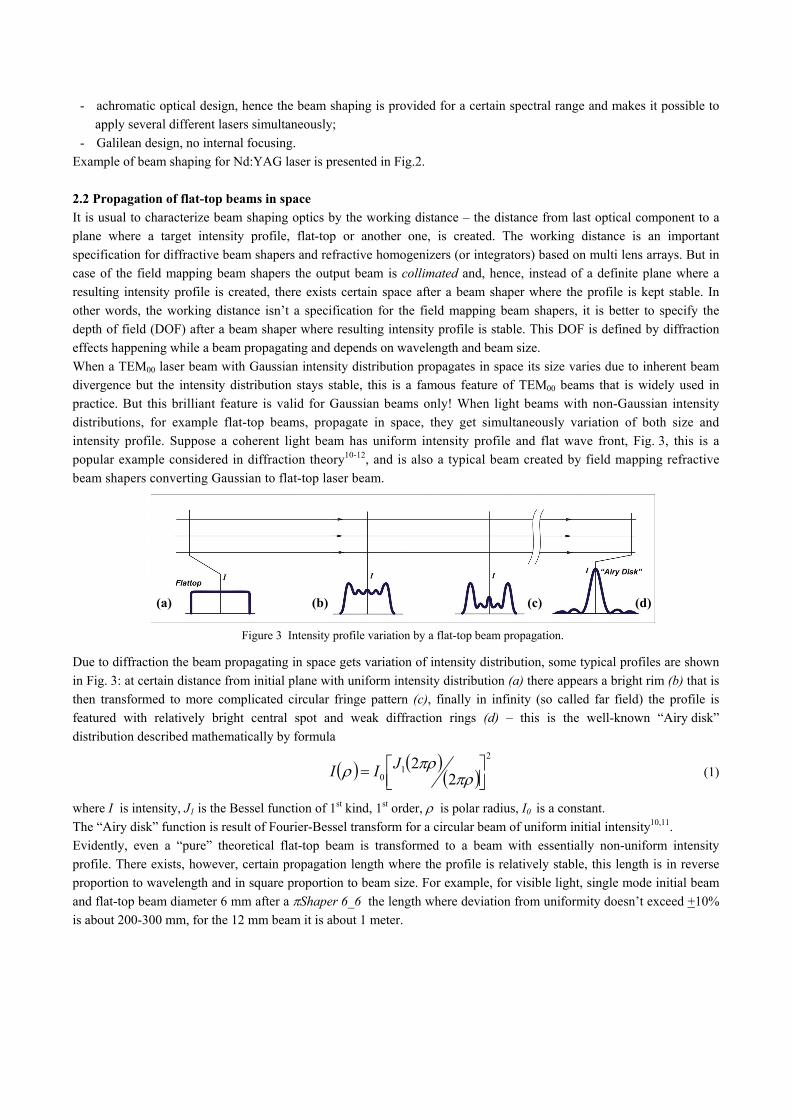
intensity profile. Suppose a coherent light beam has uniform intensity profile and flat wave front, Fig. 3, this is a
popular example considered in diffraction theory10-12, and is also a typical beam created by field mapping refractive
beam shapers converting Gaussian to flat-top laser beam.
Figure 3 Intensity profile variation by a flat-top beam propagation.
Due to diffraction the beam propagating in space gets variation of intensity distribution, some typical profiles are shown
in Fig. 3: at certain distance from initial plane with uniform intensity distribution (a) there appears a bright rim (b) that is
then transformed to more complicated circular fringe pattern (c), finally in infinity (so called far field) the profile is
featured with relatively bright central spot and weak diffraction rings (d) – this is the well-known “Airy disk”
distribution described mathematically by formula
2
10 2
2
JII (1)
where I is intensity, J1 is the Bessel function of 1st kind, 1st order, is polar radius, I0 is a constant.
The “Airy disk” function is result of Fourier-Bessel transform for a circular beam of uniform initial intensity10,11.
Evidently, even a “pure” theoretical flat-top beam is transformed to a beam with essentially non-uniform intensity
profile. There exists, however, certain propagation length where the profile is relatively stable, this length is in reverse
proportion to wavelength and in square proportion to beam size. For example, for visible light, single mode initial beam
and flat-top beam diameter 6 mm after a Shaper 6_6 the length where deviation from uniformity doesn’t exceed +10%
is about 200-300 mm, for the 12 mm beam it is about 1 meter.
(a) (b) (c) (d)
There are many laser applications where conserving a uniform intensity profile over certain distance is required, for
example illumination of array of microlenses on a spinning disk in optical system of confocal microscopes; the extended
DOF is also very important to provide less tough tolerances on positioning of components of optical path. As a solution
to the task of providing a necessary resulting spot size with conserving the flat-top profile over extended DOF it is
fruitful to apply imaging techniques that are considered in next chapter.
3. IMAGING OF FLAT-TOP BEAMS
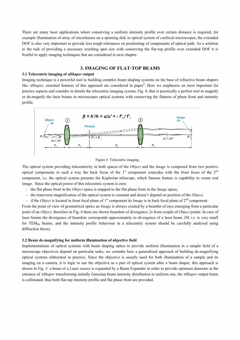
3.1 Telecentric imaging of Shaper output
Imaging technique is a powerful tool to building complex beam shaping systems on the base of refractive beam shapers
like Shaper, essential features of this approach are considered in paper9. Here we emphasize on most important for
practice aspects and consider in details the telecentric imaging system, Fig. 4, that is practically a perfect tool to magnify
or de-magnify the laser beams in microscopes optical systems with conserving the flatness of phase front and intensity
profile.
Figure 4 Telecentric imaging.
The optical system providing telecentricity in both spaces of the Object and the Image is composed from two positive
optical components in such a way the back focus of the 1st component coincides with the front focus of the 2nd
component, i.e. the optical system presents the Keplerian telescope, which famous feature is capability to create real
image. Since the optical power of this telecentric system is zero:
- the flat phase front in the Object space is mapped to the flat phase front in the Image space,
- the transverse magnification of the optical system is constant and doesn’t depend on position of the Object,
- if the Object is located in front focal plane of 1st component its Image is in back focal plane of 2nd component.
From the point of view of geometrical optics an Image is always created by a beamlet of rays emerging from a particular
point of an Object, therefore in Fig. 4 there are shown beamlets of divergence 2u from couple of Object points. In case of
laser beams the divergence of beamlets corresponds approximately to divergence of a laser beam 2, i.e. is very small
for TEM00 beams, and the intensity profile behaviour in a telecentric system should be carefully analysed using
diffraction theory.
3.2 Beam de-magnifying for uniform illumination of objective field
Implementations of optical systems with beam shaping optics to provide uniform illumination in a sample field of a
microscope objectives depend on particular tasks, we consider here a generalized approach of building de-magnifying
optical systems elaborated in practice. Since the objective is usually used for both illumination of a sample and its
imaging on a camera, it is logic to use the objective as a part of optical system after a beam shaper, this approach is
shown in Fig. 5: a beam of a Laser source is expanded by a Beam Expander in order to provide optimum diameter at the
entrance of Shaper transforming initially Gaussian beam intensity distribution to uniform one, the Shaper output beam
is collimated, thus both flat-top intensity profile and flat phase front are provided.
Figure 5 Layout to uniform illumination of microscope field.
The sample has to be illuminated by uniform collimated beam therefore a discussed in subsection 3.1 de-magnifying
telecentric imaging optical system in form of a Keplerian telescope has to be applied:
- first component of telescope is lens (1),
- the infinity corrected microscope objective (2) is the second telescope component,
- output Shaper Aperture coincides with front focal plane of lens (1),
- rear focus F’1 of lens (1) coincides with front focus F2 of objective, then
- the uniform intensity Image of Aperture is created in back focal plane of the objective (2), i.e. in the same plane
where the sample is located,
As usual in microscopes, the final image on the Camera Sensor is created by imaging system composed from the
Objective (2) and Tube lens (3); if their focuses F2 and F3 are brought into coincidence the telecentric imaging is
provided as well. Separation of illumination and registration channels is realized through the use of Dichroic Mirror (a).
One can see the optical functions of lenses (1) in illumination channel and (3) have similarity, and if output Aperture of
the Shaper and the Camera Sensor have similar size it is possible to use one lens only and locate the Dichroic Mirror (a)
in space between that lens and the Camera/Shaper.
The considered optical layout solves the task of the sample illumination by collimated uniform laser beam; however
development of real optical designs may encounter some difficulties because of dimensional restrictions in existing
microscope optomechanical design. Then design of optical components should be adapted; some adaptation approaches
are considered in the next subsection.
3.3 Design adaptation of components of telecentric imaging system
Transverse magnification of the telecentric imaging system in Fig. 5 equals to ratio9 of focal lengths of the objective (2)
and lens (1). On the other hand, this magnification equals to ratio of sizes of sample field and Shaper output, then if
these sizes are given and the objective (2) is chosen the focal length of the lens (1) is well-defined. If the lens (1) presents
just a single lens its focal length and back focal length are approximately equal and define distance to the objective (2).
Very often, this distance doesn’t fit to the microscope optomechanical design where position of the Dichroic Mirror (a) is
fixed.
Since the focal length of the lens (1) is well-defined by required transverse magnification, the system length and back
focal length has to be adapted to the microscope design. This task can be easily solved by applying 2-lens
implementations known in photographic optics as telephoto and inverse-telephoto optical systems12.
Basic idea of telephoto optical system is presented in Fig. 6, it comprises positive and negative lenses which focal
lengths and distance between them are chosen in such a way the rear principle plane H ’, where continuation of an output
ray (dash line) intersects the input one12, locates ahead of the optical system. Then
'' sLf , (2)
where f ’ is focal length, L is total length, s’ is back focal length and F and F’ are correspondingly front and rear focuses
of the optical system.
Figure 6. Telephoto optical system with extended focal length.
Evidently, choosing the lenses focal lengths and distances between them allows providing optimum for a particular
development effective focal length of entire optical system and its total and back focal lengths. Calculations can be done
using either formulas of paraxial optics described in literature10,12 or optical designing software. The telephoto lens
design is useful when required focal length f ’ of the lens (1) should be longer than back focal length s’. When the effective focal length of the lens (1) should be shorter than its back focal length, the inverse-telephoto optical
system, shown in Fig. 7, can be applied: first lens is negative, second lens is positive, the rear principle plane H ’ locates
in space between the last lens and rear focus F ’. Then
'' fsL , (3)
this relationship between the lengths is optimum in designs where elongated imaging optical systems are required.
Figure 7. Inverse-telephoto optical system with extended back focal length.
Figure 8. Uniform illumination of microscope field using layout with inverse-telephoto optical system.
Example of illumination channel of optical system with the lens (1) implemented as inverse-telephoto optics is presented
in Fig. 8, the registration channel isn’t shown. Comparing to the layout in Fig. 5 there is provided extended distance
between the Dichroic Mirror (a) and Objective (2), the laser source is shown in form of TEM00 fiber coupled laser which
radiation is collimated using an appropriate collimator providing optimum input beam size at the Shaper entrance. Use
of achromatic version of Shaper and multi-wavelength TEM00 fiber laser sources provides stable operation of
fluorescence lifetime imaging microscopy.
3.4 Expansion of flat-top beam in confocal microscopy
Optical systems of modern confocal microscopes imply using components increasing imaging speed through
parallelization of image capturing process, for example high speed rotating spinning disks with arrays of microlenses and
pinholes2 composing multiple channels of simultaneous imaging. Evidently, the proper image capturing and reliable
measurements can be provided only when illumination conditions are identical for all imaging channels, which can be
achieved when the microlenses array is illuminated by a collimated laser beam of uniform intensity. As discussed in
previous subsections, this task can be solved by means of beam shaping optics composed from refractive Shaper and
Keplerian telescope beam expander, example of such an optical system is presented in Fig. 9. Multi-wavelength radiation
of considered in this example fiber-coupled laser source is collimated by the Collimator, and optimum input beam size is
provided at the input of achromatic Shaper transforming intensity distribution from Gaussian to flat-top and creating
collimated output beam which divergence is the same like at the input. The telecentric imaging optical system (Keplerian
telescope) is composed from lenses (1) and (2), the mirror (a) is used to bend the optical path and realize compact design.
The image of the uniformly illuminated Shaper output aperture is created in the plane of Microlens Array Disk, thus the
microlenses are illuminated by a beam of flat phase front and uniform intensity profile, therefore identical conditions of
the sample illumination through each pinhole and Objective are realized. According to operation principle of confocal
microscope the final image on CCD Camera is created by the Objective, tube lens (4) and lens (3), the dichroic mirror (b)
separates the illumination and registration channels.
Figure 9. Illumination of microlens array in confocal microscope optical system.
The telecentric imaging system, lenses (1) and (2), expands the beam, therefore there are provided extended depth of
field9 in space of the Microlens Array Disk and, hence, “soft” tolerances for components positioning and alignment.
Divergence angles of light emerging from modern single-mode gradient fibers demonstrate up to ±12% deviation from
average value within popular spectrum 405-680 nm, which results in subsequent ±12% deviation of input beam diameter
at the Shaper input when using a simple achromatic Collimator. Even under these conditions the achromatic beam
shapers Shaper demonstrate acceptable in real practice uniformity of output intensity distribution simultaneously for all
wavelengths of working spectrum.
4. EXPERIMENTAL RESULTS
Since the main task of microscopy is high resolution imaging we present here examples of images from real microscope
systems captured with and without beam shaping optics.
The first pair of images, shown in Fig. 10, shows a laser-based slide scanning application of 5 x 5 images using a
13 x 13 mm² camera sensor.
Figure 10. Multi-frame images in confocal microscope: a) without and b) with Shaper.
Multi-frame image in Fig. 10a was captured using optical system without beam shaping optics, only beam expansion and
clipping was applied. Inhomogeneity of laser beam intensity leads to higher brightness in middle of each frame and
visible cellular structure of whole image. Fig. 10b demonstrates that use of beam shaping optics, considered in
subsection 3.4, makes it possible to provide a high resolution big size image with practically invisible frame junctions.
Another example in Fig. 11 relates to fluorescence lifetime imaging microscopy. Both images of DNA molecules
Figure 11. Images from TIRF microscopy: a) without and b) with Shaper. (Courtesy of University of Leicester)
a) ba
a) ba
fragments were captured with and without beam shaper using a custom-built inverted 4-colour TIRF microscope
(LESTAscope by CAIRN and A.Revyakin) with illumination optical system similar to one in Fig. 5, the excitation at
628 nm using fibre laser, the NA1.49 60x objective and high resolution camera were applied. It is very good seen the
illumination of the objective field is essentially enhanced using the Shaper : instead of saturation in middle and dark
corners, Fig. 11a, there is uniform intensity throughout whole square field, Fig. 11b, required for reliable quantitative
measurements.
5. CONCLUSIONS
Applying of refractive beam shapers Shaper in microscopy optical systems makes it possible to provide two basic
conditions of sample or microlens array illumination with a laser beam: flat-top intensity profile and flat phase front,
which are mandatory ones for fluorescence lifetime imaging microscopes and confocal fluorescence microscopes. These
microscopy techniques get essential benefits from homogenized laser beams: high contrast and equal brightness of
reproduced images, higher process reliability and efficiency of laser energy usage, more precise quantitative
measurements. Availability for various wavelengths, achromatic design, implementations as telescopes and collimators,
low divergence and extended DOF make the Shaper unique tools in building microscopy optical systems. Telecentric
imaging systems expand capabilities of Shaper and allow creating image fields of practically unlimited size and
extended depth of field.
6. REFERENCES
[1] Cole, M.J., Siegel, J., Webb, S.E.D., Jones, R., Dowling, K., Dayel M.J., Parsons-Karavassilis, D., French, P.M.W.,