41
ME 677: Laser Material Processing Instructor: Ramesh Singh Laser Cutting 1

ME 677: Laser Material Processing
Instructor: Ramesh Singh
Laser Cutting
1

ME 677: Laser Material Processing
Instructor: Ramesh Singh
Outline
• Materials Processing Parameters
• Process Description
• Mechanisms of Laser Cutting
2
ME 677: Laser Material Processing
Instructor: Ramesh Singh
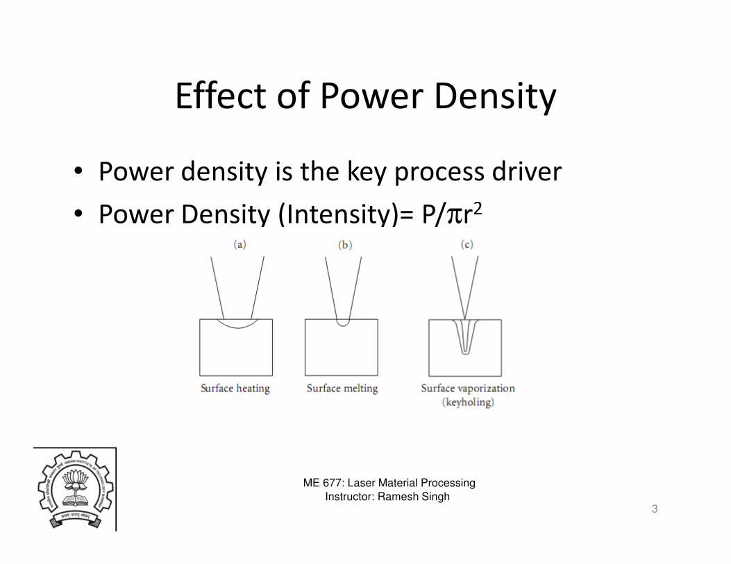
Effect of Power Density
• Power density is the key process driver
• Power Density (Intensity)= P/πr2
3

ME 677: Laser Material Processing
Instructor: Ramesh Singh
Process Variables for Material
Processing
4
• The other important process variables:

ME 677: Laser Material Processing
Instructor: Ramesh Singh
Interaction Time and Empirical Process
Chart• Interaction time, τ = 2 r/v
where r = beam radius and v = velocity
5

ME 677: Laser Material Processing
Instructor: Ramesh Singh
Structural Steel
6

ME 677: Laser Material Processing
Instructor: Ramesh Singh
Cutting
• Laser cutting is able to cut faster and with a
higher quality then competing processes:
– Punch, plasma, abrasive waterjet, ultrasonic,
oxyflame, sawing and milling
• Can be automated
• 80% industrial lasers in Japan are used for
metal cutting
7

ME 677: Laser Material Processing
Instructor: Ramesh Singh8

ME 677: Laser Material Processing
Instructor: Ramesh Singh
Typical Cutting Setup
9

ME 677: Laser Material Processing
Instructor: Ramesh Singh
Process Characteristics• It is one of the faster cutting processes.
• The work piece does not need clamping but workholding is advisable to avoid shifting with the table acceleration and for locating when using a CNC program
• Tool wear is zero since the process is a non contact cutting process.
• Cuts can be made in any direction polarization may affect process efficiency
• The noise level is low.
• The process can be easily automated with good prospects for adaptive control in the future.
• No expensive tooling changes are mainly "soft". That is they are only programming changes. Thus the process is highly flexible.
• Some materials can be stack cut, but there may be a problem with welding between layers.
• Nearly all engineering materials can be cut. They can be friable, brittle, electric conductors or non conductors, hard or soft. – Only highly reflective materials such as aluminium and copper can pose a
problem but with proper beam control these can be cut satisfactorily.
10
ME 677: Laser Material Processing
Instructor: Ramesh Singh
Process Response• The cut can have a very narrow kerf width giving a substantial saving in
material. (Kerf is the width of the cut opening)
• The cut edges can be square and not rounded as with most hot jet processes or other thermal cutting techniques.
• The cut edge can be smooth and clean. It is a finished cut, requiring no further cleaning or treatment.
• The cut edge can be directly re-welded with little to no surface preparation.
• There is no edge burr as with mechanical cutting techniques. Dross adhesion can usually be avoided.
• There is a very narrow HAZ (Heat Affected Zone) and very thin re-solidified layer of few µm, particularly on dross free cuts. There is negligible distortion.
• Blind cuts can be made in some materials, particularly those which volatilise, such as wood or acrylic.
• Cut depth depends on the laser power. 10-20mm is the current range for high quality cuts. Some very high power fiber lasers could cut 50 mm.
11

ME 677: Laser Material Processing
Instructor: Ramesh Singh
Dross
12

ME 677: Laser Material Processing
Instructor: Ramesh Singh
Process Mechanisms
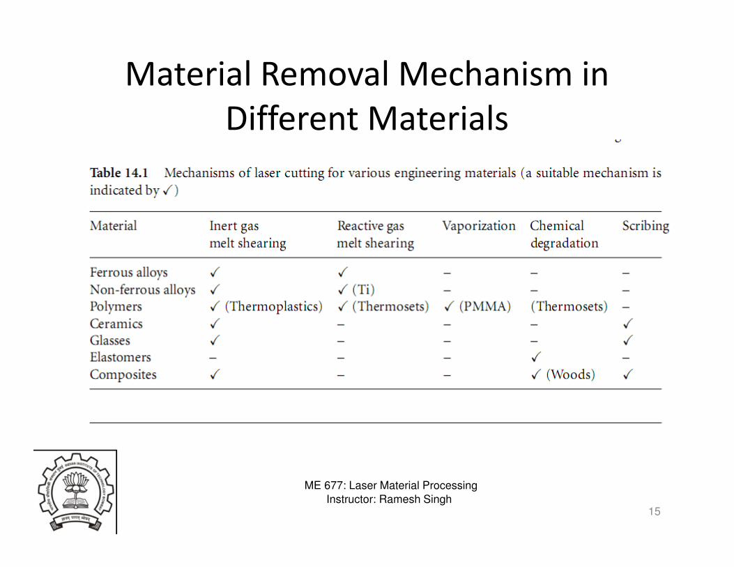
• The beam is traversed over a programmed path and material removal occurs due to multiple mechanisms
• Melting– Material exhibiting molten phase of low viscosity, notably metals and
alloys, and thermoplastics, are cut by the heating action of a beam of power density on the order of 104 Wmm−2
– The melt is assisted by shearing action of a stream of inert or active assist gas, results in formation of a molten channel through the material called a kerf (slot).
• Vaporisation– Suitable for materials that are not readily melted (some glasses,
ceramics and composites)
– Materials can be cut by vaporization that is induced by a higher beam power density (>104 Wmm−2)
• Chemical Degradation– A kerf can be formed in many organic materials by chemical
degradation caused by the heating action of the beam.
13

ME 677: Laser Material Processing
Instructor: Ramesh Singh14
ME 677: Laser Material Processing
Instructor: Ramesh Singh
Material Removal Mechanism in
Different Materials
15

ME 677: Laser Material Processing
Instructor: Ramesh Singh
Inert Gas Melt Shearing or Melt and Blow
16
Viewed from Top

ME 677: Laser Material Processing
Instructor: Ramesh Singh
Melt and Blow
• Once a penetration hole is made or the cut is
started from the edge, then
• A sufficiently strong gas jet could blow the
molten material out of the cut kerf to prevent the
temperature rise to the boiling point any further
• Cutting with inert gas jet requires only one tenth
of the power required for vaporization
• Note that the ratio latent heat of melting to
vaporization is 1:20.
17

ME 677: Laser Material Processing
Instructor: Ramesh Singh
Modeling of the Process
18
[ ]
[ ]vfp
vfp
LmLTCw
tV
P
LmLTCwtVP
'
'
++∆=
++∆=
η
ρ
ρη

ME 677: Laser Material Processing
Instructor: Ramesh Singh
Melt and Blow• The group [P/tV] is constant for the cutting of a given
material with a given beam.
19

ME 677: Laser Material Processing
Instructor: Ramesh Singh
Cutting Action
• The beam is incident on the surface
– Most of the beam passes into the hole or kerf
– some is reflected off the unmeltedsurface
– some may pass straight through.
• At slow speeds the melt starts at the leading edge of the beam and much of the beam passes clean through the kerf without touching if the material is sufficiently thin
20
ME 677: Laser Material Processing
Instructor: Ramesh Singh
Detailed Melting Blowing Mechanism
• The absorption is by two mechanisms:– Mainly by Fresnel absorption , i.e., direct interaction of the
beam with the material –
– By plasma absorption and reradiation. The plasma build up in cutting is not very significant due to the gas blowing it away.
• The power density on the cutting front is Fsinθ. This causes melting which is then blown away by the drag forces from the fast flowing gas stream.
• At the bottom of the kerf the melt is thicker due to deceleration of the film and surface tension retarding the melt from leaving.
• The gas stream ejects the molten droplets at the base of the cut into the atmosphere.
21

ME 677: Laser Material Processing
Instructor: Ramesh Singh
Formation of Striations• As the cut rate is increased the beam is automatically coupled to the work
piece more efficiently due to reduced losses through the kerf .
• Also the beam tends to ride ahead onto the unmelted material. When this occurs the power density increases since the surface is not sloped
• The melt proceeds faster and is swept down into the kerf as a step. As the step is swept down it leaves behind a mark on the cut edge called a striation.
• The cause of striations is disputed, there are many theories: – The step theory
– critical droplet size causing the melt to pulsate in size before it can be blown free
– The sideways burning theory.
• There are conditions under which no striations occur. These are governed by gas flow or by pulsing at the frequency of the natural striation
22

ME 677: Laser Material Processing
Instructor: Ramesh Singh
Striations
23

ME 677: Laser Material Processing
Instructor: Ramesh Singh
Reactive Fusion Cutting • If the assisting gas is also capable of reacting exothermically
an extra heat source is added to the process.
• The gas passing through the kerf is not only dragging the melt
away but also reacting with the melt.
• Usually the reactive gas is oxygen or some mixture containing
oxygen.
• The burning reaction starts usually at the ignition temperature
on the top.
• The oxide is formed and is blown into the kerf and will cover
the melt lower down which slows the reaction and may even
cause break in the striation lines .
24
ME 677: Laser Material Processing
Instructor: Ramesh Singh
Reactive Fusion ..• The amount of energy supplied by the burning reaction
varies with the material– with mild/stainless steel it is 60%
– with a reactive metal like titanium it is around 90%.
• Cutting speeds could be doubled using this technique.
• Typically, the faster the cut, the less heat penetration and the better the quality.
• A chemical change in the workpiece may happen due to reactive fusion. – With titanium this can be critical since the edge will have
some oxygen in it and will be harder and more liable to cracking.
– With mild steel there is no noticeable effect except a very thin re-solidified layer of oxide on the surface of the
25

ME 677: Laser Material Processing
Instructor: Ramesh Singh
Reactive Fusion…• The dross is an oxide (instead of metal)
– Mild steel flows well and does not adhere to the base metal
– With stainless steel the oxide is made up of high melting point components such as Cr2O3 (melting point~218O°C) and hence this freezes quicker causing a dross problem.
– Aluminum exhibits similar behavior
• Due to the burning reaction a further cause of striations is introduced
– In slow cutting (lower than the burning reaction speeds) the ignition temperature will be reached and burning will occur from the ignition point proceeding outward in all directions
26

ME 677: Laser Material Processing
Instructor: Ramesh Singh
Striations in Reactive Fusion Cutting
27

ME 677: Laser Material Processing
Instructor: Ramesh Singh
Controlled Fracture Process• Brittle material are vulnerable to thermal fracture can
be quickly and neatly severed by guiding a crack with a fine spot heated by a laser
• The laser heats a small volume of the surface causing it to expand and hence to cause tensile stresses all around it
• If there is a crack in this space, it will act as a stress raiser and the cracking will continue in direction of the hot spot
• The speed at which a crack can be guided is of the order of m/s
• When the crack approaches an edge, the stress fields become more complex
28

ME 677: Laser Material Processing
Instructor: Ramesh Singh
Controlled Fracture• Advantages:
– The speed, edge quality and precision are very
good in glass cutting.
– Effective for straight cuts
• Disadvantages:
– Difficult to create profiled cuts such as for the
manufacture of car wing mirrors
– Difficult to model and predict near the edges
29

ME 677: Laser Material Processing
Instructor: Ramesh Singh
Processing Range for Controlled
Fracture
30

ME 677: Laser Material Processing
Instructor: Ramesh Singh
Scribing• This is a process for making a groove or line of holes either
fully or partially penetrating
• This sufficiently weakens the structure so that it can be
mechanically broken
• Typically materials processed are silicon chips and alumina
substrates
• Quality is measured by the lack of debris and low heat
affected zone
• Thus low energy, high power density pulses are used to
remove the material principally as vapor
31

ME 677: Laser Material Processing
Instructor: Ramesh Singh
Vaporization Cutting• The focused beam in vaporization cutting first heats up the
surface to boiling point and generates a keyhole.
• The keyhole causes a sudden increase in the absorptivity due
to multiple reflections and the hole deepens quickly.
• As it deepens so vapor is generated and escapes blowing
ejecta out of the hole or kerf and stabilizing the molten walls
of the hole
• This is the usual method of cutting for pulsed lasers or in the
cutting of materials which do not melt such as wood, carbon,
and some plastics.
32

ME 677: Laser Material Processing
Instructor: Ramesh Singh
Vaoporization
• The rate of penetration of the beam into the
workpiece can be estimated from a lumped
heat capacity calculation assuming
– 1D heat flow
– Conduction is ignored
– The penetration rate is similar to or faster than
the rate of conduction
– volume removed per second per unit area =
penetration velocity, V m/s
33

ME 677: Laser Material Processing
Instructor: Ramesh Singh
Vaporization
• 1-D heat flow
34
( )[ ]0
0 TTCLLV
Fvpvf −++= ρ
( )
[ ]
2
0.5
0
2
0
( ) 1 ( )
(0, ) (2 / ) ( ) /
_ _
2
u
Bv
eierfc u u erf u
T t F K t
Time to vaporization
T Kt
F
π
α π
π
α
−
= − −
=
=

ME 677: Laser Material Processing
Instructor: Ramesh Singh
Cold Cutting
• High powered UV Excimer lasers exhibit cold
cutting
– The energy of the ultraviolet photon is 4.9eV which is
similar to the bond energy for many organic materials.
– If a bond is struck by such a photon then it may break
– When this radiation is shone onto plastic with a
sufficient flux of photons that there is at least one
photon/bond then the material just disappears
without heating leaving a hole with no debris or edge
damage
35

ME 677: Laser Material Processing
Instructor: Ramesh Singh
Picture of Hair Micromachining via
Excimer
36
ME 677: Laser Material Processing
Instructor: Ramesh Singh
Effect of Spot Size
• The principle parameters are laser power,
traverse speed, spot size and material thickness .
• Spot size acts in two ways:
– Firstly, a decrease in spot size will increase the power
density which affects the absorption and
– Secondly, it will decrease the cut width.
• Lasers with stable power and low order modes -
usually true TEMoo modes cut considerably
better than other modes
37

ME 677: Laser Material Processing
Instructor: Ramesh Singh
Spot Size
38

ME 677: Laser Material Processing
Instructor: Ramesh Singh
Effect of Beam Polarization
• The maximum cutting speed could be doubled, cutting in one
direction as opposed to one at right angles when cutting with
a plane polarised laser beam.
• Nearly all high powered lasers have folded cavities which
favours the amplification of radiation whose electric vector is
at right angles to the plane of incidence.
39

ME 677: Laser Material Processing
Instructor: Ramesh Singh
Wavelength
• The shorter the wavelength the higher the
absorptivity for most metals
• Thus YAG radiation is preferable to CO2
radiation but the poor mode structure of most
YAG lasers the benefit is offset
• Fiber lasers with good beam mode could have
an advantage
40

ME 677: Laser Material Processing
Instructor: Ramesh Singh
Summary
• Basics of laser cutting
• Mechanisms
• Factors affecting laser cutting
41


