10/15/2015 1 IIT Kanpur Kanpur, India (208016) www.iitk.ac.in/erl Laser Diagnostic Techniques for Engine Research Dr. Avinash Kumar Agarwal, Associate Professor, Engine Research Laboratory, Department of Mechanical Engineering, Indian Institute of Technology Kanpur [email protected]Engine Research Laboratory, IIT Kanpur Optical Diagnostics Increasing Environmental problems - more stringent Emission Control Norms Demand to minimize fuel consumption Better understanding of in-cylinder processes required To simulate fuel injection and combustion in the cylinder To use optical diagnostic techniques to visualize the in-cylinder processes Even the simulation results need to be verified experimentally using Optical Diagnostic Techniques
Transcript
10/15/2015
1
IIT Kanpur Kanpur, India (208016)
www.iitk.ac.in/erl
Laser Diagnostic Techniques for Engine Research
Dr. Avinash Kumar Agarwal, Associate Professor,
Engine Research Laboratory, Department of Mechanical Engineering, Indian Institute of Technology Kanpur
Increasing Environmental problems - more stringent Emission Control Norms
Demand to minimize fuel consumption
Better understanding of in-cylinder processes required
To simulate fuel injection and combustion in the cylinder
To use optical diagnostic techniques to visualize the in-cylinder processes
Even the simulation results need to be verified experimentally using Optical
Diagnostic Techniques
10/15/2015
2
Engine Research Laboratory, IIT Kanpur
Very high non-steady pressure and temperature conditions; high mechanical and
thermal stresses
proper lubrication not possible, liner heating
fowling of optical access window; need frequent cleaning
supporting structure should not block the optical access
requirement of a ‘flat optical window’
aberration due to unwanted scattering
maintaining realistic engine geometry
Optical Access: Major Challenges
Engine Research Laboratory, IIT Kanpur
Optical Access
Optical access is usually obtained by:
Full Optical Access:
Transparent Piston Head, and
Transparent Cylinder Liner
Endoscopic Access:
Optical Fiber based Endoscopic windows
Common Materials used:
Quartz
Sapphire
10/15/2015
3
Engine Research Laboratory, IIT Kanpur
Full Optical Access vs. Endoscopic Access
Full Optical Access:
The optical access is maximized to allow application of complex optical diagnostic techniques while maintaining minimum necessary operability of the engine or engine components
Full optical access allows a wide range of diagnostics to be applied
Endoscopic Access:
Full engine operability is maintained while optical access and diagnostic techniques are tailored to the diagnostic demand and the restraints of engine operation
Endoscopic access puts the emphasis on organizing and extending realistic engine operation conditions
Engine Research Laboratory, IIT Kanpur
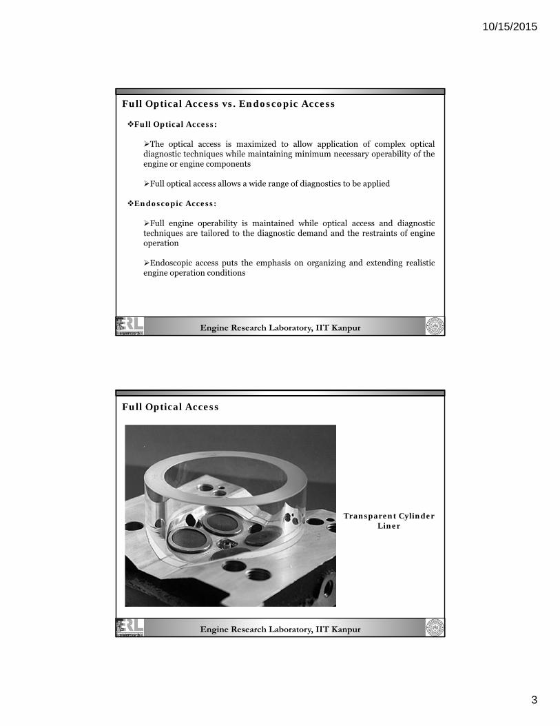
Full Optical Access
Transparent Cylinder Liner
10/15/2015
4
Engine Research Laboratory, IIT Kanpur
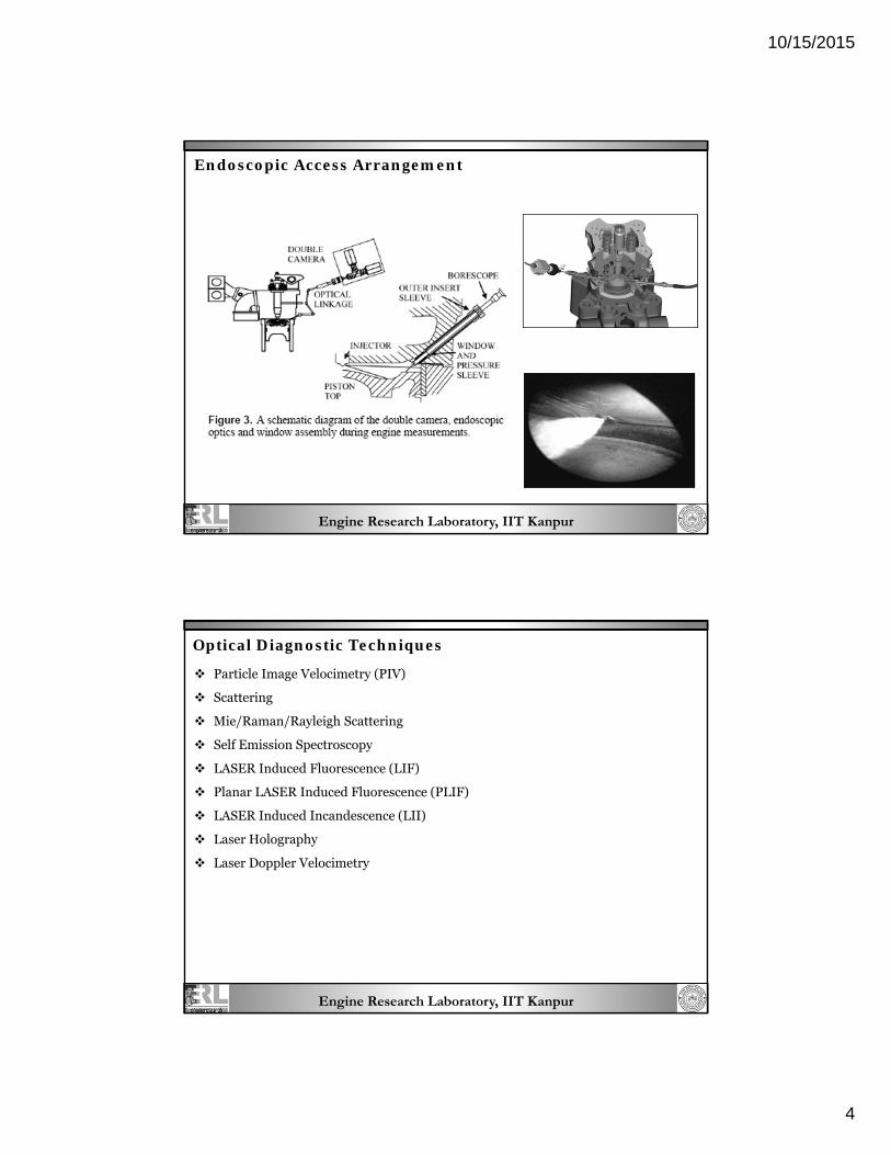
Endoscopic Access Arrangement
Engine Research Laboratory, IIT Kanpur
Optical Diagnostic Techniques
Particle Image Velocimetry (PIV)
Scattering
Mie/Raman/Rayleigh Scattering
Self Emission Spectroscopy
LASER Induced Fluorescence (LIF)
Planar LASER Induced Fluorescence (PLIF)
LASER Induced Incandescence (LII)
Laser Holography
Laser Doppler Velocimetry
10/15/2015
5
Engine Research Laboratory, IIT Kanpur
Particle Image Velocimetry (PIV) for IC Engines
Engine Research Laboratory, IIT Kanpur
Technique – Study flow of a Fluid.
The flow is illuminated with a double pulsed light – sheet and the positions of a
large number of tracer particles are recorded with a photographic camera viewing
normal to the plane of the sheet.
What is PIV?
Advantages of PIV
Non-intrusive into the flow field being studied.
2D or 3D full-field flow measurements can be made.
Instantaneous velocity fields are obtained.
Capability for studying multiphase flows.
10/15/2015
6
Engine Research Laboratory, IIT Kanpur
Single and multi-phase channel flows .
Steam bubble collapse
Flow around cylinders in a channel
Bubbly pipe flows
Free surface experiments
Sprays
Heated cavity flows
PIV can be Used to Study:
Engine Research Laboratory, IIT Kanpur
PIV measures whole velocity fields by taking two images shortly after each other
and calculating the distance individual particles travelled within this time. From
the known time difference and the measured displacement the velocity is
calculated.
Principle of PIV
3-D PIV
based on the principle of stereoscopic imaging: two cameras capture the image of
the illuminated particles from different angles and then the images are digitally
combined to obtain a 3-D images.
10/15/2015
7
Engine Research Laboratory, IIT Kanpur
Seeding: The flow medium is seeded with particles, droplets or bubbles
Double Pulsed Laser: Two laser pulses illuminate these particles with short time
difference
Light Sheet Optics: Laser light is formed into a thin light plane guided into the
flow medium
CCD Camera: A fast frame-transfer CCD captures two frames exposed by laser
pulses
Software: Calculates the velocities and makes Velocity Maps
Components
Engine Research Laboratory, IIT Kanpur
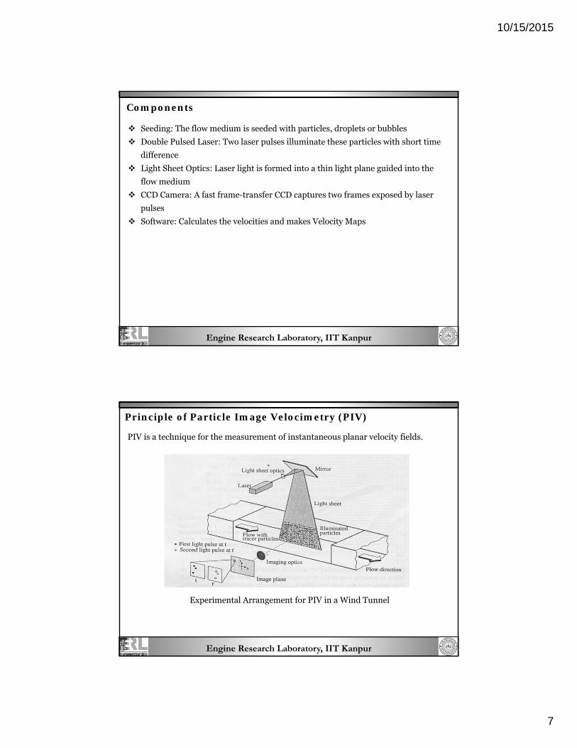
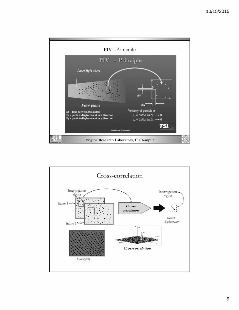
Principle of Particle Image Velocimetry (PIV)
PIV is a technique for the measurement of instantaneous planar velocity fields.
Experimental Arrangement for PIV in a Wind Tunnel
10/15/2015
8
Engine Research Laboratory, IIT Kanpur
Particle Image Velocimetry (PIV)
Definition
– An optical imaging technique to measure fluid or particulate velocity vectors at many (eg. Thousands) points in a flow field simultaneously.
– Measurements (2 or 3 components of velocity) usually made in “Planar slices” of the flow field.
Accuracy and Spatial resolution
– Comparable to LDV and HWA.
Engine Research Laboratory, IIT Kanpur
Particle Image Velocimetry
10/15/2015
9
Engine Research Laboratory, IIT Kanpur
PIV - Principle
Cross-correlation
particle displacement
Interrogation region
Crosscorrelation
Vector field
Cross- correlation
frame 1
frame 2
Interrogation region
10/15/2015
10
Engine Research Laboratory, IIT Kanpur
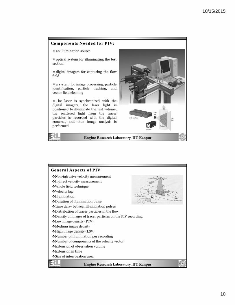
Components Needed for PIV:
an illumination source
optical system for illuminating the test section.
digital imagers for capturing the flow field
a system for image processing, particle identification, particle tracking, and vector field cleaning
The laser is synchronized with the digital imagers, the laser light is positioned to illuminate the test volume, the scattered light from the tracer particles is recorded with the digital cameras, and then image analysis is performed.
Engine Research Laboratory, IIT Kanpur
General Aspects of PIV
Non-intrusive velocity measurement
Indirect velocity measurement
Whole field technique
Velocity lag
Illumination
Duration of illumination pulse
Time delay between illumination pulses
Distribution of tracer particles in the flow
Density of images of tracer particles on the PIV recording
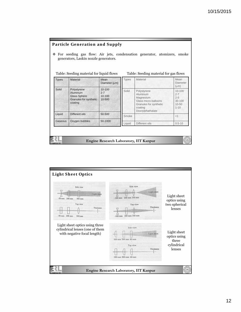
Table: Seeding material for liquid flows Table: Seeding material for gas flows
Engine Research Laboratory, IIT Kanpur
Light Sheet Optics
Light sheet optics using three cylindrical lenses (one of them
with negative focal length)
Light sheet optics using
two spherical lenses
Light sheet optics using
three cylindrical
lenses
10/15/2015
13
Engine Research Laboratory, IIT Kanpur
PIV Recording Techniques Single frame/multi-exposure PIV Multi-frame/single exposure PIV
Types of CCD Camera Full-frame CCD Frame transfer CCD Interline transfer CCD Full-frame interline transfer CCD
POST-processing of PIV Data Replacement of incorrect data Data reduction Analysis of the information Presentation and animation of the information
Engine Research Laboratory, IIT Kanpur
Study of IC Engine Charge Motion Using PIV :
Charge motion within a IC Engine has a Significant effect on:
Power Output
Fuel Efficiency
Exhaust Emissions
The combustion behavior of internal-combustion spark-ignition (SI) engines is
strongly dependent on:
The quality of the mixture processing, which in turn is affected by the motion of
the in-cylinder flow.
Fresh charge, and residual gas resulting from the former combustion cycle, have
to form a proper mixture.
In addition, a certain level of turbulence is required at the time of ignition to
perform an accelerated flame propagation and thereby a highly efficient
combustion.
Therefore, it is highly importance to collect detailed information on the in-
cylinder flow field and its temporal development during the combustion cycle. PIV
has proven to be a helpful tool in order to analyze the air-flow in the cylinder.
10/15/2015
14
Engine Research Laboratory, IIT Kanpur
Advantages of PIV over other Techniques such as
1. Streak Photography
2. PTV ( Particle Tracing Techniques)
Advantages:
1. The identification of individual particle image, not necessary in PIV interrogation
2. PIV allows measurement of instantaneous velocity on a fine , regular measurement grid without significant interpolation.
Limitations of PIV :
1. The technique has only technological limitations to achieve a temporal resolution due to the illumination source ( lasers ) and the recording media ( CCD) frequencies which are available today .
Engine Research Laboratory, IIT Kanpur
Two-Colour Particle Image Velocimetry Analysis of the Effects of Inlet Port Deactivation on the Velocity Flow Field in a Fired
Liquid Fuelled Spark Ignition Engine
M J Haste, C P Garner*, A K Agarwal** N A Halliwell
Department of Mechanical Engineering
Loughborough University*
Loughborough, Leicestershire, England LE11 3TU
Indian Institute of Technology Kanpur **, India
10/15/2015
15
Engine Research Laboratory, IIT Kanpur
Fluid motion within IC engine fundamentally affects
engine performance and emissions.
To analyze and optimize complex coupled processes
inside and between automotive components and
structure such as the reduction of a vehicle’s interior
or outer acoustic noise, including brake noise, and
the combustion analysis for diesel and gasoline
engines to further reduce fuel consumption and
pollution.
Deeper insight in modern engine combustion
concepts such as flow generation, fuel injection and
spray formation, atomization and mixing, ignition
and combustion, and formation and reduction of
pollutants.
The need for an non-intrusive measurement system.
Laser Assisted Diagnostics is an important tool for
such measurements.
Engine Manufacturers are developing more fuel efficient, more refined and which produce lower amount of pollutants.
Engine in-cylinder fluid
motion is known to
fundamentally affect the
combustion process.
It is important to understand combustion phenomenon under different operating conditions such as valve deactivation, port injection and variable injection timing.
Introduction
Engine Research Laboratory, IIT Kanpur
Objective
PIV Is used to investigate the in-cylinder fluid motions and its interaction with propagating flame in a production geometry pentroof multi-valve optical SI engine, fired using liquid fuel.
The flow structures distribution were obtained with both open and closed inlet valve injection timing under normal running and with a single inlet port deactivated.
This allows mapping of the flame position and study of the fluid motion ahead of flame front.
Two color PIV is used to obtain full field instantaneous velocity data over planer regions within the combustion chamber with a spatial resolution of less than 1.5 mm. Si oil seed burn in the flame front hence it is possible to distinguish the burnt and unburned region of the inc-cylinder flow.
Twin Oscillator, twin amplifier Nd:YAG laser, frequency doubled to generate green light at 532 nm. (Pulse duration 10µs)
Average diameter of Si oil droplets seed: 1.4μm
10/15/2015
17
Engine Research Laboratory, IIT Kanpur
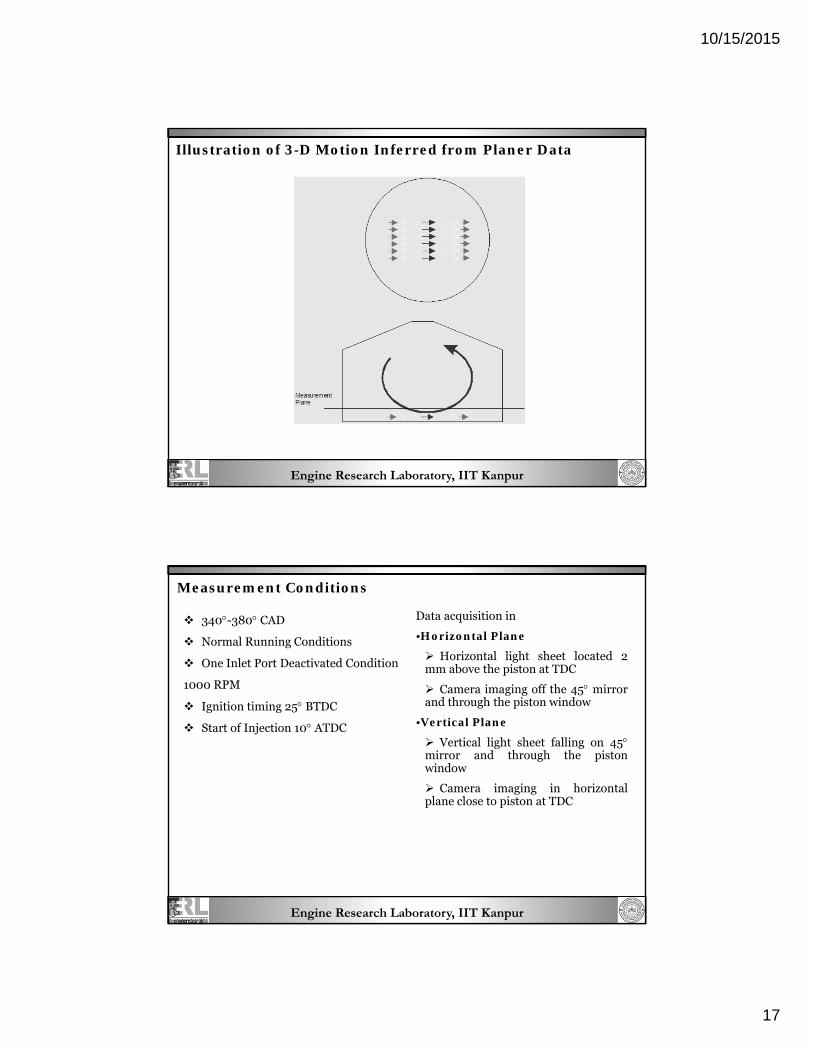
Illustration of 3-D Motion Inferred from Planer Data
Engine Research Laboratory, IIT Kanpur
340-380 CAD
Normal Running Conditions
One Inlet Port Deactivated Condition
1000 RPM
Ignition timing 25 BTDC
Start of Injection 10 ATDC
Measurement Conditions
Data acquisition in
•Horizontal Plane
Horizontal light sheet located 2 mm above the piston at TDC
Camera imaging off the 45 mirror and through the piston window
•Vertical Plane
Vertical light sheet falling on 45 mirror and through the piston window
Camera imaging in horizontal plane close to piston at TDC
10/15/2015
18
Engine Research Laboratory, IIT Kanpur
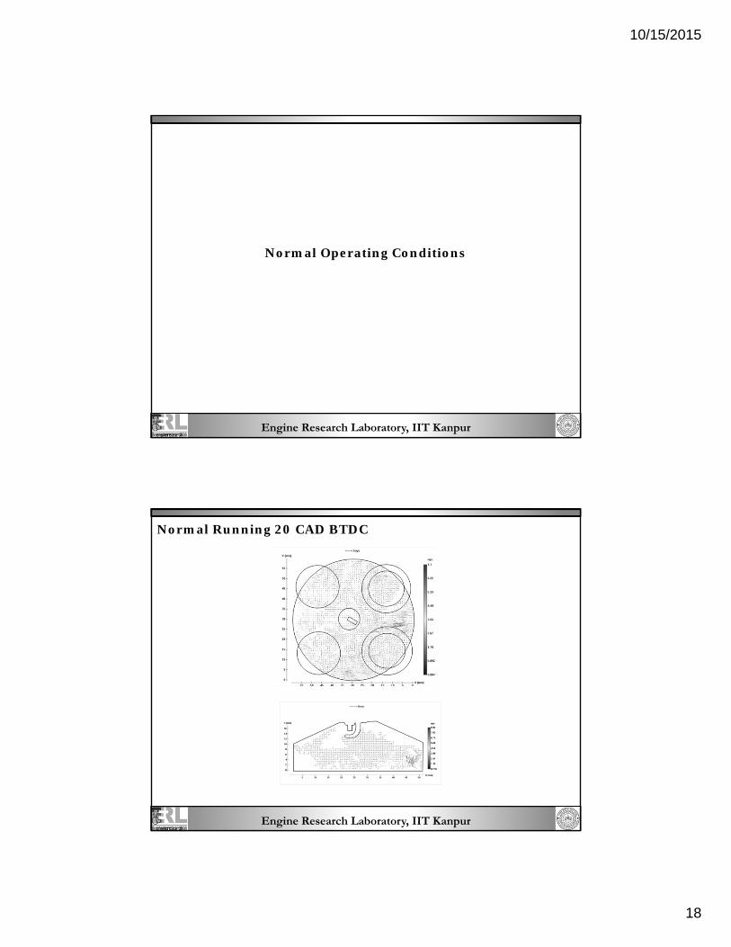
Normal Operating Conditions
Engine Research Laboratory, IIT Kanpur
Normal Running 20 CAD BTDC
10/15/2015
19
Engine Research Laboratory, IIT Kanpur
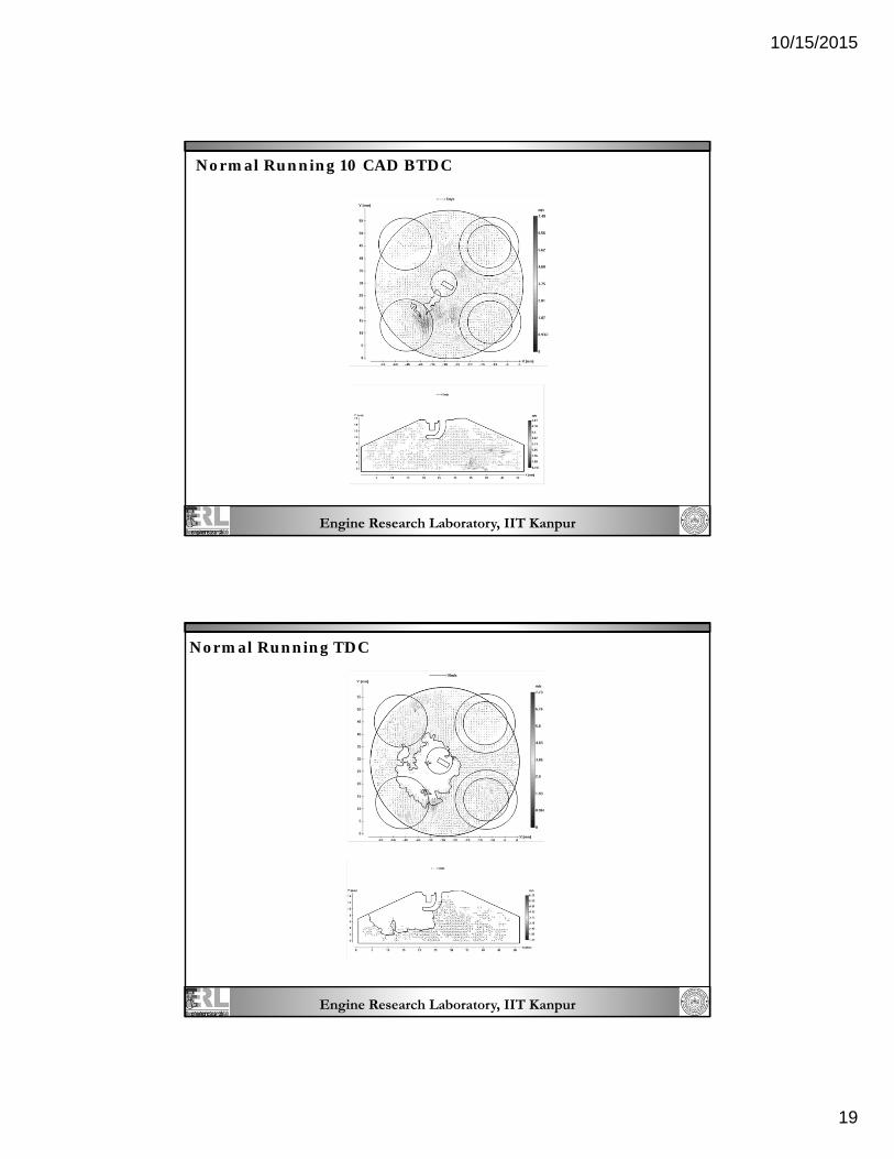
Normal Running 10 CAD BTDC
Engine Research Laboratory, IIT Kanpur
Normal Running TDC
10/15/2015
20
Engine Research Laboratory, IIT Kanpur
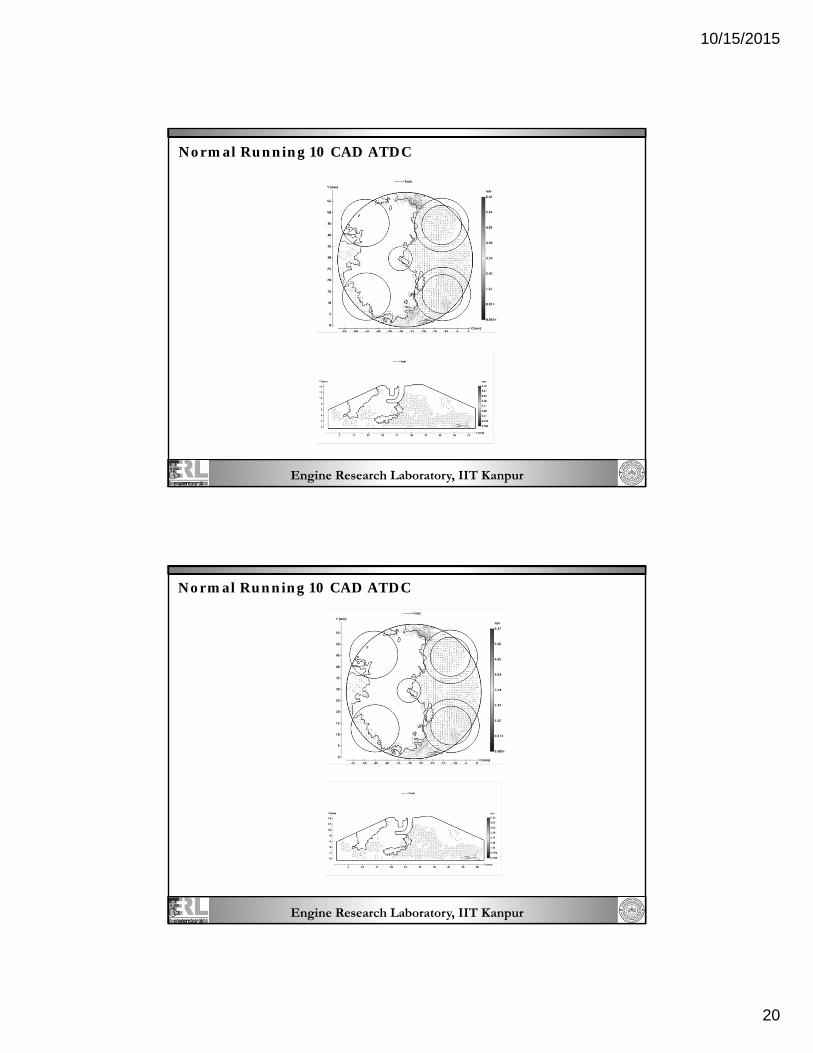
Normal Running 10 CAD ATDC
Engine Research Laboratory, IIT Kanpur
Normal Running 10 CAD ATDC
10/15/2015
21
Engine Research Laboratory, IIT Kanpur
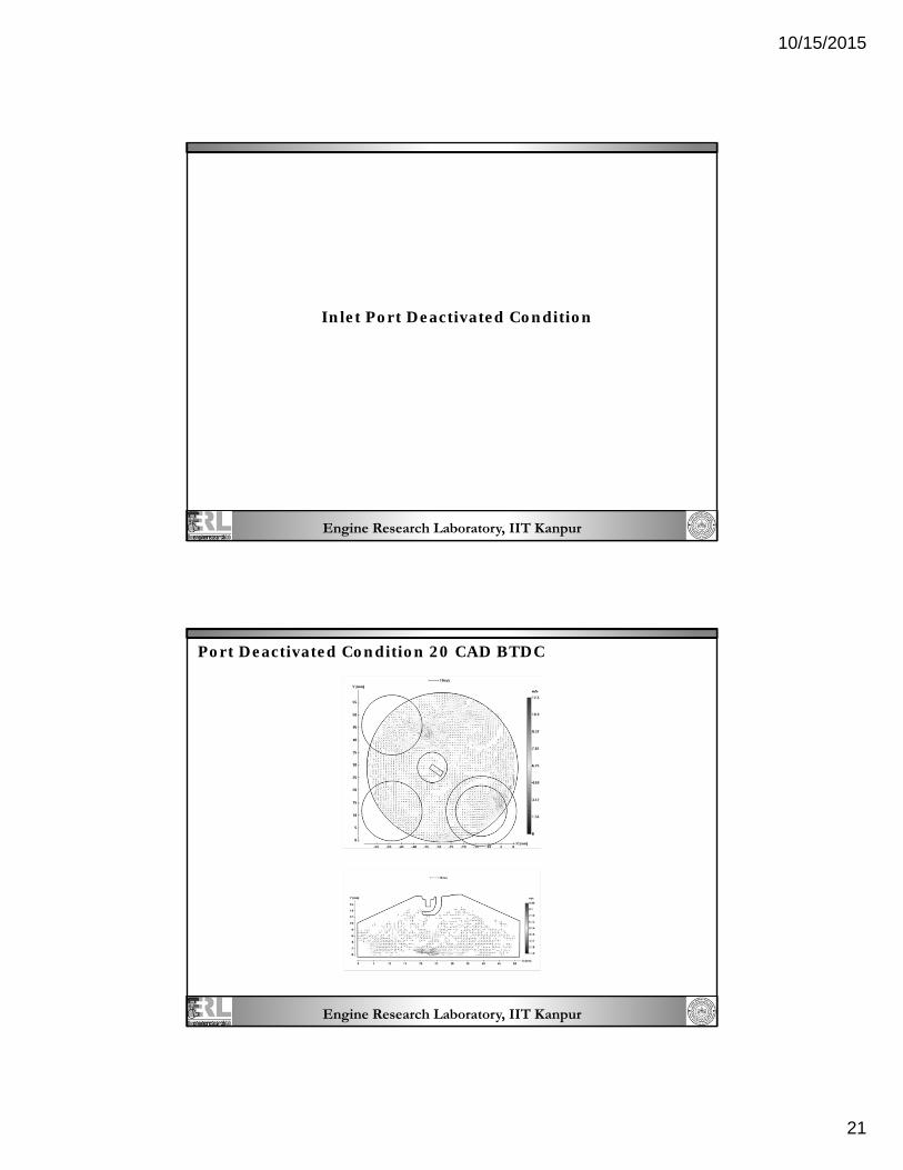
Inlet Port Deactivated Condition
Engine Research Laboratory, IIT Kanpur
Port Deactivated Condition 20 CAD BTDC
10/15/2015
22
Engine Research Laboratory, IIT Kanpur
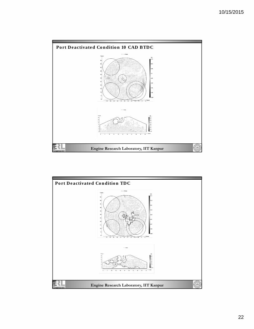
Port Deactivated Condition 10 CAD BTDC
Engine Research Laboratory, IIT Kanpur
Port Deactivated Condition TDC
10/15/2015
23
Engine Research Laboratory, IIT Kanpur
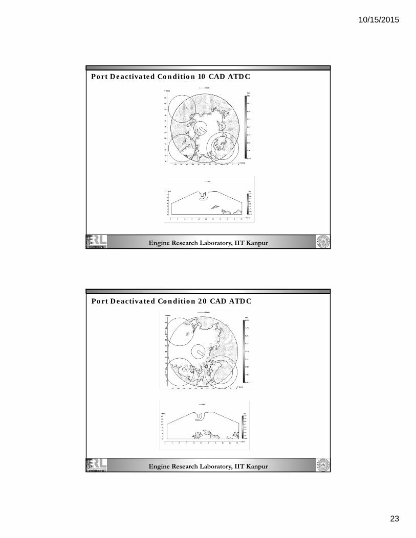
Port Deactivated Condition 10 CAD ATDC
Engine Research Laboratory, IIT Kanpur
Port Deactivated Condition 20 CAD ATDC
10/15/2015
24
Engine Research Laboratory, IIT Kanpur
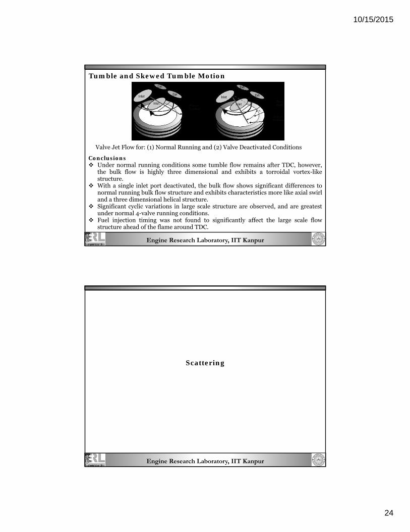
Tumble and Skewed Tumble Motion
Valve Jet Flow for: (1) Normal Running and (2) Valve Deactivated Conditions
Conclusions Under normal running conditions some tumble flow remains after TDC, however,
the bulk flow is highly three dimensional and exhibits a torroidal vortex-like structure.
With a single inlet port deactivated, the bulk flow shows significant differences to normal running bulk flow structure and exhibits characteristics more like axial swirl and a three dimensional helical structure.
Significant cyclic variations in large scale structure are observed, and are greatest under normal 4-valve running conditions.
Fuel injection timing was not found to significantly affect the large scale flow structure ahead of the flame around TDC.
Engine Research Laboratory, IIT Kanpur
Scattering
10/15/2015
25
Engine Research Laboratory, IIT Kanpur
Scattering
Principle: When light interacts with matter different scattering processes can happen simultaneously or exclusively depending on chemical and physical properties of the scatterer. Therefore scattered light contains information about the material, it's size and environmental conditions like temperature. Mie imaging: elastic scattering; same wavelength as the incident light; intensity is proportional to the size of the scattering particles; for particles which are ‘large’ compared to the wavelength of the incident light. Rayleigh imaging: elastic scattering; same wavelength as the incident light; intensity is proportional to the intensity of incident light, a material-dependant constant and the number density of particles; for particles are ‘small’ compared to the wavelength of the incident light. Raman imaging: inelastic scattering; shows a spectral response that is shifted from the laser line and characteristic for the Raman active molecules; do not suffer from ‘collision quenching’.
spray analysis (particle size distribution and spray geometry)
general imaging tasks
Rayleigh Scattering: combustion processes
pollutant formation
total gas density
temperature fields
Raman Scattering: majority species concentrations
space and time-resolved
mixture fractions
local temperature
10/15/2015
26
Engine Research Laboratory, IIT Kanpur
Self Emission Spectroscopy
Principle:
During combustion many species get excited due to the high temperatures
involved, as their electrons come back to the ground state they emit light which
can be resolved to give the ‘fingerprint spectra’ studying which the type and
concentration of the species can be determined
The two-colour method relies on the measurement of the radiation intensity
from soot particles which are generated during combustion. The radiation
intensity can then be measured at two wavelengths.
Applications
Flame temperature, flame location & stability
Spatial Soot concentration
excited species distribution like OH*, CH*, C2*
on-set of ignition
Engine Research Laboratory, IIT Kanpur
Laser Induced Fluorescence (LIF)
10/15/2015
27
Engine Research Laboratory, IIT Kanpur
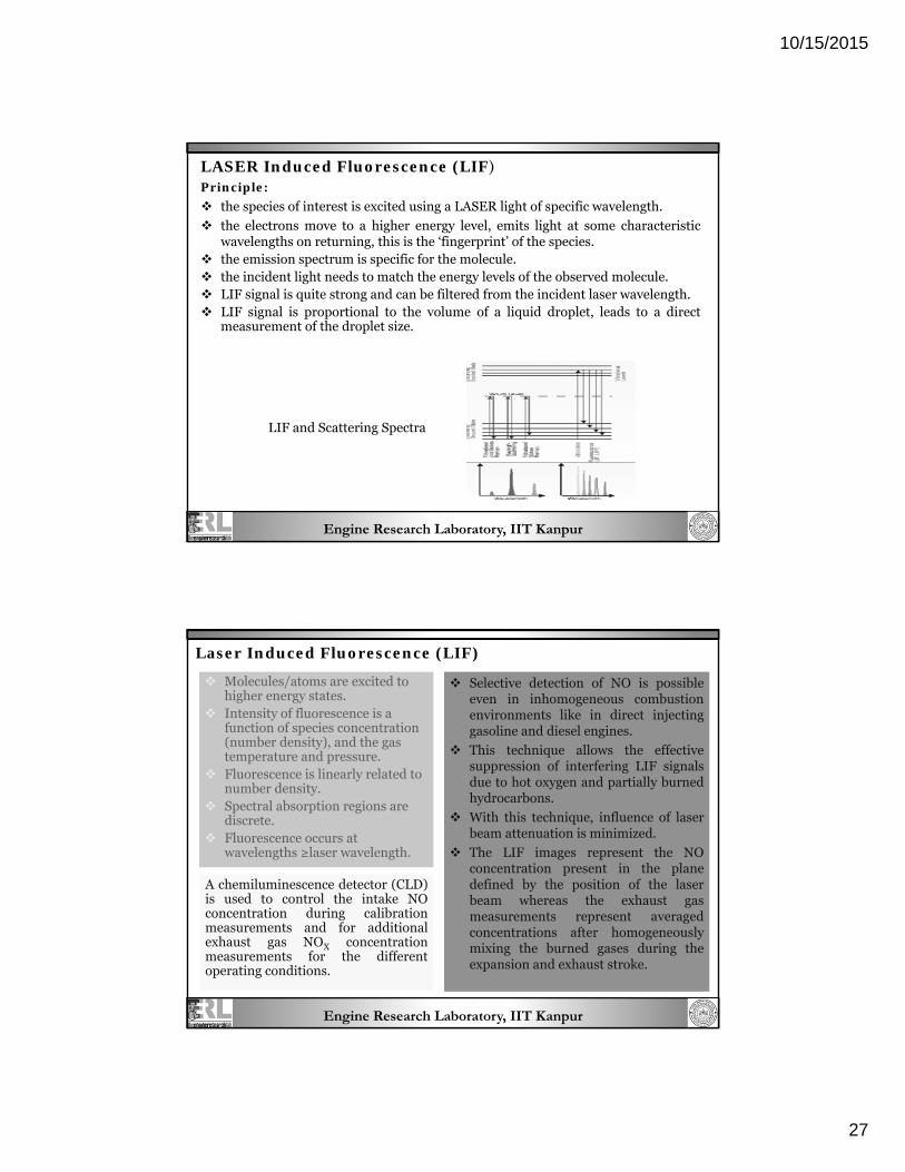
LASER Induced Fluorescence (LIF) Principle:
the species of interest is excited using a LASER light of specific wavelength.
the electrons move to a higher energy level, emits light at some characteristic wavelengths on returning, this is the ‘fingerprint’ of the species.
the emission spectrum is specific for the molecule. the incident light needs to match the energy levels of the observed molecule. LIF signal is quite strong and can be filtered from the incident laser wavelength. LIF signal is proportional to the volume of a liquid droplet, leads to a direct
measurement of the droplet size.
LIF and Scattering Spectra
Engine Research Laboratory, IIT Kanpur
Laser Induced Fluorescence (LIF)
Molecules/atoms are excited to higher energy states.
Intensity of fluorescence is a function of species concentration (number density), and the gas temperature and pressure.
Fluorescence is linearly related to number density.
Spectral absorption regions are discrete.
Fluorescence occurs at wavelengths ≥laser wavelength.
Selective detection of NO is possible even in inhomogeneous combustion environments like in direct injecting gasoline and diesel engines.
This technique allows the effective suppression of interfering LIF signals due to hot oxygen and partially burned hydrocarbons.
With this technique, influence of laser beam attenuation is minimized.
The LIF images represent the NO concentration present in the plane defined by the position of the laser beam whereas the exhaust gas measurements represent averaged concentrations after homogeneously mixing the burned gases during the expansion and exhaust stroke.
A chemiluminescence detector (CLD) is used to control the intake NO concentration during calibration measurements and for additional exhaust gas NOX concentration measurements for the different operating conditions.
10/15/2015
28
Engine Research Laboratory, IIT Kanpur
LASER Induced Fluorescence (LIF)
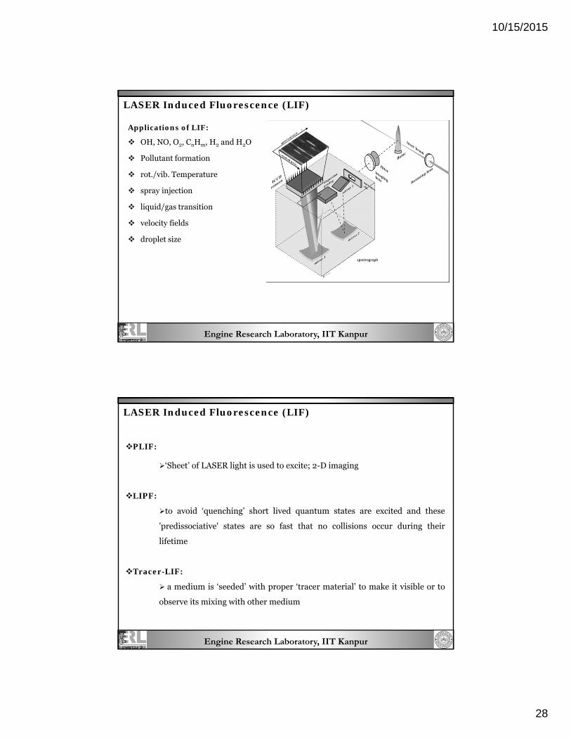
Applications of LIF:
OH, NO, O2, CnHm, H2 and H2O
Pollutant formation
rot./vib. Temperature
spray injection
liquid/gas transition
velocity fields
droplet size
Engine Research Laboratory, IIT Kanpur
LASER Induced Fluorescence (LIF)
PLIF: ‘Sheet’ of LASER light is used to excite; 2-D imaging
LIPF:
to avoid ‘quenching’ short lived quantum states are excited and these
'predissociative' states are so fast that no collisions occur during their
lifetime
Tracer-LIF:
a medium is ‘seeded’ with proper ‘tracer material’ to make it visible or to
observe its mixing with other medium
10/15/2015
29
Engine Research Laboratory, IIT Kanpur
Case Studies of LIF
LIF imaging measurements based on in-cylinder-formed formaldehyde and 3-
pentanone as a fuel tracer under controlled auto-igniting (CAI) conditions.
Fuel consisting of 50% n-heptane and 50% iso-octane is used to ensure stable
auto-ignition while having the reduced compression ratio and temperature
typical of most optically accessible engines.
Optically Accessible DI Gasoline Engine
Schematic of Laser-Based Imaging Setup
Engine Research Laboratory, IIT Kanpur
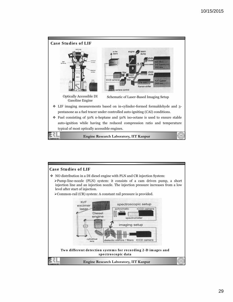
NO distribution in a DI diesel engine with PLN and CR injection System:
Pump-line-nozzle (PLN) system: it consists of a cam driven pump, a short injection line and an injection nozzle. The injection pressure increases from a low level after start of injection.
Common-rail (CR) system: A constant rail pressure is provided.
Two different detection systems for recording 2-D images and spectroscopic data
Case Studies of LIF
10/15/2015
30
Engine Research Laboratory, IIT Kanpur
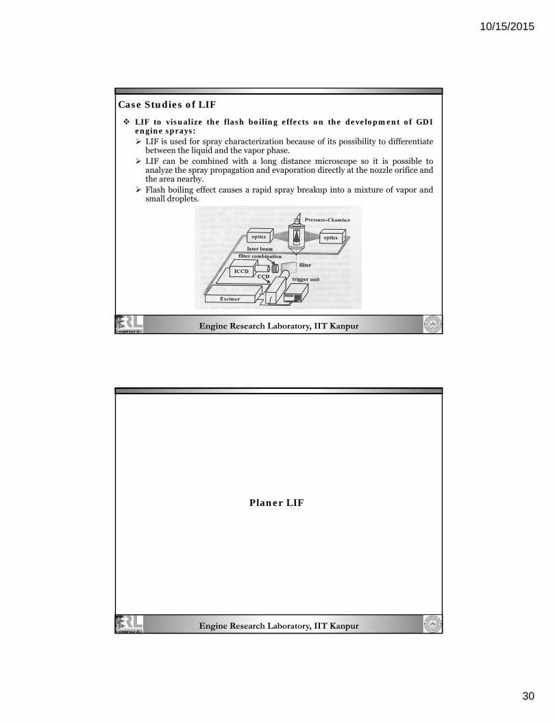
LIF to visualize the flash boiling effects on the development of GDI engine sprays: LIF is used for spray characterization because of its possibility to differentiate
between the liquid and the vapor phase. LIF can be combined with a long distance microscope so it is possible to
analyze the spray propagation and evaporation directly at the nozzle orifice and the area nearby.
Flash boiling effect causes a rapid spray breakup into a mixture of vapor and small droplets.
Case Studies of LIF
Engine Research Laboratory, IIT Kanpur
Planer LIF
10/15/2015
31
Engine Research Laboratory, IIT Kanpur
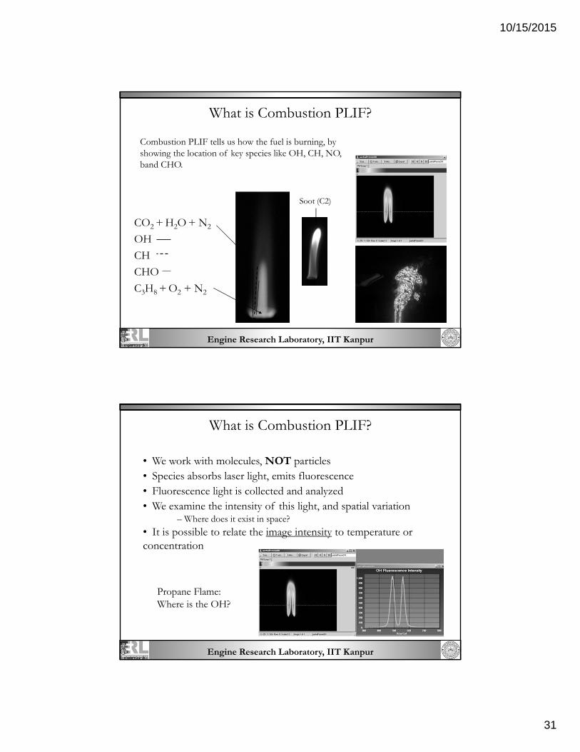
What is Combustion PLIF?
Combustion PLIF tells us how the fuel is burning, by showing the location of key species like OH, CH, NO, band CHO.
CO2 + H2O + N2
OH
CH
CHO
C3H8 + O2 + N2
OH
Soot (C2)
Engine Research Laboratory, IIT Kanpur
What is Combustion PLIF?
• We work with molecules, NOT particles • Species absorbs laser light, emits fluorescence • Fluorescence light is collected and analyzed • We examine the intensity of this light, and spatial variation – Where does it exist in space?
• It is possible to relate the image intensity to temperature or concentration
Propane Flame: Where is the OH?
10/15/2015
32
Engine Research Laboratory, IIT Kanpur
How does PLIF work ?
A sheet of laser light illuminates a plane
A target species within the plane of the sheet absorbs light at the wavelength of the laser, exciting the species to a higher energy state
The high energy state decays to a lower energy state, emitting a photon
The emitted photons are collected on a CCD array
The digital image is interpreted
Engine Research Laboratory, IIT Kanpur
Measurements with PLIF
Temperature or concentration
– Heat transfer – Mass transfer – Mixing
pH
– Possible but not common Species measurement
– Used to monitor chemical reaction intermediates – Combustion, flame, and engine studies
Pressure
– Requires calculations based on known temperature, concentration
Image Capture Subsystem – CCD Camera, Intensified CCD Camera. – Capture the Fluorescence image and record them.
Analysis Subsystem – Calculates and Displays a two-dimensional scalar field from the fluorescence image
field.
Engine Research Laboratory, IIT Kanpur
Planer LIF
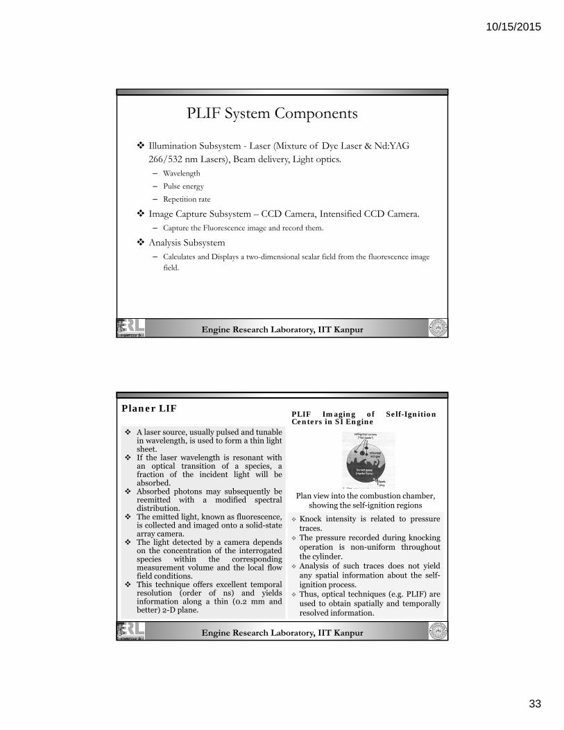
A laser source, usually pulsed and tunable in wavelength, is used to form a thin light sheet.
If the laser wavelength is resonant with an optical transition of a species, a fraction of the incident light will be absorbed.
Absorbed photons may subsequently be reemitted with a modified spectral distribution.
The emitted light, known as fluorescence, is collected and imaged onto a solid-state array camera.
The light detected by a camera depends on the concentration of the interrogated species within the corresponding measurement volume and the local flow field conditions.
This technique offers excellent temporal resolution (order of ns) and yields information along a thin (0.2 mm and better) 2-D plane.
PLIF Imaging of Self-Ignition Centers in SI Engine
Plan view into the combustion chamber, showing the self-ignition regions
Knock intensity is related to pressure traces.
The pressure recorded during knocking operation is non-uniform throughout the cylinder.
Analysis of such traces does not yield any spatial information about the self-ignition process.
Thus, optical techniques (e.g. PLIF) are used to obtain spatially and temporally resolved information.
10/15/2015
34
Engine Research Laboratory, IIT Kanpur
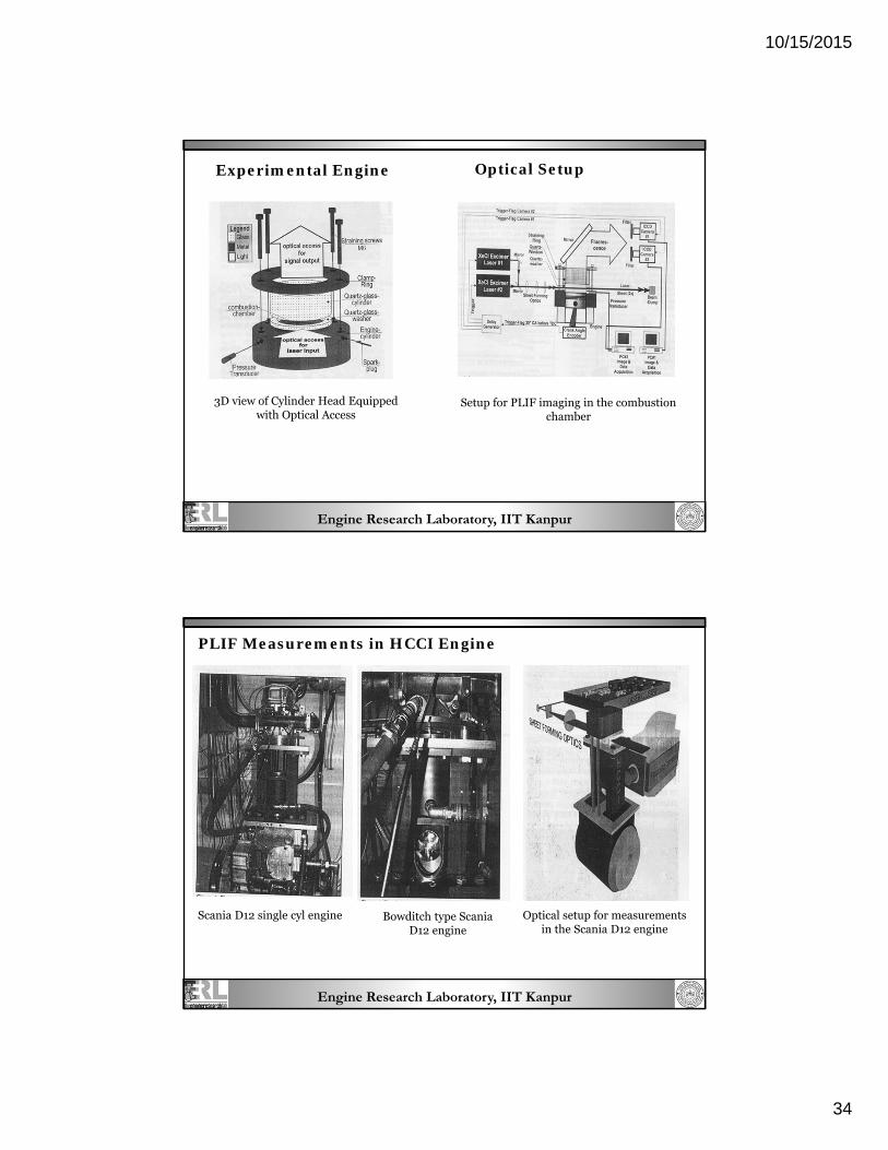
Experimental Engine
3D view of Cylinder Head Equipped with Optical Access
Optical Setup
Setup for PLIF imaging in the combustion chamber
Engine Research Laboratory, IIT Kanpur
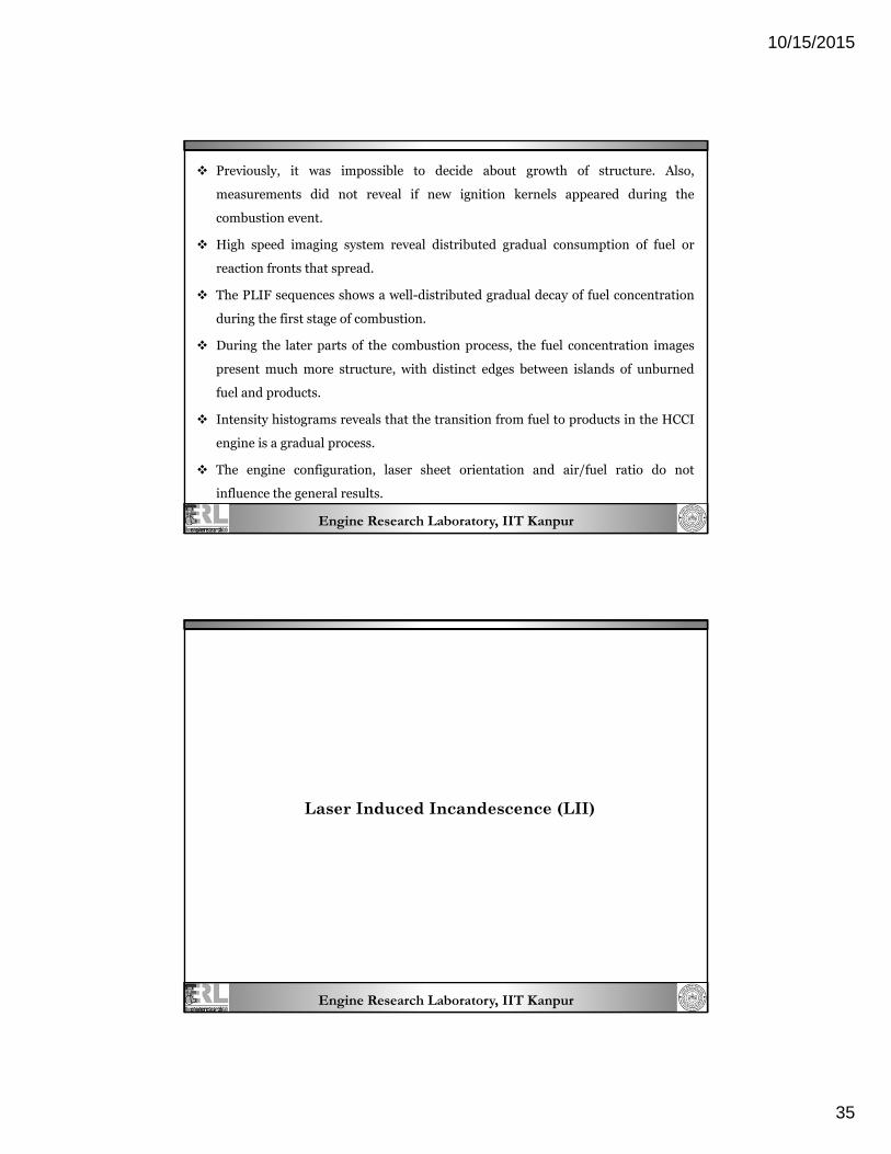
PLIF Measurements in HCCI Engine
Scania D12 single cyl engine Bowditch type Scania D12 engine
Optical setup for measurements in the Scania D12 engine
10/15/2015
35
Engine Research Laboratory, IIT Kanpur
Previously, it was impossible to decide about growth of structure. Also,
measurements did not reveal if new ignition kernels appeared during the
combustion event.
High speed imaging system reveal distributed gradual consumption of fuel or
reaction fronts that spread.
The PLIF sequences shows a well-distributed gradual decay of fuel concentration
during the first stage of combustion.
During the later parts of the combustion process, the fuel concentration images
present much more structure, with distinct edges between islands of unburned
fuel and products.
Intensity histograms reveals that the transition from fuel to products in the HCCI
engine is a gradual process.
The engine configuration, laser sheet orientation and air/fuel ratio do not
influence the general results.
Engine Research Laboratory, IIT Kanpur
Laser Induced Incandescence (LII)
10/15/2015
36
Engine Research Laboratory, IIT Kanpur
LASER Induced Incandescence Principle:
intense laser light sheet is used to illuminate and slice the (reactive) particle flow at user defined locations.
the particles within the light sheet are heated up to the carbon evaporation temperature (> 4000K).
the resultant incandescence (blackbody emission) of the heated particles is detected with a fast shutter camera synchronized to the laser pulse.
appropriate filtering and time-gating of the LII emission assure accurate soot volume fraction measurements.
Mechanism: It involves heating the particles using an intense laser pulse to their sublimation temperature. A soot particle can absorb energy from the beam, which causes the particle’s temperature to increase. At the same time, the soot can loose energy. If the energy absorption rate is sufficiently high, the temperature will rise to levels, where significant incandescence and vaporization can occur. These thermal radiation, when collected after an appropriate time delay is found to be directly proportional to the local mass concentration under specific controlled conditions.
Engine Research Laboratory, IIT Kanpur
LASER Induced Incandescence A technique used for exhaust emission
measurements in engines. Planar imaging of soot distributions in
steady flames and diesel sprays. LII gives a direct measure of the soot
volume fraction (elemental carbon only).
It is insensitive to other species. However, sensitivity is limited only by the size of the measurement volume.
Neither cooling nor dilution are required, and measurements can be made either in situ or by continuous sampling through an external optical cell.
The LII technique is capable of real-time measurements during transient vehicle operation for optimizing soot emissions performance.
Also, this technique can be executed with other laser-based techniques to obtain particle size and number density information.
Ensemble-averaging for many engine cycles can be used to reconstruct cycle-resolved transient behavior. Sectional top view of optical cell for LII measurements
10/15/2015
37
Engine Research Laboratory, IIT Kanpur
Laser Holography
Sectional top view of optical cell for LII measurements
Engine Research Laboratory, IIT Kanpur
Principle of Holography Method
An object beam and a reference beam are required during recording.
In-line method: The object beam also serves as the reference beam. It is used for
droplet measurement. However, it is difficult to obtain a clear image in an area
where ambient density or droplet density is high.
Off-axis method: The reference beam and object beam take different optical
path.
Interference fringes on the holographic plate are recorded by adjusting the
difference of the optical path of object beam and reference beam. Reconstruction
beam is incident on the holographic plate to reproduce the spray image in the
space. Enlarged photograph is taken using CCD camera and diameter of each
droplet is measured. Then the 3-Dimensional structure of the droplet is obtained.
10/15/2015
38
Engine Research Laboratory, IIT Kanpur
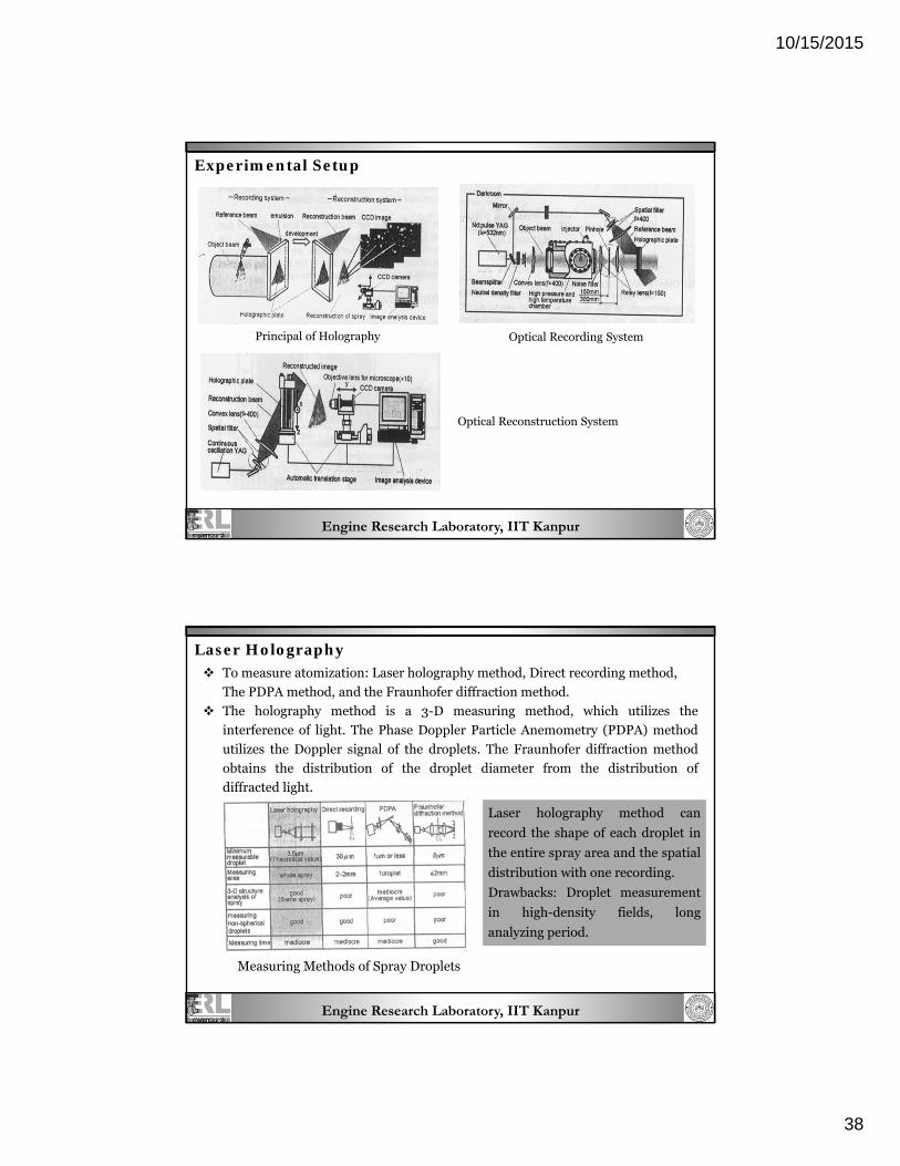
Experimental Setup
Optical Recording System
Optical Reconstruction System
Principal of Holography
Engine Research Laboratory, IIT Kanpur
Laser Holography To measure atomization: Laser holography method, Direct recording method,
The PDPA method, and the Fraunhofer diffraction method.
The holography method is a 3-D measuring method, which utilizes the
interference of light. The Phase Doppler Particle Anemometry (PDPA) method
utilizes the Doppler signal of the droplets. The Fraunhofer diffraction method
obtains the distribution of the droplet diameter from the distribution of
diffracted light.
Laser holography method can
record the shape of each droplet in
the entire spray area and the spatial
distribution with one recording.
Drawbacks: Droplet measurement
in high-density fields, long
analyzing period.
Measuring Methods of Spray Droplets
10/15/2015
39
Engine Research Laboratory, IIT Kanpur
Laser Doppler Velocimetry (LDV)
Engine Research Laboratory, IIT Kanpur
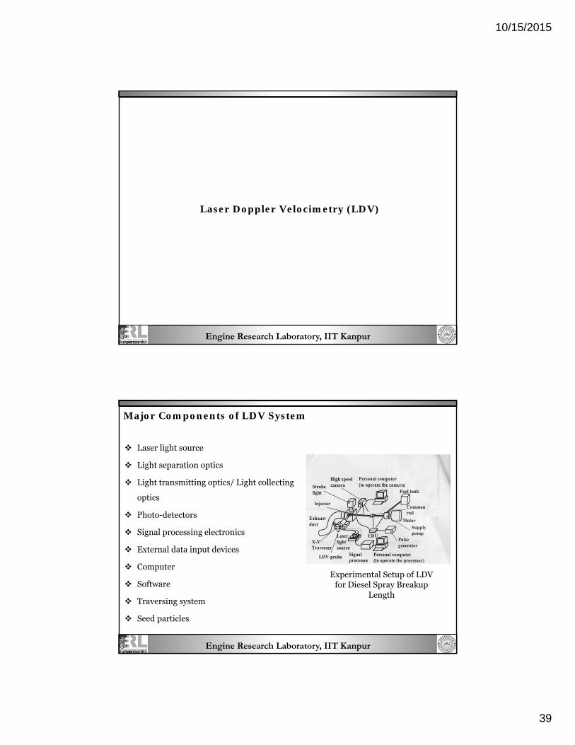
Laser light source
Light separation optics
Light transmitting optics/ Light collecting
optics
Photo-detectors
Signal processing electronics
External data input devices
Computer
Software
Traversing system
Seed particles
Experimental Setup of LDV for Diesel Spray Breakup
Length
Major Components of LDV System
10/15/2015
40
Engine Research Laboratory, IIT Kanpur
Laser Doppler Velocimetry (LDV) Data at a single point. Offers flexibility. It works in air or water. As micron-sized particles entrained
in a fluid pass through the intersection of two laser beams, the scattered light received from the particles fluctuates in intensity.
The frequency of this fluctuation is equivalent to the Doppler shift between the incident and scattered light, and is thus proportional to the component of particle velocity.
The velocity direction can be fixed if one of the laser beams has a frequency slightly different from that of the other.
The frequency is measured using digital computers or photon correlators or spectral analyzers.
Applications: Measurements of rotor tip vortices using three-component Laser Doppler Velocimetry. LDV measurements in a boundary layer. Survey of a wake field. Measurements in a shock tube flow. Measurement of Diesel Spray Breakup Length
Diesel spray characteristics by laser Doppler signals: Spray tip penetration and spray breakup length are simply obtained by measuring the delay time of Doppler signals from injection start to spray tip arrival at each measuring point. Spray breakup length is estimated by measuring the standard deviation of the delay time of Doppler signals, which indicates dispersion of the time from injection start to Doppler signal rising.
Engine Research Laboratory, IIT Kanpur
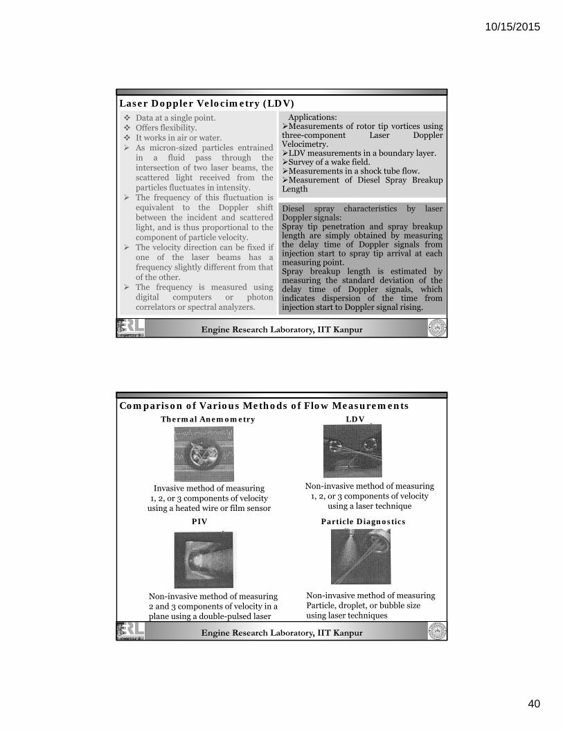
Thermal Anemometry
Invasive method of measuring 1, 2, or 3 components of velocity
using a heated wire or film sensor
LDV
Non-invasive method of measuring 1, 2, or 3 components of velocity
using a laser technique
PIV
Non-invasive method of measuring 2 and 3 components of velocity in a plane using a double-pulsed laser
Particle Diagnostics
Non-invasive method of measuring Particle, droplet, or bubble size using laser techniques
Comparison of Various Methods of Flow Measurements