1 B. Cros, JUAS 2012 1 Laser driven plasma wakefield: progation effects Laser driven plasma wakefield: progation effects Brigitte Cros Laboratoire de Physique des Gaz et des Plasmas CNRS-Université Paris Sud, Orsay, France Propagation effects play an important role in LPA Propagation effects play an important role in LPA The ultra-high intensity required fo laser wakefield is usually achieved inside a small volume Acceleration of electrons to ultra-high energies requires to maintain a high acceleration gradient over a long distance Ultra-intense laser beams interact with matter and give rise to non linear effects, which usually grow with propagation distance B. Cros, CAS November 2014 2
Transcript
1
B. Cros, JUAS 2012 1
Laser driven plasma wakefield: progation effects
Laser driven plasma wakefield: progation effects
Brigitte CrosLaboratoire de Physique des Gaz et des Plasmas
CNRS-Université Paris Sud, Orsay, France
Propagation effects play an important role in LPA
Propagation effects play an important role in LPA
The ultra-high intensity required fo laser wakefield isusually achieved inside a small volume
Acceleration of electrons to ultra-high energiesrequires to maintain a high acceleration gradient over a long distance
Ultra-intense laser beams interact with matter and give rise to non linear effects, which usually grow withpropagation distance
B. Cros, CAS November 2014 2
2
OutlineOutline
B. Cros, CAS November 2014 3
Laser plasma acceleration characteristics (reminder)Description of laser and plasma wave
Electron acceleration parameters
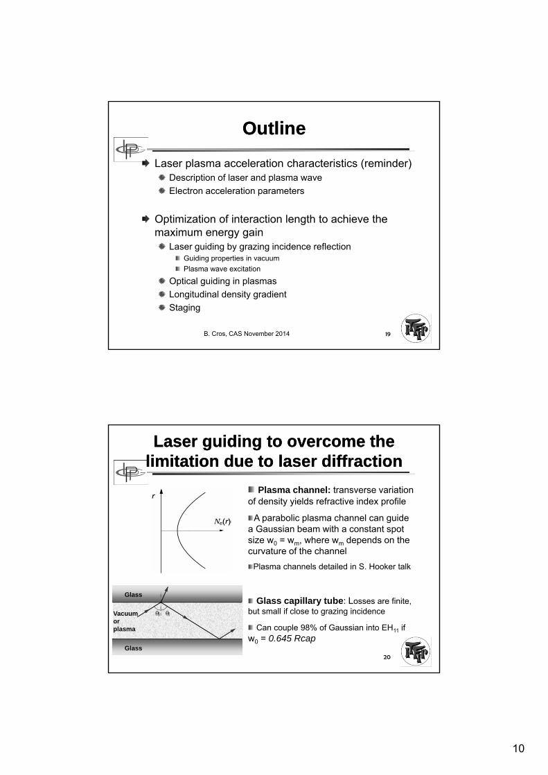
Optimization of interaction length to achieve the maximum energy gain
Laser guiding by grazing incidence reflectionGuiding properties
Plasma wave excitation
Optical guiding in plasmas
Longitudinal density gradient
Staging
Laser propagation in vacuumLaser propagation in vacuum
Ultra High Intensity, larger than ~1018 W/cm²
The beam has to be focused w0
Typical volume small w0²ZR ~10µmx10µmx300µm
B. Cros, CAS November 2014 4
3
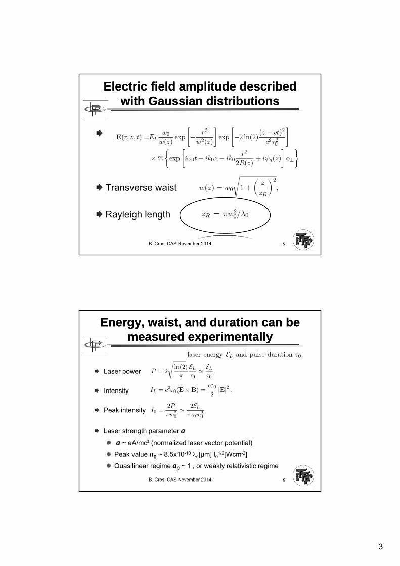
Electric field amplitude described with Gaussian distributions
Electric field amplitude described with Gaussian distributions
Transverse waist
Rayleigh length
B. Cros, CAS November 2014 5
Energy, waist, and duration can be measured experimentally
Energy, waist, and duration can be measured experimentally
Laser power
Intensity
Peak intensity
Laser strength parameter a
a ~ eA/mc² (normalized laser vector potential)
Peak value a0 ~ 8.5x10⁻¹⁰ [µm] I01/2[Wcm-2]
Quasilinear regime a0 ~ 1 , or weakly relativistic regime
B. Cros, CAS November 2014 6
4
Example of energy distribution in the focal plane
Example of energy distribution in the focal plane
UHI beam with adaptative correction
Grey area = 84 % of energy in the focal plane
Good beam quality in the focal plane
B. Cros, CAS November 2014 7Ju et al., Phys. Plasmas 20, 083106 (2013)
The plasma is used as a transformerThe plasma is used as a transformer
Single electrons wiggle in the transverse laser field
In a plasma, the action of the ponderomotive force leads to a plasma wave (time average)
B. Cros, CAS November 2014 8
k0
E
B
kp
Ep
For IL~1018W/cm², |E| ~ 1012V/m: why don’t we use the laser field directly?
5
B. Cros, JUAS 2012 9
Longitudinal electric field associated to a plasma wave
Longitudinal electric field associated to a plasma wave
Accelerating fields > 100 GV/m
ne = Zni
ne +dne
ESpace charge fieldPlasma wavelength
p[µm] ~33 (ne[1018cm-3])1/2
v
x
E
p
Relativistic wave:
phase velocity of the order of the laser group velocity
B. Cros, JUAS 2012 10
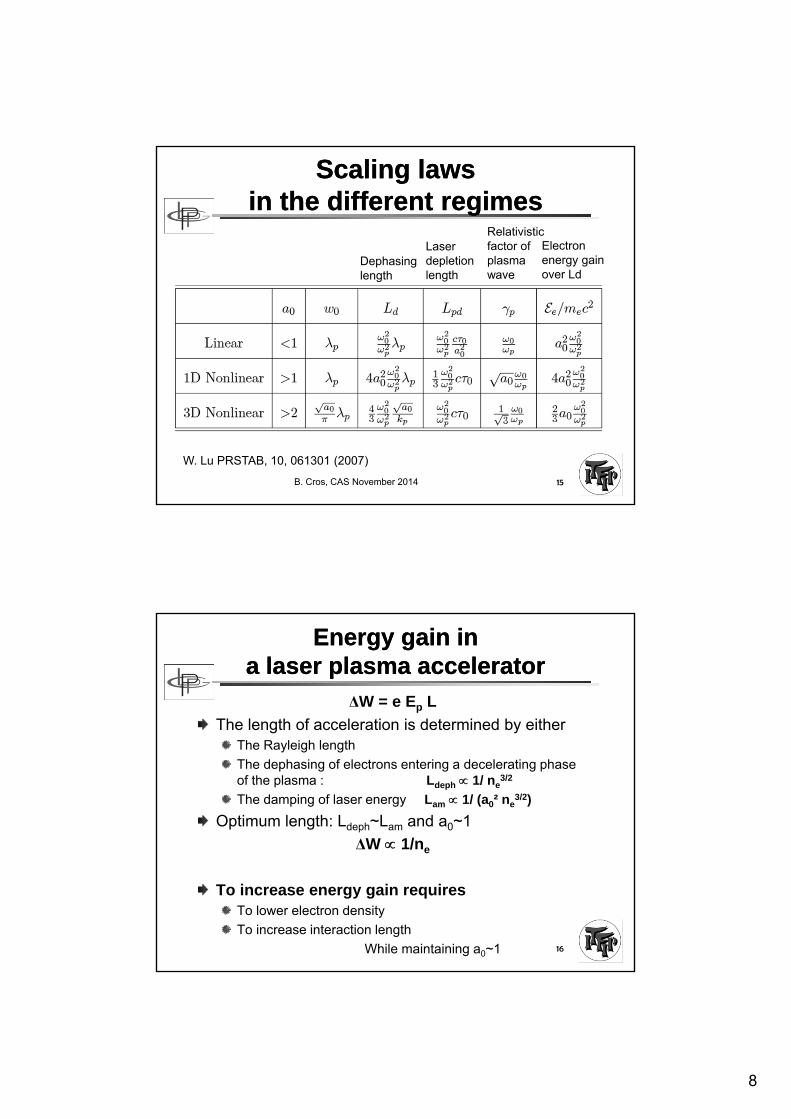
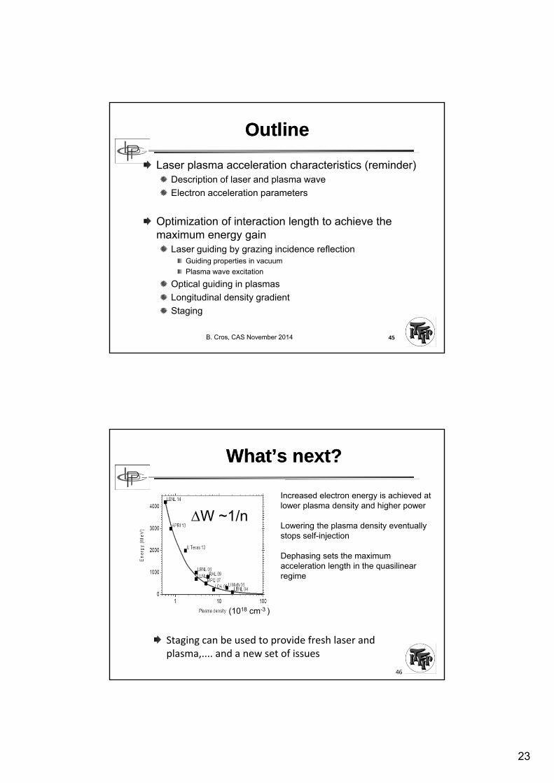
Dephasing length for accelerated electrons Dephasing length for accelerated electrons
Energy gain
W = e Ep La
= p / 0
Ep t1 t2 t3v~c
v~cLa < Ldeph = p 2
ne 1017cm-3 1019cm-3
100 10
La 1 m 1 mm
Wmax 20 GeV 200 MeV
W ~ ne-1
Ep ~ ne1/2
La ~ ne-3/2
6
Linear vs NL regime of LPALinear vs NL regime of LPA
2 main regimes:quasilinear regime
bubble or blowout regime
B. Cros, CAS November 2014 11
a =
Importance of transverse structure to define these regimes
Challenges for a multi-stage LPAChallenges for a multi-stage LPA
Improve the performance of laser systems:Beam quality, reliability , stability
Average power (10Hz à 10kHz)
Plasma stages in the quasi linear regime to control transverse and longitudinal fields:
provides control of beam dynamics
electron or positron beams
meter scale plasma sources need to be developped at lowdensity
External injection schemesbeam transport and shaping need to be developped for electron and laser beams
Design through European collaboration
25
The preservation of a high average gradient requires compact laser coupling
The preservation of a high average gradient requires compact laser coupling
The large power (~PW) and large spot (~100µm) require several meters to focus laser beams into plasma stages:
Plasma mirrors are promising schemes for compact coupling
Currently used for temporal contrast improvement
Innovative, high repetition rate schemes are beingdevelopped (metallic tape or liquid jet)
B. Cros, CAS November 2014 49
Plasma creationne>ncreflecting plasma
G. Doumy et al., Phys. Rev. E ,2004
Transparent medium
Plasmas mirrors :ultra –fast optical switchesCourtesy of P. Monot, CEA-Saclay
BV
BC
The pedestal goes throughthe transparent medium
10 eV1 eV
Multiphotonic absorption or tunnel effect + avalanche
BV
BC
26
B. Cros, JUAS 2012 51
SummarySummary
LPA currently produce electron bunches of extremely short duration (<10fs), up to several GeV, achieved by operationat lower densityLaser guiding and increased laser energy should produceelectron bunches in the ~10 GeV range in one stage (ex: BELLA project in the USA or APOLLON 10 PW in France)Staging is the next milestone for the development of LPA
Very active and motivating field of research:involving laser, plasma and accelerator physics, several facilites under development, need for students, researchers and engineers