11
1 LASER RANGEFINDER BINOCULAR

1111
LASER RANGEFINDER BINOCULARHDHDHD
2
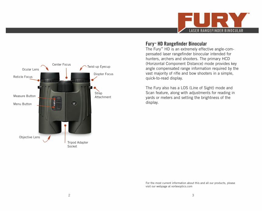
Fury™ HD Rangefi nder BinocularThe Fury™ HD is an extremely effective angle-com-pensated laser rangefi nder binocular intended for hunters, archers and shooters. The primary HCD (Horizontal Component Distance) mode provides key angle compensated range information required by the vast majority of rifl e and bow shooters in a simple, quick-to-read display.
The Fury also has a LOS (Line of Sight) mode and Scan feature, along with adjustments for reading in yards or meters and setting the brightness of the display.
3
Ocular Lens
Center FocusTwist-up Eyecup
Strap Attachment
Reticle FocusDiopter Focus
Measure Button
Menu Button
Tripod Adapter Socket
Objective Lens
For the most current information about this and all our products, please visit our webpage at vortexoptics.com
4 5
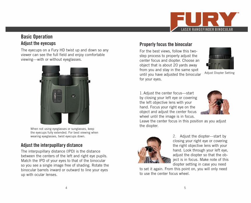
The eyecups on a Fury HD twist up and down so any viewer can see the full fi eld and enjoy comfortable viewing—with or without eyeglasses.
When not using eyeglasses or sunglasses, keep the eyecups fully extended. For best viewing when wearing eyeglasses, twist eyecups down.
Adjust the interpupillary distanceThe interpupillary distance (IPD) is the distance between the centers of the left and right eye pupils. Match the IPD of your eyes to that of the binocular so you see a single image free of shading. Rotate the binocular barrels inward or outward to line your eyes up with ocular lenses.
Basic OperationAdjust the eyecups Properly focus the binocular
For the best views, follow this two-step process to properly adjust the center focus and diopter. Choose an object that is about 20 yards away from you and stay in the same spot until you have adjusted the binocular for your eyes.
1. Adjust the center focus—start by closing your left eye or covering the left objective lens with your hand. Focus your right eye on the object and adjust the center focus wheel until the image is in focus. Leave the center focus in this position as you adjust the diopter.
2. Adjust the diopter—start by closing your right eye or covering the right objective lens with your hand. Look through your left eye, adjust the diopter so that the ob-ject is in focus. Make note of this diopter setting in case you need
to set it again. From this point on, you will only need to use the center focus wheel.
Adjust Diopter Setting
6 7
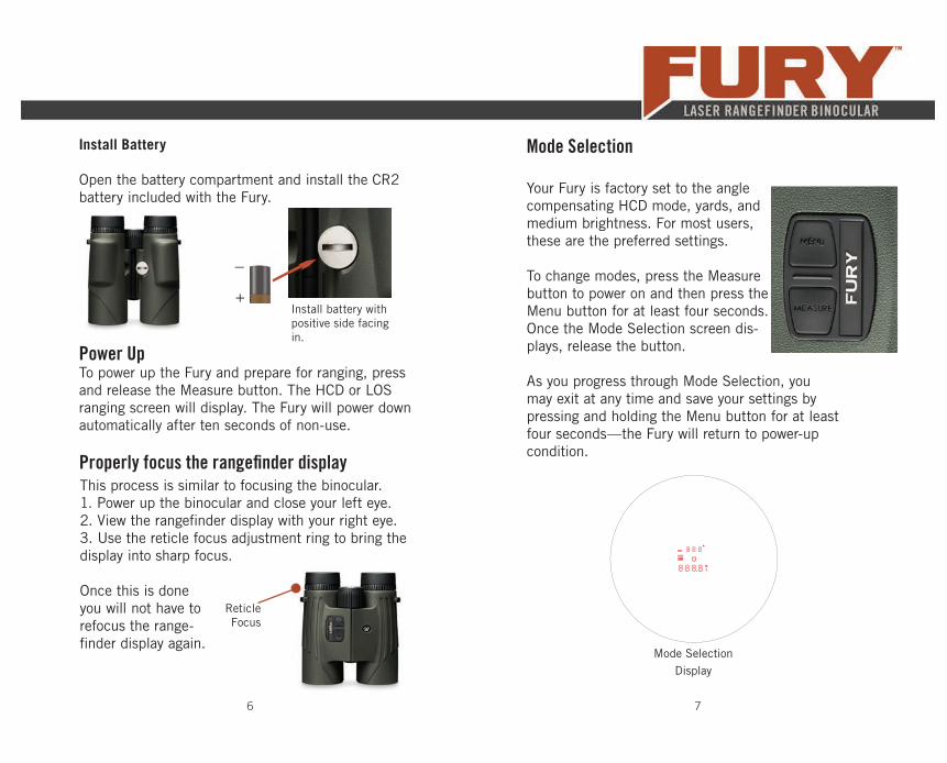
Install Battery
Open the battery compartment and install the CR2 battery included with the Fury.
Install battery with positive side facing in.
+
–
Power UpTo power up the Fury and prepare for ranging, press and release the Measure button. The HCD or LOS ranging screen will display. The Fury will power down automatically after ten seconds of non-use.
Mode Selection
Your Fury is factory set to the angle compensating HCD mode, yards, and medium brightness. For most users, these are the preferred settings.
To change modes, press the Measure button to power on and then press the Menu button for at least four seconds. Once the Mode Selection screen dis-plays, release the button.
As you progress through Mode Selection, you may exit at any time and save your settings by pressing and holding the Menu button for at least four seconds—the Fury will return to power-up condition.
Mode SelectionDisplay
Properly focus the rangefi nder displayThis process is similar to focusing the binocular. 1. Power up the binocular and close your left eye.2. View the rangefi nder display with your right eye.3. Use the reticle focus adjustment ring to bring the display into sharp focus.
Once this is done you will not have to refocus the range-fi nder display again.
Reticle Focus
8 9
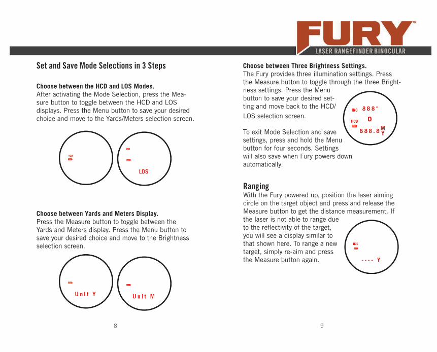
Set and Save Mode Selections in 3 Steps
Choose between the HCD and LOS Modes.After activating the Mode Selection, press the Mea-sure button to toggle between the HCD and LOS displays. Press the Menu button to save your desired choice and move to the Yards/Meters selection screen.
Choose between Yards and Meters Display.Press the Measure button to toggle between the Yards and Meters display. Press the Menu button to save your desired choice and move to the Brightness selection screen.
To exit Mode Selection and save settings, press and hold the Menu button for four seconds. Settings will also save when Fury powers down automatically.
Choose between Three Brightness Settings.The Fury provides three illumination settings. Press the Measure button to toggle through the three Bright-ness settings. Press the Menu button to save your desired set-ting and move back to the HCD/LOS selection screen.
RangingWith the Fury powered up, position the laser aiming circle on the target object and press and release the Measure button to get the distance measurement. If the laser is not able to range due to the refl ectivity of the target, you will see a display similar to that shown here. To range a new target, simply re-aim and press the Measure button again.
10 11
Scan RangingActivate Scan Ranging by pressing and holding the Measure button down.
Keeping the button depressed will continuously mea-sure distance as you pan back and forth across target objects. The aiming circle will blink as you pan.Releasing the Measure button will return laser to the Power Up Condition.
Ranging Mode ExplanationsThe Fury provides two range modes: HCD (Horizontal Component Distance) and LOS (Line of Sight). Both modes offer a Scan feature.
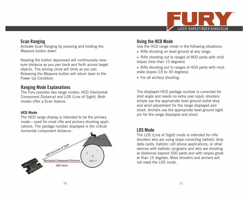
HCD ModeThe HCD range display is intended to be the primary mode—used for most rifl e and archery shooting appli-cations. The yardage number displayed is the critical horizontal component distance.
500 Yard Line of Sight
Horizontal Component Distance
385 Yards
Using the HCD ModeUse the HCD range mode in the following situations: • Rifl e shooting on level ground at any range.
• Rifl e shooting out to ranges of 800 yards with mild slopes (less than 15 degrees).
• Rifl e shooting out to ranges of 400 yards with mod-erate slopes (15 to 30 degrees).
• For all archery shooting.
The displayed HCD yardage number is corrected for shot angle and needs no extra user input; shooters simply use the appropriate level ground bullet drop and wind adjustment for the range displayed and shoot. Archers use the appropriate level ground sight pin for the range displayed and shoot.
LOS ModeThe LOS (Line of Sight) mode is intended for rifl e shooters who are using slope correcting ballistic drop data cards, ballistic cell phone applications, or other devices with ballistic programs and who are shooting at distances beyond 500 yards and with slopes great-er than 15 degrees. Most shooters and archers will not need the LOS mode.
12 13
The range number displayed in LOS mode is the actual line of sight range with no ballistic correction for slope. Most of the commonly used ballistic devices can provide independent slope correction for bullet drop data and require actual line of sight range input. Using the LOS range when calculating bullet wind drifts under these steep slope/long range conditions will provide a higher degree of accuracy than using the HCD range.
To use, simply input the LOS range number into the electronic device or use the LOS range when referenc-ing ballistic drop cards with slope correction.
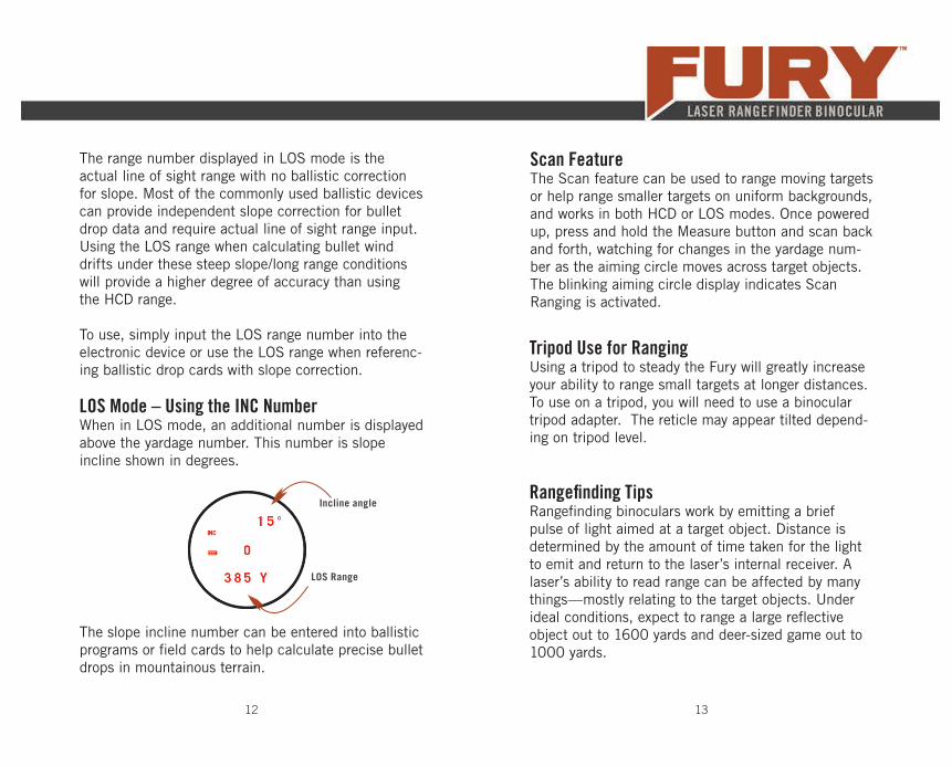
LOS Range
Incline angle
LOS Mode – Using the INC NumberWhen in LOS mode, an additional number is displayed above the yardage number. This number is slope incline shown in degrees.
The slope incline number can be entered into ballistic programs or fi eld cards to help calculate precise bullet drops in mountainous terrain.
Scan FeatureThe Scan feature can be used to range moving targets or help range smaller targets on uniform backgrounds, and works in both HCD or LOS modes. Once powered up, press and hold the Measure button and scan back and forth, watching for changes in the yardage num-ber as the aiming circle moves across target objects. The blinking aiming circle display indicates Scan Ranging is activated.
Tripod Use for RangingUsing a tripod to steady the Fury will greatly increase your ability to range small targets at longer distances. To use on a tripod, you will need to use a binocular tripod adapter. The reticle may appear tilted depend-ing on tripod level.
Rangefi nding TipsRangefi nding binoculars work by emitting a brief pulse of light aimed at a target object. Distance is determined by the amount of time taken for the light to emit and return to the laser’s internal receiver. A laser’s ability to read range can be affected by many things—mostly relating to the target objects. Under ideal conditions, expect to range a large refl ective object out to 1600 yards and deer-sized game out to 1000 yards.
14 15
Laser Performance Tips• Light colors will usually refl ect the laser pulse
better than dark ones. An exception would be snow, which can be diffi cult to range.
• Shiny, refl ective surfaces will usually refl ect the laser pulse better than dull, textured surfaces. Animal hair will not refl ect as well as a hard sur-face.
• Ranging while under cloud cover can improve laser performance compared to ranging while under bright sunny conditions.
• Solid objects, such as rock piles, will refl ect the laser pulse better than less dense items such as bushes.
• Flat surfaces perpendicular to the laser pulse will refl ect better than curved surfaces or surfaces angled in relation to laser pulse.
• Ranging over water can sometimes cause false refl ections and readings.
• At longer distances, larger objects will be easier to range than small objects.
• If you are having diffi culty ranging an animal or object, try ranging a different nearby object or use the Scan feature to pan back and forth while watching for changes in range number.
A rainguard for the ocular lenses and tethered ob-jective lens covers is included. Use these covers to protect the lenses whenever you are not viewing.
Lens Covers
The protective case provides safe storage between viewing sessions. The carry strap is already attached to the case.
Carry Case
Accessories
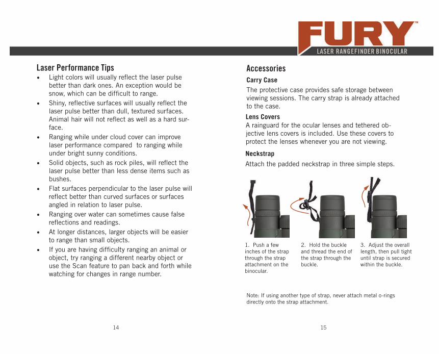
Attach the padded neckstrap in three simple steps.
Neckstrap
1. Push a few inches of the strap through the strap attachment on the binocular.
3. Adjust the overall length, then pull tight until strap is secured within the buckle.
2. Hold the buckle and thread the end of the strap through the buckle.
Note: If using another type of strap, never attach metal o-rings directly onto the strap attachment.
17
Caution: Binoculars are not intended for looking at the sun, or any other intense light source. Such viewing could damage the retina and cornea of your eyes—even to the point of causing blindness.
Lens CareMaintain the optical brilliance of the binocular by keep-ing lens surfaces free of dirt, oils, and dust. Make use of the provided eyepiece and objective lens covers to protect the lenses when not viewing. Then, store in its carry case between viewing sessions.
In order to enjoy the best views through your binocular, take time to regularly clean the exterior lenses:
1. Remove any dust or grit from lenses before wiping. Use a can of pressurized air, soft camel hair brush, or an acrylic optical brush.
2. Clear lenses of smudges, fi ngerprints, or eyelash oil. Fog the lenses with your own breath, then use a non-abrasive lens cloth to clean the lenses. Alternately, use a lens cleaning fl uid and optical paper to clean lenses.
16
Safety and PrecautionsDo not stare into beam or view directly without laser eye protection. Staring continuously into beam for pro-longed periods of time could cause harm to your eyes. If used properly, this device is safe for your eyes and laser eye protection is not needed. • Use the correct battery (CR2) and proper battery orientation.
• Do not look at sun.
• Do not activate Menu or Measure buttons while aiming at eye or looking into objective lens.
• Do not disassemble.
• Do not allow children to play with unit.
CAUTION—Use of controls or adjustments or performance of procedures other than those specifi ed herein may result in hazardous radiation exposure.
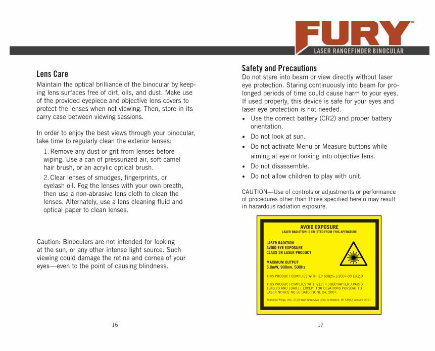
AVOID EXPOSURELASER RADIATION IS EMITTED FROM THIS APERATURE
LASER RADITIONAVOID EYE EXPOSURECLASS 3R LASER PRODUCT
MAXIMUM OUTPUT5.0mW, 900nm, 500Hz
THIS PRODUCT COMPLIES WITH IEC 60825-1:2007-03 Ed.2.0
THIS PRODUCT CIMPLIES WITH 21CFR SUBCHAPTER J PARTS 1040.10 AND 1040.11 EXCEPT FOR DEVATIONS PURSUAT TO LASER NOTICE NO.50 DATED JUNE 24, 2007.
Sheltered Wings, INC. 2120 West Greenview Drive, Middleton, WI 53562 January, 2017
18 19
The VIP WarrantyWe build optics based on our commitment to your absolute satisfaction. That’s why Vortex products are unconditionally guaranteed. We make this Very Important Promise to you—a Very Important Person.
Rest assured that in the event your binocular becomes damaged or defective, Vortex Optics will re-pair or replace the binocular at no charge to you. Call Vortex Optics at 800-426-0048 for prompt, professional, and friendly service.
Vortex Optics2120 West Greenview DriveMiddleton, WI [email protected]
Visit vortexoptics.com for more information. Canadian customers may visit vortexcanada.net for customer service information.
The VIP Warranty does not cover loss, theft, deliberate damage, or cosmetic damage that does not hinder the performance of the product.
FCC RequirementsThe user’s manual or instruction manual for an intentional or unin-tentional radiator shall caution the user that changes or modifi ca-tions not expressly approved by the party responsible for compli-ance could void the user’s authority to operate the equipment.
Note: This equipment has been tested and found to comply with the limits for a Class B digital device, pursuant to part 15 of the FCC Rules. These limits are designed to provide reasonable pro-tection against harmful interference in a residential installation. This equipment generates, uses and can radiate radio frequency energy and, if not installed and used in accordance with the instructions, may cause harmful interference to radio communi-cations. However, there is no guarantee that interference will not occur in a particular installation. If this equipment does cause harmful interference to radio or television reception, which can be determined by turning the equipment off and on, the user is encouraged to try to correct the interference by one or more of the following measures:
• Reorient or relocate the receiving antenna.• Increase the separation between the equipment and receiver.• Connect the equipment into an outlet on a circuit different from that to which the receiver is connected.• Consult the dealer or an experienced radio/TV technician for help.

LRF-300-16


