Cost efficient design Operates in full sunlight Low power consumption Wide field of view Small footprint Simple serial connectivity Long Range This device contains a component which emits laser radiation. The laser product is designated Class 1 during all operating modes. This means that the laser is safe to look at with the unaided eye, however it is advisable to not look directly into the beam when in use. Rev Date Changes 0.9 12/19/2016 Initial Release Laser Safety ........................................................ 0 Documentation Revision Information...............0 Specifications ..................................................... 1 Dimensions ....................................................... 1 Physical ............................................................. 1 Electrical ............................................................ 1 Measurement Performance .............................. 1 Field of View ..................................................... 1 Measurement Error Test Data .......................... 1 Overview of Interfaces ....................................... 2 Connector ......................................................... 2 Mounting and Vibration Considerations ............ 2 Mounting Features and Orientation .................3 Ingress Protection Rating ..................................3 Enclosure Window Design ................................ 3 Theory of Operation ........................................... 3 Distance Measurement .....................................3 Angle Measurement .........................................3 Applications ....................................................... 3 Internal Filters .................................................... 4 Visualizer Overview ........................................... 4 Serial Protocol Specification ............................... 4 Data Encoding and Decoding ............................ 4 Communication Format ....................................4 Available Command Codes ................................. 4 General Communication Packet Structure.......... 5 Definition of terms: ...........................................5 DS - Start data acquisition .................................5 DX - Stop data acquisition .................................6 MS - Adjust Motor Speed ..................................6 MI - Motor Information ....................................6 IV - Version Details ............................................7 ID - Device Info ..................................................7 RR - Reset Device ..............................................7 CAUTION sweep v1.0
Transcript
Cost efficient design
Operates in full sunlight
Low power consumption
Wide field of view
Small footprint
Simple serial connectivity
Long Range
This device contains a component which emits laser radiation. The laser product is designated Class 1 during all operating modes. This means that the laser is safe to look at with the unaided eye, however it is advisable to not look directly into the beam when in use.
ALL DIMENSIONS ARE IN MM, DRAWINGS ARE NOT TO SCALE
Figure 1, Sweep Dimension Drawing
Specification Value
Weight 120 g (4.23 oz.)
Operating Temperature -20 to 60° C (-4 to 140°F)
Storage Temperature -40 to 80° C (-40 to 176°F)
Specification Value
Power 5VDC ±0.5Vdc
Current Consumption Up to 650mA 450mA nominal
Specification Value
Range (75% reflective target)
40 m (131ft)
Resolution 1 cm (0.4 in)
Update Rate (75% reflective target)
Up to 1075Hz (see “Theory of Operation”)
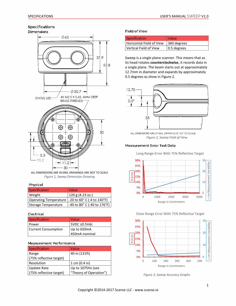
Sweep is a single plane scanner. This means that as its head rotates counterclockwise, it records data in a single plane. The beam starts out at approximately 12.7mm in diameter and expands by approximately 0.5 degrees as show in Figure 2.
Sweep can be connected to low level micro controllers directly using its serial port, or to a PC using the provided USB to serial converter.
Figure 4, Sweep Cable Diagram
Sweep has two serial port connectors with identical signals. This allows for more mounting options.
Figure 5, Sweep Pigtail Cable Connector Detail
Pin Color Function
1 Red 5 Vdc (+) (minimum 0.5A capable)
2 Orange Power enable (internal pull-up)
3 Yellow Sync/Device Ready
4 Green UART RX 3.3V (5V compatible)
5 Blue UART TX 3.3V (5V compatible)
6 Black Ground (-)
You can create your own cable if needed for your application. These components are readily available.
Part Description Mfg. Part No.
Connector Housing
6-Position, rectangular housing, latch-lock connector receptacle with 1.25 mm (0.049 in.) pitch.
JST GHR-06V-S
Connector terminal
26-30 AWG crimp socket connector
JST SSHL-002T-P0.2
Wire UL 1061 26 AWG stranded copper
N/A N/A
Sweep can be mounted in any orientation. Sweep’s rotating head is dynamically balanced, which means it is immune to linear vibration, but it can be affected by rotational vibration. Sudden rotational shocks can cause the head to either slow down or speed up, which can affect data accuracy. If Sweep is rotationally jerked hard enough, it can cause the motor to lose sync, which will trigger a momentary motor pause, and then restart.
Sweep has four brass threaded inserts designed to fit M2.5X0.45 screws in its base. These are the best features for mounting Sweep to an application. The screw holes are aligned with the scanner’s measurement angles. The scanner’s zero degree starting angle is aligned with the status LED, as shown in Figure 7.
Sweep is rated as IP51, which is to say, it is not dust or water tight. It is recommended that Sweep be placed inside a protective transparent enclosure if it will be used in dusty or wet environments.
Figure 7, Sweep Mounting Features (all dimensions in mm)
Sweep uses 905nm laser light, which passes through several kinds of clear glass and plastic very well. Based on our testing, clear Polycarbonate plastic is one of the best choices, as it can be molded to fit the profile of the application’s enclosure, is very inexpensive, and in most cases, is more than 95% translucent to Sweep’s light beam. Factors that can affect the performance of a window are:
Thickness of the window. Thicker windows will block more light, as well as bend the light more if the beam is not hitting the window normal to the surface.
Scratches and dust. The presence of scratches and dust on the window will scatter the laser light, and may reflect some of the light back into the sensor’s detector, causing measurement errors.
Surface coatings. There are a variety of coatings that can help with the performance of windows. One is an anti-reflective (AR) coating, which can help reduce the amount of laser light that is reflected as it passes through the window’s surface.
Sweep employs a time of flight ranging method. This technique involves transmitting a packet of micro pulses of light in a unique pattern. When this light bounces off an object and returns to the receiving detector, a correlation algorithm is used to identify the unique light pattern from ambient noise. Each light packet is different from the last, which allows multiple Sweep sensors to operate adjacent to each other without interference. The light packets that Sweep uses can vary, which can affect accuracy of range measurements, as well as the maximum range and update rate. Under normal operation, Sweep limits the maximum time per measurement to around 1ms. Sometimes if not enough light is returned from the environment, the measurement fails, and a 1 is returned as the range value. On the other hand, if allot of light is returned from the environment, the correlation algorithm can reach its maximum accuracy early, and can return a range value in less than 1ms. This is what makes the update rate of Sweep variable.
Sweep uses an optical encoder to measure the angle of the rotating sensor head. The angle that is recorded for a range data point is the angle the sensor is at when the measurement is completed.
Sweep can be used for a variety of applications, including robot guidance/obstacle avoidance, 3D scanning, surveying, people tracking and many more.
Sweep has the ability to perform some simple data filtering within the sensor itself. These filters are still in development, and are being made for specific customer segments. Examples include having Sweep split up its field of view into eight sections, then transmit only the closest objects within each of those sectors. Another example is to have Sweep only output data from a range of angles. If you have an application that requires a specific filter, please contact us.
You can download the Sweep visualizer at www.scanse.io/downloads The purpose of the Scanse visualizer is to provide a way to quickly evaluate Sweep’s performance in your application/environment. For some applications, like surveying, our visualizer can be used to take quick measurements between range data points within a scan. It contains a programming tool for updating Sweep’s firmware. A full tutorial for using the visualizer can be found in software support section at support.scanse.io.
Specification Value
Bit Rate 115.2 Kbps
Parity None
Data Bit 8
Stop Bit 1
Flow Control None
All characters used for commands and responses are ASCII code in addition to CR and LF, except for the measurement packet. Responses with float values are sent as 16bit integer values. Example conversion: angle_f = 1.0f * ((float)(angle_i >> 4) + ((angle_i & 15) / 16.0f));
All communication packets between the host computer and the sensor begin with ASCII letter command codes.
Example: DS, DX, MS, MI, IV… Line Feed (LF) or Carriage Return (CR)
or Command with parameter
Command Symbol (2 bytes)
Parameter (2 bytes)
Line Feed (LF)
(SENSOR -> HOST) Response with no parameter echoed
Command Symbol (2 bytes)
Status (2 bytes)
Sum of Status Line Feed (LF)
or Command with parameter echoed
Command Symbol (2 bytes)
Parameter (2 bytes)
Line Feed (LF)
Status (2 bytes)
Sum of Status Line Feed (LF)
Command Symbol: 2 byte code at the beginning of every command. Parameter: Information that is needed to change sensor settings. Line Feed (LF) or Carriage Return (CR): Terminating code. Command can have LF or CR or both as termination code but reply will always have LF as its termination code. Status: 2 bytes of data in reply that informs normal processing if command is authenticated or errors if undefined, invalid or incomplete command is received by sensor. Status other than 00 and 99 are error codes. Sum of Status: 1 byte of data used in authentication. Calculated by adding status bytes, taking lower 6 byte of this sum and adding 30H to this sum. Sum = 111111 = 3fH+30H = 6fH = o Example: [LF] 0 0 [LF] = P Responses to Invalid Commands: 11 -- Invalid parameter
Initiates scanning
Responds with header containing status.
Next responds with measurement packets indefinitely until commanded to stop. (HOST -> SENSOR)
sync / error: 0 bit indicates the sync value, a value of 1 indicates the packet is the beginning of a new scan, a value of 0 indicates all other measurement packets. Bits 1-6 are reserved for error codes. azimuth: Angle that ranging was recorded at. Azimuth is a float value - needs to be converted from 16bit int to float, use instructions at the top distance: Distance of range measurement. signal strength: Signal strength of current ranging measurement. Larger is better. Range: 0-255 checksum: Calculated by adding the 6 bytes of data then dividing by 255 and keeping the remainder. (Sum of bytes 0-6) % 255 Status 00 -- Command received without any Error 22 -- Stopped to verify error 55 -- Hardware trouble 99 -- Resuming operation
Default Speed: Sensor stores last speed command in non-volatile memory, and will return to that speed after a power cycle, except if the last state was speed 00 (stopped). (HOST -> SENSOR)
M S Speed Parameter (2 bytes)
LF
Speed Parameter: 00 - 10 : 10 different speed levels according to revolutions per second (Hz), increments of 1. Example: 01,02,.. 00 = Motor stopped (SENSOR -> HOST)
M S Speed(Hz) (2 bytes)
LF Status Sum LF
Returns current rotation frequency in Hz in ASCII 00 - 10 (increments of 1) (HOST -> SENSOR)