22
LASER SCANS and VIDEO INSPECTION TECHNOLOGY COKE DRUMS TANKS CORRODED SURFACES

LASER SCANS and VIDEO INSPECTION TECHNOLOGY
COKE DRUMSTANKS
CORRODED SURFACES

Coke Drum Bulge Measurement
Scale ±4” with ½” color bands. Labels show spot deviation measurements

Laser Data Conversion / Comparison of Past Coke Drum Scans
2013 3D and 2D Laser Images

Depth / Height = Severity
Example: 1.5” Depth / 6.00” Height = 0.25 Severity. Note: Most severe rating would equal 1.00 (depth = height). Least severe would be 0.01.
Height
Depth
Bulge Severity Rating:
Export mesh or CAD files for FEA or other
Engineering Assessment

The IRISNDT Advantage Stabilized Tripod , Stabilized Suspended System
Repeatable
Photo Quality Hi-resolution
Distance Radial Measurements / Deviations Measurements
No Blind Spot Locations
Very Portable
Multiple Scans Can Be Performed To Avoid Blind Spots Due
To Obstructions
Quick ( 30 Minutes Per Scan Locations) Depending On Drum
Independent Of Owner Operator Assistance
Economical
3D Modeling of any Vessel, Tank, Column or Piece of Equipment
Requires Detailed Modeling Of Its Distortions
Supports Finite Element Analysis
Support Of API 510 And 653 For Inspections
Volumetric Measurement
Deformation Diagnostics Laser Scan
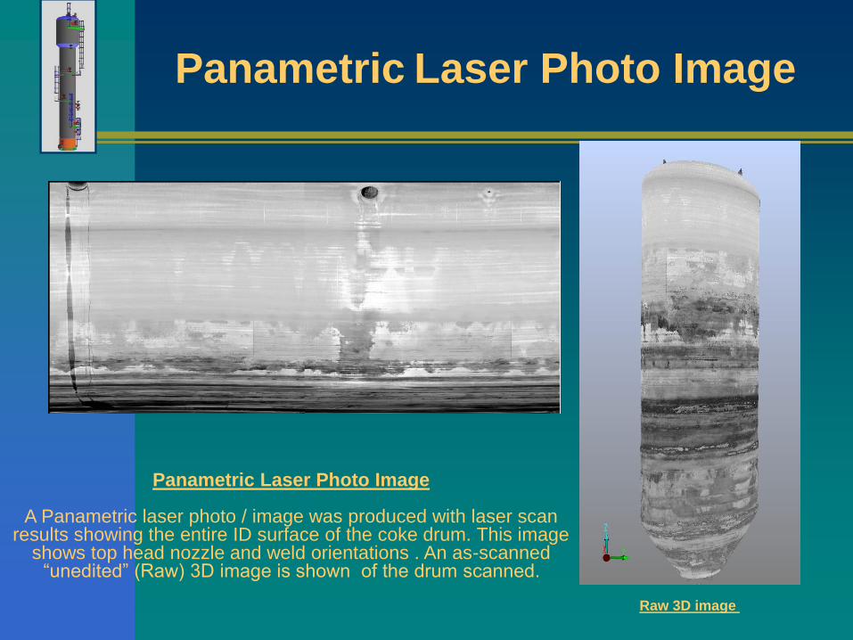
Panametric Laser Photo Image
Raw 3D image
Panametric Laser Photo Image
A Panametric laser photo / image was produced with laser scan results showing the entire ID surface of the coke drum. This image
shows top head nozzle and weld orientations . An as-scanned “unedited” (Raw) 3D image is shown of the drum scanned.

Tank External Laser Scan with Colour Imaging

Measurements: Tank Settlement, Diameter and Height MeasurementsMeasure Between Features, Nozzle or Pipe Diameter,
Measure between points
(can be multiple)

Measurements: Tank Settlement, Diameter and Height MeasurementsMeasure Between Features, Nozzle or Pipe Diameter,

3D Rendition of Floating Roof Tank Floor Scans

Tank Point to Point Measurements

Deviation Measurement Relative to a Standard Shape (Cylinder, Cone, Plane)
3D laser model of tank
Reference cylinder (nominal tank diameter)
Colour deviation map (actual dimensions vs nominal cylinder)
Deviation (colour) scale +50mm to -200mm (+2” to -8”)

Tank Cone Down Floor
Colour scale +50mm (edge) to -235 mm (centre). The object showing near the centre is part of the roof drain system
W
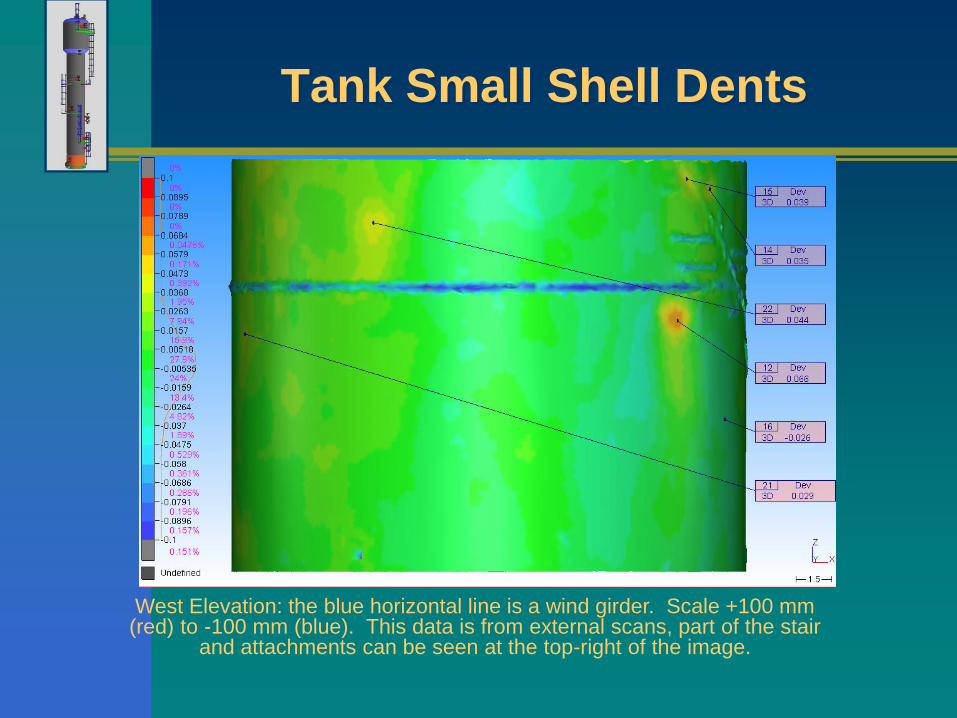
Tank Small Shell Dents
West Elevation: the blue horizontal line is a wind girder. Scale +100 mm (red) to -100 mm (blue). This data is from external scans, part of the stair
and attachments can be seen at the top-right of the image.
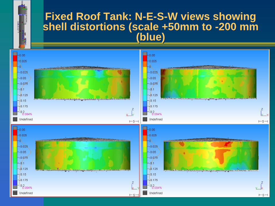
Fixed Roof Tank: N-E-S-W views showing shell distortions (scale +50mm to -200 mm
(blue)
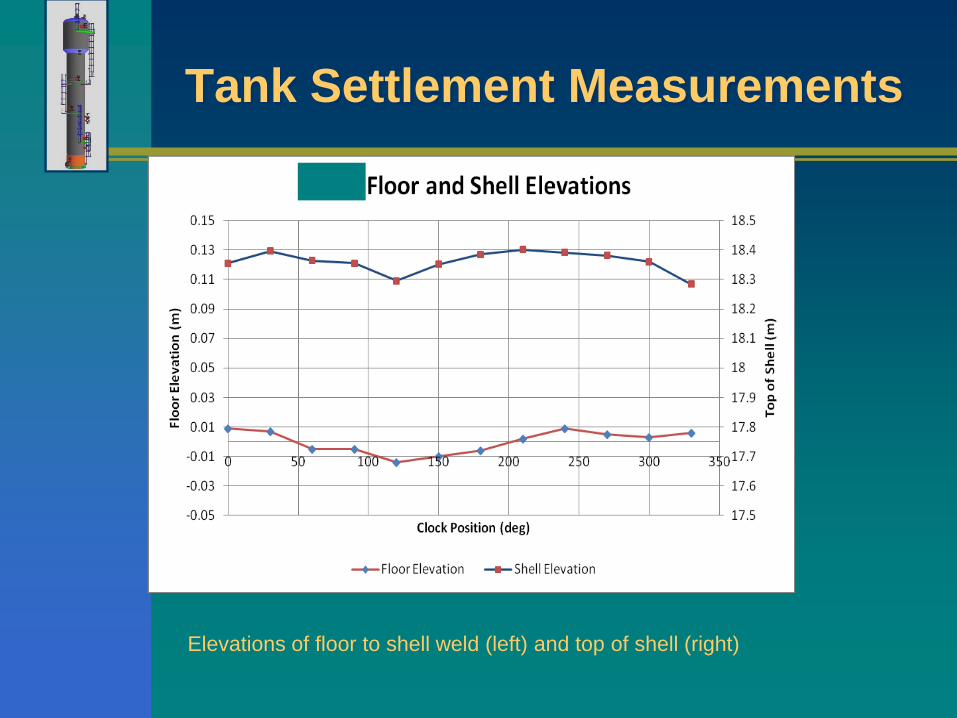
Tank Settlement Measurements
Elevations of floor to shell weld (left) and top of shell (right)

Laser Hand Scanner (High Resolution, High Accuracy, Examines Local Areas with Pitting)

Reference Targets Allow the Hand Held Scanner to Track Its Position

Through the Laser Scan (on the Left) and through a Camera (on the Right)
The Laser Scan Can Result in Numerical Spreadsheets
Mapping Pit Depths

Corroded Pipe and Corrosion Map - Overall

Corrosion Analysis – Detail (B31G)
Profile views
River bottom path

Detailed Inspection Report (Excel)


