36
Laser Transmitters for Fiberoptics Communications H. Hemmati Jet Propulsion Laboratory, California Institute of Technology 3-28-2013

Laser Transmitters for Fiberoptics Communications
H. Hemmati Jet Propulsion Laboratory, California Institute of Technology
3-28-2013

• Introduction
• Laser Transmitters
• Seed Laser
• Optical Amplifiers
• Modulation
• Packaging
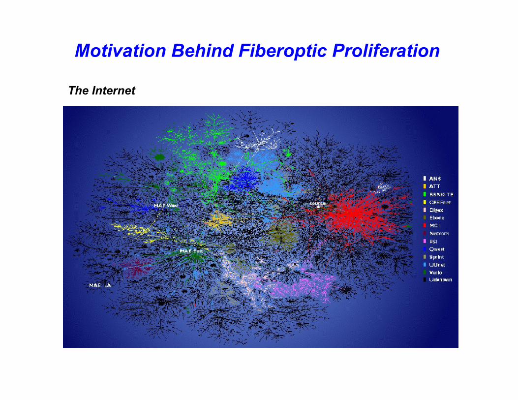
Motivation Behind Fiberoptic Proliferation
The Internet

Internet Traffic Growth
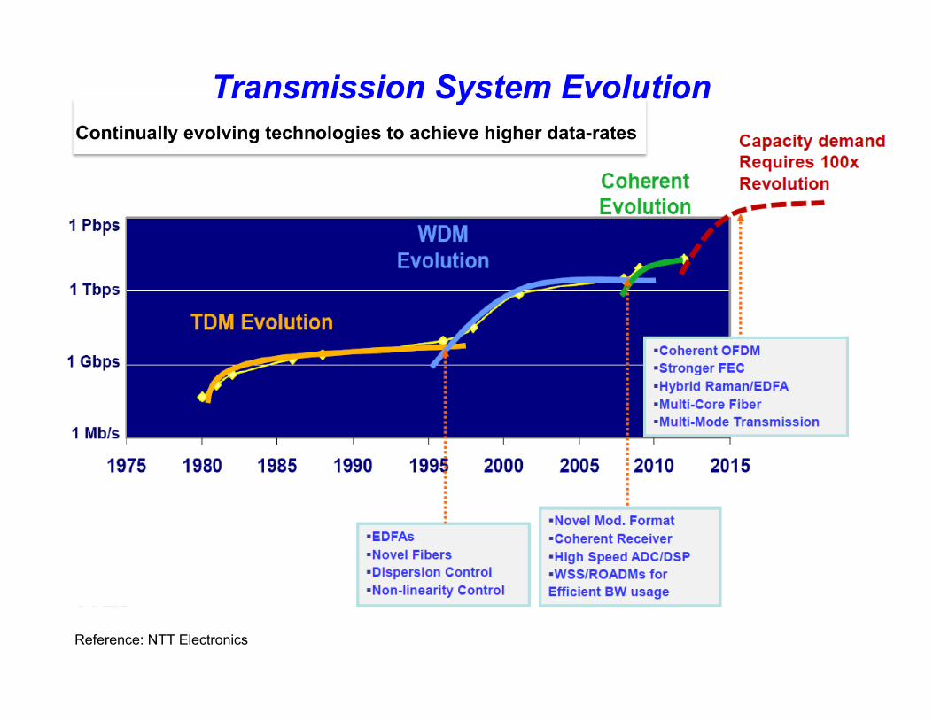
Reference: NTT Electronics
Transmission System Evolution Continually evolving technologies to achieve higher data-rates
• Introduction
• Laser Transmitters
• Seed Laser
• Optical Amplifiers
• Modulation
• Packaging

Semiconductor Lasers (also known as diode lasers or laser diodes)
• Typically a double heterodyne junction structure
• Laterally, the light is guided by total internal reflection
• Cavity is formed by cleaving the end facets, and placing dielectric coating on the backside

Characteristic LED Multi-Mode Diode Laser
Single-Mode Diode laser
Spectral width (nm)
20 -100
~5
<0.2
Rise-time
2 - 250
0.1 - 1
0.05 - 1
Modulation Bandwidth (GHz)
<0.3
20
>20
Fiber coupling efficiency
Very low
Moderate
High
Temperature sensitivity
Low
High
High
Communication distance
Moderate
Long
Longest
Communications data-rate
Moderate
High
Very High
Lifetime (hours)
1E5 to 1E11
1E6
1E6
Cost
Low
High
Highest
Comparison of Light Sources

Laser Wavelength Driven by Optical Attenuation in Fiber
• Loss due to absorption by impurities
– 1400nm peak due to OH ions
• Specified in loss per kilometer (dB/km)
– 0.40 dB/km at 1310nm – 0.25 dB/km at 1550nm
• Optical amplifiers available in
1550nm window
1310 Window
1550 Window

DFB Master (seed) Laser
Data-Driver Pump Lasers
Power Amplifier Electro-Optic Modulator
Master Oscillator Power-Amplifier (MOPA)

• Introduction
• Laser Transmitters
• Seed Laser
• Optical Amplifiers
• Modulation
• Packaging

Comparison of Single Mode Lasers
Multi-Mode Single-Mode Distributed FeedBack (DFB)

Diode Laser Temperature and Current Dependence
Temperature dependence ~0.3nm shift/°C
Spectrum variation based on current variations

• Relative Intensity Noise (RIN) • Output power fluctuations
• Back-reflection Noise • Noise generated from perturbation of lasing modes
• Modal Noise (Speckle) • Noise due to energy distribution variation. Occurs in multi-mode fiber
• Mode-Partition Noise • Due to fluctuations in the longitudinal modes of the laser
Diode Laser Intensity Noise

Reference: NTT website
Tunable Laser Transmitters
Tunable transmitter modules now commercially available • Example: tuned via fiber Bragg grating
• Introduction
• Laser Transmitters
• Seed Laser
• Optical Amplifiers
• Modulation
• Packaging

Optical Amplifiers
An optical amplifier is a device which amplifies the optical signal directly without ever converting it to electricity.
Reasons to use the optical amplifiers:
v Reliability
v Flexibility
v Duplication is perfect; photons are cloned
v Delivery of 100’s of Gb/s data-arte at 10’s of Watt power
Variety of optical amplifier types exists, including:

Optical Amplifier Types
Ø EDFA (Erbium-doped fiber amplifier) DOMINANT type uses doped fiber Ø Most commonly used in C-band (1530 - 1565 nm) Ø Also available in L-band and S-Band
Ø Raman Amplifier adds performance or more wavelength range, can use any type of fiber, any wavelength possible, now of interest for C, L, and S-band
Ø SOA (Semiconductor Optical Amplifier) also entering market, similar to EDFA but Er is in a planar waveguide, compact, C and L band
Ø EDWA (Erbium-Doped Waveguide Amplifier) also entering market, similar to EDFA but Er is in a planar waveguide, compact, C and L band
Ø TDFA, PDFA… doped fiber amplifiers like EDFA using other dopants to allow gain at other wavelength, i.e., Thulium TDFA for S-band

Fiber Amplifier Schematic (example)
Input
1480 or 980 nm Pump Laser
Erbium Doped Fiber
Output
Isolator Coupler

Pump Source
WDM Erbium Doped
fiber
Isolator Isolator
= Fusion Splice
Input Output
980 nm signal
1550 nm data signal
Pow
er le
vel
980 nm signal
1550 nm data signal
Pow
er le
vel Power
interchange between
pump and data
signals
Operation of an EDFA
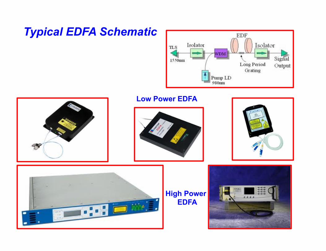
High Power EDFA
Low Power EDFA
Typical EDFA Schematic

Semiconductor Optical Amplifier (SOA)
• SOA is essentially a laser diode without a cavity (feedback) • SOAs optically amplify an input signal • SOAs are much more compact than EDFAs, but cannot deliver
as much output power
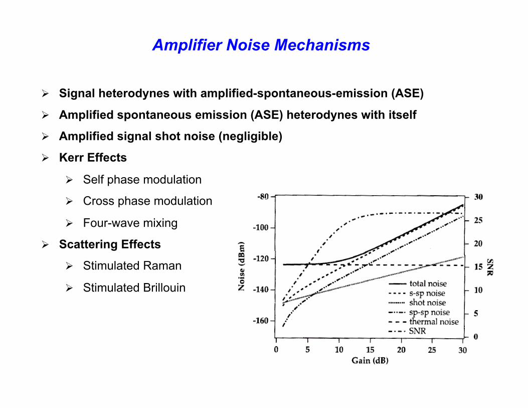
Amplifier Noise Mechanisms
Ø Signal heterodynes with amplified-spontaneous-emission (ASE)
Ø Amplified spontaneous emission (ASE) heterodynes with itself
Ø Amplified signal shot noise (negligible)
Ø Kerr Effects
Ø Self phase modulation
Ø Cross phase modulation
Ø Four-wave mixing
Ø Scattering Effects
Ø Stimulated Raman
Ø Stimulated Brillouin
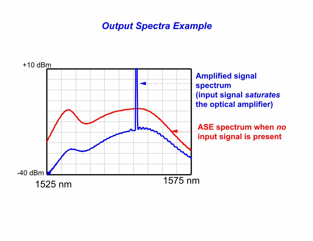
Output Spectra Example
ASE spectrum when no input signal is present
Amplified signal spectrum (input signal saturates the optical amplifier)
1575 nm -40 dBm
1525 nm
+10 dBm
• Introduction
• Laser Transmitters
• Seed Laser
• Optical Amplifiers
• Modulation
• Packaging

Multiplexing & Modulation Ø Wavelength Division Multiplexing (WDM) Ø Polarization Multiplexing (PM) Ø Frequency Shift Keying (FSK) Ø Phase Shift Keying (PSK) Ø Quadrature Amplitude Modulation (QAM) Ø Space (not implemented yet)
Reference: Alcatel / Lucent


Indirect Modulators
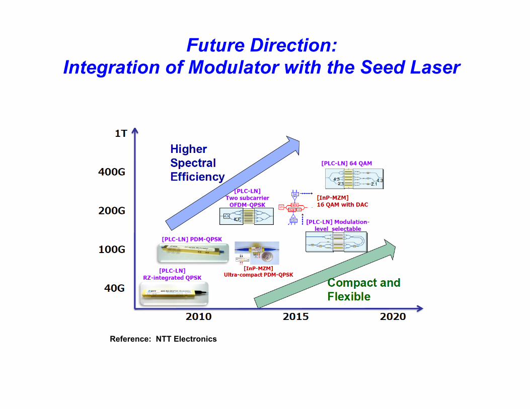
Future Direction: Integration of Modulator with the Seed Laser
Reference: NTT Electronics

Laser Transmitter Characterization
PARAMETER MEASURING INSTRUMENT ACCURACY Power Power meter pW, nW, uW Wavelength Optical spectrum analyzer
Interfermetric-based ±15pm ±5 pm
Linewidth, chirp, modulation effects
High resolution spectrometer ±15 pm
Relative intensity noise, ASE noise…
Signal analyzer (optical)
Modulation bandwidth (EO response)
Component analyzer (optical)
Reference: Agilent Technologies

Measurement of Communications Quality
• An open Eye Diagram is indicative of low BER (bit error rate) • Eye-diagram is super-imposition of bit sequences
Reference: Agilent Technologies

• Introduction
• Laser Transmitters
• Seed Laser
• Optical Amplifiers
• Modulation
• Packaging

Fiber input/output
(Nd, Yb, Er… ion) doped fiber loop
Pump laser Fiber coupler
Fiber Amplifier’s Interior

Pluggable Modulatable Seed Lasers
For 10Gbit Ethernet and other Fiberoptic Transmission/reception Applications
Reference: Finisar
TAKE AWAY v Only certain semiconductor lasers, and the fiber amplifiers are the
practical lasers for fiberoptic communications.
v Master-Oscillator, Power-Amplifier (MOPA) is a common approach for providing a modulated transmitter
v Current push is for cost-effective 100 Gb/s coherent laser transmitters.
v Fiber amplifiers provide high power levels, wide spectral bandwidth, extremely high modulation rate, and the reliability needed for most demanding fiberoptic comm applications.
v External modulation provides cleaner, higher extinction ratio pulses relative to direct modulation
v Design of high power amplifiers should avoid noise and nonlinear effects
v Future direction points towards miniaturization and integration

QUESTIONS


