Last Updated 11/17/2015 SOUTH FLORIDA RAIL CORRIDOR DESIGN & CONSTRUCTION STANDARDS - PIPELINES Scope A. These Standards shall apply to the design and construction of pipelines carrying flammable or non-flammable substances and casings containing wires, cables, and carrier pipes under, across and upon property owned by the Florida Department of Transportation (FDOT) for the South Florida Rail Corridor (SFRC). B. It is to be clearly understood that FDOT owns its SFRC right-of-way for the primary purpose of operating a railroad. All occupancies shall therefore be designed and constructed so that rail operations and facilities are not interfered with, interrupted, or endangered. In addition, the proposed facility shall be located to minimize encumbrance to the right-of-way so that the railroad will have unrestricted use of its property for current and future operations. Definitions Carrier Pipe Pipe used to transport the product Casing Pipe Pipe through which the carrier pipe is installed under main tracks Owner (Applicant) Individual, Corporation, Municipality, or other public or private entity desiring occupancy of SFRC property Siding or Industry Tracks Tracks located off the SFRC right-of-way serving an industry SFRC South Florida Rail Corridor SFRTA South Florida Regional Transportation Authority SFRC Design and Construction Standards – Pipelines Page 1
Transcript
Last Updated 11/17/2015
SOUTH FLORIDA RAIL CORRIDOR DESIGN & CONSTRUCTION
STANDARDS - PIPELINES Scope
A. These Standards shall apply to the design and construction of pipelines carrying flammable or non-flammable substances and casings containing wires, cables, and carrier pipes under, across and upon property owned by the Florida Department of Transportation (FDOT) for the South Florida Rail Corridor (SFRC).
B. It is to be clearly understood that FDOT owns its SFRC right-of-way for the primary purpose of operating a railroad. All occupancies shall therefore be designed and constructed so that rail operations and facilities are not interfered with, interrupted, or endangered. In addition, the proposed facility shall be located to minimize encumbrance to the right-of-way so that the railroad will have unrestricted use of its property for current and future operations.
Definitions
Carrier Pipe Pipe used to transport the product
Casing Pipe Pipe through which the carrier pipe is installed under main tracks
Owner (Applicant) Individual, Corporation, Municipality, or other public or private entity desiring occupancy of SFRC property
Siding or Industry Tracks Tracks located off the SFRC right-of-way serving an industry
SFRC South Florida Rail Corridor
SFRTA South Florida Regional Transportation Authority
SFRC Design and Construction Standards – Pipelines Page 1
Application for Occupancy
A. Owner (Applicant) desiring occupancy of SFRC property by pipeline occupation must agree to approval by SFRTA of all engineering and construction details and execution of an appropriate FDOT Utility Permit.
B. The SFRTA Application for Facility/Utility Installations may be secured from the SFRTA website at www.sfrta.fl.gov .
C. All requirements for securing FDOT Utility Permits and FDOT General Use Permits for construction are outlined on the SFRTA website.
Site Inspections
A. For longitudinal occupancy of SFRC right-of-way, a site inspection along the proposed pipeline route may be required before final design plans are prepared. When a site inspection is required, the Applicant and/or the engineer must meet with an SFRTA representative to view the entire length of the proposed occupancy; the Applicant will be informed of the need for a meeting during the application process.
B. Prior to the site inspection the Applicant must submit the following information:
i. A plan view of the proposed route showing all tracks, both SFRC right-of-way lines, and all other facilities located on the right-of-way. The distance from the proposed pipeline to the adjacent track and to the right-of-way lines must be shown.
ii. A complete application form. iii. Typical cross sections along the proposed route.
C. Site inspections for pipe crossings are not required unless, in the opinion of SFRTA, the
size and location of the facility warrant an inspection.
General Requirements
A. Use of Casing Pipe
i. A casing pipe will be required for all pipeline crossings carrying liquid or gaseous substances.
ii. For non-pressure sewer or drainage crossings, where the installation can be made by open cut (see Construction Requirements Section) or reinforced concrete pipe
SFRC Design and Construction Standards – Pipelines Page 2
can be jacked under the railroad (see Construction Requirements Section), the casing pipe may be omitted.
iii. Pressure pipelines that are located within 25 feet of the centerline of any track shall be encased.
iv. At proposed pipe crossings, the casing pipe shall be laid across the entire width of the right-of-way, except where a greater length is required to comply with the Design Requirements - Casing Pipe Section of this standard, even though such extension is beyond the right-of-way.
v. At the discretion of SFRTA, a casing pipe may be required for any application regardless of the commodity carried.
B. Location of Pipeline on the SFRC Right-of-Way
i. Pipelines laid longitudinally on the SFRC right-of-way shall be located as far as practicable from any tracks or other important structures and as close to the SFRC right-of-way line as possible. Longitudinal pipelines must not be located in earth embankments or within ditches located in the right-of-way.
ii. Pipelines shall be located, where practicable, to cross tracks at approximate right angles to the track, but preferably at not less than 45 degrees.
iii. Pipelines shall not be placed within a culvert, under railroad bridges, nor closer than 45 feet to any portion of any railroad bridge, building, or other important structure, except in special cases, and then by special design, as approved by SFRTA.
iv. Pipelines shall not be located within the limits of a turnout (switch) when crossing the track. The limits of the turnout extend from the point of the switch to 15 feet beyond the last long timber.
v. Pipeline installations shall not be designed as an open cut installation where the pipeline is to be located within the limits of a grade crossing. If it is shown that no other method of installation is possible, the owner shall be responsible for all costs associated with the removal and reconstruction of the grade crossing.
vi. Pipelines carrying liquefied petroleum gas shall, where practicable, cross the railroad where tracks are located on embankment.
C. Depth of Installation
i. Pipelines conveying non flammable substances
a) Casing/carrier pipes placed under SFRC tracks shall be not less than 5 feet 6 inches from the base of the rail to the top of the pipe at its shallowest point.
b) Pipelines laid longitudinally on SFRC’s right-of-way 50 feet or less from the centerline of the track shall be buried not less than four (4) feet from ground
SFRC Design and Construction Standards – Pipelines Page 3
surface to top of pipe. Where the pipeline is laid more than 50 feet from centerline of track, the minimum cover shall be at least three (3) feet.
ii. Pipelines conveying flammable substance
a) Casing/carrier pipes placed under SFRC tracks shall be not less than 5 feet 6 inches from the base of rail to the top of the pipe at its shallowest point. On other portions of the right-of-way where the pipe is not directly beneath any track the depth from ground surface or from bottom of ditch to top of pipe shall not be less than three (3) feet. Where three (3) feet of cover cannot be provided from bottom of ditch, a 6-inch thick reinforced concrete slab shall be provided over the pipeline for protection.
b) Pipelines laid longitudinally on the SFRC’s right-of-way 50 feet or less from the centerline of the track shall be buried not less than less than six (6) feet from the ground surface to the top of the pipe. Where the pipeline is laid more than 50 feet from centerline of track the minimum cover shall be at least five (5) feet.
D. Pipelines within Limits of a Public Roadway
i. Pipelines within the limits of a public roadway are subject to all the requirements of this standard and must be designed and installed in accordance with this standard.
ii. The limits of the roadway right-of-way must be clearly shown on the plans.
E. Modification of Existing Facilities
i. Any replacement or modification of an existing carrier pipe and/or casing shall be considered as a new installation, subject to the requirements of this standard.
F. Abandoned Facilities
i. The owner of all pipe crossings proposed for abandonment shall notify SFRTA, in writing, of the intention to abandon.
ii. Abandoned pipelines shall be removed or completely filled with cement grout, compacted sand, or other methods as approved by SFRTA.
iii. Abandoned manholes and other structures shall be removed to a minimum depth of 2 feet below finished grade and completely filled with cement grout, compacted sand or other methods as approved by SFRTA.
SFRC Design and Construction Standards – Pipelines Page 4
G. Insulation
i. Pipelines and casing should be suitably insulated from underground conduits carrying electric wires on SFRC right-of-way.
H. Corrosion Protection and Petroleum Leak Prevention
i. Pipelines on SFRC right-of-way that carry petroleum products or hazardous liquids shall be designed in accordance with current federal, state, and local regulations that mandate leak detection automatic shutoff, leak monitoring, sacrificial anodes, and/or exterior coatings to minimize corrosion and prevent petroleum releases.
I. Plastic Carrier Pipe Materials
i. Plastic carrier pipe materials include, but are not limited to, thermoplastic and thermoset plastic pipes. Thermoplastic types include Polyvinyl Chloride (PVC), Acrylonitrile Butadiene Styrene (ABS), High Density Polyethylene (HDPE), Polyethylene (PE), Polybutylene (PB), Cellulose Acetate Butyrate (CAB), and Styrene Rubber (SR). Thermoset types include Reinforced Plastic Mortar (RPM), Reinforced Thermosetting Resin (RTR), and Fiberglass Reinforce Plastic (FRP).
ii. Plastic carrier pipelines shall be encased according to AREMA Chapter 1, Section 5.1.5.
iii. Plastic pipe material shall not be used to convey liquid flammable substances. iv. Plastic pipe material shall be resistant to the chemicals with which contact can be
anticipated. Plastic carrier pipe shall not be used where there is potential for contact with petroleum contaminated soils or other non-polar organic compounds that may be present in surrounding soils.
v. Plastic carrier pipe can be utilized to convey flammable gas products provided the pipe material is compatible with the type of product conveyed and the maximum allowable operating pressure is less than 100 psi. Carrier pipe materials, design and installation shall conform to 49CFR 178 to 199 and the American National Standards Institute ASME B31.8 and ASTM D2513. Codes, specifications, and regulations current at the time of construction of the pipeline shall govern the installation of the facility within the SFRC right-of-way. The proof testing of the strength of carrier pipe shall be in accordance with ANSI requirements.
vi. Plastic carrier pipe conveying flammable substances shall be encased the entire limits of the right-of-way. If special conditions exist which prevent encasement within the entire limits of the right-of-way, SFRTA must approve the minimum encased length.
vii. Plastic carrier pipe must be encased under all tracks, including sidings and industrial tracks within the limits of the SFRC right-of-way.
SFRC Design and Construction Standards – Pipelines Page 5
viii. Longitudinal carrier pipeline shall be steel or ductile iron. Plastic carrier pipe may be utilized for longitudinal installation with approval by SFRTA, but shall be fully encased within the limits of the right-of-way.
ix. Codes, specifications, and regulations current at the time of construction of the pipeline shall govern the installation of the facility within the SFRC right-of-way. The proof testing of the strength of carrier pipe shall be in accordance with ANSI requirements. Standards Number Carrier Pipe Properties
ANSI/AWWA C900 PVC pressure pipe 4” through 12”
ANSI/AWWA C901 PE pressure pipe and tubing ½” through 3” for water
ANSI/AWWA C902 PE pressure pipe and tubing ½” through 3” for water
ANSI/AWWA C905 PVC water pipe, 14” through 36”
ANSI/AWWA C906 PE pressure pipe and fittings 4”- 63” for water
ANSI/AWWA C907 PVC pressure fittings and fittings 4”-8”
ANSI/AWWA C950 Fiberglass pressure pipe
Soil Investigation
A. General
i. Test borings or other soil investigations, approved by SFRTA, shall be made to determine the nature of the underlying material for all pipe crossings with casing pipe sizes greater than or equal to 48 inches in diameter and larger under tracks.
ii. Test borings or other soil investigations, approved by SFRTA, may be required when, in the judgment of SFRTA, they are necessary to determine the adequacy of the design and construction of pipe crossings with casings less than 48 inches in diameter and for other facilities located on the SFRC right-of-way. The applicant shall be responsible for the location and notification of all underground utilities, including SFRC signal cables.
B. Location
i. Borings shall be made on each side of the track), on the centerline of the pipe crossing, and as close to the tracks as practicable.
SFRC Design and Construction Standards – Pipelines Page 6
ii. Test boring logs shall be accompanied with a plan, drawn to scale, showing the location of the borings in relation to the tracks and the proposed pipe.
C. Sampling
i. Test borings shall be made in accordance with current ASTM Designation D1586 except that sampling must be continuous from the ground surface to five (5) feet below the proposed invert unless rock is encountered before this depth. Where rock is encountered, it is to be cored using a series “M” Double Tube Core Barrel, with a diamond bit, capable of retrieving a rock core at least 1 5/8” in diameter. Individual core runs are not to exceed five (5) feet in length.
ii. All borings shall be sealed, for their full depth, with a 4-3-1 bentonite-cement-sand grout after accurate ground water readings have been taken and recorded.
iii. Soil samples taken from auger vanes or return washwater are not acceptable.
D. Boring Logs
i. Test boring logs shall clearly indicate all of the following:
a) Boring number as shown on the required boring location plan.
b) Ground elevation at each boring using same datum as the pipeline construction plans.
c) Engineering description of soils or rock encountered.
d) Depth and percent recovery of all soil samples.
e) Depth from surface for each change in strata.
f) Blows for each six (6) inches of penetration for the standard penetration test described in ASTM D1586. Blows for lesser penetrations should be recorded.
g) Percent recovery and Rock Quality Designation (RQD) for all rock cores.
h) Depth to ground water while sampling and when it has stabilized in the bore hole.
ii. The location of the carrier pipe and/or casing pipe shall be superimposed on the boring logs before submission to SFRTA.
E. Additional Information
i. When directed by SFRTA, additional borings may be required for the purpose of taking undisturbed thin-wall piston samples or Dennison type samples for
SFRC Design and Construction Standards – Pipelines Page 7
laboratory testing to determine the index and engineering properties of certain soil strata.
Design Requirements
A. Design Loads
i. General Requirements
a) All pipes, manholes, and other facilities shall be designed for the external and internal loads to which they will be subjected.
b) To allow for placement of additional track(s) or shifting of existing track(s), all proposed pipelines or structures shall be designed as if a railroad loading is directly above the facility.
ii. Earth Load
a) The dead load of the earth shall be considered as 120 pounds per cubic foot unless soil conditions warrant the use of a higher value.
iii. Railroad Load (live load and impact)
a) The railroad live load used shall be a Cooper E-80 loading. This loading consists of 80 kip axle loads spaced 5 feet on centers (refer to current AREMA Manual for Railway Engineering).
b) An impact factor of 1.75 (multiply live load by the impact factor) shall be used for depth of cover up to five (5) feet. Between five (5) and 30 feet, the impact factor is reduced by 0.03 per foot of depth. Below a depth of 30 feet, the impact factor is one.
c) The values shown in Table 1 shall be used for the vertical pressure on a buried structure for the various heights of cover.
d) To determine the horizontal pressure caused by the railroad loading on a sheet pile wall or other structure adjacent to the track, the Boussinesq analysis shall be used. The load on the track shall be taken as a strip load with a width equal to the length of the ties which is typically, 8.5 feet. The vertical surcharge, q (psf), caused by each axle, shall be uniform and equal to the axle load divided by the tie length and the axle spacing, 5 feet. For the E-80 loading this results in:
Q = 80,000 / (8.5 X 5) = 1882 psf
The horizontal pressure due to the live load surcharge at any point on the wall or other structure is Ph and can be calculated by the following:
Ph = (2q/∏) (β-sin β(cos2∞))
SFRC Design and Construction Standards – Pipelines Page 8
Table 1
Live loads, including impact, for various heights of cover for a Cooper E-80 loading.
e) The vertical and horizontal pressures given above shall be used unless an alternate design method is approved by SFRTA. Proposals to use an alternate design method must include acceptable references and a statement explaining the justification for choosing the alternate method.
B. Design Assumptions
To design a casing pipe or uncased carrier pipe for the external loads on the SFRC right-of-way, the following design assumptions shall be used, unless site conditions indicate more conservative values are required as identified by SFRTA:
i. Flexible Pipe (Steel, DIP, CMP, Tunnel Liner Plate)
a) Steel Pipe (Bored and jacked in place) • Spangler’s Iowa formula shall be used for design with:
Deflection lag factor - Df = 1.5 Modulus of soil reaction - E’ = 1080 psi Bedding Constant - Kb = 0.096 Soil loading constant - Ku’ = 0.13 Allowable deflection of pipe - 3% of pipe diameter
SFRC Design and Construction Standards – Pipelines Page 9
b) Ductile Iron Pipe (Open Cut) • AWWA Specifications C150 shall be used for design with:
Pipe laying condition = Type 3 Earth load - ANSI A 51.50 prism method
c) Corrugated Steel Pipe & Corrugated Structural Steel Plate Pipe (Open Cut) • AREMA Chapter 1, Section 4.9 & 4.10 shall be used for design with:
Soil stiffness factor - K=0.33 Railroad impact as per Design Requirements - Casing Pipe Section of these Standards.
d) Tunnel Liner Plate (Tunneled) • AREMA Chapter 1, Part 4, Section 4.16 shall be used for design with:
Soil stiffness factor - K=0.33 Railroad impact as per Design Requirements-Casing Pipe Section of these Standards.
ii. Rigid Pipe (RCP, Vitrified Clay Pipe and PCCP)
a) Reinforced Concrete Pipe, Vitrified Clay pipe and Prestressed Concrete Cylinder Pipe (Open Cut) • American Concrete Pipe Association design manual shall be used for
design with: Marston load theory used for earth load Bedding (Load Factor) - Lf = 1.9 Factor of Safety - FS = 1.25 for RCP or FS = 1.50 for VCP Railroad impact as per Design Requirements - Casing Pipe Section of these Standards.
b) Reinforced Concrete pipe (Jacked)
• American Concrete Pipe Association design manual shall be used for design with:
Marston load theory used for earth load Bedding (Load Factor) - Lf = 3.0 Factor of Safety = 1.25 Railroad impact as per Design Requirements-Design Loads Section of these Standards. Others – As approved by SFRTA
SFRC Design and Construction Standards – Pipelines Page 10
C. Casing Pipe
i. General Requirements
a) Casing pipe shall be so constructed as to prevent leakage of any substance from the casing throughout its length, except at ends of casing where ends are left open, or through vent pipes when ends of casing are sealed. Casing shall be installed so as to prevent the formation of a waterway under the railroad, and with an even bearing throughout its length, and shall slope to one end (except for longitudinal occupancy).
b) The casing pipe and joints shall be of steel and of leak proof construction when the pipeline is carrying liquid flammable products or highly volatile substances under pressure.
c) The inside diameter of the casing pipe shall be such as to allow the carrier pipe to be removed subsequently without disturbing the casing or the roadbed. For steel pipe casings, the inside diameter of the casing pipe shall be at least two (2) inches greater than the largest outside diameter of the carrier pipe joints or couplings, for carrier pipe less than 6 inches in diameter; and at least 4 inches greater for carrier pipe six (6) inches and over in diameter.
d) For flexible casing pipe, a maximum vertical deflection of the casing pipe of 3% of its diameter, plus ½ inch clearance shall be provided so that no loads from the roadbed, track, traffic, or casing pipe itself are transmitted to the carrier pipe. When insulators are used on the carrier pipe, the inside diameter of the flexible casing pipe shall be at least two (2) inches greater than the outside diameter of the carrier pipe for pipe less than eight (8) inches in diameter; at least 3 ¼ inches greater for pipe eight (8) inches to 16 inches, inclusive, in diameter and at least 4 ½ inches greater for pipe 18 inches and over in diameter.
e) In no event shall the casing pipe diameter be larger than is necessary to permit the insertion of the carrier pipe.
f) Casing pipe under railroad tracks and across SFRC’s right-of-way shall extend the greater of the following distances, measured at right angle to centerline of track:
• Across the entire width of the SFRC right-of-way • Three (3) feet beyond the ditch line • Two (2) feet beyond the toe slope • A minimum distance of 25 feet from each side of centerline of outside
track when casing is open at both ends • Beyond the theoretical railroad embankment influence line. This line
begins at a point 12 feet horizontally from centerline of track, 18 inches below top-of-rail, and extends downward on a 1 ½ (H) to 1 (V) slope.
g) If additional tracks are constructed in the future, the casing shall be extended correspondingly at the Owner’s expense.
SFRC Design and Construction Standards – Pipelines Page 11
ii. Steel Pipe
a) Steel pipe may be installed by open cut, boring or jacking based on
situation. b) Steel pipe shall have a specified minimum yield strength, SMYS, of at least
35,000 psi. The ASTM or API Standards and grade for the pipe are to be shown on the Application Form.
c) Joints between the sections of pipe shall be fully welded around the complete circumference of the pipe.
d) Steel casing pipe, with a minimum cover of 5.5 feet, shall have a minimum wall thickness as shown in Table 2, unless computations indicate that a thicker wall is required.
SFRC Design and Construction Standards – Pipelines Page 12
e) Coated steel pipe that is bored or jacked into place shall conform to the wall thickness requirements for uncoated steel pipe since the coating may be damaged during installation.
f) Smooth wall steel pipes with a nominal diameter over 72 inches will not be permitted.
iii. Ductile Iron Pipe
a) Ductile iron pipe may be used only at the sole discretion of SFRTA when placed by the open cut method. Jacking or boring through the railroad embankment is not permitted due to the bell and spigot joints.
b) Ductile iron pipe shall conform to the requirements of ANSI A21.51/AWWA C-151. Class 56 pipes shall be used unless computations, in accordance with the Design Requirements-Design Loads and Design Assumptions sections, are provided.
c) Table 3 is based on the design assumptions given in the Design Requirements-Design Loads section with minimum cover of 5feet 6 inches. This table is provided for information only.
d) The pipe shall have mechanical or push on type joints. SFRC Design and Construction Standards – Pipelines Page 13
iv. Corrugated Steel Pipe and Corrugated Structural Steel Plate Pipe
a) Corrugated steel pipe and corrugated structural steel plate pipe may be used for a casing only when placed by the open cut method. Jacking or boring through the railroad embankment is not permitted.
b) Corrugated steel pipe and corrugated structural steel plate pipe may be used for a casing provided the pressure in the carrier pipe is less than 100 psi.
c) Pipe shall be bituminous coated and shall conform to the current AREMA Manual Chapter 1, Part 4.
d) Corrugated steel pipe shall have a minimum sheet thickness as shown in Table 4. Corrugated structural steel plate pipe shall have a minimum plate thickness of 8 gage, 0.168 in. If computations indicate that a greater thickness is required, the thicker sheet or plate shall be used.
Table 4
Pipe Diameter Sheet Thickness (Inches) (Gage) (Inches) 12 to 30 14 0.079 36 12 0.109 42 to 54 10 0.138 60 to 120 8 0.168
v. Steel Tunnel Liner Plate
a) Liner plates shall be installed by the tunneling method as detailed in the Construction Requirements-Method of Installation section of these Standards.
b) Tunnel liner plates shall be galvanized and bituminous coated and shall conform to the current AREMA Manual. If the tunnel liner plates are used only to maintain a tunneled opening until the carrier pipe is installed, and the annular space between the carrier pipe is installed, and the annular space between the carrier pipe and the tunnel liner is completely filled with cement grout within a reasonably short time after completion of the tunnel, then the tunnel liner plates need not be galvanized and coated.
SFRC Design and Construction Standards – Pipelines Page 14
c) Tunnel liner plates are to be a minimum of 12 gage and shall be fabricated from structural quality, hot-rolled, carbon-steel sheets or plates conforming to ASTM Specifications A 1011.
d) The following liner plate information must be shown in the Application for Facility/Utility Installations supporting information:
• Number of flanges (2 or 4) • Width of plate • Type of plate (smooth or corrugated)
vi. Reinforced Concrete Pipe
a) Reinforced concrete pipes shall be installed by the open cut (at the sole discretion of SFRTA) or jacking method.
b) Reinforced concrete pipe shall conform to ASTM Specifications C 76. Class V pipe, Wall B or C shall be used unless computations, in accordance with the Design Requirements-Design Assumptions, are provided.
c) Reinforced concrete pipe may be used for casing provided the pressure in the carrier pipe is less than 100 psi.
d) Pipe placed by open cut shall be installed in accordance with the AREMA Manual for Railway Engineering except that backfill and compaction shall be in accordance with the Construction Requirements-Method of Installation section of these Standards.
e) Pipe jacked into place shall have tongue and groove joints and shall be installed in accordance with the Construction-Requirements Method of Installation section of these Standards.
f) Joints between sections of the RCP shall be sealed with a gasket conforming to ASTM C 443 or approval equal.
vii. Concrete Encasement
a) At locations where the installation is by open cut and a casing pipe is required, but cannot be installed due to elbows or other obstructions, concrete encasement may be used when approved by SFRTA.
b) The concrete encasement must provide a minimum cover of 6 inches of concrete around the pipe. A 6X6 - W2.9 X W2.9 welded wire fabric shall be placed in the concrete on all sides.
D. Carrier Pipe
i. General Requirements
a) The pipe shall be laid with sufficient slack so that it is not in tension.
SFRC Design and Construction Standards – Pipelines Page 15
b) Steel pipe shall not be used to convey sewage, storm water, or other liquids that could cause corrosion.
c) Carrier pipes located on SFRC’s right-of-way shall be manufactured in accordance with the following specifications: • Steel Pipe – The ASTM or API Standards and grade for the pipe is to
be shown on the Application Form. The specified minimum yield strength is to be at least 35,000 psi. For flammable substances, see the Design Requirements-Carrier Pipe Section of this document for additional requirements.
• Ductile Iron Pipe – ANSI A21.51/AWWA C151 • Corrugated Metal Pipe – AREMA Chapter 1, Part 4 • Reinforced Concrete Pipe – ASTM C 76 • Vitrified Clay Pipe – ASTM C 700 • Prestressed Concrete Cylinder Pipe – AWWA C301 • Reinforced Concrete Cylinder Pipe- AWWA C300 • Others-As approved by SFRTA
d) Carrier pipe installed within a casing pipe shall be designed for the internal pressure to which it will be subjected.
e) Gravity flow carrier pipes, installed without casing pipe, shall meet the requirements of the particular pipe material, as given in the Design-Requirements-Casing Pipe Section of these Standards.
f) Design computations, stamped by a Professional Engineer, must be submitted for all uncased pressure pipelines installed on SFRC’s right-of-way. The pipe must be designed for the internal and external loads (See the Design-Requirement Section of this document) to which it may be subjected. The design assumptions given in the Design Requirements Section shall apply.
ii. Pipelines Carrying Flammable Substances
a) Pipelines carrying oil, liquefied petroleum gas and other flammable products shall be of steel and conform to the requirements of the current ASME B 31.4 Liquid Transportation Systems for Hydrocarbons, Liquid Petroleum Gas, Anhydrous Ammonia, and Alcohols, and other applicable ASME codes, except that the maximum allowable stresses for design of steel pipe shall not exceed the following percentages of the specified minimum yield strength (multiplied by the longitudinal joint factor) of the pipe as defined in the above codes:
SFRC Design and Construction Standards – Pipelines Page 16
• The following percentages apply to hoop stress in steel pipe within a casing under railroad tracks, across railroad right-of-way and longitudinally on railroad right-of-way: o Seventy two percent on oil pipelines. o Fifty percent for pipelines carrying condensate, natural gasoline,
natural gas liquids, liquefied petroleum gas, and other liquid petroleum products.
o Sixty percent for installation on gas pipelines. • The following percentages apply to hoop stress in steel pipe laid
longitudinally on railroad right-of-way without casing: o Sixty percent for oil pipelines. o Forty percent for pipelines carrying condensate, natural gasoline,
natural gas liquids, liquefied petroleum gas and other liquid petroleum products.
b) Computations, based on the above requirements and stamped by a Professional Engineer shall be submitted with the application for occupancy.
iii. Uncased Pipelines Carrying Gas
a) Pipelines carrying flammable and nonflammable gas products shall be steel (Nonflammable – plastic) and shall conform to the requirements of the current ASME B 31.8 Gas Transmission and Distribution Piping Systems, and other applicable ANSI codes.
b) The minimum wall thickness for uncased carrier pipe shall be in accordance with the values provided in AREMA Chapter 1, Part 5.
c) A durable coating, which will resist abrasion (fusion bonded epoxy or other suitable material), shall be used to protect the uncased pipeline when the boring method of installation is used.
d) If SFRTA determines there is the potential for damage to the uncased pipeline (foreign material in the sub grade, third party damage, etc.), special protection of the pipeline will be required. Special protection may include the use of concrete jacketed carrier pipe, a protection slab over the pipeline, increased depth of bury, or other means.
F. Casing Pipe End Seals
i. Casings for carrier pipes of flammable and hazardous substances shall be suitably sealed to the outside of the carrier pipe. Details of the end seals shall be shown on the plans.
SFRC Design and Construction Standards – Pipelines Page 17
ii. Casings for carrier pipes of non-flammable substances shall have both ends of the casing blocked up in such a way as to prevent the entrance of foreign material, but allowing leakage to pass in the event of a carrier break.
iii. The ends of a casing pipe may be left open when the ends are at or above ground surface and above high water level, provided drainage is afforded in such a manner that leakage will be conducted away from railroad tracks and structures.
F. Vents
i. Sealed casings for flammable substances shall be properly vented. Vent pipes shall be of sufficient diameter, but in no case less than two (2) inches in diameter, and shall be attached near each end of the casing and project through the ground surface at right-of-way lines or not less than 45 feet, measured at right angles from centerline of nearest track.
ii. Vent pipes shall extend not less than four (4) feet above the ground surface. Top of vent pipe shall have a down-turned elbow, properly screened, or a relief valve. Vents in locations subject to high water shall be extended above the maximum elevation of high water and shall be supported and protected in a manner approved by SFRTA.
iii. Vent pipes shall be at least four (4) feet, vertically, from aerial electric wires or greater if requires by National Electrical Safety Code (ANSI C2).
iv. When the pipeline is in a public highway, street type vents shall be installed.
G. Signs
i. All pipelines (except those in streets where it would not be practical to do so) shall be prominently marked at right-of-way lines (on both sides of track for crossings) by durable, weather proof signs located over the centerline of the pipe. Signs shall show the following:
Name and address of the owner Contents of pipe Pressure of pipe Pipe depth below grade point of a sign Emergency telephone number in event of pipe rupture
ii. For pipelines running longitudinally on the SFRC right-of-way, signs shall be
placed over the pipe (or offset and appropriately marked) at all changes in direction of the pipeline. Such signs should also be located so that when standing at one sign the next adjacent marker in either direction is visible. In no event shall they be placed more than 500 feet apart unless otherwise specified by SFRTA.
iii. The Owner must maintain all signs on the SFRC right-of-way as long as the occupational agreement is in effect.
SFRC Design and Construction Standards – Pipelines Page 18
H. Warning Tape
i. All pressure Pipelines installed by the trench method, without a casing, shall have a warning tape placed directly above the pipeline, two (2) feet below the ground surface.
I. Shut-off Valves
i. Accessible emergency shut-off valves shall be installed within 2,000 feet on both sides of the pipeline crossing or longitudinal occupancy.
ii. Location of valves shall be in compliance with United States Department of Transportation, minimum Federal Safety Standards as set forth in 49 CFR 192, or at the discretion of SFRTA.
J. Cathodic Protection
i. Cathodic protection shall be applied to all pipelines carrying flammable substances on the SFRC right-of-way.
ii. For crossings and other locations where the pipeline must be placed within a casing, the casing is to have cathodic protection or the wall thickness is to be increased to the requirements of Table 2 of these Standards.
iii. Uncased gas carrier pipes must be coated and cathodically protected to industry standards and test sites, for monitoring the pipeline, provided within 50 feet of the crossing.
iv. Where casing and/or carrier pipes are cathodically protected by other than anodes, SFRTA shall be notified and a suitable test made to ensure that other railroad structures and facilities are adequately protected from the cathodic current in accordance with the recommendation of current Reports of Correlating Committee on Cathodic Protection, published by the National Association of Corrosion Engineers.
v. Where sacrificial anodes are used, the locations shall be marked with durable signs.
K. Manholes
i. Manholes shall not be located on SFRC right-of-way where possible. At locations where this is not practical, including longitudinally occupancies, manholes shall be precast concrete sections conforming to ASTM Designation C 478, “Specifications for Precast Concrete Manhole Sections”.
ii. The top of manholes located on SFRC right-of-way shall be flush with top of ground.
SFRC Design and Construction Standards – Pipelines Page 19
iii. The distance from centerline of adjacent track to centerline of proposed manhole shall be shown on the plans.
L. Box Culverts
i. Reinforced concrete box culverts shall be designed in conformance with SFRTA Standards and current AREMA Manual for a Cooper E 80 loading.
M. Drainage
i. Occupancies shall be designed, and their construction shall be accomplished, so that adequate and uninterrupted drainage of the SFRC right-of-way is maintained.
ii. All pipes, ditches and other structures carrying surface drainage on the SFRC right-of-way and/or under SFRC tracks shall be designed to meet the requirements of the South Florida Water Management District. Plans submitted to SFRTA for approval shall be prepared by a Professional Engineer registered in the State of Florida and shall indicate design, suitable topographic plans, and outline of the total drainage area.
iii. If the drainage is to discharge into an existing drainage channel on SFRC right-of-way and/or through a drainage structure under SFRC’s track(s), the computations must include the hydraulic analysis of any existing ditch and/or structure.
iv. When calculating the capacity of existing or proposed drainage structures, under SFRC’s tracks, the headwater calculation at the structure shall not be greater than one (1).
v. Pipes used to carry surface drainage on SFRC right-of-way shall have a minimum diameter of 24 inches.
vi. Detention ponds must not be placed on any part of SFRC right-of-way. Also, the railroad embankment must not be used as any part of a detention pond structure.
vii. Formal approval of the proposed design, by the appropriate government agency having jurisdiction, shall be submitted with the drainage computations.
N. Pipelines on Bridges
i. Pipelines cannot be installed on any bridge carrying SFRC tracks.
ii. Overhead pipe bridges will only be considered over SFRC right-of-way when underground installation of the pipeline is not possible. The Applicant must show that no practicable alternative is available and overhead pipe bridges will be permitted provided the following conditions are met:
a) The vertical clearance, distance from top of rail to closest component of structure, is shown and is a minimum of 23 feet, measured at a point 9 feet horizontally from centerline track.
SFRC Design and Construction Standards – Pipelines Page 20
b) The support bents for the overhead structure are located off SFRC right-of-way or minimum clear distance of 20 feet from centerline track, whichever distance is greater.
c) Support bents within 25 feet of centerline track have pier protection in accordance with AREMA Chapter 8, Section 2.1.5.
d) Complete structural plans and design computations for the structure and foundations, prepared by a Professional Engineer licensed in the State of Florida, are to be submitted with the Application.
e) A fence (topped with barbed wire) or other measures are provided which will prevent access to the bridge by unauthorized personnel or vandals.
iii. Pipelines carrying flammable substances or non-flammable substances, which by their nature might cause damage if escaping on or near railroad facilities or personnel, shall not be installed on bridges over SFRC tracks. In special cases when it can be demonstrated to SFRTA’s satisfaction that such an installation is necessary and that no practicable alternative is available, SFRTA may permit the installation and only by special design approved by SFRTA.
iv. When permitted, pipelines on bridges over SFRC tracks shall be so located as to minimize the possibility of damage from vehicles, railroad equipment, vandalism and other external cause. They shall be encased in a casing pipe as directed by SFRTA.
Construction Requirements
A. Method of Installation
i. General Requirements
a) Bored, jacked, or tunneled installations shall have a bore hole essentially the same as the outside diameter of the pipe plus the thickness of the protective coating.
b) The use of water or other liquids to facilitate casing emplacement and spoil removal is prohibited.
c) If, during installation, an obstruction is encountered which prevents installation of the pipe in accordance with these Standards, notify SFRTA immediately, abandon the pipe in place, and immediately fill with grout. A new installation procedure and revised plans must be submitted to, and approved by, SFRTA before work can resume. New installation of pipe will be required to provide a minimum distance of 5 feet between the outside edges of the new pipe and the abandoned pipe.
SFRC Design and Construction Standards – Pipelines Page 21
ii. Bore and Jack (Steel Pipe)
a) This method consists of pushing the pipe into the earth with a boring auger rotating within the pipe to remove the spoil.
b) The boring operation shall be progressed on a 24-hour basis without stoppage (except for adding lengths of pipe) until the leading edge of the pipe has reached the receiving pit.
c) The front of the pipe shall be provided with mechanical arrangements or devices that will positively prevent the auger from leading the pipe so that no unsupported excavation is ahead of the pipe.
d) The auger and cutting head arrangement shall be removable from within the pipe in the event an obstruction is encountered.
e) The over-cut by the cutting head shall not exceed the outside diameter of the pipe by more than ½ inch. If voids should develop or if the bored hole diameter is greater than the outside diameter of the pipe (plus coating) by more than approximately 1 inch grouting (see the Construction Requirements-Grouting Section) or other methods approved by SFRTA, shall be employed to fill such voids.
f) The face of the cutting head shall be arranged to provide a reasonable obstruction to the free flow of soft or poor material.
g) Plans and description of the arrangement to be used shall be submitted to SFRTA for approval and no work shall proceed until such approval is obtained.
h) Any method that employs simultaneous boring and jacking for pipes over 8 inches in diameter that does not have the above approved arrangement will not be permitted. For pipe 8 inches and less in diameter, auguring or boring without this arrangement may be considered for use only as approved by SFRTA.
iii. Jacking (RCP and Steel Pipe)
a) This method consists of pushing sections of the pipe into position with jacks placed against a backstop and excavation performed by hand from within the jacking shield at the head of the pipe. Ordinarily 36-inch pipe is the least size that should be used, since it is not practical to work within smaller diameter pipes.
b) Jacking shall be in accordance with the current AREMA Manual, Chapter 1, Section 4.13, “Earth Boring and Jacking Culvert Pipe Through Fills.” This operation shall be conducted without hand mining ahead of the pipe and without the use of any type of boring, auguring or drilling equipment.
SFRC Design and Construction Standards – Pipelines Page 22
c) Bracing and backstops shall be so designed and jacks of sufficient rating used so that jacking can be progressed on a 24-hour basis without stoppage (except for adding lengths of pipe) until the leading edge of the pipe has reached the receiving pit.
d) When jacking reinforced concrete pipe, a jacking shield shall be fabricated as a special section of reinforced concrete pipe with a steel cutting edge, hood, breasting attachments, etc., cast into pipe. The wall thickness and reinforcing shall be designed for the jacking stresses.
e) When jacking reinforced concrete pipe tapped for no smaller than 1 ½ inch pipe, grout holes shall be cast into the pipe manufacture. Three grout holes equally spaced around the circumference and 4 feet longitudinally shall be provided for greater than 54 inches and smaller. Four grout holes equally spaced around the circumference and 4 feet longitudinally shall be provided for RCP 60 inches and larger.
f) Immediately upon completion of jacking operations, the installation shall be pressure grouted as per Construction Requirements-Grouting Section of these Standards.
iv. Tunneling (Tunnel Liner Plate)
a) This method consists of placing rings of liner plate within the tail section of a tunneling shield or tunneling machine. A tunneling shield shall be used for all liner plate installations unless otherwise approved by SFRTA.
b) The shield shall be of steel construction, designed to support a railroad track loading as specified in the Design Requirements-Casing Pipe of these Standards, in addition to the other loadings imposed. The advancing face shall be provided with a hood, extending no less than 20 inches beyond the face and extending around no less than the upper 240 degrees of the total circumference. It shall be of sufficient length to permit the installation of at least one complete ring of liner plates within the shield before it is advanced for the installation of the next ring of liner plates. The shield shall conform to and not exceed the outside dimensions of the liner plate tunnel being placed by more than 1 inch at any point on the periphery unless otherwise approved by SFRTA.
c) The shield shall be adequately braced and provided with necessary appurtenances for completely bulkheading the face with horizontal breast boards and arranged so that the excavation can be benched as may be necessary. Excavation shall not be advanced beyond the edge of the hood, except in rock.
SFRC Design and Construction Standards – Pipelines Page 23
d) Manufacturer’s shop detail plans and manufacturer’s computations showing the ability of the tunnel liner plates to resist the jacking stresses shall be submitted to SFRTA for approval.
e) Unless otherwise approved by SFRTA, the tunneling shall be conducted continuously, on a 24-hour basis, until the tunnel liner extends at least beyond the theoretical railroad embankment line.
f) At any interruption of tunneling operation, the heading shall be completely bulkheaded.
g) The liner plates shall have tapped grout holes for no smaller than 1 ½ inch pipe spaced approximately 3 feet around the circumference of the tunnel liner and 4 feet longitudinally.
h) Grouting behind the liner plates shall be in accordance with the Construction Requirements-Grouting Section of these Standards.
v. Directional Boring/Horizontal Directional Drilling (Steel Pipe)
Method “A”: Horizontal Directional Drilling (HDD)
a) Installations by this method are generally not acceptable. Consideration will be given where the depth of cover is substantial, greater than 15 feet or the bore is in rock. Factors considered will be track usage, pipe size, contents of pipeline, soil conditions, etc.
b) This method consists of setting up specialized drilling equipment on existing grade and boring a smaller diameter pilot hole on the desired vertical and horizontal alignment, using a mechanical cutting head with a high pressure fluid (bentonite slurry) to remove the cuttings. The drill string is advanced with the bentonite slurry pumped through the drill string to the cutting head and then forced back along the outside of the drill string, carrying the cuttings back to the surface for removal. When the cutting head reaches the far side of the crossing, it is removed and a reamer is attached to the lead end of the drill string. The pipeline is attached to the reamer and the pilot hole is then back reamed while the pipeline is pulled into place.
c) This method is used to place pipelines under rivers, wetlands, and other obstructions that would be difficult to cross by conventional methods. The length of the bore is generally several hundred feet in length, with installations over a thousand feet possible.
d) See Appendix A, SFRC Guidelines for Horizontal Directional Drilling (HDD), for information that must be submitted with the Application for consideration of this type of installation. In general, this information must include:
SFRC Design and Construction Standards – Pipelines Page 24
• A site plan of the area. • A plan view and profile of the crossing. • Several soil borings along the proposed pipeline route. • A construction procedure, including a general description of
equipment to be used. If SFRTA determines this method of installation is acceptable, final design calculations, plans and specifications are to be prepared and submitted for approval.
e) The Owner’s contract documents and project specifications must require the contractor to submit to SFRTA for approval, a complete construction procedure of the proposed HDD operation. Included with the submission shall be manufacturer’s catalog information describing the type of equipment used.
Method “B”- Jack Conduit
a) This method is used to place small diameter conduit for electric lines and other utilities. This method consists of using hydraulic jacking equipment to push a solid steel rod under the railroad from a launching pit to a receiving pit. At the receiving pit, a cone shaped “expander” is attached to the end of the rod and the conduit (casing pipe) is attached to the expander. The rod, expander, and conduit are then pulled back from the launching pit until the full length of the conduit is in place.
b) This method may be used to place steel conduit (casing pipe), up to and including 6 inches in diameter, under the railroad.
c) The project specifications must require the contractor to submit, to SFRTA for approval, a complete construction procedure of the proposed boring operation. Included with the submission shall be the manufacturer’s catalog information describing the type of equipment to be used.
vi. Open Cut-Not a readily accepted practice
a) The Owner must request open cut approval when making application for occupancy. All procedures will be in compliance with AREMA Chapter 1, Section 5.1.5.1(b).
b) Installations beneath the track by open trench methods will be permitted only with the approval of SFRTA.
c) Installations by open cut is not permitted under mainline tracks, tracks carrying heavy tonnage or tracks carrying passenger trains. Also, open cut shall not be used within the limits of a highway/railroad grade crossing or its approaches, 25 feet either side of traveled way, where possible.
SFRC Design and Construction Standards – Pipelines Page 25
d) Rigid pipe (RCP, VCP and PCCP) must be placed in a Class B bedding or better.
e) At locations where open cut is permitted, the trench is to be backfilled with crushed stone with a top size of the aggregate to be a maximum of 2 inches and to have no more than 5% passing the number 200 sieve. The gradation of the material is to be such that a dense stable mass is produced.
f) The backfill material shall be placed in loose 6 inch lifts and compacted to at least 95% of its maximum density with a moisture content that is no more than 1% greater than or 2% less than the optimum moisture as determined in accordance with current ASTM Designation D – 1557 (Modifier Proctor). When the backfill material is within 3 feet of the sub grade elevation (the interface of the ballast and subsoil) a compaction of at least 98% will be required. Compaction test results confirming compliance must be provided to SFRTA by the Owner.
g) All backfilled pipes laid either perpendicular or parallel to the tracks must be designed so that the backfill material will be positively drained. This may require the placement of lateral drains on pipes laid longitudinally to the track and the installation of stub perforated pipes at the edge of the slopes.
h) Unless otherwise agreed upon, all work involving rail, ties and other track material will be performed by SFRTA employees or SFRTA contractors at the sole expense of the Owner, subject to advance payments by the Owner.
B. Grouting
i. For jacked and tunneled installations a uniform mixture of 1:6 (cement: sand) cement grout shall be placed under pressure through the grout holes to fill any voids which exist between the pipe or liner plate and the undisturbed earth.
ii. Grouting shall start at the lowest hole in each grout panel and proceed upwards simultaneously on both sides of the pipe.
iii. A threaded plug shall be installed in each grout hole as the grouting is completed at that hole.
iv. When grouting tunnel liner plates, grouting shall be kept as close to the heading as possible, using grout stops behind the liner plates if necessary. Grouting shall proceed as directed by SFRTA, but in no event shall more than 6 lineal feet of tunnel be progressed beyond the grouting.
C. Soil Stabilization
i. Pressure grouting of the soils or freezing of the soils before jacking, boring or tunneling may be required at the direction of the SFRTA to stabilize the soils, control water, prevent loss of material, and prevent settlement or displacement of
SFRC Design and Construction Standards – Pipelines Page 26
embankment. Grout shall be cement, chemical, or other special injection material selected to accomplish the necessary stabilization.
ii. The materials to be used and the method of injection shall be prepared by a Professional Engineer licensed in the State of Florida and submitted for approval to SFRTA before the start of work. Proof of experience and competency shall accompany the submission.
D. Dewatering
i. When water is known or expected to be encountered, all plans and specifications must be submitted to SFRTA for approval before the process begins. Pumps of sufficient capacity to handle the flow shall be maintained at the site, provided the contractor has received approval from SFRTA to operate them. Pumps in operation shall be constantly attended on a 24-hour basis until, in the sole judgment of SFRTA, the operation can be safely halted. When dewatering, a process for monitoring for any settlement of track or structures must be in place.
E. Safety Requirements
i. All operations shall be conducted so as not to interfere with, interrupt or endanger the operations of trains or damage, destroy or endanger the integrity of railroad facilities. All work on or near SFRC property shall be conducted in accordance with SFRC safety rules and regulations. Specifically, all Owner/Applicant’s employees and agents, while on SFRC property, shall be required to wear an orange hard hat, safety glasses with side shields, 6 inch lace up boots with a distinct heel, shirts with sleeves, and long pants. Additional personal protective equipment may be required for certain operations including abrasive cutting, use of torches, use of chainsaws, etc. The contractor and its employees shall comply with the SFRTA safety rules at all times while occupying SFRC’s property. Operations will be subject to SFRTA inspection at any and all times.
ii. All cranes, lifts or other equipment that will be operated in the vicinity of the railroad’s electrification and power transmission facilities shall be electrically grounded as directed by SFRC.
iii. Whenever equipment or personnel are working closer than 25 feet from the centerline of an adjacent track, that track shall be considered as being obstructed. In so far as possible, all operations shall be conducted no less than this distance. All operations shall be conducted only with the permission of, and as directed by, a duly qualified SFRTA employee or contractor present at the site of the work. All costs related to railroad protection and flagging will be passed on to the Owner.
iv. Crossing of tracks at grade by equipment and personnel is prohibited except by prior arrangement with and as directed by SFRTA.
SFRC Design and Construction Standards – Pipelines Page 27
F. Blasting
i. Blasting will not be permitted under or on SFRC right-of-way.
G. Temporary Track Support
i. When the jacking, boring or tunneling method of installation is used, and depending upon the size and location of the crossing, temporary track supports shall be installed at the direction of SFRTA.
ii. The Owner’s contractor shall supply the track supports with installation and removal performed by an authorized party identified by SFRTA.
iii. The Owner shall reimburse the authorized party for all costs associated with the installation and removal of the track supports.
H. Protection of Drainage Facilities
i. If, in the course of construction, it may be necessary to block a ditch, pipe or other drainage facility, temporary pipes, ditches, or other drainage facilities shall be installed to maintain adequate drainage, as approved by SFRTA. Upon completion of the work, the temporary facilities shall be removed and the permanent facilities restored to the satisfaction of SFRTA.
ii. Soil erosion methods shall be used to protect railroad ditches and other drainage facilities during construction on and adjacent to the SFRC right-of-way.
I. Support of Excavation Adjacent to Track
i. Launching and Receiving Pits
a) The location and dimensions of all pits or excavations shall be shown on the plans. The distance from centerline of adjacent track to face of pit or excavation shall be clearly labeled. Also, the elevation of the bottom of the pit or excavation must be shown on the profile.
b) The face of all pits shall be located a minimum of 25 feet from centerline of adjacent track, measured at right angles to track, unless otherwise approved by SFRTA.
c) If the bottom of the pit excavation intersects the theoretical railroad live load influence zone, interlocking steel sheet piling, driven prior to excavation, must be used to protect the track stability. See Figure 1. The use of trench boxes or similar devices is not acceptable in this area.
SFRC Design and Construction Standards – Pipelines Page 28
Figure 1: Theoretical Live Load Influence Zone
d) Signed and sealed design plans and computations for the pits, prepared by a Professional Engineer licensed in the State of Florida must be submitted by the Owner/Applicant at the time of the application or by the contractor prior to start of construction. If the pit design is to be submitted by the contractor, the project specifications must require the contractor to obtain approval from SFRTA prior to beginning any work on or which may affect SFRC property.
e) The sheeting shall be designed to support all lateral forces caused by the earth, railroad and other surcharge loads.
f) After construction and backfilling, all sheet piling within 10 feet of centerline track must be cut off 20 inches below final grade and left in place.
g) All excavated areas are to be illuminated (flashing warning lights not permitted), fenced and otherwise protected as directed by SFRTA.
SFRC Design and Construction Standards – Pipelines Page 29
ii. Parallel Trenching and Other Excavation
a) When excavation for a pipeline or other structure will be within the theoretical railroad embankment line of an adjacent track, interlocking steel sheet piling is required to protect the track.
b) The design and construction requirements for this construction shall be in accordance with the requirements of Construction Requirements-Support of Excavation Adjacent to Track section of this document.
iii. Inspections and Testing
a) For pipelines carrying flammable or hazardous materials, ANSI Codes, current at time of constructing pipeline, shall govern the inspection and testing of the facility on SFRC property, except as follows:
• One hundred percent of all field welds shall be inspected by radiographic examinations, and such field welds shall be inspected for 100 percent of the circumference.
• The proof testing of the strength of carrier pipe shall be in accordance with ANSI requirements.
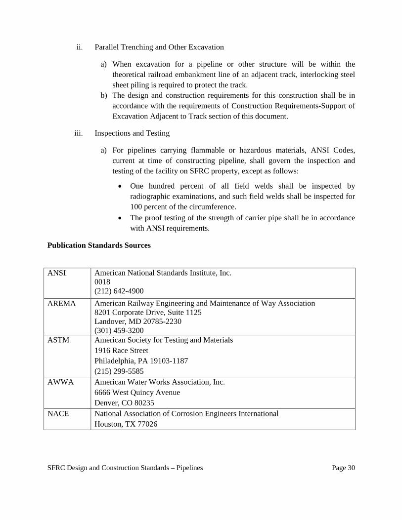
Publication Standards Sources
ANSI American National Standards Institute, Inc. 0018 (212) 642-4900
AREMA American Railway Engineering and Maintenance of Way Association 8201 Corporate Drive, Suite 1125 Landover, MD 20785-2230 (301) 459-3200
ASTM American Society for Testing and Materials 1916 Race Street Philadelphia, PA 19103-1187 (215) 299-5585
AWWA American Water Works Association, Inc. 6666 West Quincy Avenue Denver, CO 80235
NACE National Association of Corrosion Engineers International Houston, TX 77026
SFRC Design and Construction Standards – Pipelines Page 30
NOTE: If other than AREMA, ASTM, or AWWA specifications are referred to for design, materials or workmanship on the plans and specifications for the work, the copies of the applicable sections of such other specifications referred to shall accompany the plans and specifications for the work.
SFRC Design and Construction Standards – Pipelines Page 31
APPENDIX A SOUTH FLORIDA RAIL CORRIDOR
GUIDELINES FOR HORIZONTAL DIRECTIONAL DRILLING (HDD)
Preface In order to facilitate use of the latest technology available for construction of pipelines that traverse the property and track(s) owned by the Florida Department of Transportation (FDOT) for the South Florida Rail Corridor (SFRC), the following Guidelines to govern the approval and execution of pipeline and wireline occupancies utilizing Horizontal Directional Drilling (HDD) have been adopted.
Scope The guidelines detailed in this document do not nullify or supersede existing policies, standards, or practices currently approved by SFRTA.
1. For pipelines conveying gas or liquid substances, steel pipe only may be installed
under track(s) and/or SFRTA right-of-way utilizing horizontal directional drilling. 2. For wireline installations, including fiber optic cable, HDPE pipe may be installed
as the outermost pipe. Bundling is prohibited. All innerducts must have an outer casing pipe.
3. For all liquid or gas installations, or for nominal pipe sizes exceeding six (6) inches outside diameter, minimum cover (measured from base-of-rail to top-of-pipe) shall be twenty-five (25) feet, regardless of product. For fiber optics or electrical installations, with casing/conduit nominal size of six (6) inches outside diameter, or less, minimum cover shall be fifteen (15) feet.
4. Applicant submittal shall include actual planned depth of pipe under each railroad track. The plan and profile views must show the entire bore, including the sending and receiving pits, regardless of the railroad right-of-way limits.
5. Applicant must provide pipe specifications for casing and carrier pipes. Pipe must satisfy all applicable governmental and industry regulations.
6. Applicant must provide qualifications of drilling contractor, including specific instances of previous successful experience in drilling under railroad and other sensitive surface facilities.
7. Prior to commencement of drilling, the contractor must submit a Boring Plan that describes the anticipated rig capacity, the proposed equipment, and the method for advancing the bore hole through expected soil conditions , angles, depth, and exact location of the exit ditch, the pilot hole diameter, the proposed reaming plan, including the diameter of pre-reams/back-reams and diameter of the final reamed
Appendix A: SFRC Guidelines for Horizontal Directional Drilling Page 1
bore hole, and the contingency equipment and plans for dealing with soil conditions that a soil engineer could reasonably expect to be encountered at the proposed HDD installation site. The Boring Plan will also need to address the anticipated hours of operation during the HDD bore hole drilling and installation process, the minimum number of personnel, and their responsibilities on-duty and on-site during all HDD drilling operations. Consideration for working hours must be given to minimize risk to railroad operations during drilling operations. Contractor must provide a detailed Fracture Mitigation (Frac-out) Plan, including method of monitoring quantity and capturing the return of drilling fluids with particular attention to variation from proposed plan (i.e. volumes, pressure, or consistency). See Sample attached. The contractor shall establish a Survey Grid Line and provide a program of monitoring and documenting the actual location of the bore hole during drilling operations.
8. The contractor must provide a detailed Fracture Mitigation (Frac-out) Plan, including method of monitoring quantity and capturing the return of drilling fluids with particular attention to variation from proposed plan (i.e. volumes, pressure, or consistency). See Sample attached. The contractor shall establish a Survey Grid Line and provide a program of monitoring and documenting the actual location of the bore hole during drilling operations.
9. An SFRTA engineering inspector is required to monitor the ground and track for movement during the drilling, reaming, and pullback processes. The installation process and all train movement must be immediately stopped if movement of the track is detected. The damaged area must be immediately repaired. The installation process must be reviewed and modified as required and approved by SFRTA before the installation may proceed.
10. Upon completion of the HDD installation work, the contractor shall provide accu ra t e as-built drawings of the installed HDD segment. As-built drawings shall include both horizontal and profile plans. The latitude and longitude coordinates of the entry, exit, and turn points shall be provided on the as-built drawings.
Bore Plan Additional Requirements In addition to all the requirements outlined above in these Guidelines, the bore plan should include the following:
1. Pre-bore survey grid line with angles and depths defined. 2. Statement that once the bore enters SFRC property, the work will be continuous
until the drilling is complete and the pipe is pulled into place. 3. Statement that the bore will be tracked constantly, with the location and depth marked
every 10 feet. 4. If the commodity to be conveyed permits the use of HDPE pipe, it must be grade
SDR 11 or better (thicker wall). 5. The maximum size of the bore hole may not exceed Outside Diameter (O.D.) X 1.5
if O.D. is 10" or less. If the O.D. is greater than 10", the bore hole may not exceed O.D. X 1.3.
Appendix A: SFRC Guidelines for Horizontal Directional Drilling Page 2
6. A defined slurry recovery method. Disposal on SFRC property or within SFRC drainage ditches/facilities is prohibited.
7. The launching and receiving pits must be situated outside of the theoretical railroad influence line. This line begins at a point 12 feet horizontally from centerline of track, 18 inches below top-of-rail, and extends downward on a 1 ½ (H) to 1 (V) slope.
8. Statement of expected soil conditions and statement of all drill heads on site for expected and unexpected soil conditions.
9. Specifications and capacities of the bore machine. This includes: • Maximum capacities • Intended capacities • Maximum drilling RPM • Intended drilling RPM • Maximum drilling PSI • Intended drilling PSI • Maximum GPM • Intended GPM
Note that HDD is not a standard approved installation method on SFRTA right-of-way, and will require advanced engineering review and approval. Please refer to the SFRTA website for additional information.
Appendix A: SFRC Guidelines for Horizontal Directional Drilling Page 3
SAMPLE FRACTION MITIGATION CONTINGENCY PLAN FOR DIRECTIONAL DRILLING
1.0 Introduction and Purpose Directional bore operations have a potential to release drilling fluids into the surface environment through frac-outs (A frac-out is the condition where drilling mud is released through fractured bedrock into the surrounding rock and sand and travels toward the surface.) Because drilling muds consist largely of a bentonite clay-water mixture, they are not classified as toxic or hazardous substances. However, if it is released into water bodies, bentonite has the potential to adversely impact fish and invertebrates.
While drilling fluid seepage associated with a frac-out is most likely to occur near the bore entry and exit points where the drill head is shallow, frac-outs can occur in any location along a directional bore. This Frac-Out Contingency Plan (FCP) establishes operational procedures and responsibilities for the prevention, containment, and cleanup of frac-outs associated with the proposed directional drilling utility project of (Add Name of Project) ______________________________. All personnel and subcontractors are responsible for the work and must adhere to this plan during the directional drilling process. The specific objectives of this plan are to: A. Minimize the potential for a frac-out associated with directional drilling activities; B. Provide for the timely detection of frac-outs ; C. Protect the environmentally sensitive riverbed and associated riparian vegetation; D. Ensure an organized, timely, and "minimum-impact" response in the event of a frac-out
and release of drilling bentonite; and E. Ensure that all appropriate notifications are made immediately to the Owner/Applicant,
SFRTA, and appropriate regulatory agency personnel.
2.0 Description of Work: The proposed project consists of: (Add Description of Project) ________________________ Drilling operations will be halted by the drill rig operators immediately upon detection of a drop in drilling pressure or other evidence of a frac-out. The clean-up of all spills shall begin immediately. SFRTA shall be notified immediately of any spills and shall be consulted regarding clean-up procedures. A spill kit shall be on- site and used if a frac-out occurs. A vacuum truck and containment materials, such as straw bales, shall also be on-site prior to and during all operations. The contractor’s Site Supervisor/Foremen will be immediately notified. In the event of a frac-out, the Site Supervisor/Foremen will conduct an evaluation of the situation and direct recommended mitigation actions, based on the following guidelines: A. If the frac-out is minor, easily contained, has not reached the surface and is not
threatening sensitive resources, drilling operations may resume after use of a leak stopping compound or redirection of the bore;
B. If the frac-out has reached the surface, any material contaminated with bentonite shall be removed by hand to a depth of two (2) feet, contained and properly disposed of, as
Appendix A: SFRC Guidelines for Horizontal Directional Drilling Page 4
required by law. The drilling contractor shall be responsible for ensuring that the bentonite is either properly disposed of at an approved disposal facility or properly recycled in an approved manner. The Site Supervisor shall notify and take any necessary follow-up response actions in coordination with agency representatives. The Site Supervisor will coordinate the mobilization of equipment stored at off-site locations (e.g., vacuum trucks) on an as needed basis.
3.0 Site Supervisor/Foremen Responsibilities: The Site Supervisor/Foremen has overall responsibility for implementing this FCP. The Site Supervisor/Foremen will ensure that all employees are trained prior to all drilling. The Site Supervisor/Foremen shall be notified immediately when a frac-out is detected. The Site Supervisor/Foremen will be responsible for ensuring that SFRTA is aware of the frac-out, coordinating personnel, response, cleanup, regulatory agency notification and coordination to ensure proper clean-up, disposal of recovered material and timely reporting of the incident. The Site Supervisor/Foremen shall ensure all waste materials are properly containerized, labeled, and removed from the site to an approved disposal facility by personnel experienced in the removal, transport and disposal of drilling mud. The Site Supervisor/Foremen shall be familiar with all aspects of the drilling activity, the contents of this Frac-out Contingency Plan and the conditions of approval under which the activity is permitted to take place. The Site Supervisor/Foremen shall have the authority to stop work and commit the resources (personnel and equipment) necessary to implement this plan. The Site Supervisor/Foremen shall assure that a copy of this plan is available (onsite) and accessible to all construction personnel. The Site Supervisor/Foremen shall ensure that all workers are properly trained and familiar with the necessary procedures for response to a frac-out, prior to commencement of drilling operations.
4.0 Equipment: The Site Supervisor/Foremen shall ensure that: A. All equipment and vehicles are to be checked and maintained daily to prevent leaks of
hazardous materials; B. Spill kits and spill containment materials are available on-site at all times and that the
equipment is in good working order; C. Equipment required to contain and clean up a frac-out release will either be available at
the work site or readily available at an offsite location within 10 minutes of the bore site; and
D. If equipment is required to be operated near a riverbed, absorbent pads and plastic sheeting for placement beneath motorized equipment shall be used to protect the riverbed from engine fluids.
5.0 Training Prior to the start of construction, the Site Supervisor/Foremen shall ensure that the crew members receive training in the following:
A. The provisions of the Frac-out Contingency Plan, equipment maintenance and site
specific permit and monitoring requirements; B. Inspection procedures for release prevention and containment equipment and materials; C. Contractor/crew obligation to immediately stop the drilling operation upon first evidence
Appendix A: SFRC Guidelines for Horizontal Directional Drilling Page 5
of the occurrence of a frac-out and to immediately report any frac-out releases; D. Contractor/crew member responsibilities in the event of a release; E. Operation of release prevention and control equipment and the location of release
control materials, as necessary and appropriate; and F. Protocols for communication with agency representatives who might be on-site during
the clean-up effort. 6.0 Drilling Procedures The following procedures shall be followed each day, prior to the start of work. The Frac-out Contingency Plan shall be available on-site during all construction. The Site Supervisor/Foremen shall be on-site at all times that drilling is occurring or is planned to occur. The Site Supervisor/Foremen shall ensure that a Job Briefing meeting is held at the start of each day of drilling to review the appropriate procedures to be followed in case of a frac-out. The SFRTA engineering inspector shall be present at this meeting. Questions shall be answered and clarification given on any point over which the drilling crew or other project staff has concerns. Drilling pressures shall be closely monitored so they do not exceed those needed to penetrate the formation. Pressure levels shall be monitored randomly by the operator. Pressure levels shall be set at a minimum level to prevent frac-outs. During the pilot bore, maintain the drilled annulus. Cutters and reamers will be pulled back into previously-drilled sections after each new joint of pipe is added. Exit and entry pits shall be enclosed by silt fences and straw bales. A spill kit shall be on-site and used if a frac-out occurs. A vacuum truck shall be readily available on-site prior to and during all drilling operations. Containment materials (straw, silt fencing, sand bags, frac-out spill kits, etc.) shall be staged on-site at a location where they are readily available and easily mobilized for immediate use in the event of an accidental release of drilling mud (frac-out). If necessary, barriers (straw bales or sedimentation fences) between the bore site and the edge of the water source shall be constructed, prior to drilling, to prevent released bentonite material from reaching the water. Once the drill rig is in place, and drilling begins, the drill operator shall stop work whenever the pressure in the drill rig drops, or there is a lack of returns in the entrance pit. At this time the Site Supervisor/Foremen shall be informed of the potential frac-out. The Site Supervisor/Foremen and the drill rig operator(s) shall work to coordinate the likely location of the frac-out. The location of the frac-out shall be recorded and notes made on the location and measures taken to address the concern. Water containing mud, silt, bentonite, or other pollutants from equipment washing or other activities, shall not be allowed to enter a lake, flowing stream or any other water source. The bentonite used in the drilling process shall be either disposed of at an approved disposal facility or recycled in an approved manner. Other construction materials and wastes shall be recycled, or disposed of, as appropriate. The following subsections shall be adhered to when addressing a frac-out situation.
Appendix A: SFRC Guidelines for Horizontal Directional Drilling Page 6
6.1 Vacuum Truck: A vacuum truck shall be staged at a location from which it can be mobilized and relocated so that any place along the drill shot, can be reached by the apparatus, within 10 minutes of a frac-out. 6.2 Field Response to Frac-out Occurrence: The response of the field crew to a frac-out release shall be immediate and in accordance with procedures identified in this Plan. All appropriate emergency actions that do not pose additional threats to sensitive resources will be taken, as follows: A. Directional boring will stop immediately; B. The bore stem will be pulled back to relieve pressure on frac-out; C. The Site Supervisor/Foremen will be notified to ensure that SFRTA is notified,
adequate response actions are taken and notifications made; D. The Site Supervisor/Foremen shall evaluate the situation and recommend the type
and level of response warranted , including the level of notification required; E. If the frac-out is minor, easily contained, has not reached the surface and is not
threatening sensitive resources, a leak stopping compound shall be used to block the frac-out. If the use of leak stopping compound is not fully successful, the bore stem shall be redirected to a new location along the desired drill path where a frac-out has not occurred;
F. If the frac-out has reached the surface, any material contaminated with Bentonite shall be removed by hand, to a depth of 2-feet, contained and properly disposed of, as required by law. A dike or berm may be constructed around the frac-out to entrap released drilling fluid, if necessary. Clean sand shall be placed and the area returned to pre-project contours; and
G. If a frac-out occurs, reaches the surface and becomes widespread, the Site Supervisor/Foremen shall authorize a readily accessible vacuum truck and bulldozer stored off-site to be mobilized. The vacuum truck may be either positioned at either end of the line of the drill so that the frac-out can be reached by crews on foot, or may be pulled by a bulldozer, so that contaminated soils can be vacuumed up.
6.3 Response Close-out Procedures: When the release has been contained and cleaned up, response closeout activities will be conducted at the direction of the Site Supervisor/Foremen and shall include the following: A. The recovered drilling fluid will either be recycled or hauled to an approved facility
for disposal. No recovered drilling fluids will be discharged into streams, storm drains or any other water source;
B. All frac-out excavation and clean-up sites will be returned to pre-project contours using clean fill, as necessary; and
C. All containment measures (fiber rolls, straw bales, etc.) will be removed, unless otherwise specified by the Site Supervisor/Foremen.
6.4 Construction Re-start: For small releases not requiring external notification, drilling may continue, if 100 percent
Appendix A: SFRC Guidelines for Horizontal Directional Drilling Page 7
containment is achieved through the use of a leak stopping compound or redirection of the bore and the clean-up crew remains at the frac-out location throughout the construction period. For releases requiring external notification and/or other agencies, construction activities will not restart without prior approval from appropriate agencies and SFRTA. 6.5 Bore Abandonment: Abandonment of the bore will only be required when all efforts to control the frac-out within the existing directional bore have failed. 7.0 Notification: In the event of a Frac-out that reaches a water source, the Site Supervisor/Foremen will notify the appropriate resource agencies and SFRTA. All agency notifications will occur within 24 hours and proper documentation will be accomplished in a timely and complete manner. The following information will be provided: A. Name and telephone number of person reporting; B. Location of the release; C. Date and time of release; D. Type, quantity, estimated size of release ; E. How the release occurred; F. The type of activity that was occurring around the area of the frac-out; G. Description of any sensitive areas, and their location in relation to the frac-out; H. Description of the methods used to clean up or secure the site; and I. Listing of the current permits obtained for the project. 7.1 Communicating with Regulatory Agency Personnel: All employees and subcontractors will adhere to the following protocols when permitting regulatory agency personnel arrive on site. Regulatory agency personnel will be required to comply with appropriate SFRTA safety rules. Only the Site Supervisor/Foremen and the SFRTA are to coordinate communication with regulatory agency personnel. 7.2 Documentation: The Site Supervisor/Foremen shall record the frac-out event in his or her daily log. The log will include all of the information listed in Section 7.0 above. 8.0 Project Completion and Clean-up: A. All materials and any rubbish and construction debris shall be removed from the
construction zone at the end of each workday; B. Sump pits at bore entry and exits will be filled and returned to natural grade; and C. All protective measures (fiber rolls, straw bale, silt fence, etc.) will be removed unless
otherwise specified by the Site Supervisor/Foremen.
Appendix A: SFRC Guidelines for Horizontal Directional Drilling Page 8
Horizontal Directional Drilling (HDD) Bore Plan Template Failure to provide all requested information will cause a delay in processing your Application.
Bore Pipe Information:
Pipe Size (O.D.): Pipe Material & Grade: **HDPE must be grade SDR 11 or better (thicker wall)
Weight of Pipe (lb./ft.):
Equipment Information:
Proposed Equipment (Brand/Model):
Method of Drilling Fluid Recovery:
Maximum Drilling Machine Pullback Capabilities:
Minimum Drilling RPM: Maximum Drilling RPM:
Minimum Drilling PSI: Maximum Drilling PSI:
Minimum Drilling GPM: Maximum Drilling GPM:
Drilling Head Type: Dia.: in. Number/Size of Holes/Nozzles:
Back Reamer Head: Type: Dia.: in. Number/Size of Holes/Nozzles:
Drilling Head Fluid Pressure: Pilot Bore: psi/min psi/max Operating psi
Back Ream: psi/min psi/max Operating psi
Anticipated Drilling Fluid Rate: Pilot Bore: gal/min Back Ream: gal/min
Geotechnical: Soil Type: ***For bores 20” or larger; a soil boring geotechnical profile is required
Bearing Capacity: psi
Design Information: Entry Angle: Exit Angle: Depth: Base of Rail to Top of Casing: Maximum size of bore hole: ” Number and Diameter of back reams:____ ****The maximum size of the bore hole may not exceed Outside Diameter (O.D.) x 1.5 if O.D. is 10” or less. If the O.D. is greater than 10”, the bore hole may not exceed O.D. x 1.3 or 12” whichever is less. We will adopt the SFRTA’s Fraction Mitigation Contingency Plan for Directional Drilling: (Y/N)
NOTES:
1. Once the bore enters SFRC property, the work must be continuous until the drilling is complete and the pipe is pulled
in place.
2. The bore must be tracked constantly, with the location and depth marked every 10 feet.
3. All construction activities must comply with the SFRTA Guidelines for Horizontal Directional Drilling (HDD).
4. The project must comply with all conditions, obligations, and additional safety precautions required by the SFRTA.
5. Owner or Contractor shall give a minimum of 30 days advance notice to the SFRTA representative for anticipated need for flagging and inspection services. No work shall be undertaken until the SFRTA Flag Person(s) and Inspector(s) are at the job site.
6. Drilling fluid with bentonite additive is required.
7. Dry bores and wet bores (jetting) are not allowed.
Appendix A: SFRC Guidelines for Horizontal Directional Drilling Page 9