International Research Journal of Engineering and Technology (IRJET) e-ISSN: 2395 -0056 Volume: 03 Issue: 08 | Aug-2016 www.irjet.net p-ISSN: 2395-0072
Lateral Stability Analysis of High Rise Building with the Effect of
Outrigger and Belt Truss System
SYED RIZWAN NASIR1, AMARESH S. PATIL2
1Student (M.Tech), Department of Structural Engineering, PDACEG, Karnataka, India 2Associate Professor, Department of Structural Engineering, PDACEG, Karnataka, India
Abstract - The outrigger and belt truss system is one of the most efficient systems used to effectively control the excessive drift due to lateral load, so that, during small or medium lateral load due to either wind or earthquake load, the risk of structural and non-structural damage can be minimized. This paper studies the efficient use of outrigger and belt truss system for high-rise concrete building subjected to wind or earthquake load. Seven 44 storey two dimensional models of outrigger and belt truss system are subjected to wind and earthquake load, analyzed and compared to find the lateral displacement reduction related to the types of outrigger and belt system. The analysis has been carried out to study the effect and performance of outrigger system in 44 storey building. The outrigger system is provided at different levels along the height of the building. The depth of the Outrigger and belt trusses is equal to the height of the typical story and maintained same in all the models. The key parameters discussed in this paper include lateral deflection, storey drifts, base shear and fundamental time periods. Loads are considered as per Indian Standards IS: 875(Part1)-1987, IS: 875(Part2)-1987, IS: 875(Part3)-1987 and IS: 1893(Part-1) -2002. The modeling and analysis were performed using finite element software ETABS 15.2.2. Keywords: Outrigger, Belt truss system, Wind, Earthquake, Lateral displacement.
1. INTRODUCTION
Tall building development has been rapidly increasing worldwide introducing new challenges that need to be met through engineering judgment. In modern tall buildings, lateral loads induced by wind or earthquake are often resisted by a system of coupled shear walls. But when the building increases in height, the stiffness of the structure becomes more important and introduction of lateral load resisting system is used to provide sufficient lateral stiffness to the structure. The lateral load resisting system effectively control the excessive drift due to lateral load, so that, during small or medium lateral load due to either wind or earthquake load, the risk of structural and non-
structural damage can be minimized. For high-rise buildings, particularly in seismic active zone or wind load dominant, these systems are chosen as an appropriate structure. [1]
2. OUTRIGGER AND BELT TRUSS SYSTEM
Outriggers are rigid horizontal structure i.e. truss or beam which connect core wall and outer column of building to improve building strength and overturning stiffness. Outriggers have been used in tall building for nearly half century, but innovative design principle has been improving its efficiency. Outrigger system is one type of structural system which is formed from a cantilever shaped horizontal member connected to structures inner core and outer columns. Through the connection, the moment arm of the core will be increased which lead to higher lateral stiffness of the system. Central core in a building act as cantilever, outriggers are provided to reduce overturning moment in core and to transfer moment from core to outer column by connecting the core and column. Wall frame outrigger trusses is one of the most efficient and economical structures in tall building, at outer end they connected to the foundation through exterior columns. When the structure is subjected to horizontal loading, the wall and outrigger trusses will rotate, causing compression in the downwind column and tension in column on the upwind side, these axial forces will resist the rotation in the wall. [2]
The outrigger systems can be produced in any combination of steel, concrete and composite construction. Normally in steel structure outrigger are in the form of trusses and in the form of wall or deep beam in concrete structure. Outrigger may be extended to both side of central core or core may be located at one side of building with outrigger extending to other side column. Outrigger connected to core and outer column act as stiff beam under action of lateral load inducing a tension-compression couple in the outer columns, to distribute these tensile and compressive forces to a large number of exterior frame columns belt trusses are often provided.
International Research Journal of Engineering and Technology (IRJET) e-ISSN: 2395 -0056 Volume: 03 Issue: 08 | Aug-2016 www.irjet.net p-ISSN: 2395-0072
Belt truss connects outer perimeter column of a building and offer a wider perimeter to resist lateral deflection of building. This efficient structural form consists of a central core, comprising either Braced Frames or Shear Walls, with horizontal cantilever trusses or girders known as outrigger Trusses, connecting the core to the outer columns. The core may be centrally located with outriggers extending on both or it may be located on one side of the building with outriggers extending to the building columns on one side as shown in Fig.1 (a) & Fig.1 (b).
Fig -1(a): Outrigger System with a Central Core (b): Outrigger system with Offset Core.
3. OBJECTIVES OF THE STUDY
1. To study the effect of introduction of Outriggers in high rise building subjected to dynamic wind loading.
2. To study the influence of core wall and braced core wall with X braced outriggers.
3. To study the parameters with different types of Outriggers, i.e. X Bracings and V Bracings and Inverted V Bracings.
4. To study the influence of steel outrigger in comparison with concrete outrigger.
5. To study the effect of Outriggers with and without Peripheral Belt Truss.
4. MODELING AND ANALYSIS
In the present study the lateral load analysis for the RC frame building with the provision of introduction of outriggers as per seismic codes for zone V is carried out and an effort is made to study the effect of seismic loads on them and thus assess their seismic vulnerability by performing analysis.
4.1. Method of Modeling
The ETABS software is utilized to create 3D model and to carry out the analysis. The software is able to predict the behavior of space frames under static or dynamic loadings taking into account material in elasticity. The software accepts static loads as well as dynamic loads and has the ability to perform static and dynamic analysis.
4.2. Model Description
The model considered for this study is a 141.6m high rise reinforced concrete building frame. The building represents a 44 storeyed office building. The plan area of the structure is 35 X 20m with columns spaced at 5m and 4m center to center in longitudinal and transverse direction respectively. The plan layout for all the models is same as shown in Fig 2.
Fig -2: Plan layout
The models that were selected for the study are listed as follows;
• Model 1 – A Bare frame model • Model 2 – Model with Concrete Core wall and
braced Outriggers (X Bracings). • Model 3 – Model with Concrete core wall and
braced Outriggers (V Bracings). • Model 4 – Model with Concrete Core wall and
Braced Outriggers (INVERTED V bracings) • Model 5 – Model with Braced Concrete Core wall
and Braced Outriggers (X Bracings). • Model 6 – Model with Concrete Core wall and
Outriggers with Belt Truss at Periphery (X Bracings)
• Model 7 – Model with Concrete Core wall and Steel Outriggers (X bracings).
International Research Journal of Engineering and Technology (IRJET) e-ISSN: 2395 -0056 Volume: 03 Issue: 08 | Aug-2016 www.irjet.net p-ISSN: 2395-0072
According to Bryan Stafford Smith, for Optimum performance of an n-Outrigger Structure, the Outriggers are placed at 1/ (n+1), 2/ (n+1) up to the n/ (n+1) height locations.
Therefore, positions of various Outriggers for all the models are as follows: 1st Outrigger = 1/ (4+1) = 1/5= 0.2H 2nd Outrigger = 2/ (4+1) = 0.4H 3rd Outrigger = 3/ (4+1) = 0.6H 4th Outrigger = 4/ (4+1) = 0.8H
Therefore the outriggers are provided at every 10th storey.
Fig -5: Perspective view of a story at outrigger location
for various models
Table -1: Input data for all building models
Material Properties
Grade of concrete M45 for all members except columns, M60 for columns
Grade of Steel Fe 345 for steel outriggers
Young’s modulus of (M45) concrete
33.541x10⁶ KN/m2
Young’s modulus of (M60) concrete
38.729x10⁶ KN/m2
DensityofReinforcedConcrete 25 KN/m3
Poissons’s ratio of concrete 0.2
Modulus of elasticity of brick masonry
3500x103 KN/m2
Density of brick masonry 20 KN/m3
Poissons’s ratio of masonry 0.15
Member Properties
Thickness of RC slab 150mm
Column size 500mmX1000mm
Beam size 300mmX600mm
Thickness of brick masonry wall
230mm
Thickness of RC shear wall 400mm
Concrete Outriggers 300mmX1000mm
Steel Outriggers ISA 130X130X12mm
Load Intensities
Floor finishes 1.5 KN/m2
Live load on floors 3 KN/m2
Live load on roof 1.5 KN/m2
Wall load on roof level 1x0.15x20 = 3 KN/m
Wall load on all other levels (3.2-0.6)x0.23x20=12KN/m Earthquake live load on slab as per clause 7.3.1 and 7.3.2
of IS 1893 (Part-1) - 2002 is calculated as: Roof 0
International Research Journal of Engineering and Technology (IRJET) e-ISSN: 2395 -0056 Volume: 03 Issue: 08 | Aug-2016 www.irjet.net p-ISSN: 2395-0072
Chart -1: Comparison of Lateral Displacement for Load case 1.5(DL+SIDL+GY) for various models for Zone V
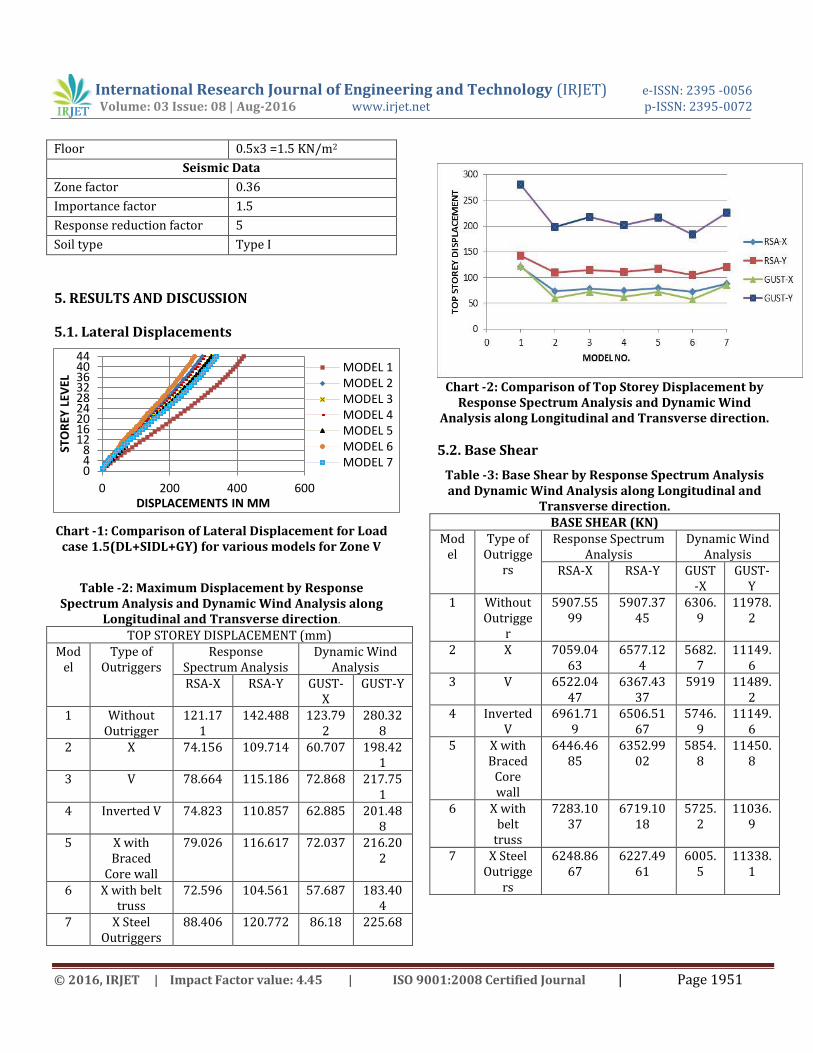
Table -2: Maximum Displacement by Response Spectrum Analysis and Dynamic Wind Analysis along
Longitudinal and Transverse direction.
TOP STOREY DISPLACEMENT (mm) Mod
el Type of
Outriggers Response
Spectrum Analysis Dynamic Wind
Analysis RSA-X RSA-Y GUST-
X GUST-Y
1 Without Outrigger
121.171
142.488 123.792
280.328
2 X 74.156 109.714 60.707 198.421
3 V 78.664 115.186 72.868 217.751
4 Inverted V 74.823 110.857 62.885 201.488
5 X with Braced
Core wall
79.026 116.617 72.037 216.202
6 X with belt truss
72.596 104.561 57.687 183.404
7 X Steel Outriggers
88.406 120.772 86.18 225.68
Chart -2: Comparison of Top Storey Displacement by Response Spectrum Analysis and Dynamic Wind
Analysis along Longitudinal and Transverse direction.
5.2. Base Shear
Table -3: Base Shear by Response Spectrum Analysis and Dynamic Wind Analysis along Longitudinal and
Transverse direction. BASE SHEAR (KN)
Model
Type of Outrigge
rs
Response Spectrum Analysis
Dynamic Wind Analysis
RSA-X RSA-Y GUST-X
GUST-Y
1 Without Outrigge
r
5907.5599
5907.3745
6306.9
11978.2
2 X 7059.0463
6577.124
5682.7
11149.6
3 V 6522.0447
6367.4337
5919 11489.2
4 Inverted V
6961.719
6506.5167
5746.9
11149.6
5 X with Braced
Core wall
6446.4685
6352.9902
5854.8
11450.8
6 X with belt
truss
7283.1037
6719.1018
5725.2
11036.9
7 X Steel Outrigge
rs
6248.8667
6227.4961
6005.5
11338.1
048
121620242832364044
0 200 400 600
STO
REY
LEV
EL
DISPLACEMENTS IN MM
MODEL 1MODEL 2MODEL 3MODEL 4MODEL 5MODEL 6MODEL 7
International Research Journal of Engineering and Technology (IRJET) e-ISSN: 2395 -0056 Volume: 03 Issue: 08 | Aug-2016 www.irjet.net p-ISSN: 2395-0072
Chart -3: Comparison of Base shear for different models by Response Spectrum Analysis & Dynamic
Wind Analysis in longitudinal direction.
Chart -4: Comparison of Base shear for different models by Response Spectrum Analysis & Dynamic
Wind Analysis in transverse direction.
5.3. Storey Drifts
Table -4: Maximum Storey Drifts by Response Spectrum Analysis and Dynamic Wind Analysis along
Longitudinal and Transverse MAXIMUM STOREY DRIFTS
Model
Type of Outriggers
Response Spectrum Analysis
Dynamic Wind Analysis
RSA-X RSA-Y GUST-X
GUST-Y
1 Without Outrigger
0.001157
0.001205
0.001222
0.002348
2 X 0.000748
0.000999
0.000606
0.001715
3 V 0.000777
0.001025
0.000714
0.001882
4 Inverted V 0.000754
0.001004
0.000628
0.001743
5 X with Braced Core
wall
0.000824
0.001062
0.000758
0.001898
6 X with belt truss
0.000745
0.000974
0.000586
0.001619
7 X Steel Outriggers
0.000849
0.001063
0.000831
0.001934
Chart -5: Comparison of Maximum Storey Drifts by Response Spectrum Analysis and Dynamic Wind
Analysis along Longitudinal and Transverse direction.
Chart -6: Comparison of maximum storey displacement for Model 1 to Model 4
02000400060008000
100001200014000
BA
SE S
HEA
R
RSA-Y
GUST-Y
0
0.0005
0.001
0.0015
0.002
0.0025
0 1 2 3 4 5 6 7
MA
X S
TOR
EY D
RIF
T MODEL NO.
RSA-Y
GUST-X
GUST-Y
RSA-X
0
50
100
150
200
250
300
RSA-X RSA-Y GUST-X
GUST-YST
OR
EY D
ISP
LAC
EMEN
TS
ANALYSIS
MODEL 1
MODEL 2
MODEL 3
MODEL 4
International Research Journal of Engineering and Technology (IRJET) e-ISSN: 2395 -0056 Volume: 03 Issue: 08 | Aug-2016 www.irjet.net p-ISSN: 2395-0072
Chart -8: Comparison of maximum storey displacement for Model 2 to Model 6
Chart -9: Comparison of maximum storey displacement for Model 2 to Model 7
5.3. Fundamental Time Periods
Chart -10: Time period vs. Modes.
6. OBSERVATIONS AND CONCLUSIONS
6.1. Observations
1. It is observed that 29.21% of top storey displacement and 26.64% of Maximum Story drift is controlled by providing X braced outriggers, 28.1% of top storey displacement and 25.44% of Maximum Story drift by Inverted V braced Outriggers and 22.32% of top storey displacement and 19.50% of Maximum Story drift is controlled with V braced outriggers.
2. Also 8.22% of displacement and 9.64% of storey drift is controlled if braced core wall is employed with X braced outriggers (Model 5) and is compared with X-braced outriggers (Model 1).
3. The model with Steel Outriggers proves to be less efficient in controlling displacement with least of only 19.49% and of storey drift by 17.27%.This observation validates the literature [10].
4. The Outriggers with Belt truss (Model 6) experienced less displacement and controlled lateral displacement by about 34.57% and about 30.75% inter storey drift is controlled.
0
50
100
150
200
250
RSA-X RSA-Y GUST-X GUST-Y
STO
REY
DIS
PLA
CEM
ENTS
ANALYSIS
MODEL 2
MODEL 6
0
50
100
150
200
250
RSA-X RSA-Y GUST-X GUST-YSTO
REY
DIS
PLA
CEM
ENTS
ANALYSIS
MODEL 2
MODEL 7
International Research Journal of Engineering and Technology (IRJET) e-ISSN: 2395 -0056 Volume: 03 Issue: 08 | Aug-2016 www.irjet.net p-ISSN: 2395-0072
5. The natural period decreases as the stiffness of the building increases and thereby leading to increase in frequency.
6. The building frame with X-braced Outriggers will have minimum possible lateral displacements in comparison to other shapes of Outriggers.
6.2. Conclusions
1. The X-braced Outriggers is very much effective; as it shows minimum lateral displacement followed by Inverted V-braced Outriggers and V-braced Outriggers.
2. The Outriggers provided with Braced core wall were less effective in reducing lateral displacement compared with Solid Core wall by a small margin, hence it can be employed as the cost effective construction.
3. The Outriggers provided in the interior frames of a building studied are found to be effective as compared to Outriggers provided in the exterior frames i.e. Belt truss.
4. The steel outriggers are found least effective compared to Concrete one. Although Steel outriggers can be employed as the light weight substitute for concrete.
5. From the study it can be concluded that wind is a dominating factor and outriggers are effective in reducing wind effect as compared earthquake forces.
6. Steel Outriggers can be used as an alternative to the other strengthening techniques available as the total weight of the existing building will remain almost same.
REFERENCES
[1]. Krunal Z. Mistry, Prof. Dhruti J. Dhyani, “Optimum outrigger location in outrigger structural system for high rise building” International Journal of Advance Engineering and Research Development Volume 2, Issue 5, May -2015. [2]. Akshay Khanorkar, Shruti Sukhdeve, S. V. Denge & S. P. Raut, “Outrigger and Belt Truss System for Tall Building to Control Deflection: A Review” GRD Journals- Global Research and Development Journal for Engineering | Volume 1 | Issue 6 | May 2016.
[3]. B.S.Taranath, “Structural Analysis & Design of Tall Buildings”, New York, McGraw Hill, 1998. [4]. M. H. Gunel, and H.E. Ilgin, A proposal for the classification of structural systems of tall buildings, Faculty of Architecture, Middle East Technical University, Ankara 06531, Turkey, 4 July 2006. [5]. Iyengar Hal, Composite and Steel High Rise Systems, Habitat and The High- Rise, Tradition & Innovation. In Proceedings of the Fifth World Congress. 14-19 May 1995.Amsterdam, The Netherlands, Bethlehem, Council on Tall Building and Urban Habitat, Lehigh University. [6]. P.S. Kian and F.T.Siahaan, “The use of outrigger and belt truss system for high-rise concrete buildings”. Dimensi Teknit Sipil, Volume 3, No1, Maret 2001, Page 36-41,ISSN1410-9530. [7]. R. S. Nair, “Belt Trusses and Basements as ‘Virtual’ Outriggers for Tall Buildings”. Engineering Journal / Fourth Quarter/ 1998. [8]. Shivacharan K, Chandrakala S, Narayana G, Karthik N.M., “Analysis of Outrigger System for Tall Vertical Irregularites Structures Subjected to Lateral Loads” IJRET: International Journal of Research in Engineering and Technology, Volume: 04 Issue: 05 | May-2015. [9]. M.R Suresh, Pradeep K.M, “Influence of Outrigger System in RC Structures for Different Seismic Zones” IJSRD - International Journal for Scientific Research & Development| Vol. 3, Issue 05, 2015 | ISSN (online): 2321-0613. [10]. Abdul Karim Mullah, Srinivas B. N, “A Study on Outrigger System in a Tall R.C Structure with Steel Bracing” International Journal of Engineering Research & Technology (IJERT), Vol. 4 Issue 07, July-2015. [11]. S. Fawzia and T. Fatima, “Deflection Control in Composite Building by Using Belt Truss and
International Research Journal of Engineering and Technology (IRJET) e-ISSN: 2395 -0056 Volume: 03 Issue: 08 | Aug-2016 www.irjet.net p-ISSN: 2395-0072
Outriggers Systems” World Academy of Science, Engineering and Technology 48 2010. [12]. Prateek N. Biradar & Mallikarjun S. Bhandiwad. “A Performance Based Study on Static and Dynamic Behavior of Outrigger Structural System for Tall Buildings” International Research Journal of Engineering and Technology (IRJET), Volume: 02 Issue: 05 | Aug-2015.
[13]. Bryan Stafford Smith and Alex Coull, “Tall Building Structures: Analysis and Design”, New York, John Willey & Sons, 1991. [14]. Indian Standard Code of Practice for Design Loads (other than earthquake) For Buildings and Structures, Part – 2 Live Loads, IS: 875 (Part 2) – 1987 (Second Revision), Bureau of Indian Standards, New Delhi, India.
[15]. Indian Standard Code of Practice for Design Loads (other than earthquake) For Buildings and Structures, Part – 3 Wind Loads, IS: 875 (Part 3) – 1987 (Second Revision), Bureau of Indian Standards, New Delhi, India. [16]. Indian Standard Criteria for Earthquake Resistant Design of Structures, IS: 1893 (Part 1) 2002, Part 1 General Provision and Buildings (Fifth Revision), Bureau of Indian Standards, New Delhi, India.