Lateral Stiffness of Masonry InfilledReinforced Concrete (RC) Frameswith Central Opening
Goutam Mondala) and Sudhir K. Jain, M.EERI
Window and door openings are inevitable parts of infill walls for functionalreasons. Currently, publications like FEMA-273 and ATC-40 containprovisions for the calculation of stiffness of solid infilled frames mainly bymodeling infill as a “diagonal strut.” However, such provisions are notprovided for infilled frames with openings. The present study proposes areduction factor for effective width of diagonal strut over that of the solidreinforced concrete (RC) infilled frame to calculate its initial lateral stiffnesswhen a central window opening is present. The study is based on initial lateralstiffness which is taken at 10% of the lateral strength of the infilled frames.�DOI: 10.1193/1.2942376�
INTRODUCTION
Performance of buildings in the recent earthquakes (e.g., 1985 Mexico City earth-quake, 2001 Bhuj earthquake) clearly illustrates that the presence of infill walls has sig-nificant structural implications. Therefore, the structural contribution of infill walls can-not simply be neglected particularly in regions of moderate and high seismicity where,the frame–infill interaction may cause substantial increase in both stiffness and strengthof the frame in spite of the presence of openings. Generally, presence of these openingsdecreases stiffness and strength of infilled frames. A review of analysis and design pro-visions related to masonry infilled RC frames in seismic design codes of different coun-tries shows that only a few codes have considered the effect of infill in analysis and de-sign of masonry infilled RC frames (Kaushik et al. 2006). On the other hand, thestiffness and strength of the infilled frames with opening are not taken care of by most ofthe codes. Hence, the behavior of infilled frames with openings needs to be studied ex-tensively in order to develop a rational approach or guidelines for design.
In the present study, a finite element (FE) analysis has been carried out on single-baysingle-story, single-bay two-story, and single-bay three-story infilled frames to examinethe effect of central openings of different sizes on the initial lateral stiffness of infilledframes. Lateral load-deflection curve of an infilled frame can be divided into three parts.In the initial part, there may be a lack of fit between frame and infill. The second part isapproximately linear and reflects the interaction between frame and infill. In the presentstudy, this stiffness has been considered assuming that this is achieved well before a loadlevel of 10% of the lateral strength of infilled frame. In the third part of lateral load-deflection relationship, a stiffness reduction may take place due to progressive degrada-
a)
Department of Civil Engineering, Indian Institute of Technology Kanpur, India 208016
tion of the infill material with increasing stress. A substantial variation of stiffness hasbeen observed in this part due to variation of material properties and failure mechanism.Because the aim of the present paper is to study the effect of opening on stiffness (ratherthan the value of stiffness as such), the stiffness degrading stage of the load-deflectioncurve is not considered. Therefore, the initial lateral stiffness is defined as the stiffness atlateral load level corresponding to 10% of the lateral strength of infilled frame. The FEmodel has been verified using experimental results of seven different specimens pub-lished in the literature. Based on the parametric study, a reduction factor is proposed todetermine the width of strut for a central opening present in an infilled frame.
The stiffness of infilled frames is influenced by the size and location of the openings.Experiments on four story steel frames with RC infills illustrated that a central openingof size 20%–30% of the panel area may reduce the stiffness by about 70%–80% in ab-sence of shear connector (Liauw 1979). Based on experimental and analytical research,it was found that an opening at either end of the loaded diagonal reduces the stiffness ofinfilled frame by about 85%–90% in comparison with infilled frame without opening(Mallick and Garg 1971). Usually, a RC band/stiffener around the opening increases thestiffness of the infilled frame. Effects of different types of RC bands/stiffeners on thestiffness of infilled frame were studied by Polyakov (1956), Dawe and Seah (1989),Jagadish et al. (1992), and Raj (2000).
Analytical models that have been developed to estimate lateral stiffness and strengthof the infilled frames with openings include the equivalent frame model, the single di-agonal strut model, and the multi-diagonal strut model. The equivalent frame model isbased on the concept of equivalent frame, where members have the properties of thecomposite sections of the actual structure (Liauw 1972, Kodur et al. 1998). The equiva-lent diagonal strut model is the most simplified yet reasonably accurate macro-model.This is usually done by modeling the infill panel as a single diagonal strut connected tothe two compressive diagonal corners. The key to this approach lies in determination ofeffective width of equivalent diagonal strut. In the last few decades, several attemptshave been made to compute the effective width of diagonal strut for infilled frames with-out opening (Holmes 1961, Smith and Carter 1969, Mainstone 1971, Liauw and Kwan1984, Paulay and Priestley 1992). The effective width of diagonal strut for infilled framewithout opening may be reduced by a reduction factor to simulate the presence of open-ings of various aspect ratios in the infilled frame (Durrani and Luo 1994, Al-Chaar2002). Multi-strut models were proposed to represent the local effects due to presence ofan opening (Thiruvengadam 1985, Buonopane and White 1999, Al-Chaar 2002).
The published researches on infilled frames point to a need for suitable quantitativedesign provisions to account for effect of openings. The expression for strut-width pro-posed by Durrani and Luo (1994) can be used to obtain the lateral stiffness of infilledframes due to presence of central opening. It was developed numerically on the basis ofFinite Element (FE) analyses only and was not verified with experimental results. Theexpression developed by Durrani and Luo are somewhat too complex for use in designoffice because these account for beam stiffness, column stiffness, and both infill andpanel aspect ratios. On the other hand, strut-width proposed by Al-Chaar (2002) is sim-pler than that proposed by Durrani and Luo (1994). It is based on both experimental and
LATERAL STIFFNESS OF MASONRY INFILLED RC FRAMES WITH CENTRAL OPENING 703
numerical research. Pushover analysis of infilled frame with openings using Al-Chaar’swidth of strut predicts in-plane strength but underestimates the initial lateral stiffness.However, modification factors have been proposed by Al-Chaar to obtain a reasonablevalue of initial stiffness directly from the pushover curve. In the present paper a simpleexpression has been developed to obtain directly the initial lateral stiffness of infilledframes with a central opening. It is based on numerical study that has been calibratedand verified with published experimental results.
METHODOLOGY
A parametric study is performed to obtain lateral stiffness of infilled frames withvarying sizes of central openings. In the study, two types of analysis methods are used:the FE method and the Single Equivalent Diagonal Strut (SEDS) method. The FE modelis first calibrated using published results of experimental specimens available in the lit-erature. This calibrated model is used in the parametric study to determine the lateralstiffness of infilled frames with openings. The width of equivalent diagonal strut for theSEDS method is estimated so as to obtain the same lateral stiffness as estimated fromthe FE method. That is, equivalent width of diagonal strut is determined that will givecorrect value of lateral stiffness. Finally, a strut-width reduction factor is proposed tomultiply the “strut-width for fully infilled panel” proposed by some researchers earlier(e.g., Paulay and Priestley 1992, Liauw and Kwan 1984 and Holmes 1961).
In the parametric study, two parameters, i.e., number of stories and size of openingsare considered. For this purpose, three sets of RC infilled frames, namely single-baysingle-story, single-bay two-story, and single-bay three-story are analyzed and their lat-eral stiffness is determined by linear elastic analysis. The single-bay single-story infilledframe considered is shown in Figure 1. All the stories of two-story and three-story in-
filled frames are identical to the single-bay single-story infilled frame. Central openingsof widths 500 mm, 1000 mm, 1500 mm, 2000 mm, 2500 mm and 3000 mm are takenone at a time for each of these three sets of infilled frames. For each of these widths ofopening, the considered heights of openings are 500 mm, 1000 mm, 1500 mm,2000 mm and 3000 mm. Furthermore, one bare frame and one fully infilled frame ofeach of these three sets of infilled frames are analyzed. Thus a total of 96 models areanalyzed in the parametric study. All the analyses are performed using the software SAP2000 Version 8 (CSI 2000a, 2000b).
Masonry of compressive prism strength 5 MPa and concrete having a characteristiccompressive strength �fck� of 25 MPa are used. The characteristic compressive strengthof concrete is specified by compressive strength of 150 mm size cube at 28 days (ex-pressed in MPa) which is almost 1.25 times the 28 day compressive strength of concretecylinder specified in ACI 318-05 (2005). Poisson’s ratios of masonry and concrete aretaken as 0.18 and 0.20, respectively. All the models are analyzed by applying lateral loadin combination with gravity load. Lateral loads are taken as 10% of the lateral strengthof the frames (Choubey and Sinha 1994) and are applied at the floor level as in the ex-perimental models. Lateral strength of frames is estimated by the pushover analysis byusing the modified diagonal strut model (Al-Chaar 2002).
FINITE ELEMENT (FE) ANALYSIS
In the FE method, standard two-noded frame elements with two translational degreesof freedom and one rotational degree of freedom at each node are used to model theframe elements. The infills are idealized by four-noded plane stress rectangular or squarearea elements with two translational degrees of freedom at each node (Figure 2). Inter-face of the infill and frame are modelled using linear springs incapable of taking anytension. Similar elements were also used earlier by some investigators, e.g., Thiruven-gadam (1985).
Figure 2. FE modeling of single-bay, single-story infilled frame with opening.
LATERAL STIFFNESS OF MASONRY INFILLED RC FRAMES WITH CENTRAL OPENING 705
CALIBRATION OF THE FE MODEL
Experimental results available in the published literature for two RC bare frames,three RC infilled frames without any opening, and two RC infilled frames with centralwindow openings are used to calibrate the FE model (Table 1). The influence of the fol-lowing four factors namely, �a� flexural rigidity of components �b� modulus of elasticityof masonry, �c� rigidity of beam-column junction, and �d� the separation between frameand infill are examined in the FE analysis. Results of initial lateral stiffness by FE modelare compared with experimental initial lateral stiffness and based on these comparisonsa FE model is chosen for the subsequent parametric study. Cracking in infill and frameis not considered since the stiffness has been considered at a load level corresponding to10% of the lateral strength of infilled frame. Since the present study focuses on the ef-fect of opening on initial lateral stiffness of infilled frame, failure mode and materialproperties are not important parameters. Therefore, these parameters are not consideredin the present study.
Flexural Rigidity of Components
In flexure dominated components (e.g., beams, columns, etc.), effective cross sectionof the member is reduced significantly due to the appearance of flexure cracks. There-fore, in the present study, two types of flexural rigidity of components are taken, namelyflexural rigidity of components considering uncracked section and cracked section. Un-cracked flexural rigidity of components is taken as EcIg, where Ig is the gross cross sec-tion of the components and Ec is the modulus of elasticity of concrete as per IS 456:2000:
Table 1. Comparison of finite element analysis and experimental values for initial lateralstiffnessa
Stiffness (kN/mm)
Model No. Authors Type of Specimen FEA ExperimentalError(%)
1 Choubey and Sinha (1994) 1-Story 1-Bay Bare Frame 3.8 3.9 −2.42 Pillai (1995) 5-Story 1-Bay Bare Frame 3.9 4.4 −20.73 Choubey and Sinha (1994) 1-Story 1-Bay Infilled Frame
without Opening37.9 25.4 49.3
4 Al-Chaar et al. (2002) 1-Story 1-Bay Infilled Framewithout Opening
a Semirigid end-offset, cracked flexural rigidity of components, Em=550fm, and frame-infill separation are con-sidered.
706 G. MONDAL AND S. K. JAIN
Ec = 5000�fck, �1�
where fck is the characteristic compressive strength (MPa) of concrete cube at 28 days.Cracked flexural rigidity of components is taken as 0.5EcIg in beam and in tension col-umn and 0.7EcIg in compression column, where Ec is the modulus of elasticity (Equa-tion 1) (ATC-40 1996, and FEMA-273 1997). For the specimens 2 and 5, the modulus ofelasticity of concrete has been reported based on compressive tests on concrete cubes;these are used in separate cases.
Modulus of Elasticity of Masonry
Drysdale et al. (1993) have recommended that modulus of elasticity of masonry maybe taken as:
Em = kfm, �2�
where fm is the compressive strength of masonry prism in MPa and k lies between 500 to600. In the present study, this expression is used with k taken as 550 to model the initialstiffness of the infilled frames with openings.
Rigidity of Beam-Column Junction
In RC structures, the assumption of centerline dimensions is often inaccurate. Finitesize of the joint can be modelled through the use of rigid-end-offsets option. In fact,rigid-end-offsets allow modeling the ends of a member such that these are not consid-ered to be part of the flexible portion. In the present study, three types of rigidity of thebeam-column joints namely, rigid, semirigid, and flexible are used to investigate the ef-fect of finite size of the joint (Figure 3). In case of rigid beam-column joint, the end-offset is up to half column depth along beam from center line of column and half beamdepth along column from center line of beam. In case of semirigid beam-column joint,rigid end-offset is upto quarter column depth along beam from center line of column andquarter beam depth along column from center line of beam while, in case of flexiblebeam-column joint, length of rigid end-offset is taken as zero.
Figure 3. Modelling of beam-column joint-end-offsets: (a) rigid end-offset, (b) semirigid end-offset, and (c) flexible end-offset.
LATERAL STIFFNESS OF MASONRY INFILLED RC FRAMES WITH CENTRAL OPENING 707
Frame and Infill Interface
In the present study, two types of frame-infill interface are considered. In the firsttype, separation between frame and infill is not allowed while in the second type, sepa-ration between frame and infill at the non-loaded diagonal is allowed. To account forthis, linear springs are used as interface elements. Stiffness of the spring is the axialstiffness of mortar, i.e., AmorEmor / tm where, Amor is the effective area of mortar, tm is thethickness of mortar, and Emor is the modulus of elasticity of mortar. In absence of spe-cific data on modulus of elasticity of the mortar, it is taken same as modulus of elasticityof masonry (i.e., Em=550fm). As the mortar is weak in tension, its tensile strength isneglected in the FE analysis. For a given lateral load, the forces in these link elementsare evaluated and those carrying tension are removed. The process is repeated till all thelinks remaining are in compression and the contact lengths are established. Due to un-availability of reliable data on stiffness of mortar it was assumed that the axial stiffnessof mortar and brick is comparable. Hence, after identifying the length of contact, thelink elements are done away with and the infill is extended to the centerline of the frameat the contact portion and the frames are analyzed to obtain the lateral stiffness. Thisslightly increases the overall stiffness of infilled frames.
Results
Results of the bare frames, i.e., specimen 1 and 2 show that the uncracked flexuralrigidity of components results in up to 120% error (average 70%). Models with flexiblebeam-column joints show up to 50% error with an average of 26%. On the other hand,the models involving the combination of cracked flexural rigidity of components andrigid and semirigid beam-column joints result in maximum 20% error with an averageerror of 10%.
Analysis of infilled frames, i.e., specimen 3, 4 and 5 shows that the modulus of elas-ticity of masonry based on Drysdale et al.’s (1993) empirical formula (Equation 2)yields reasonable estimate of the initial lateral stiffness. Complete contact between theframe and the infill resulted in large error in initial lateral stiffness, as large as 300%.Therefore, the separation between frame and infill at the non-loaded diagonal proved tobe a significant factor. Use of these two parameters along with the cracked flexural ri-gidity of components and semirigid beam-column joint, as discussed above, give thebest correlation with experimental values of lateral stiffness; difference being up to 57%(with an average of 38%). Therefore, this combination is considered for analysis of in-filled frames with openings.
Use of the above mentioned parameters on infilled frames with openings resulted inless than 10% error in initial stiffness as compared to the experimental initial lateralstiffness. Therefore, results of the models considering cracked flexural rigidity of com-ponents, semirigid beam-column joint, and separation between frame and infill at thenon-loaded diagonal are summarized in Table 1. Detailed results of all the other modelsare available elsewhere (Mondal 2003).
Figure 4 shows bar diagram of difference between FE model and experimental valueof initial lateral stiffness for specimen 3, 4, 5, 6 and 7. Specimen 1 and 2 are not in-
708 G. MONDAL AND S. K. JAIN
cluded in the comparison since these are bare frames, where comparison of separation offrame and infill at non-loaded diagonal is meaningless. Comparisons of Figures 4a–4cwith Figures 4d–4f, and Figures 4g–4i with Figures 4j–4l show that separation of frame-infill interface at the non-loaded diagonal should be considered. Similarly, comparisonsof Figures 4a–4c with Figures 4g–4i, and Figures 4d–4f with Figures 4j–4l indicate thatcracked flexural rigidity of components should be taken in the analysis. This figure alsoindicates that semirigid beam-column junction minimizes difference between FE modeland experimental value of initial lateral stiffness. On the whole, Figure 4k gives the best
Figure 4. Comparison of different FE models. (UC: uncracked flexural rigidity of components;C: cracked flexural rigidity of components; F: flexible end-offset; SR: semirigid end-offset; R:rigid end-offset; NS: no separation at the frame-infill interface; S: separation at the frame-infillinterface).
LATERAL STIFFNESS OF MASONRY INFILLED RC FRAMES WITH CENTRAL OPENING 709
match between FE model and experimental results; this model considers cracked flex-ural rigidity of components, semirigid beam-column junction and separation of frame-infill interface at non-loaded diagonal.
PARAMETRIC STUDY USING CALIBRATED FE MODEL
The initial lateral stiffness of single-bay single-story, single-bay two-story, andsingle-bay three-story RC infilled frames with varying sizes of central openings are de-termined using calibrated FE model. Cracked flexural rigidity of components, semirigidbeam column junction and frame-infill separation are considered in the analysis. The RCbeams and columns are discretized as frame elements and the infill as 250 mm�250 mm plane stress elements (Figure 2). A lateral load is applied at the roof level incombination with gravity load.
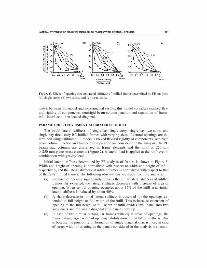
Initial lateral stiffness determined by FE analysis of frames is shown in Figure 5.Width and height of opening is normalized with respect to width and height of infill,respectively, and the lateral stiffness of infilled frames is normalized with respect to thatof the fully infilled frames. The following observations are made from the analysis:
(a) Presence of opening significantly reduces the initial lateral stiffness of infilledframes. As expected, the lateral stiffness decreases with increase of area ofopening. When central opening occupies about 15% of the infill area, initiallateral stiffness is reduced by about 40%.
(b) A sharp decrease in initial lateral stiffness is observed for the openings ex-tended to full height or full width of the infill. This is because extension ofopening to the full height or full width of infill divides infill panel into twosub-panels and the single diagonal strut cannot develop.
(c) In case of two similar rectangular frames with equal areas of openings, theframe having larger width of opening exhibits more initial lateral stiffness. Thisis because the possibility of formation of single diagonal strut is more in caseof larger width of opening as the panels considered in the analysis are rectan-
Figure 5. Effect of opening size on lateral stiffness of infilled frame determined by FE analysis:(a) single-story, (b) two-story, and (c) three-story.
Figure 6. Formation of diagonal strut: (a) single diagonal strut, (b) multi-strut.
710 G. MONDAL AND S. K. JAIN
Table 2. Effect of dimensions of opening on initial lateral stiffness of infilled frame
Width Smaller than Height Width Larger than Height
LATERAL STIFFNESS OF MASONRY INFILLED RC FRAMES WITH CENTRAL OPENING 711
gular �5000 mm�3000 mm� (Figure 6). As the height of opening increasesthe panel is divided into two sub-panels which increase the possibility of for-mation of multi-strut as shown in Figure 6.
(d) For the same area of opening if the dimensions of opening vary, the differencein initial stiffness is less than 10% (Table 2). Hence, except in extreme cases,area of opening (and not the height-to-width ratio of opening) governs the lat-eral stiffness of infilled frame. Therefore, the reduction factor proposed in thisarticle does not depend upon the height to width ratio of the opening.
SINGLE EQUIVALENT DIAGONAL STRUT (SEDS) ANALYSIS
Initial lateral stiffness of the three identical infilled frames (namely single-story, two-story and three-story) is also obtained by SEDS analysis. In this analysis, infills aremodelled as single equivalent diagonal struts and the widths of diagonal struts are takenas 0.001d, 0.01d, 0.025d, 0.05d, 0.1d, 0.15d, 0.2d, 0.25d, 0.3d, 0.4d and 0.5d, where din the diagonal length of infill. The strut is connected to the diagonal nodes at the beam-column joint so that it can take only axial force. The thickness of the struts is kept sameas that of the infill. The beams and columns are modelled as frame elements. Semirigidend-offsets are considered to account for the finite size of beam-column junctions.Cracked flexural rigidity of components and modulus of elasticity of masonryEm=550fm are considered for the analysis.
The effect of strut-width on lateral stiffness of the infilled frames is shown in Figure7. It is seen that the lateral stiffness of infilled frames increases almost linearly with in-crease in strut-width.
Figure 7. Effect of width of equivalent diagonal strut determined by single equivalent diagonalstrut analysis on lateral stiffness: (a) single-story, (b) two-story, and (c) three-story.
712 G. MONDAL AND S. K. JAIN
STRUT-WIDTH REDUCTION FACTOR
The effect of opening on the lateral stiffness of the infilled frame can be representedby a diagonal strut of reduced width. This reduction in strut-width can be represented bya factor ��w�, which is defined as ratio of reduced strut-width to strut-width correspond-ing to fully infilled frame, i.e.,
Strut − width reduction factor ��w�
=Strut − width of Infilled Frame with Opening �wdo�
Strut − width of Fully Infilled Frame �wds��3�
For an infilled frame with a given size of opening, strut width required to obtain thelateral stiffness can be evaluated from Figure 8. From this figure, strut-widths are ob-tained for single-story, two-story, and three-story infilled frames with openings, consid-ered in the present study. For example, in Figure 8, width of equivalent diagonal strut is
about 0.15d forl0
L =0.6 andh0
H =0.33, regardless of the number of stories.
Area of opening, Aop, is normalized with respect to area of infill panel, Ainfill, and theratio is termed as opening area ratio, �co, i.e.,
Opening-Area-Ratio ��co� =Area of Opening �Aop�Area of Infill �Ainfill�
�4�
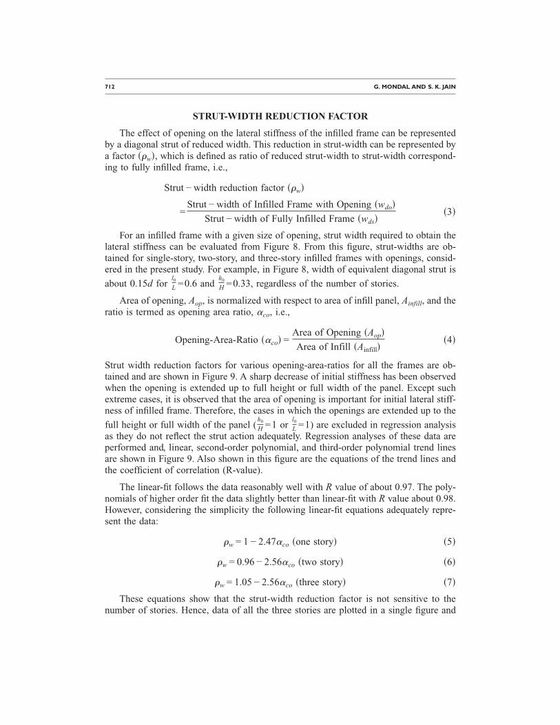
Strut width reduction factors for various opening-area-ratios for all the frames are ob-tained and are shown in Figure 9. A sharp decrease of initial stiffness has been observedwhen the opening is extended up to full height or full width of the panel. Except suchextreme cases, it is observed that the area of opening is important for initial lateral stiff-ness of infilled frame. Therefore, the cases in which the openings are extended up to the
full height or full width of the panel (h0
H =1 orl0
L =1) are excluded in regression analysisas they do not reflect the strut action adequately. Regression analyses of these data areperformed and, linear, second-order polynomial, and third-order polynomial trend linesare shown in Figure 9. Also shown in this figure are the equations of the trend lines andthe coefficient of correlation (R-value).
The linear-fit follows the data reasonably well with R value of about 0.97. The poly-nomials of higher order fit the data slightly better than linear-fit with R value about 0.98.However, considering the simplicity the following linear-fit equations adequately repre-sent the data:
�w = 1 − 2.47�co �one story� �5�
�w = 0.96 − 2.56�co �two story� �6�
�w = 1.05 − 2.56�co �three story� �7�
These equations show that the strut-width reduction factor is not sensitive to thenumber of stories. Hence, data of all the three stories are plotted in a single figure and
LATERAL STIFFNESS OF MASONRY INFILLED RC FRAMES WITH CENTRAL OPENING 713
Figure 8. Effect of opening size on equivalent diagonal strut: (a) single-story, (b) two-story, and
(c) three-story.
714 G. MONDAL AND S. K. JAIN
regression analysis is performed on the combined data. A linear-fit curve (�w=0.99−2.58�co, with R=0.965) follows the trend of data reasonably well (Figure 10). Basedon the above equations and linear fit curve, the reduction factor for the infilled framewith opening can be simplified as:
Figure 9. Effect of opening-area-ratio on strut-width reduction factor: best fit curves of ana-lytical results (a) single-story, (b) two-story, and (c) three-story.
LATERAL STIFFNESS OF MASONRY INFILLED RC FRAMES WITH CENTRAL OPENING 715
�w = 1 − 2.6�co �8�
regardless of the number of stories. The above expression for the reduction factor (i.e.,�w=1−2.6�co) is also plotted in Figure 10. The comparison between this curve and thelinear fit curve shows that the proposed equation (Equation 8) is a good estimation ofinitial lateral stiffness of the infilled frame with a central opening.
Thus one may conclude that the stiffness contribution of infill may be neglectedwhen opening area is greater that 40% of the area of infill. Similarly, presence of open-ing may be ignored if it is less than 5% of area of infill panel.
WIDTH OF STRUT
The reduction factor proposed above is with respect to analytical strut-width for fullyinfilled frame. In practice, one may use strut-width of solid infilled frames based on anumber of equations available in the literature, each giving a different value of lateralstiffness. There has been a concern by some researchers (Meharbi et al. (1994), Al-Chaar (2002), and Al-Chaar et al. (2003a, 2003b)) that the single equivalent diagonalstrut does not predict satisfactorily the lateral stiffness of infilled frame. It is thereforeimportant to compare the width of diagonal strut of solid infilled frames obtained fromseveral empirical relationships available in the literature with that obtained by the finiteelement analysis. The following relations have been considered:
wds = 0.58� l
h�−0.445
��H�0.335d� lh �0.064
�Smith and Carter 1969� �9�
Figure 10. Linear trend line of all the merged data and comparison with the proposed equationof strut-width reduction factor.
716 G. MONDAL AND S. K. JAIN
wds = 0.175��H�−0.4d �Mainstone 1971� �10�
wds =d
4�Paulay and Priestley1992� �11�
wds =�0.95h cos ��
��H�Liauw and Kwan 1984� �12�
wds =d
3�Holmes 1961� �13�
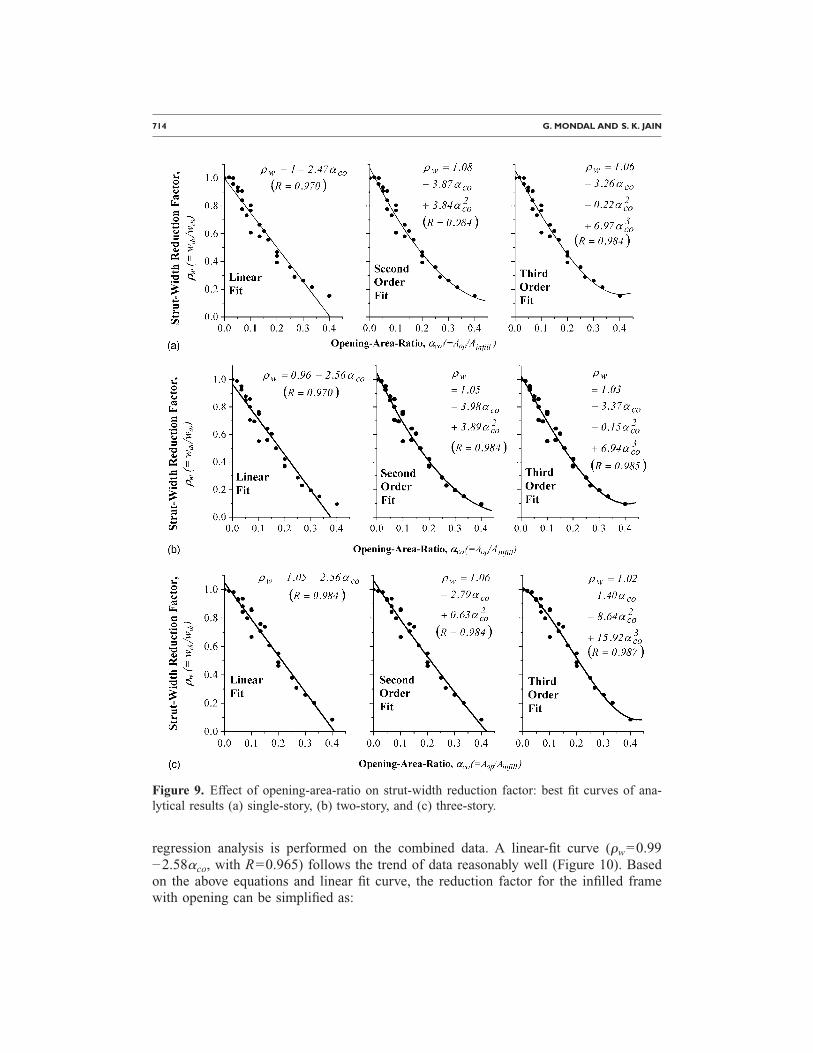
In Table 3 the widths of struts for single-story, two-story, and three-story solid infill, cal-culated by the Equations 9–13, are compared with the widths of struts determined by FEmethod. The difference in width of strut from FE analysis and that using Equation 9(Smith and Carter 1969) is up to 150%. Strut width proposed by Mainstone (1971) sub-stantially underestimates the lateral stiffness of infilled frames (the strut width proposedby Mainstone is 60% to 70% smaller than that found from FE analysis) which supportsthe conclusion of Meharbi et al. (1994, 2003). Therefore, the proposed reduction factorcannot be applied to widths of struts proposed by Smith and Carter (1969), and Main-stone (1971). However, results from Equations 11–13 (Paulay and Priestley 1992, Liauwand Kwan 1984, and Holmes 1961) compare well with the strut widths from FE analy-sis. Hence, only these three proposals are considered for further discussion.
New strut-width reduction factor values are calculated wherein the strut-width ofsolid infill �wds� is based on Equations 11, 12 or 13. Two linear-fits are considered, oneis the best fit and the other a constrained fit with the �w-intercept forced to be unity (Fig-ure 11). Poor correlations are obtained for strut-width reduction factor values fromEquations 11 (Paulay and Priestley 1992) and 12 (Liauw and Kwan 1984). On the otherhand, the width of strut using Equation 13 (Holmes 1961) provides the best results forthe proposed strut-width reduction factor for infilled frames with openings. The twoequations for unconstrained fit ��w=0.96−2.44�co ,R=0.928� and constrained fit��w=1−2.62�co ,R=0.924� match very well (Figure 11). Furthermore, the constrainedfit curve is very close to the proposed strut-width reduction factor (i.e., �w=1−2.6�co).
Table 3. Comparison of width of equivalent diagonal strut for infilled frame without opening
LATERAL STIFFNESS OF MASONRY INFILLED RC FRAMES WITH CENTRAL OPENING 717
Therefore, the strut-width for solid infill as per Equation 13 (Holmes 1961) can be takenas the basis to apply the proposed strut-width reduction factor due to presence ofopening.
VERIFICATION OF THE PROPOSED REDUCTION FACTOR
In the parametric study, all the parameters except the number of stories and the sizeof openings are kept constant for different models. Based on this, a reduction factor forinfilled frames with openings is proposed. To demonstrate the applicability of the pro-posed reduction factor, some of the parameters of the single-bay single-story model arechanged one at a time while all others are kept constant. In addition, results of experi-mental specimens available in the literature are considered to verify the proposed strut-width reduction factor. Moreover, the proposed strut-width reduction factor is comparedwith that proposed by Durrani and Luo (1994), and by Al-Chaar (2002).
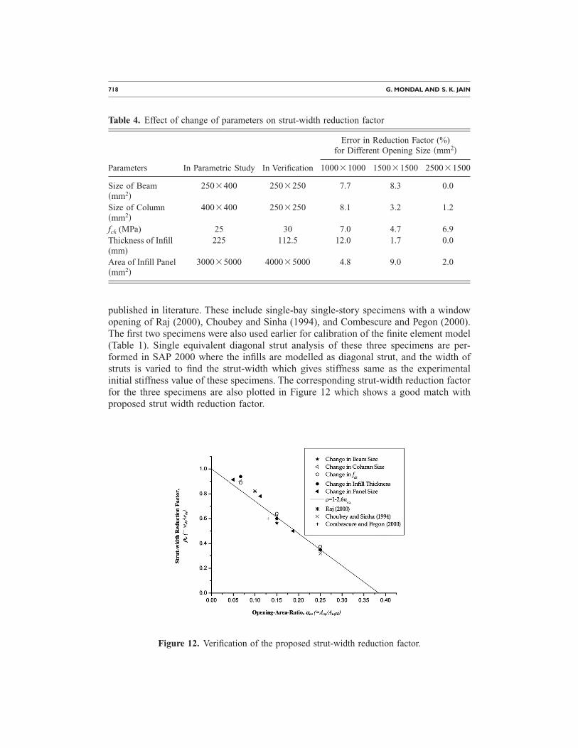
The effects of the sizes of beam and column, compressive strength of concrete,thickness and area of infill panel on strut-width reduction factor are shown in Table 4. Itis seen that a 37.5% reduction in size of beam results in 8% error in the strut-widthreduction factor. Similarly, 70% reduction in size of column leads to 8% error in reduc-tion factor. A 7% error in reduction factor was observed due to a 20% increase in thecompressive strength of concrete. Table 4 also displays that reduction factor is weaklydependent on thickness and area of infill panel. All these strut-width reduction factorsare also plotted in Figure 12 along with the proposed strut-width reduction factor as perEquation 8, which shows that there is not much variation in the reduction factor in re-lation to the changes made in the parameters.
The proposed reduction factor is further verified with three experimental specimens
Figure 11. Strut-width reduction factor based on available strut-width for solid infill.
718 G. MONDAL AND S. K. JAIN
published in literature. These include single-bay single-story specimens with a windowopening of Raj (2000), Choubey and Sinha (1994), and Combescure and Pegon (2000).The first two specimens were also used earlier for calibration of the finite element model(Table 1). Single equivalent diagonal strut analysis of these three specimens are per-formed in SAP 2000 where the infills are modelled as diagonal strut, and the width ofstruts is varied to find the strut-width which gives stiffness same as the experimentalinitial stiffness value of these specimens. The corresponding strut-width reduction factorfor the three specimens are also plotted in Figure 12 which shows a good match withproposed strut width reduction factor.
Table 4. Effect of change of parameters on strut-width reduction factor
Error in Reduction Factor (%)for Different Opening Size �mm2�
Parameters In Parametric Study In Verification 1000�1000 1500�1500 2500�1500
Size of Beam�mm2�
250�400 250�250 7.7 8.3 0.0
Size of Column�mm2�
400�400 250�250 8.1 3.2 1.2
fck (MPa) 25 30 7.0 4.7 6.9Thickness of Infill(mm)
225 112.5 12.0 1.7 0.0
Area of Infill Panel�mm2�
3000�5000 4000�5000 4.8 9.0 2.0
Figure 12. Verification of the proposed strut-width reduction factor.
LATERAL STIFFNESS OF MASONRY INFILLED RC FRAMES WITH CENTRAL OPENING 719
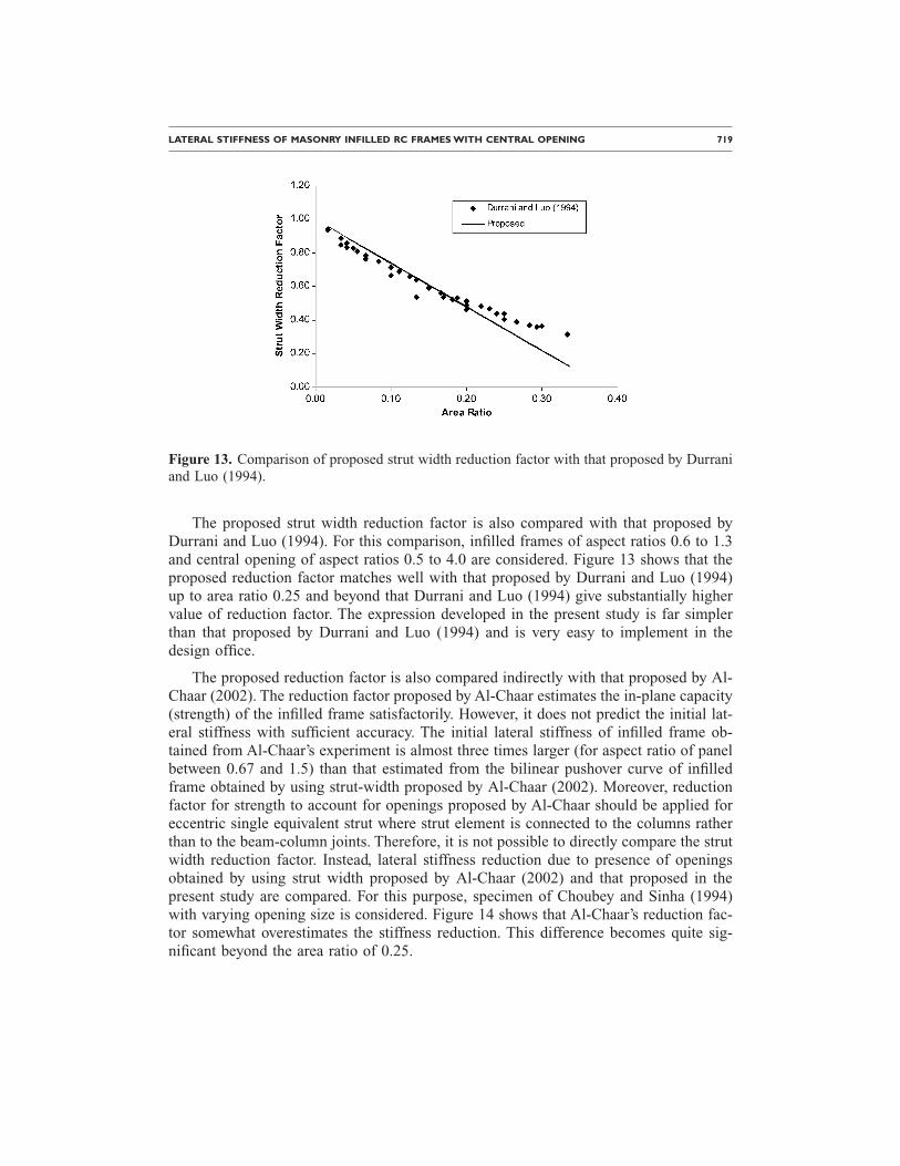
The proposed strut width reduction factor is also compared with that proposed byDurrani and Luo (1994). For this comparison, infilled frames of aspect ratios 0.6 to 1.3and central opening of aspect ratios 0.5 to 4.0 are considered. Figure 13 shows that theproposed reduction factor matches well with that proposed by Durrani and Luo (1994)up to area ratio 0.25 and beyond that Durrani and Luo (1994) give substantially highervalue of reduction factor. The expression developed in the present study is far simplerthan that proposed by Durrani and Luo (1994) and is very easy to implement in thedesign office.
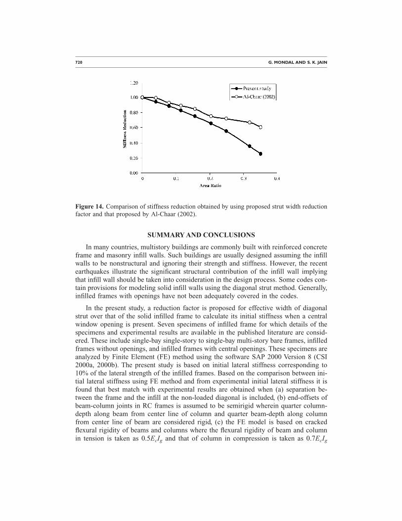
The proposed reduction factor is also compared indirectly with that proposed by Al-Chaar (2002). The reduction factor proposed by Al-Chaar estimates the in-plane capacity(strength) of the infilled frame satisfactorily. However, it does not predict the initial lat-eral stiffness with sufficient accuracy. The initial lateral stiffness of infilled frame ob-tained from Al-Chaar’s experiment is almost three times larger (for aspect ratio of panelbetween 0.67 and 1.5) than that estimated from the bilinear pushover curve of infilledframe obtained by using strut-width proposed by Al-Chaar (2002). Moreover, reductionfactor for strength to account for openings proposed by Al-Chaar should be applied foreccentric single equivalent strut where strut element is connected to the columns ratherthan to the beam-column joints. Therefore, it is not possible to directly compare the strutwidth reduction factor. Instead, lateral stiffness reduction due to presence of openingsobtained by using strut width proposed by Al-Chaar (2002) and that proposed in thepresent study are compared. For this purpose, specimen of Choubey and Sinha (1994)with varying opening size is considered. Figure 14 shows that Al-Chaar’s reduction fac-tor somewhat overestimates the stiffness reduction. This difference becomes quite sig-nificant beyond the area ratio of 0.25.
Figure 13. Comparison of proposed strut width reduction factor with that proposed by Durraniand Luo (1994).
720 G. MONDAL AND S. K. JAIN
SUMMARY AND CONCLUSIONS
In many countries, multistory buildings are commonly built with reinforced concreteframe and masonry infill walls. Such buildings are usually designed assuming the infillwalls to be nonstructural and ignoring their strength and stiffness. However, the recentearthquakes illustrate the significant structural contribution of the infill wall implyingthat infill wall should be taken into consideration in the design process. Some codes con-tain provisions for modeling solid infill walls using the diagonal strut method. Generally,infilled frames with openings have not been adequately covered in the codes.
In the present study, a reduction factor is proposed for effective width of diagonalstrut over that of the solid infilled frame to calculate its initial stiffness when a centralwindow opening is present. Seven specimens of infilled frame for which details of thespecimens and experimental results are available in the published literature are consid-ered. These include single-bay single-story to single-bay multi-story bare frames, infilledframes without openings, and infilled frames with central openings. These specimens areanalyzed by Finite Element (FE) method using the software SAP 2000 Version 8 (CSI2000a, 2000b). The present study is based on initial lateral stiffness corresponding to10% of the lateral strength of the infilled frames. Based on the comparison between ini-tial lateral stiffness using FE method and from experimental initial lateral stiffness it isfound that best match with experimental results are obtained when (a) separation be-tween the frame and the infill at the non-loaded diagonal is included, (b) end-offsets ofbeam-column joints in RC frames is assumed to be semirigid wherein quarter column-depth along beam from center line of column and quarter beam-depth along columnfrom center line of beam are considered rigid, (c) the FE model is based on crackedflexural rigidity of beams and columns where the flexural rigidity of beam and columnin tension is taken as 0.5EcIg and that of column in compression is taken as 0.7EcIg
Figure 14. Comparison of stiffness reduction obtained by using proposed strut width reductionfactor and that proposed by Al-Chaar (2002).
LATERAL STIFFNESS OF MASONRY INFILLED RC FRAMES WITH CENTRAL OPENING 721
(ATC-40 1996), (d) modulus of elasticity of concrete �Ec� is assumed as Ec=5000�fck,where fck is the characteristic compressive strength (MPa) of concrete cube at 28 days,and (e) modulus of elasticity of masonry is taken as Em=550fm (Drysdale et al. 1993),where fm is the compressive strength of masonry prism in MPa. Based on such a FEmodel, parametric study is performed for single-bay single-story, single-bay two-storyand single-bay three-story infilled frames with different opening sizes.
It was proposed that in the single diagonal strut model of fully infilled frame, thewidth of the strut can be taken as one third of the diagonal length of the infill as pro-posed by Holmes (1961). The presence of central opening can be considered by reducingthe effective width through a reduction factor, �w=1−2.6�co, where �co=ratio of thearea of opening to the area of the infill. The applicability of this proposed reduction fac-tor is verified by varying some of the parameters that are kept constant during the para-metric study and with three experimental specimens; these show good agreement.
It can also be concluded that the effect of opening on the initial lateral stiffness ofinfilled frames should be neglected if the area of opening is less than 5% of the area ofthe infill panel, and the strut-width reduction factor should be set to one, i.e., the frameis to be analyzed as a solid infilled frame. The effect of infill on the initial lateral stiff-ness of infilled frame may be ignored if the area of opening exceeds 40% of the area ofthe infill panel, and the strut-width reduction factor should be set to zero, i.e., the frameis to be analyzed as a bare frame. The proposed reduction factor is applicable for infilledframe with normal openings. Extreme cases where openings are extended to full heightor full width of the infilled frame cannot be covered by the proposed reduction factor.
The present study is limited to infilled frames with central openings. Future workshould be performed to obtain the effect of location of opening in the infilled frame. Theeffect of lintel bands or different types of stiffeners on the reduction factor should alsobe investigated.
REFERENCES
American Concrete Institute (ACI), 2005. ACI 318-05: Building Code Requirements for Struc-tural Concrete, ACI Committee 318, Farmington Hills, Michigan, 430 pp.
Al-Chaar, G., 2002. Evaluating strength and stiffness of unreinforced masonry structures,ERDC/CERL TR-02-1, US Army Corps of Engineers, Construction Engineering ResearchLaboratories.
Al-Chaar, G., Issa., M., and Sweeney, S., 2002. Behavior of masonry-infilled nonductile rein-forced concrete frames, J. Struct. Eng., ASCE 128, 1055–1063.
Al-Chaar, G., Lamb, G. E., and Abrams, D. P., 2003a. Effects of openings on structural perfor-mance of unreinforced masonry infilled frames, Proceedings, Ninth North American Ma-sonry Conference, Clemson University, Canada.
Al-Chaar, G., Lamb, G. E., and Issa, M. A., 2003b. Effects of openings on structural perfor-mance of unreinforced masonry infilled frames, in Large Scale Structural Testing, Issa, M.A. and Mo, Y. L., eds., American Concrete Institute, SP-211.
Applied Technology Council (ATC), 1996. Seismic Evaluation and Retrofit of Concrete Build-ings, volumes 1 and 2, Report No. ATC-40, Redwood City, CA.
722 G. MONDAL AND S. K. JAIN
Buonopane, S. G., and White, R. N., 1999. Pseudodynamic testing of masonry infilled rein-forced concrete frame, J. Struct. Eng., ASCE 125, 578–589.
Bureau of Indian Standards (BIS), 2000. Indian Standard Code of Practice for Plane and Re-inforced Concrete, IS:456-2000, 4th revision, Bureau of Indian Standards, New Delhi.
Choubey, U. B., and Sinha, S. N., 1994. Cyclic response of infilled frames, J. Struct. Eng.,SERC Chennai 21, 203–211.
Combescure, D., and Pegon, P., 2000. Application of the local to global approach to the study ofinfilled frame structures under seismic loading, Proceedings, Twelfth World Conference onEarthquake Engineering, CD ROM Paper No. 0505, Auckland, New Zealand.
CSI, 2000a. Integrated Software for Structural Analysis and Design: Analysis ReferenceManual, Computer and Structures, Inc., Berkeley, CA.
––—, 2000b. Integrated Software for Structural Analysis and Design: Getting Started, BasicAnalysis Reference and Introductory Tutorial, Computer and Structures, Inc., Berkeley, CA.
Dawe, J. L., and Seah, C. K., 1989. Behavior of masonry infilled steel frames, Can. J. Civ. Eng.16, 865–876.
Drysdale, R. G., Hamid, A. A., and Baker, R. L., 1993. Masonry Structures: Behavior and De-sign, Prentice Hall Inc., Upper Saddle River, NJ.
Durrani, A. J., and Luo, Y. H., 1994. Seismic Retrofit of Flat-Slab Buildings with Masonry In-fills, Proceedings from the NCEER Workshop on Seismic Response of Masonry Infills, Tech-nical Report NCEER-94-0004, D. P. Abrams (editor), pp. 1–8.
Federal Emergency Management Agency (FEMA), 1997. NEHRP Guidelines for the SeismicRehabilitation of Buildings, FEMA-273, 1997, Washington, DC.
Holmes, M., 1961. Steel frames with brickwork and concrete infilling, Proceedings of the In-stitution of Civil Engineers 19, 473–478 (eISSN 1753-7789).
Jagadish, R. H., Achyutha, H., and Rao, P. S., 1992. Behavior of reinforced concrete brick ma-sonry infilled frames with stiffened window opening, Proceedings of the 4th InternationalSeminar on Structural Masonry for Developing Countries, Madras, India, pp. 143–149.
Kaushik, H. B., Rai, D. C., and Jain, S. K., 2006. Code approaches to seismic design ofmasonry-infilled reinforced concrete frames: A state-of-the-art review, Earthquake Spectra22, 961–983.
Kodur, V. K. R., Erik, M. A., and Quenneville, J. H. P., 1998. Seismic analysis of infilledframes, J. Struct. Eng., SERC Chennai 25, 95–102.
Liauw, T. C., 1972. An approximate method of analysis for infilled frames with or withoutopening, Build. Sci. 7, 233–238.
––—, 1979. Tests on multi-story infilled frames subject to dynamic lateral loading, ACI J. 76,551–563.
Liauw, T. C., and Kwan, K. H., 1984. Nonlinear behavior of non-integral infilled frames, Com-put. Struct. 18, 551–560.
Mainstone, R. J., 1971. On the stiffness and strengths of infilled frames, Proceedings, Institu-tion of Civil Engineers, Supplement IV, 57–90.
Mallick, D. V., and Garg, R. P., 1971. Effect of openings on the lateral stiffness of infilledframes, Proceedings of the Institution of Civil Engineers 49, 193–209.
Meharbi, A. B., and Shing, P. B., 2003. Seismic analysis of masonry infilled reinforced concreteframes, Masonry Soc. J. 21, 81–94.
LATERAL STIFFNESS OF MASONRY INFILLED RC FRAMES WITH CENTRAL OPENING 723
Meharbi, A. B., Shing, P. B., Schuller, M. P., and Noland, J. L., 1994. Performance of Masonry-Infilled R/C Frames under In-Plane Lateral Loads, Report CU/SR-94/6. UC Colorado, CO.
Mondal, G., 2003. Lateral Stiffness of Unreinforced Brick Infilled RC Frame with CentralOpening, M.Tech thesis, Indian Institute of Technology Kanpur, India.
Paulay, T., and Priestley, M. J. N., 1992. Seismic Design of Reinforced Concrete and MasonryBuildings, John Wiley & Sons, Inc., New York, NY.
Pillai, E. B. P., 1995. Influence of Brick Infill on Multi-Story Multi-Bay R.C. Frames, Ph.D.thesis, Coimbatore Institute of Technology, India.
Polyakov, S. V., 1956. Masonry in Framed Buildings (An investigation into the strength andstiffness of masonry infilling). Gosudarstvennoe izdatel’stvo Literatury po stroitel’stvu iarkhitekture, Moscow. (English translation by G. L. Cairns, National Lending Library forScience and Technology, Boston, Yorkshire, England, 1963).
Raj, G. B. P., 2000. Experimental Investigation of R.C. Frames with Brick Masonry Infill WallsHaving Central Opening Subjected to Cyclic Displacement Loading, M.Tech. thesis, IndianInstitute of Technology Kanpur, India.
Smith, B. S., and Carter, C., 1969. A method of analysis for infilled frames, Proceedings of theInstitute of Civil Engineers 44, Paper No. 7218, 31–48.
Thiruvengadam, V., 1985. On the natural frequencies of infilled frames, Earthquake Eng.Struct. Dyn. 13, 401–419.
(Received 1 August 2006; accepted 23 December 2007�