LATTICE DESIGN FOR THE ERL ELECTRON ION COLLIDER IN RHIC* D. Trbojevic, J. Beebe-Wang, N. Tsoupas, X. Chang, D. Kayran, V. Ptitsyn, V. Litvinenko, Y. Hao, B. Parker, and E. Pozdeyev, BNL, Upton, New York, 11973-5000, USA Abstract We describe our design of a lattice for the electron-ion collider of the Relativistic Heavy Ion Collider (eRHIC) wherein the electrons undergo multiple passes through recirculating linacs (ERLs) sited within its existing tunnel. We modified RHIC’s present interaction regions (IRs) where the electron ions collide to ensure its large luminosity. The eRHIC’s staging ally will elevate sequentially the electron energy from 4 to 20 (30) GeV as we build and install the superconducting cavities. The synchrotron radiation from electrons at the IRs falls as they arrive directly into the collisions, while ions and protons come with a 10-mrad crossing angle using the crab cavities. INTRODUCTION A future “QCD factory” the eRHIC would provide collisions between electrons and: polarized protons in an energy range of 50-250 (325) GeV; light ions (d,Si,Cu); heavy ions 50-200 (130) GeV/u; and, polarized He 3 215 GeV/u. Two fundamental reasons dictate the choice of the ERL instead of an electron storage ring for the future electron-ion collider in RHIC. One is the limitation in luminosity of the ring-ring option due to the beam-beam tune shift; the other is the ability of the ERL to recover the enormous energy of ~1 GW that is very difficult to remove via the beam dump. The high luminosity of the collider necessitates having a high-intensity polarized electron-source. We are developing and designing the “Gatling gun” source. It uses 24 existing sources together making for a total required polarized electron intensity of 50 mA/cm 2 . At the same time, a vigorous R&D program is in progress at Bates Linear Accelerator (MIT). Fig. 1 shows that the recirculating linacs and lattice of the multi-pass arcs are to be sited in the RHIC tunnel. The energy of the electrons during the staging of the eRHIC will rise because the lengths of linacs will increase as well produce more. In our previous eRHIC-staging proposal, the energy of electrons was 4 GeV. One of two 650-MeV energy linacs was placed outside of the RHIC tunnel (part of this previous design is described and shown herein). The new eRHIC design assumes six- dimensional coherent electron cooling that should bring the normalized transverse emittance to ε=1·10 -6 mm mrad, with an rms bunch length of 4.5 cm. The latest IR design offers very high focusing, with β * =5 cm, using gradients of G=200 T/m, so raising its luminosity to 2·10 34 s -1 cm -2 . (The gradient of 200 T/m comes from the recent results from the 1m-long superconducting quadrupoles built for the upgrade the Large Hadron Collider (LHC) [1]). Fig. 1: New eRHIC layout with two linacs (brown color) inside of the RHIC tunnel. Magnets and recirculating arcs are shown at the sides of the picture. PREVIOUS LATTICE DESIGN OF THE 4 GEV ERL FOR STAGING E-RHIC The 4 Gev RLA was intended to ensure the collisions of 4 GeV electrons with 50-250 GeV polarized protons, or 20-100 GeV/u heavy ions. The 100 MeV RLA injector, starting with the “Gatling gun” polarized electron-source, transports the beam to the racetrack with two linacs placed on opposing sides (Fig. 2). Three passes through each 650 MeV linac assures that the electrons reach 4 GeV, their final energy. A detailed cost estimate of the design included the magnets, cavities for ERL, and other elements needed for the following systems: The injector with an electron-ion source; three isochronous arcs on both sides of the racetrack; dispersion and betatron- function-matched spreaders; beam lines including the IR; the necessary instrumentation, power supplies, cryogenic system, control system, and civil engineering construction work. Fig. 2: Previous 4 GeV medium energy eRHIC design with two RLA placed in the racetrack. ∗ *Work performed under a Contract Number DE-AC02-98CH10886 with the auspices of the US Department of Energy. Proceedings of IPAC’10, Kyoto, Japan MOPEA028 04 Hadron Accelerators A08 Linear Accelerators 127
Transcript
LATTICE DESIGN FOR THE ERL ELECTRON ION COLLIDER IN RHIC*
D. Trbojevic, J. Beebe-Wang, N. Tsoupas, X. Chang, D. Kayran, V. Ptitsyn, V. Litvinenko, Y. Hao, B. Parker, and E. Pozdeyev, BNL, Upton, New York, 11973-5000, USA
Abstract
We describe our design of a lattice for the electron-ion collider of the Relativistic Heavy Ion Collider (eRHIC) wherein the electrons undergo multiple passes through recirculating linacs (ERLs) sited within its existing tunnel. We modified RHIC’s present interaction regions (IRs) where the electron ions collide to ensure its large luminosity. The eRHIC’s staging ally will elevate sequentially the electron energy from 4 to 20 (30) GeV as we build and install the superconducting cavities. The synchrotron radiation from electrons at the IRs falls as they arrive directly into the collisions, while ions and protons come with a 10-mrad crossing angle using the crab cavities.
INTRODUCTION A future “QCD factory” the eRHIC would provide
collisions between electrons and: polarized protons in an energy range of 50-250 (325) GeV; light ions (d,Si,Cu); heavy ions 50-200 (130) GeV/u; and, polarized He3 215 GeV/u. Two fundamental reasons dictate the choice of the ERL instead of an electron storage ring for the future electron-ion collider in RHIC. One is the limitation in luminosity of the ring-ring option due to the beam-beam tune shift; the other is the ability of the ERL to recover the enormous energy of ~1 GW that is very difficult to remove via the beam dump.
The high luminosity of the collider necessitates having a high-intensity polarized electron-source. We are developing and designing the “Gatling gun” source. It uses 24 existing sources together making for a total required polarized electron intensity of 50 mA/cm2. At the same time, a vigorous R&D program is in progress at Bates Linear Accelerator (MIT). Fig. 1 shows that the recirculating linacs and lattice of the multi-pass arcs are to be sited in the RHIC tunnel. The energy of the electrons during the staging of the eRHIC will rise because the lengths of linacs will increase as well produce more. In our previous eRHIC-staging proposal, the energy of electrons was 4 GeV. One of two 650-MeV energy linacs was placed outside of the RHIC tunnel (part of this previous design is described and shown herein).
The new eRHIC design assumes six- dimensional coherent electron cooling that should bring the normalized transverse emittance to ε=1·10-6 mm mrad, with an rms bunch length of 4.5 cm. The latest IR design offers very high focusing, with β*=5 cm, using gradients of G=200 T/m, so raising its luminosity to 2·1034 s-1cm-2. (The gradient of 200 T/m comes from the recent results from the 1m-long superconducting quadrupoles built for the upgrade the Large Hadron Collider (LHC) [1]).
Fig. 1: New eRHIC layout with two linacs (brown color) inside of the RHIC tunnel. Magnets and recirculating arcs are shown at the sides of the picture.
PREVIOUS LATTICE DESIGN OF THE 4 GEV ERL FOR STAGING E-RHIC
The 4 Gev RLA was intended to ensure the collisions of 4 GeV electrons with 50-250 GeV polarized protons, or 20-100 GeV/u heavy ions. The 100 MeV RLA injector, starting with the “Gatling gun” polarized electron-source, transports the beam to the racetrack with two linacs placed on opposing sides (Fig. 2). Three passes through each 650 MeV linac assures that the electrons reach 4 GeV, their final energy. A detailed cost estimate of the design included the magnets, cavities for ERL, and other elements needed for the following systems: The injector with an electron-ion source; three isochronous arcs on both sides of the racetrack; dispersion and betatron-function-matched spreaders; beam lines including the IR; the necessary instrumentation, power supplies, cryogenic system, control system, and civil engineering construction work.
Fig. 2: Previous 4 GeV medium energy eRHIC design with two RLA placed in the racetrack.∗
*Work performed under a Contract Number DE-AC02-98CH10886 with the auspices of the US Department of Energy.
Proceedings of IPAC’10, Kyoto, Japan MOPEA028
04 Hadron Accelerators
A08 Linear Accelerators 127
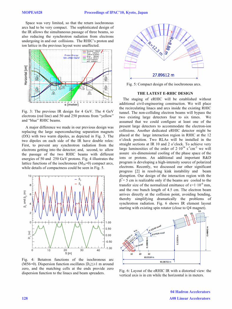
Space was very limited, so that the return isochronous arcs had to be very compact. The sophisticated design of the IR allows the simultaneous passage of three beams, so also reducing the synchrotron radiation from electrons undergoing in and out collisions. The RHIC’s proton and ion lattice in the previous layout were unaffected.
Fig. 3: The previous IR design for 4 GeV. The 4 GeV electrons (red line) and 50 and 250 protons from “yellow” and “blue” RHIC beams.
A major difference we made in our previous design was replacing the large superconducting separation magnets (DX) with two warm dipoles, as depicted in Fig. 3. The two dipoles on each side of the IR have double roles: First, to prevent any synchrotron radiation from the electrons getting into the detector; and, second, to allow the passage of the two RHIC beams with different energies of 50 and 250 GeV protons. Fig. 4 illustrates the lattice functions of the isochronous (M56=0) compact arcs, while details of compactness could be seen in Fig. 5.
Fig. 4: Betatron functions of the isochronous arc (M56=0). Dispersion function oscillates |Dx|≤±1 m around zero, and the matching cells at the ends provide zero dispersion function to the linacs and beam spreaders.
Fig. 5: Compact design of the isochronous arcs.
THE LATEST E-RHIC DESIGN The staging of eRHIC will be established without
additional civil-engineering construction. We will place the recirculating linacs and arcs inside the existing RHIC tunnel. The non-colliding electron beams will bypass the two existing large detectors four to six times. We assumed that we could configure at least one of the present large detectors to accommodate the electron-ion collisions. Another dedicated eRHIC detector might be placed at the large interaction region in RHIC at the 12 o’clock position. Two RLAs will be installed in the straight sections at IR 10 and 2 o’clock. To achieve very large luminosities of the order of 2·1034 s-1cm-2 we will assure six-dimensional cooling of the phase space of the ions or protons. An additional and important R&D program is developing a high-intensity source of polarized electrons. Recently, we discussed our other significant progress [2] in resolving kink instability and beam disruption. Our design of the interaction region with the β*= 5 cm is realizable only if the beams are cooled to the transfer size of the normalized emittance of ε=1·10-6 mm, and the rms bunch length of 4.5 cm. The electron beam arrives directly at the collision point, avoiding bending, thereby simplifying dramatically the problems of synchrotron radiation. Fig. 6 shows IR element layout starting with existing spin rotator (close to Q4 magnet).
Fig. 6: Layout of the eRHIC IR with a distorted view: the vertical axis is in cm while the horizontal is in meters.
MOPEA028 Proceedings of IPAC’10, Kyoto, Japan
128
04 Hadron Accelerators
A08 Linear Accelerators
The proton- and ion-beams arrive with a crossing angle of 10-mrad with a crab cavity in RHIC. We matched the betatron functions and geometrical constraints to the rest of the existing RHIC lattice (Fig. 7). The local chromatic correction uses the dispersion in the triplets [2,3].
Fig. 7: Betatron functions of the eRHIC with β*=5 cm. The gradients of the Q1 (l=0.85 m), Q2 (l=1.6 m) and Q3 (l=1 m) triplet quadrupoles are ~200 T/m.
Fig. 8 shows the geometrical layout of the elements wherein the vertical axis is in cm, while the horizontal axis is in meters.
Fig. 8: The proton-ion triplet layout with the opening angle of ± 5 mrad. In Fig. 9, we show our preliminary design of the first triplet quadrupole with the electron beam passing through the free magnetic field region
Fig. 9: Preliminary design of the first quadrupole for eRHIC interaction region.
The natural chromaticity of the overall RHIC lattice with the new eRHIC-IR is even smaller than the present one used during the 2010 Au-Au run with 100 GeV/u and with β*~0.7 m. The design of the arc lattice follows the previous momentum-compaction adjustable lattice [5]. Experiments demonstrated its ability to detect deviations within ±5 mrad.
In Fig. 10 we show the 4 m long warm magnet is required due to the geometrical constraints but it to be possibly used for the fragmentation measurements.
Fig. 10: Triplet magnets together with the 4 m long warm dipole could be used for fragmentation measurements.
SUMMARY We are exploring a new “QCD factory” eRHIC project
as a possible continuation of the existing, very successful and exciting nuclear-physics program at RHIC, i.e., a new electron ion collider. We describe the design of the ERL lattice with a β*=5 cm at the collision point. With a transverse emittance of ε=1·10-6 mm mrad and the longitudinal rms size of 4.5 cm, we consider that a luminosity of 2·1034 s-1cm-2 will be achieved. Present layout represents the most cost effective design as it utilizes existing RHIC tunnel avoiding additional civil engineering construction work.
REFERENCES [1] P. Wanderer, IEEE Appl. Superconductivity 19(3)
(2009) 1208. [2] Y. Hao, V. Litvinenko, and V. Ptitsyn, PAC09,
Vancouver, BC, Canada, May 4-8 (2009) WE6PFP057.
[3] P. Raimoni and A. Seryi, Phys. Rev. Lett. 86 (2001)3779.
[4] Y. Alexahin, E. Gianfelice-Wendt, and A. Nepetenko, Muon Collider Design Workshop at BNL, December 1-4, 2009. http://www.cap.bnl.gov/mumu/conf/collider-091201/
[5] D. Trbojevic et al., PAC97, Vancouver, B.C., Canada, 5/12-16/97.