60
Lawrence Chung CS6358.OT1: Module 2 1 Module 2: Introduction to UML
| Date post: | 21-Dec-2015 |
| Category: |
Documents |
| View: | 215 times |
| Download: | 1 times |

Lawrence Chung CS6358.OT1: Module 2 1
Module 2:Introduction to UML

CS6358.OT1: Module 2 2Lawrence Chung
References
Documentation on UML is available from:http://www.rational.com
Rational Rose is available from:http://www.rational.com
Visual Modeling with Rational Rose and UML, Terry Quatrani, 1998.

CS6358.OT1: Module 2 3Lawrence Chung
Overview
Background What is UML for? Building blocks of UML Process for Using UML
CS6358.OT1: Module 2 4Lawrence Chung
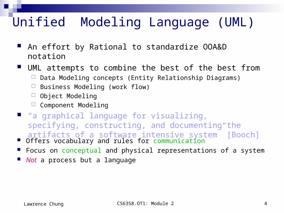
Unified Modeling Language (UML)
An effort by Rational to standardize OOA&D notation UML attempts to combine the best of the best from
Data Modeling concepts (Entity Relationship Diagrams) Business Modeling (work flow) Object Modeling Component Modeling
“a graphical language for visualizing, specifying, constructing, and documenting the artifacts of a software intensive system” [Booch]
Offers vocabulary and rules for communication Focus on conceptual and physical representations of a system Not a process but a language
CS6358.OT1: Module 2 5Lawrence Chung
UML History
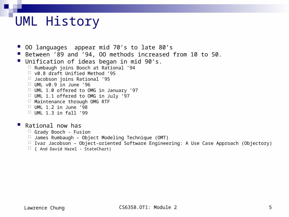
OO languages appear mid 70’s to late 80’s Between ’89 and ’94, OO methods increased from 10 to 50. Unification of ideas began in mid 90’s.
Rumbaugh joins Booch at Rational ’94 v0.8 draft Unified Method ’95 Jacobson joins Rational ’95 UML v0.9 in June ’96 UML 1.0 offered to OMG in January ’97 UML 1.1 offered to OMG in July ’97 Maintenance through OMG RTF UML 1.2 in June ’98 UML 1.3 in fall ’99
Rational now has Grady Booch - Fusion James Rumbaugh – Object Modeling Technique (OMT) Ivar Jacobson – Object-oriented Software Engineering: A Use Case Approach (Objectory) ( And David Harel - StateChart)
CS6358.OT1: Module 2 6Lawrence Chung
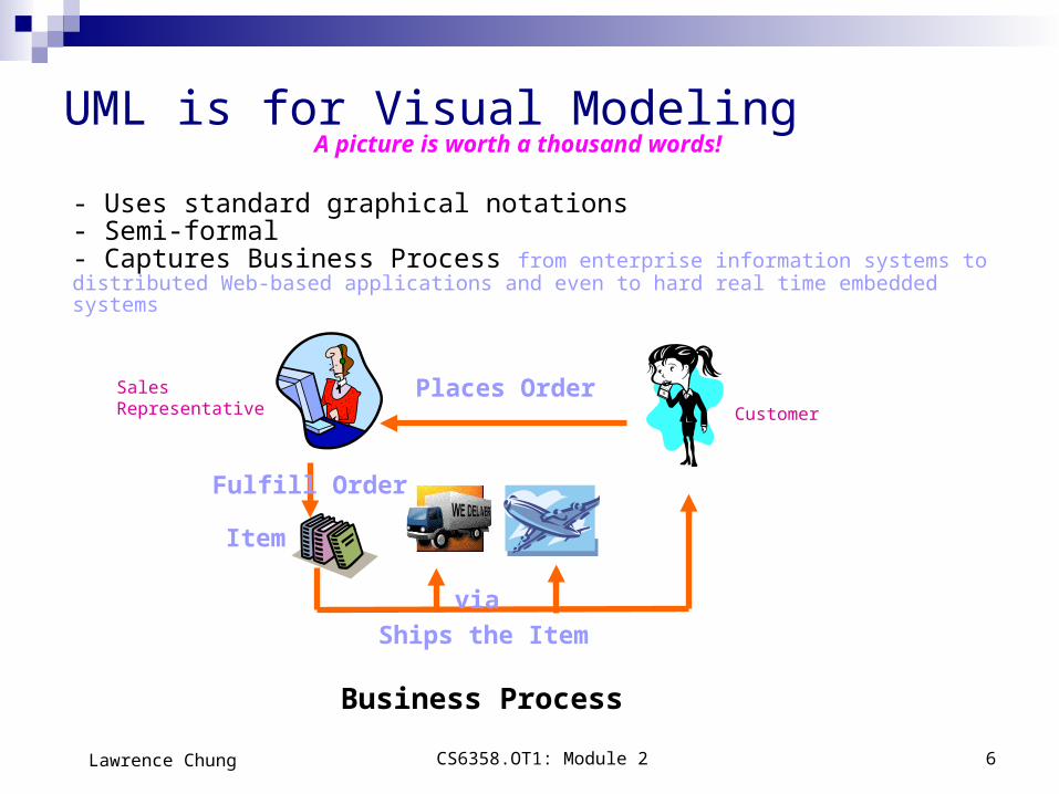
UML is for Visual Modeling
Business Process
Places Order
Item
Ships the Item
- Uses standard graphical notations- Semi-formal- Captures Business Process from enterprise information systems to distributed Web-based applications and even to hard real time embedded systems
A picture is worth a thousand words!
via
Fulfill Order
Customer
Sales Representative

CS6358.OT1: Module 2 7Lawrence Chung
UML is also for …
Specifying building models that are: Precise, Unambiguous, Complete UML symbols are based on well-defined syntax and semantics. UML addresses the specification of all important analysis, design, and
implementation decisions.
Constructing Models are related to OO programming languages. Round-trip engineering requires tool and human intervention to avoid information loss
Forward engineering — direct mapping of a UML model into code. Reverse engineering — reconstruction of a UML model from an implementation.
Documenting Architecture, Requirements, Tests, Activities (Project planning, Release management)
CS6358.OT1: Module 2 8Lawrence Chung
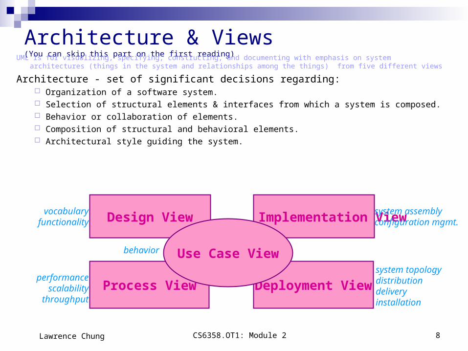
Architecture & Views (You can skip this part on the first reading)
Deployment ViewProcess View
Design View Implementation View
Use Case View
vocabularyfunctionality
performancescalability
throughput
behavior
system assemblyconfiguration mgmt.
system topologydistributiondeliveryinstallation
UML is for visualizing, specifying, constructing, and documenting with emphasis on system architectures (things in the system and relationships among the things) from five different views
Architecture - set of significant decisions regarding: Organization of a software system. Selection of structural elements & interfaces from which a system is composed. Behavior or collaboration of elements. Composition of structural and behavioral elements. Architectural style guiding the system.

CS6358.OT1: Module 2 9Lawrence Chung
Views
Use Case View
Use Case Analysis is a technique to capture business process from user’s perspective. Encompasses the behavior as seen by users, analysts and testers. Specifies forces that shape the architecture. Static aspects captured in use case diagrams. Dynamic aspects captured in interaction diagrams, statechart diagrams, and activity
diagrams.
Design View Encompasses classes, interfaces, and collaborations that define the vocabulary of a
system. Supports functional requirements of the system. Static aspects captured in class diagrams and object diagrams. Dynamic aspects captured in interaction, statechart, and activity diagrams.

CS6358.OT1: Module 2 10Lawrence Chung
Views
Process View Encompasses the threads and processes defining concurrency and synchronization. Addresses performance, scalability, and throughput. Static and dynamic aspects captured as in design view; emphasis on active classes.
Implementation View Encompasses components and files used to assemble and release a physical system. Addresses configuration management. Static aspects captured in component diagrams. Dynamic aspects captured in interaction, statechart, & activity diagrams.
Deployment View Encompasses the nodes that form the system hardware topology. Addresses distribution, delivery, and installation. Static aspects captured in deployment diagrams. Dynamic aspects captured in interaction, statechart, & activity diagrams.

CS6358.OT1: Module 2 11Lawrence Chung
Three (3) basic building blocks of UML
Things
important modeling concepts (individual ones as the primitive kinds)
Relationships
tying individual things (i.e., their concepts)
Diagrams
grouping interrelated collections of things and relationships

CS6358.OT1: Module 2 12Lawrence Chung
Structural — nouns of UML models. Behavioral — dynamic (verbal) parts of UML
models. Grouping — organizational parts of UML models. Annotational — explanatory parts of UML models.
3 basic building blocks of UML - Things
CS6358.OT1: Module 2 13Lawrence Chung
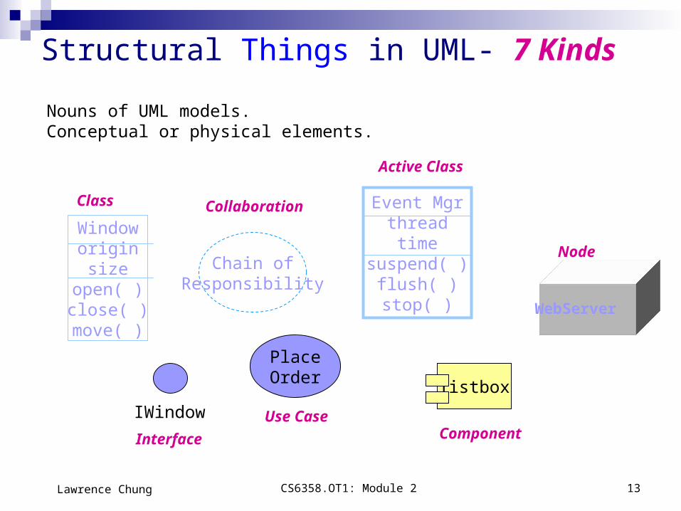
Nouns of UML models.Conceptual or physical elements.
Structural Things in UML- 7 Kinds
Windoworiginsize
open( )close( )move( )
IWindow
Chain ofResponsibility
PlaceOrder
Event Mgrthreadtime
suspend( )flush( )stop( )
listbox
Class
Interface
Collaboration
Use Case
Active Class
Component
Node
WebServer

CS6358.OT1: Module 2 14Lawrence Chung
1. ClassA description of a set of objects that share the same attributes, operations, relationships, and semantics.Usually implements one or more interfaces. Cf. Active Class
Windoworiginsize
open()close()
name
attributes
operations
Structural Things in UML
2. InterfaceA collection of operations that specify a service (for a
resource or an action) of a class or component. It describes the externally visible behavior of that element.
<<interface>>IWindow
open()close()
name
operations
IWindow

CS6358.OT1: Module 2 15Lawrence Chung
Chain ofResponsibility
Define an interaction among a web of objects.Define a society of roles and other elements.Provide cooperative behavior.Capture structural and behavioral dimensions.
3. Collaboration
Structural Things in UML
Place OrderA sequence of actions that produce an observable result for a specific actor.Provides a structure for behavioral things.Realized through a collaboration (usually realized by a set of actors and the system to be built).
4. Use Case

CS6358.OT1: Module 2 16Lawrence Chung
Special class whose objects own one or more processes or threads.
Can initiate control activity.
Event Manager
suspend()flush()
nameattributes
operations
Heavy border
5. Active Class
Structural Things in UML
Threadtime
Orderform.javaReplaceable part of a system.Components can be packaged logically.Conforms to a set of interfaces.Provides the realization of an interface.
6. Component
WebServerElement that exists at run time.Represents a computational resource.Generally has memory and processing power.
7. Node
Variations on Structural Things: Actors, Signals, Utilities, Processes & Threads, Applications, Documents, etc.

CS6358.OT1: Module 2 17Lawrence Chung
Behavioral Things in UML
Two primary kinds of behavioral things:
Verbs of UML models.Dynamic parts of UML models: “behavior over time and space”Usually connected to structural things in UML.
Interactionbehavior of a set of objects comprising of a set of message exchanges within a particular context to accomplish a specific purpose.
display
State Machinebehavior that specifies the sequences of states an object or an interaction goes through during its lifetime in response to events, together with its responses to those events.
WaitingIdle

CS6358.OT1: Module 2 18Lawrence Chung
Packages - one primary kind of grouping. - General purpose mechanism for organizing elements into groups.
- Purely conceptual; only exists at development time.- Contains behavioral and structural things.- Can be nested.- Variations of packages are: Frameworks, models, & subsystems.
Meeting Scheduler
Grouping Things in UML

CS6358.OT1: Module 2 19Lawrence Chung
Annotational Things in UML
flexible drop-out dates
Explanatory parts of UML modelsComments regarding other UML elements (usually called adornments in UML)
Note is one primary annotational thing in UMLbest expressed in informal or formal text.

CS6358.OT1: Module 2 20Lawrence Chung
3 basic building blocks of UML - Relationships
4 Kinds
Dependency Association Generalization Realization

CS6358.OT1: Module 2 21Lawrence Chung
2. Associationsa structural relationship that describes a set of links, a link being a connection between objects.
Can be directed labels Can have multiplicity & role names
1. Dependencya semantic relationship between two things in which a change to one thing (independent) may affect the semantics of the other thing (dependent).
Relationships in UML
Directed is optional and label is optional.
0..1employer
*
employee
Aggregation a special kind of association. It represents a structural relationship between the whole and its parts. Represented by a black diamond.

CS6358.OT1: Module 2 22Lawrence Chung
Relationships in UML
3. Generalizationa specialization/generalization relationship in which objects of the specialized element (the child) are more specific than the objects of the generalized element.
4. Realizationa semantic relationship between two elements, wherein one element guarantees to carry out what is expected by the other element.
Where?Between interfaces and classes that realize them…Between use cases and the collaborations that realize them...
CS6358.OT1: Module 2 23Lawrence Chung
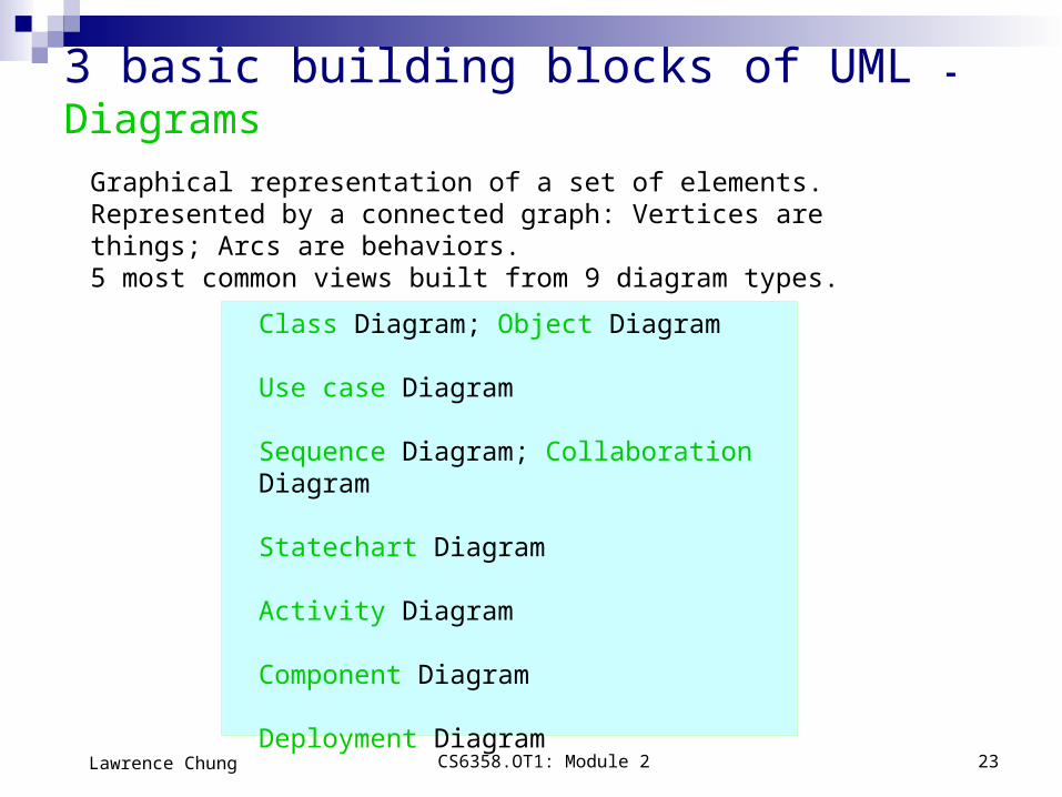
3 basic building blocks of UML - Diagrams
Class Diagram; Object Diagram
Use case Diagram
Sequence Diagram; Collaboration Diagram
Statechart Diagram
Activity Diagram
Component Diagram
Deployment Diagram
Graphical representation of a set of elements.Represented by a connected graph: Vertices are things; Arcs are behaviors.5 most common views built from 9 diagram types.
CS6358.OT1: Module 2 24Lawrence Chung
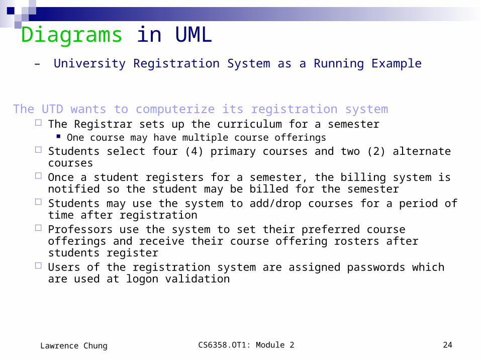
Diagrams in UML – University Registration System as a Running Example
The UTD wants to computerize its registration system The Registrar sets up the curriculum for a semester
One course may have multiple course offerings Students select four (4) primary courses and two (2) alternate courses Once a student registers for a semester, the billing system is notified so the
student may be billed for the semester Students may use the system to add/drop courses for a period of time after
registration Professors use the system to set their preferred course offerings and receive
their course offering rosters after students register Users of the registration system are assigned passwords which are used at
logon validation

CS6358.OT1: Module 2 25Lawrence Chung
Diagrams in UML – Actors in Use Case Diagram
Student
RegistrarProfessor
Billing System
An actor is someone or some thing that must interact with the system under development

CS6358.OT1: Module 2 26Lawrence Chung
Diagrams in UML - Use Cases in Use Case Diagram
Maintain ScheduleMaintain Curriculum Request Course Roster
A use case is a pattern of behavior the system exhibits– Each use case is a sequence of related transactions performed by an actor and the system in a dialogue
Actors are examined to determine their needs– Registrar -- maintain the curriculum
– Professor – set course offerings and request roster
– Student -- maintain schedule
– Billing System -- receive billing information from registration

CS6358.OT1: Module 2 27Lawrence Chung
Diagrams in UML - Documenting Use Cases in Use Case Diagram
A flow of events is described in documents for each use case Written from an actor point of view
Details what the system must provide to the actor when the use case is executed
Typical contents How the use case starts and ends Normal flow of events Alternate flow of events Exceptional flow of events

CS6358.OT1: Module 2 28Lawrence Chung
Diagrams in UML– Flow of Events for Maintaining Curriculum and Setting Course Offerings
This use case begins when the Registrar logs onto the Registration System and enters his/her password.
The system verifies that the password is valid and prompts the Registrar to select the current semester or a future semester.
The Registrar enters the desired semester.
Flow of Events for Setting Course Offerings
The system prompts the professor to select the desired activity: ADD, DELETE, REVIEW, or QUIT.
If the activity selected is ADD: Add a Course subflow is performed. If the activity selected is DELETE: Delete a Course subflow is performed. If the activity selected is REVIEW: Review Curriculum subflow is performed. If the activity selected is QUIT, the use case ends.
(Maintaining Curriculum and Setting Course Offerings are two of the activities in running university registration system)
Flow of Events for Maintaining Curriculum

CS6358.OT1: Module 2 29Lawrence Chung
Diagrams in UML - Use Case Diagram
Use case diagrams are created to visualize the relationships between actors and use cases
Student
Registrar
Professor
Maintain Schedule
Maintain Curriculum
Request Course Roster
Billing System
Set Course Offerings

CS6358.OT1: Module 2 30Lawrence Chung
Diagrams in UML - Uses and Extends Use Case Relationships in Use Case Diagram
A uses relationship shows behavior common to one or more use cases
An extends relationship shows optional behavior
Register for courses
<<uses>>
Logon validation<<uses>>
Maintain curriculum
Register for Distance Learning courses
<<extends>>

CS6358.OT1: Module 2 31Lawrence Chung
Diagrams in UML - Use Case Realizations
Interaction diagrams describe how use cases are realized as interactions among societies of objects, including the messages that may be dispatched among them. They address the dynamic view of the system.
Two types of interaction diagrams Sequence diagrams Collaboration diagrams
A use case diagram presents an outside view of the system.
Then, how about the inside view of the system?

CS6358.OT1: Module 2 32Lawrence Chung
Diagrams in UML - Sequence Diagram
A sequence diagram displays object interactions arranged in a time sequence
: Student registration form
registration manager
math 101
1: fill in info
2: submit
3: add course(Sue, math 01)
4: are you open?5: are you open?
6: add (Sue)7: add (Sue)
math 101 section 1

CS6358.OT1: Module 2 33Lawrence Chung
: Registrar
course form : CourseForm
theManager : CurriculumManageraCourse :
Course
1: set course info2: process
3: add course
4: new course
Diagrams in UML - Collaboration Diagram Displays object interactions organized around objects and their direct
links to one another. Emphasizes the structural organization of objects that send and
receive messages.
CS6358.OT1: Module 2 34Lawrence Chung
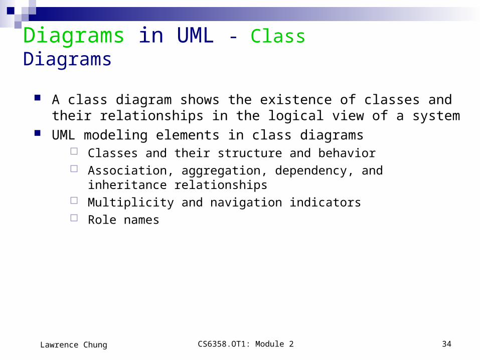
Diagrams in UML - Class Diagrams
A class diagram shows the existence of classes and their relationships in the logical view of a system
UML modeling elements in class diagrams Classes and their structure and behavior Association, aggregation, dependency, and inheritance relationships Multiplicity and navigation indicators Role names

CS6358.OT1: Module 2 35Lawrence Chung
Diagrams in UML - Classes
A class is a collection of objects with common structure, common behavior, common relationships and common semantics
Some classes are shown through the objects in sequence and collaboration diagram
A class is drawn as a rectangle with three compartments Classes should be named using the vocabulary of the domain
Naming standards should be created e.g., all classes are singular nouns starting with a capital letter

CS6358.OT1: Module 2 36Lawrence Chung
Diagrams in UML - Classes: Naming & 3 Sections
RegistrationForm
RegistrationManager
Course
Student
CourseOfferingProfessor
ScheduleAlgorithm
CS6358.OT1: Module 2 37Lawrence Chung
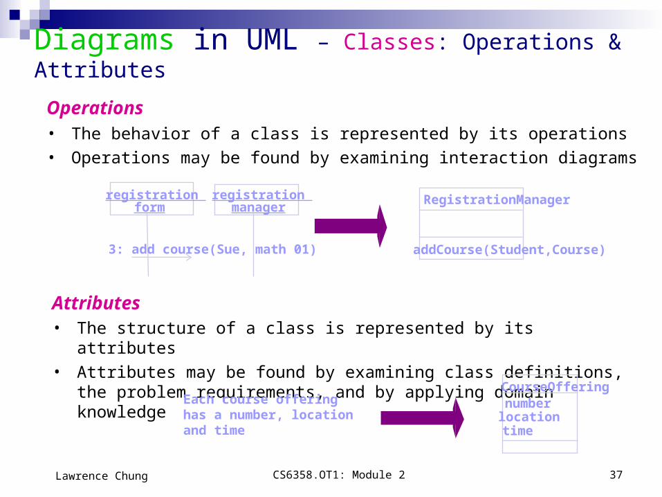
Operations • The behavior of a class is represented by its operations
• Operations may be found by examining interaction diagrams
registration form
registration manager
3: add course(Sue, math 01)
RegistrationManager
addCourse(Student,Course)
Diagrams in UML – Classes: Operations & Attributes
Attributes • The structure of a class is represented by its attributes
• Attributes may be found by examining class definitions, the problem requirements, and by applying domain knowledge
Each course offeringhas a number, location and time
CourseOfferingnumberlocationtime

CS6358.OT1: Module 2 38Lawrence Chung
Diagrams in UML – Some Classes with Operations & Attributes
RegistrationForm
RegistrationManager
addStudent(Course, StudentInfo)Course
namenumberCredits
open()addStudent(StudentInfo)
Studentnamemajor
CourseOfferinglocation
open()addStudent(StudentInfo)
ProfessornametenureStatus
ScheduleAlgorithm

CS6358.OT1: Module 2 39Lawrence Chung
Diagrams in UML – Object Diagrams
• Shows a set of objects and their relationships. • A static snapshot of instances.
Harry (Student)
Name: “Harry Mat”Major: CS
Sue (Professor)
Name: “Sue Becker”tenureStatus: true
CS6358.OT1: Module 2 40Lawrence Chung
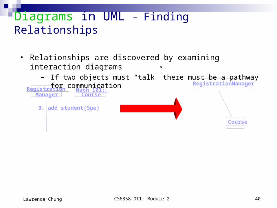
Registration Manager
Math 101: Course
3: add student(Sue)
RegistrationManager
Course
• Relationships are discovered by examining interaction diagrams– If two objects must “talk” there must be a pathway for communication
Diagrams in UML – Finding Relationships
CS6358.OT1: Module 2 41Lawrence Chung
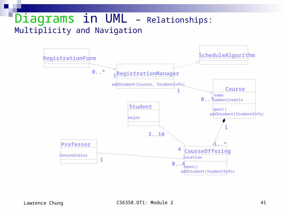
RegistrationForm
RegistrationManager
Course
Student
CourseOfferingProfessor
addStudent(Course, StudentInfo)
namenumberCredits
open()addStudent(StudentInfo)
major
location
open()addStudent(StudentInfo)
tenureStatus
ScheduleAlgorithm
10..*
0..*
1
1
1..*4
3..10
0..41
Diagrams in UML – Relationships: Multiplicity and Navigation
CS6358.OT1: Module 2 42Lawrence Chung
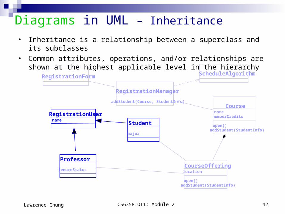
RegistrationForm
RegistrationManager
Course
Student
CourseOfferingProfessor
addStudent(Course, StudentInfo)
namenumberCredits
open()addStudent(StudentInfo)
major
location
open()addStudent(StudentInfo)
tenureStatus
ScheduleAlgorithm
nameRegistrationUser
Diagrams in UML – Inheritance
• Inheritance is a relationship between a superclass and its subclasses
• Common attributes, operations, and/or relationships are shown at the highest applicable level in the hierarchy

CS6358.OT1: Module 2 43Lawrence Chung
InitializationOpen
entry: Register studentexit: Increment count
Closed
Canceled
do: Initialize course
do: Finalize course
do: Notify registered students
Add Student / Set count = 0
Add student[ count < 10 ]
[ count = 10 ]
Cancel
Cancel
Cancel
Diagrams in UML – State Transition Diagram• The life history of a given class• The events that cause a transition from one state to another• The actions that result from a state change

CS6358.OT1: Module 2 44Lawrence Chung
Diagrams in UML – Statechart Diagram
• shows a state machine, consisting of states, transitions, events and activities
Cancelled
Initialization Open
Closed
Add student / Set count = 0
Add student[ Count < 10 ]
Cancel course
Cancel course
[ Count = 10 ] ^CourseReport.Create report

CS6358.OT1: Module 2 45Lawrence Chung
Diagrams in UML – Activity Diagrams• A special kind of statechart diagram that shows the flow from activity to activity.
Not directly supported in Rational Rose 98
BodySwimlanesa mechanism to group and organize activity states
Prepare for speech
Decompress
Synch Mouth Stream Audio
Cleanup
Gesture

CS6358.OT1: Module 2 46Lawrence Chung
Diagrams in UML – Activity Diagrams
Place a state at each synchronization bar!
How do we represent these if not supported by UML, or Rational Rose?
Synchronization
This is the result (Can you figure this out?)
Prepare for speech
Decompress
Synch Mouth Stream Audio
Cleanup
Gesture
Gesture
Prepare for speech
Decompress
Synch Mouth Stream Audio
Cleanup
Sync 1
Sync 2
sync3
Sync 4

CS6358.OT1: Module 2 47Lawrence Chung
Course CourseOffering
Student Professor
Course.dllCourse
People.dllUser
Register.exeBilling.exeBillingSystem
Diagrams in UML – Component Diagram
• shows the organizations and dependencies among a set of components.
Registrar.exe
Courses.dll
People.dll
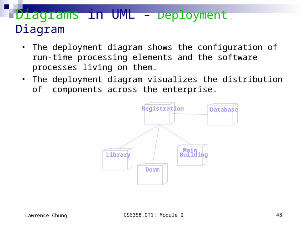
CS6358.OT1: Module 2 48Lawrence Chung
Registration Database
Library
Dorm
Main Building
Diagrams in UML – Deployment Diagram
• The deployment diagram shows the configuration of run-time processing elements and the software processes living on them.
• The deployment diagram visualizes the distribution of components across the enterprise.

CS6358.OT1: Module 2 49Lawrence Chung
• Stereotypes can be used to extend the UML notational elements• Stereotypes may be used to classify and extend associations,
inheritance relationships, classes, and components• Examples:
– Class stereotypes: boundary, control, entity, utility, exception
– Inheritance stereotypes: uses and extends
– Component stereotypes: subsystem
Extensibility of UML
Stereotypes — extends vocabulary.Tagged values — extends properties of UML building blocks.Constraints — extend the semantics of UML building blocks.

CS6358.OT1: Module 2 50Lawrence Chung
Using UML Concepts in a Nutshell
Display the boundary of a system & its major functions using use cases and actors
Illustrate use case realizations with interaction diagrams Represent a static structure of a system using class diagrams Model the behavior of objects with state transition diagrams Reveal the physical implementation architecture with component &
deployment diagrams Extend your functionality with stereotypes

CS6358.OT1: Module 2 51Lawrence Chung
Rules of UML
Well formed models — semantically self-consistent and in harmony with all its related models.
Semantic rules for: Names — what you can call things.
Scope — context that gives meaning to a name.
Visibility — how names can be seen and used. Integrity — how things properly and consistently relate to one another.
Execution — what it means to run or simulate a dynamic model.
Avoid models that are
Elided — certain elements are hidden for simplicity.
Incomplete — certain elements may be missing.
Inconsistent — no guarantee of integrity.

CS6358.OT1: Module 2 52Lawrence Chung
Process for Using UML
How do we use UML as a notation to construct a good model?
Use case driven — use cases are primary artifact for defining behavior of the system.
Architecture-centric — the system’s architecture is primary artifact for conceptualizing, constructing, managing, and evolving the system.
Iterative and incremental — managing streams of executable releases with increasing parts of the architecture included.
The Rational Unified Process (RUP)

CS6358.OT1: Module 2 53Lawrence Chung
• It is planned, managed and predictable …almost• It accommodates changes to requirements with less disruption• It is based on evolving executable prototypes, not documentation• It involves the user/customer throughout the process• It is risk driven
Process for Using UML - Iterative Life Cycle
Primary phases Inception — seed idea is brought up to point of being a viable project. Elaboration — product vision and architecture are defined. Construction — brought from architectural baseline to point of
deployment into user community. Transition — turned over to the user community.

CS6358.OT1: Module 2 54Lawrence Chung
Three Important Features
• Continuous integration - Not done in one lump near the delivery date
• Frequent, executable releases - Some internal; some delivered
• Attack risks through demonstrable progress - Progress measured in products, not documentation or engineering estimates
Process for Using UML - Iterative Approach
Resulting Benefits
• Releases are a forcing function that drives the development team to closure at regular intervals - Cannot have the “90% done with 90% remaining” phenomenon
• Can incorporate problems/issues/changes into future iterations rather than disrupting ongoing production
• The project’s supporting elements (testers, writers, toolsmiths, QA, etc.) can better schedule their work

CS6358.OT1: Module 2 55Lawrence Chung
Initial Project RisksInitial Project Scope
Revise Overall Project Plan• Cost• Schedule• Scope/Content
Plan Iteration N• Cost• Schedule
Assess Iteration N
Risks EliminatedRevise Project Risks• Reprioritize
Develop Iteration N• Collect cost and quality metrics
Define scenarios to address highest risks
Iteration N
Process for Using UML - Risk Reduction Drives Iterations
CS6358.OT1: Module 2 56Lawrence Chung
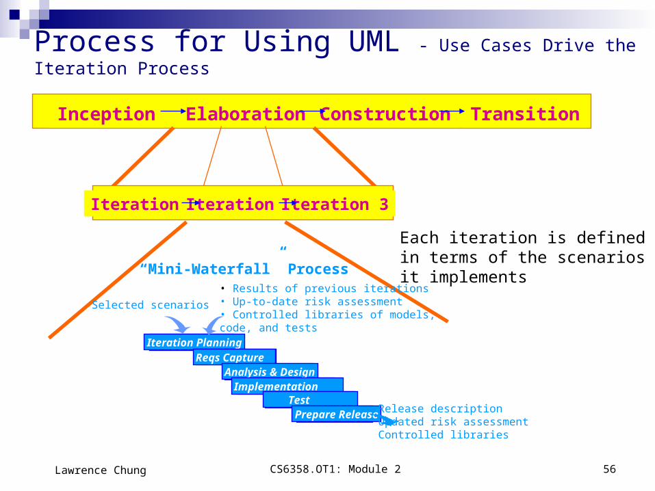
Inception Elaboration Construction Transition
Iteration 1 Iteration 2 Iteration 3
Iteration PlanningReqs Capture
Analysis & DesignImplementation
Test Prepare Release
“Mini-Waterfall” Process
Process for Using UML - Use Cases Drive the Iteration Process
Each iteration is defined in terms of the scenarios it implements
Selected scenarios
• Results of previous iterations• Up-to-date risk assessment• Controlled libraries of models, code, and tests
Release descriptionUpdated risk assessmentControlled libraries

CS6358.OT1: Module 2 57Lawrence Chung
• main reason for using the iterative life cycle:– Not all the needed information up front– Changes throughout the development period
• expect – To face some persistent, recurring risks – To discover new risks along the way– To do some rework; to throw away some lines of code– To change requirements along the way
Process for Using UML - But No Silver Bullet
CS6358.OT1: Module 2 58Lawrence Chung
Summary
Background
What is UML for?
for visualizing, specifying, constructing, and documenting models
Building blocks of UML Things, Relationships (4 kinds) and Diagrams (7 different kinds)
Process for Using UML Use case-driven, Architecture-centric, & Iterative and incremental

CS6358.OT1: Module 2 59Lawrence Chung
Points to Ponder How much unification does UML do? Consider the Object Model Notation on the inside cover on the front and back of the textbook
"Object Oriented Modeling and Design" by Rumbaugh, et.al. 1. List the OMT items that do not exist in UML 2. List the UML items that do not exist in OMT3. For those items of OMT for which UML equivalents exist, map the notation to UML.
Where would you want to use stereotypes? Model the “Business Process” on page 6 in UML. Map the four (4) phases of the RUP to the traditional software lifecycle. If an object refers to a concept, can an object refer to a concept of an
concept? Consider some examples. What would be the essential differences between a property and an
attribute? Consider some examples. What is the syntax and semantics of a class diagram? In Component-Based Software Engineering (CBSE), components are the
units, or building blocks, of a (distributed) software system. What kind of building blocks of UML can be components for CBSE?

CS6358.OT1: Module 2 60Lawrence Chung
Points to Ponder
Are Sequence and Collaboration Diagrams Isomorphic?
: Professor
course options form
course form
course
course offering
5: get professor (professor id)
1: add a course
3: select course offering2: display
4: add professor (professor id)
6: add professor (professor)
: Professorcourse options
formcourse form course course offering
1: add a course
2: display
3: select course offering
4: add professor (professor id)
5: get professor (professor id)
6: add professor (professor)


![BM With the UML Module 2-Using the UML.ppt [Autosaved]](https://static.documents.pub/doc/80x56/577cdd4a1a28ab9e78acb606/bm-with-the-uml-module-2-using-the-umlppt-autosaved.jpg)


