95
Layer-3 Layer-3 forwarding forwarding Yaakov (J) Stein December 2010 Chief Scientist RAD Data Communications
| Date post: | 22-Dec-2015 |
| Category: |
Documents |
| Upload: | mercedes-wynder |
| View: | 223 times |
| Download: | 8 times |
Layer-3Layer-3forwardingforwarding
Yaakov (J) Stein December 2010Chief ScientistRAD Data Communications

Course OutlineCourse Outline
1. Fundamentals of IP
2. The IP header
3. General requirements for routers
4. IP forwarding algorithm walkthrough
5. Search
6. MPLS
7. NAT
Y(J)S L3f 2

Fundamentals of IP

IP networksIP networks
IP networks are made up of hosts middleboxes (e.g., firewalls, NATs, NAPTs, Application Layer GWs) routers (obsolete terminology – gateways)
It will be useful to differentiate between core routers (connect to other routers) edge routers (connect to hosts)
To understand how a router is different from other network elementswe need to know the basic principles the IP protocol architecture
Y(J)S L3f 4

The first principle of IP is the end-to-end (E2E) principleAll functionality should be implemented only with the knowledgeand help of the application at the end points
The second principle is the hourglass model IP (l3) is the common layer below IP (L3) is not part of IP suite, above is
Thus : most functionality and state is in the hosts middlebox functionality is severely limited routers are limited to forwarding packets
without extensive packet manipulation (exception - TTL)
The third principle is that forwarding is connectionless on a hop-by-hop basis
IP
TCP, UDP, …
ftp, http, …
Ethernet, PPP UTP, optic, wireless
The basics (1)The basics (1)
Y(J)S L3f 5
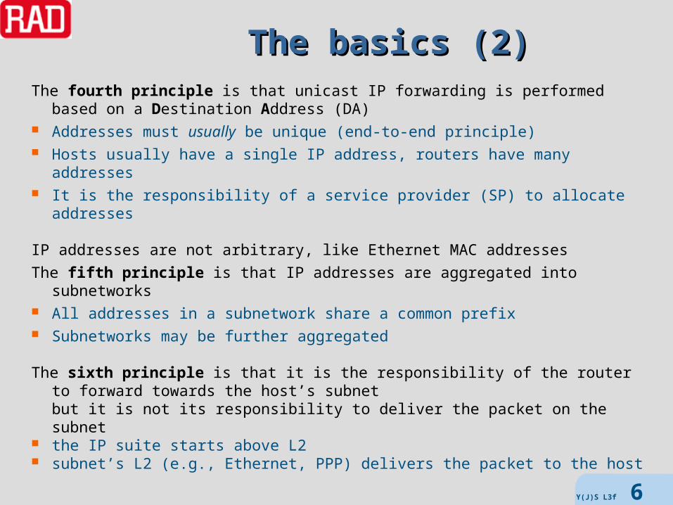
The basics (2)The basics (2)The fourth principle is that unicast IP forwarding is performed
based on a Destination Address (DA) Addresses must usually be unique (end-to-end principle) Hosts usually have a single IP address, routers have many addresses It is the responsibility of a service provider (SP) to allocate addresses
IP addresses are not arbitrary, like Ethernet MAC addresses
The fifth principle is that IP addresses are aggregated into subnetworks All addresses in a subnetwork share a common prefix Subnetworks may be further aggregated
The sixth principle is that it is the responsibility of the router to forward towards the host’s subnet but it is not its responsibility to deliver the packet on the subnet
the IP suite starts above L2 subnet’s L2 (e.g., Ethernet, PPP) delivers the packet to the host
Y(J)S L3f 6

RoutersRouters
A router is a combination of hardware, software, and memorythat is responsible for forwarding packets towards their destinations
Routers generally work at ISO layer 3 (network layer)but can also function at layer “2.5” (for MPLS) and may inspect higher layers, but only for optimization (QoS management, load balancing, etc.)
Note that Ethernet switches technically filter rather than forward
In order to correctly fulfill their function (i.e., to know where to forward)routers usually run routing protocols
to exchange information between themselvesEthernet switches do not need such protocols as they learn how
to filter
So the router performs 2 distinct algorithms : forwarding algorithm (forwarding component) routing algorithm (control component)
switch
router
Y(J)S L3f 7

Router interfacesRouter interfaces
Routers connect to hosts and to other routers via interfaces (from 1 to many thousands of interfaces per router)
Routers are responsible for forwarding packets arriving at an ingress interface to an egress interface
Interfaces have layer 3 and above propertiesand also contain layer a and 2 properties (ports)
Most interfaces have unique IP addresses(but there are also un-numbered interfaces)
Interfaces are grouped into subnetworksAll interfaces on a subnetwork share the same prefix
0.0.0.0/0
192.0.2.128/25
192.0.2.0/25
.1.2
.3
.129
.130
.131
Y(J)S L3f 8

Router forwardingRouter forwarding
Based on the 6 principles we can understand how routers forward
1. The router looks at the packet header2. It deduces to which subnet the packet belongs3. If the router can directly interface that subnet
it must use the appropriate L2 to send the packet to the host
4. Otherwise it must retrieve the next hop (router)that sends the packet towards the subnet
5. The next router does the same6. If routing has converged there will be no loops or black holes
but there may be during transients
The information needed by the router to properly forward packetsis stored in the Forwarding Information Base (FIB)
The FIB associates address prefixes with Next Hops (NHs)(and, to save an additional lookup, usually with L2 addresses as well)
Do not confuse the FIB with a Routing Information Base (RIB) Y(J)S L3f 9

More on FIBsMore on FIBsSimple (and primitive) routers have a routing table
modern large routers have several different databases
The FIB is designed to be fast to searchRIBs are designed to be fast to update
There may be many RIBs, one for each routing protocol runningand static routes may be entered into any of them
There are sometime other databases as wellfor example – link state routing protocols require a LSDB from which the RIB is built
The FIB is built from RIBs
Y(J)S L3f 10
entry prefix interface NH L2 L2 parameters
0 192.168.16.0/24 1 10.10.1.1 PPP …
1 192.168.196.0/20 2 10.16.54.2 Eth …
2 192.168.0.0/17 2 10.16.1.16 Eth …
3 0.0.0.0/0 3 10.1.1.0 Eth …
FIB

IP Routing typesIP Routing types Distance Vector (Bellman-Ford), e.g. RIP, RIPv2, IGRP, EIGRP
– send <addr,cost> to neighbors– routers maintain cost to all destinations– need to solve “count to problem“
Path Vector, e.g. BGP– send <addr,cost,path> to neighbors– similar to distance vector, but w/o “count to problem“– like distance vector has slow convergence*– doesn’t require consistent topology– can support hierarchical topology => exterior protocol (EGP)
Link State, e.g. OSPF, IS-IS– send <neighbor-addr,cost> to all routers– determine entire flat network topology (SPF - Dijkstra’s algorithm)– fast convergence*, guaranteed loopless => interior routing protocol (IGP)
*convergence time is the time taken until all routers work consistently before convergence is complete packets may be misforwarded, and there may be loops
Y(J)S L3f 11

The IP Header

IPv4 headerIPv4 header
Y(J)S L3f 13
VER IHL ToSDSCP ECN Total Length
Identification flags Fragment Offset
TTL Protocol Header Checksum
Source Address (SA)
Destination Address (DA)
Options padding
VER (4b) = 0100IHL (4b) = Internet Header Length in 32 bit words (if no options then IHL=5) ToS (1B) = DSCP(6b) + ECN(2b)Total length (2B) = length of header + payload in bytes (64K)Identification (2B) = ID for fragmentFlags (3b) = reserved bit + DF (don’t fragment) + MF (more fragments)Fragment Offset (13b) = byte number of first byte in fragment (from zero)Header Checksum (16b) = 1s complement sum of header words (0) TTL (1B) = Time To Live counter decremented by each forwarderProtocol (1B) = protocol code (maintained by IANA, 1=ICMP 4=IPv4 6=TCP 17=UDP)
Addresses (4B each)
ToSToS
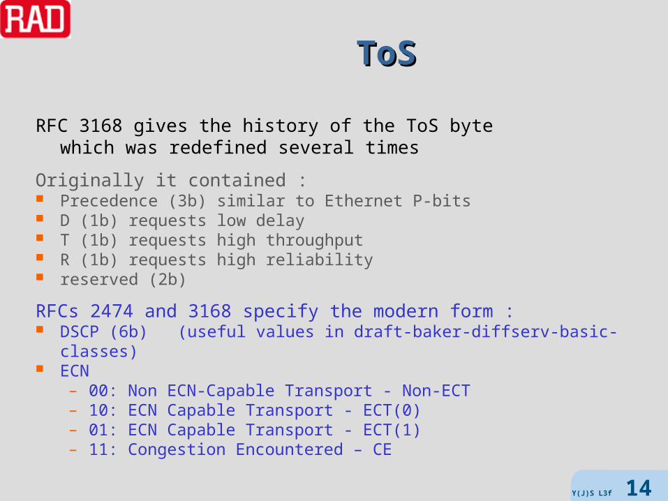
RFC 3168 gives the history of the ToS bytewhich was redefined several times
Originally it contained : Precedence (3b) similar to Ethernet P-bits D (1b) requests low delay T (1b) requests high throughput R (1b) requests high reliability reserved (2b)
RFCs 2474 and 3168 specify the modern form : DSCP (6b) (useful values in draft-baker-diffserv-basic-classes) ECN
– 00: Non ECN-Capable Transport - Non-ECT – 10: ECN Capable Transport - ECT(0) – 01: ECN Capable Transport - ECT(1) – 11: Congestion Encountered – CE
Y(J)S L3f 14

TTLTTL
TTL is used to terminate routing loops limit the lifetime of TCP segments enable traceroute
TTL was originally intended to be the time-in-flight in secondsbut since a router must decrement by at least 1 (even if the time << 1 sec)
each router is required to reduce the TTL field by at least oneso it is effectively a hop-count(today no-one decrements by more than 1 because of time)
TTL expiration causes routers to discard packetsbut TTL=1never triggers a discard for – a destination host – a router receiving a packet destined for it
Y(J)S L3f 15
IP addresses and hierarchyIP addresses and hierarchy
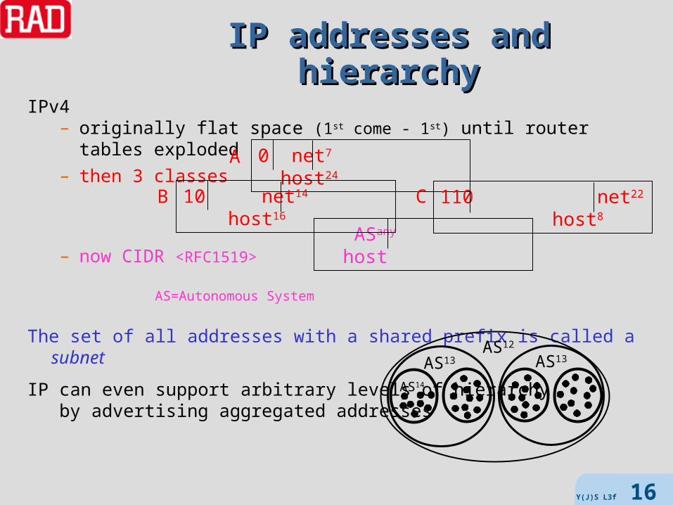
IPv4 – originally flat space (1st come - 1st) until router tables exploded
– then 3 classes
– now CIDR <RFC1519> AS=Autonomous
System
The set of all addresses with a shared prefix is called a subnet
IP can even support arbitrary levels of hierarchyby advertising aggregated addresses
ASany host
0 net7 host24A
10 net14 host16B 110 net22 host8C
AS12
AS13AS13
AS14
Y(J)S L3f 16
FForwarding orwarding EEquivalence quivalence CClasslass
equivalence class - set of elements sharing common characteristicsthat can be considered equivalent for some purpose
Theorem (from set theory) - any equality relation (e.g. common features)divides all entities into non-overlapping equivalence classes
When forwarding, a router needs only to consider destination (and sometimes source) address service requirements (e.g. priority, BW, allowed delay, etc)
we can group together all packets with the samedestination and service requirements as a FEC
by the theorem every packet belongs to one unique FEC
Y(J)S L3f 17
Addresses with lots of onesAddresses with lots of onesRFC 919 defined the IP broadcast address FF.FF.FF.FF (all-ones)
sometimes called all subnets or limited broadcast
RFC 922 extended this to subnet broadcasting prefix+all-onesthis address is called all hosts or directed broadcast
There are several other special IP broadcast addressesthat must be treated in the same was as all-ones
Broadcast must be supported by L2, and are used for purposes such asARP, DHCP, routing advertisements to “all routers”
Broadcast packets are never forwarded by L3 forwarding devices
All-ones must never appear as SAand as DA must be accepted by all routers and hosts
Directed broadcast may appear as SAas DA it must be accepted by hosts
and by default must be accepted by all routersand by default are forwarded (only prefixes count)
but there must be an option not to forward, which must default to forwardmight want to turn off for security reasons!
Y(J)S L3f 18

Addresses with lots of zerosAddresses with lots of zeros
RFC 950 declared prefix+all-zeros to be an illegal addressRFC 1878 repealed this, so prefix+all-zeros is now a legal address
However, all-zeros (0.0.0.0) is not allowedas it stands for this host on this network
A router should never send a packet to 0.0.0.0except as part of its own initialization
A router receiving a packet with source 0.0.0.0 must never forward it
However there are protocols that use this (e.g. DHCP, ICMP mask request) a router must accept such a packet if it knows the protocol
A router receiving a packet with destination 0.0.0.0should silently discard itbut may treat it as a broadcast
Y(J)S L3f 19

Local loopback addressesLocal loopback addresses
Network 127(i.e. all addresses 127.X.X.X = 01111111.X.X.X)
is a network of host internal loopback addresses
Such addresses must never appear on a physical link (outside host)
A host can send a packet to itself using this kind of addressFor example :
a router needing to send a packet through the forwarding engine a 2nd time or to its control plane
can address it to a loopback address
A router should not forward a packet with a loopback source addressexcept over a loopback interface
but it may have a switch that disables this check
Y(J)S L3f 20

Multicast addressesMulticast addresses
RFC 1112 defines IP addresses with MS byte E0- EF(i.e. addresses 224.0.0.0-239.255.255.255)
to be multicast addresses
A multicast address stands for a group of hosts membership is dynamic (hosts may join/leave a group at any time) there is no restriction on the number of hosts in a group a host may belong to many groups
Multicast IP forwarding is performed by a multicast router which may be a regular router too
Addresses between 224.0.0.0 and 224.0.0.255 (inclusive) are reserved for special purposes (e.g., routing protocols)
Multicast routers should not forward packets with such a destination address
We won’t discuss multicast further
Y(J)S L3f 21

Prefixes and masksPrefixes and masks
Since 1993 (RFC 1519 - CIDR) subnets can have any length prefix
There are two ways of specifying the prefix length slash notation, e.g., 192.168.16.0/20
note – unspecified bits are set to zero mask notation, e.g., 192.168.16.0 with mask 255.255.240.0
Note that 192.168.16.0/20 means all addresses from 192.168.16.0 through 192.168.31.255
Note that it contains 192.168.16.0/21, 192.168.24.0/22, etc. since they are in the range and have longer prefixes (larger masks)
/32 are fully qualified IP addresses
0.0.0.0/0 matches every IP address – it is the default route
route taken when there is no matching entry in FIB the gateway of last resort
Y(J)S L3f 22

Prefix tablesPrefix tables
slash MaskA.B.C.D/32 255.255.255.255
A.B.C.D/31 255.255.255.254
A.B.C.D/30 255.255.255.252
A.B.C.D/29 255.255.255.248
A.B.C.D/28 255.255.255.240
A.B.C.D/27 255.255.255.224
A.B.C.D/26 255.255.255.192
A.B.C.D/25 255.255.255.128
A.B.C.0/24 255.255.255.0
A.B.C.0/23 255.255.254.0
A.B.C.0/22 255.255.252.0
A.B.C.0/21 255.255.248.0
A.B.C.0/20 255.255.240.0
A.B.C.0/19 255.255.224.0
A.B.C.0/18 255.255.192.0
A.B.0.0/17 255.255.128.0
slash maskA.B.0.0/16 255.255.0.0
A.B. 0.0/15 255.254.0.0
A.B. 0.0/14 255.252.0.0
A.B. 0.0/13 255.248.0.0
A.B. 0.0/12 255.240.0.0
A.B. 0.0/11 255.224.0.0
A.B. 0.0/10 255.192.0.0
A.B.0.0/9 255.128.0.0
A.0.0.0/8 255.0.0.0
A.0.0.0/7 254. 0.0.0
A.0.0.0/6 252. 0.0.0
A.0.0.0/5 248. 0.0.0
A.0.0.0/4 240. 0.0.0
A.0.0.0/3 224. 0.0.0
A.0.0.0/2 192. 0.0.0
A.0.0.0/1 128. 0.0.0
0.0.0.0/0 0.0.0.0
Note :for /25 D=0 or 128for /26 D= 0, 64, 128, or 192etc. Y(J)S L3f 23

Some special IP addressesSome special IP addresses
Some IP addresses are reserved for special purposesthey are not assigned by IANA and may require special treatment by router
prefix range purpose
0.0.0.0/8 0.0.0.0 – 0.255.255.255 defaults
10.0.0.0/8 10.0.0.0 – 10.255.255.255 private addresses
127.0.0.0/8 127.0.0.0 – 127.255.255.255 loopback addresses
169.254.0.0/16 169.254.0.0 - 169.254.255.255 zeroconf
172.16.0.0/12 172.16.0.0 - 172.31.255.255 private addresses
192.0.2.0/24 192.0.2.0 - 192.0.2.255 Documentation
192.88.99.0/24 192.88.99.0 - 192.88.99.255 IPv6-IPv4 relay
192.168.0.0/16 192.168.0.0 - 192.168.255.255 private addresses
198.18.0.0/15 198.18.0.0 - 198.19.255.255 device benchmark
224.0.0.0/4 224.0.0.0 – 239.255.255.255 multicast
240.0.0.0/4 240.0.0.0 – 255.255.255.255 reservedY(J)S L3f 24
FragmentationFragmentation
All IP hosts/routers must be able to handle 576 byte packets
IP packets can be up to 64K bytes in sizebut L2 may limit the size of packets that can be transported
IPv4 routers must be able to fragment an incoming packetinto a number of forwarded packets(and should minimize the number of fragments)
All hosts must support reassembly (warning – security hole!)and routers must be able to reassemble packets for itself (e.g., routing)
(IPv6 does not use fragmentation, instead the sender host determines MTU)
MTU may be learned from routing protocolsWhen originating a packet
a router should support RFC 1191 path MTU discovery
We won’t discuss fragmentation further
Y(J)S L3f 25

IP OptionsIP Options
Some options require the router to inserts its address into the header(if there is free space)
Unrecognized IP options must be passed unchanged
Routers MUST support Source Route options (but there may be an option to discard such packets) Record Route option Timestamp option
Packets with IP options are often forwarded via “slow path”
Some large routers are rumored to discard any packet with options
We won’t delve too deeply into option processing
Y(J)S L3f 26

General requirements for routers

RoutersRouters
A router is an IP network element with interfaces on at least 2 subnets
Routers were originally gateways (the term is still seen in default GW, Border Gateway Protocol, …)
although now that word is now usually reserved for network elements that interfaces networks of different technologies
Initially there was no separation between forwarding (data plane), and routing (control plane) this was changed by introduction of the concept of a FEC
Routers perform many functions: L2 functions IP forwarding IP routing (control plane) system support (management plane, error logging, etc.)
We normally differentiate between the fast path (simple forwarding) the slow path (control protocol packets and special cases)
Y(J)S L3f 28
Routers – L2 functionsRouters – L2 functions
L2 functionality includes : encapsulating and decapsulating IP packets into L2 CRC checking/generation sending and receiving IP packets (up to MTU) translating IP destination address into L2 address (including ARPs)
We won’t discuss these here
Y(J)S L3f 29
Routers – IP forwardingRouters – IP forwarding
The forwarding plane receives and forwards IP packets parsing (pulling values from appropriate fields – simple IPv4 DA, complex finding URL or MIB variable)
dropping invalid packets lookup/search classifying FECs (add metadata, based on DA, DA+ToS, MPLS, …) modification and replication of packets recognizing error conditions and generating ICMP messages fragments packets when necessary choosing a next-hop destination for each packet
based on information in its Forwarding Information Base (FIB) forwarding packet traffic management and queuing compression, encryption, etc.
We won’t discuss all of these …
Y(J)S L3f 30

Routers – IP routing, etc.Routers – IP routing, etc.
Routers usually support an interior gateway protocol (IGP) and edge routers support an exterior gateway protocol (EGP)
The control plane of a router consists of : run routing protocols identify interface and next hop L2 addresses populate RIBs (if Link State, perform SPFs) scan all RIBs, and produce FIB (entries map FEC to NH)
Routers provide network management and system support facilities,including SW uploading, debugging, status reporting, exception reporting
Routers may support BFD to monitor continuity with other routers
Routers are usually required to have high performance and availability
Y(J)S L3f 31

Error messagesError messages
IP networks are best effort, so there are no guarantees that packets sent will actually be delivered
ICMP (in addition to the well-known ping and traceroute) provides a basic error reporting mechanism :
Destination Unreachable Messages Source Quench Messages Time Exceeded Messages Redirect Messages Parameter Problem Messages
There are no such reports in cases where we will say “silently discard”and when the problematic packet is any of the following :
an ICMP error message a packet that fails the header validation tests (unless specified there) a packet destined to an IP broadcast or IP multicast address a packet sent as a L2 broadcast or multicast a packet with a Martian SA a packet is a non-initial fragment
Y(J)S L3f 32

IP forwarding algorithmwalkthrough

Where is this defined ?Where is this defined ?
The following process is based on IETF standards :
IPv4 is defined in STD-0005, which includes RFC 791 Internet Protocol (IPv4) RFC 792 ICMP RFC 919 Broadcasting Internet Datagrams RFC 922 Broadcasting Internet datagrams in the presence of subnets RFC 950 Internet Standard Subnetting Procedure RFC 1112 Host extensions for IP multicasting
Behavior of IP hosts in RFC 1122
Behavior of routers in RFC 1812
IP forwarding MIB is in RFC 4292
Other details are purposely distributed among many RFCs and elsewhere
We will skip over numerous special cases and rare protocols
We will cover IPv4 only (IPv6 requires another talk)
Y(J)S L3f 34
obsoleted
Layer-2 deliveryLayer-2 deliveryIP packets are always delivered over a lower layer (L2), such as Ethernet PPP PoS GFP over serial GRE MPLS
The L2 is not specified by IP standards, but must provide the following services :
delivery only of packets that passed basic error detectioni.e., discard of faulty packets
delivery only of packets identified as IPv4e.g., by EtherType or UPI
delineation of packetincluding elimination of padding
supplying length of IP packet (we will call this the L2-length)
Y(J)S L3f 35

Initial sanity checksInitial sanity checks
RFC 1812 Section 5.2.2 mandates 5 initial header validation checks checks MUST NOT be disabled, and SHOULD be performed in order
1. L2-length must be 20 B (minimum IP packet size)2. Header Checksum must be correct3. VER = 44. IHL 20 B5. Total Length IHLSHOULD perform the following too6. L2-length Total Length
If any check fails – MUST discard the packet
Note: If pass 2 and 3 then MAY respond with ICMP Parameter Problem message
The router MAY try to determine why the check failed IP header was truncated by lower layer IP header was corrupted not IPv4 (e.g., IPv6) sender purposely generated illegal IP header
Y(J)S L3f 36
Note – no field is used before it is verified
What’s next ?What’s next ?
Now that we are reasonably sure that the packet header is OKwe can look at it
Note that we do NOT check the TTL field yet because packets for the router itself
are not discarded because of TTL expiry
Note that reassembly is not performed(and is only performed by a router for packets destined for itself)
Most of the IP options are processed now (but we won’t go into the details)except those requiring the router’s IP addressthat can only be processed after the forwarding decision
The next step is to observe the address fields
Y(J)S L3f 37

Martian AddressesMartian Addresses
Illegal IP addresses are called Martian addressesbecause they appear as if from outside this world
This includes addresses previously described, for example : 0:0:0:0 as SA or DA 127:X:X:X as SA or DA FF.FF.FF.FF as SA special broadcast addresses multicast addresses as SA
A router should silently discard packets with Martian addresses
There may be a switch to disable this check but it must default to “perform checks”!
When a packet is discarded because of these rules, the details should be logged
Y(J)S L3f 38

Source Address ValidationSource Address Validation
In addition to testing for Martian source addresses, routers should implement source address validation
However, this check is not enabled by default
The check entails looking up the packet’s source address in the FIBand verifying that it is consistent with the logical interface
If enabled, a router must silently discard any packet that arrives on a logical interfaceto which its address would not have been forwarded
This may be an important security provision
Y(J)S L3f 39
ACLsACLs
Access Control Lists offer an additional (basic) security mechanismas well as a method of controlling/limiting traffic
Routers should implement configurable ACLs
When enabled, the router observes source and destination addressesand optionally other fields (e.g., protocol field, L4 ports)
before forwarding packets
Forwarding may be either according to include lists or exclude lists Include list – description of packets to be forwarded Exclude list - description of packets to be blocked
When a packet is blocked based on ACLs the details should be loggedan ICMP unreachable message should be sent (configuration option)
Certain vendors have considerably expanded the ACL functionality
Y(J)S L3f 40

Where does it go ?Where does it go ?
The next step is to look at the DA
There are three possibilities :
1. the packet is destined for the router (local delivery)and should be queued for local delivery (reassembled if needed)and processed according to regular IP host rules (RFC 1122)
2. the packet is not destined for the routerand should be queued for forwarding
3. the packet should be queued for forwardingand a copy must be queued for local delivery
Cases where the packet is destined for the routermust be handled first
Y(J)S L3f 41

Is it for me ?Is it for me ?
The packet is destined only for the router (case 1)if its DA is any of the following :
one of the router’s addresses (exact match) the limited broadcast address (FF.FF.FF.FF) a multicast address that is never forwarded (e.g., 224.0.0.1 or 224.0.0.2) AND
at least 1 logical interface associated with the physical interface on which the packet arrived is a member of the destination multicast
group
When a router receives such a packetit must perform all the functionality of a regular host(including L4 functions and higher)
Y(J)S L3f 42

Is it also for me ?Is it also for me ?
The packet is destined for the router and to be forwarded (case 3) if its DA is any of the following :
a directed broadcast address that addresses at least one of the router’s logical interfaces but does not address any of the logical interfaces associated with the physical interface on which the packet arrived
a multicast address which may be forwarded and at least one of the logical interfaces associated with the physical interface on which the packet arrived is a member of the destination multicast group
Note :A packet is delivered locally if the packet’s DA is a directed broadcast address that addresses at least one of the logical interfaces associated with the physical interface on it arrivedIt is also forwarded unless the link on which the packet arrived uses an encapsulation that does not encapsulate broadcasts differently than unicasts (e.g., by using different Link Layer destination addresses).
Y(J)S L3f 43

CaveatCaveat
Routers generally do not forward packets received as L2 broadcasts
A packet is delivered locally if the packet’s DAis a directed broadcast address that addresses at least one of the logical interfaces associated with the physical interface on it arrivedIt is also forwarded unless the link on which the packet arrived uses an encapsulation that does not encapsulate broadcasts differently than unicasts (e.g., by using different Link Layer destination addresses)
The idea is to deal with a directed broadcast to another networkprefix on the same physical link. If the sender sends the broadcast to the router as a L2 unicast this is OK, since the router sees a unicastdestined for a different network prefix than the sender sent it on.So the router can safely send it as a Link Layer broadcast out the same physical link. But if the router can’t tell whether the packetwas received as a L2 unicast, we must ensure that it plays it safe.
Y(J)S L3f 44

TTLTTL
OK, so the packet needs to be forwarded
the next step is to decrement the TTL
if the router is so slow that the time is longer than 1 secondthe router may decrement by more than 1
if TTL 0 then the packet is discardedif the destination is not a multicast address
the router must return an ICMP Time Exceeded message
a router must not discard an IP unicast or broadcast packet with TTL>0even if it is sure that another router along the path to the destination
will decrement the TTL to zero however, a router may do so for IP multicasts (for efficiency reasons)
Y(J)S L3f 45
ForwardingForwarding
OK, so the packet still needs to be forwarded
Now we have to determine --- to whom ?
This is decided based on the destination address
This decision isn’t so simple :
The destination address is not necessarily already in the DA field
Once the true destination address is knownthe router must still determine
if the destination host is directly connected to itand if so on which interface ?
OR if it needs to pass it through another router,and if so, what is the next router’s address (Next-Hop
address)
Y(J)S L3f 46

Source routingSource routingFinding the true destination address is made more complex
because of source routing
Source routing allows (partial or complete) path specificationrather than relying on the route determined by the routing protocols
Source routing adds determinismand may enable achieving performance goals
Two different IP header options are available : SSRR Strict Source and Record Route LSRR Loose Source and Record Route
Note: LSRR packets are often blocked since they enable spoofing attacks
Source routing places a sequence of IP addresses in the options(intermediate routers, and the ultimate address being the host)
and the next router in the sequence in the DA
The router must use the IP DAnot the address of the ultimate destination (last address in the option)
when determining how to handle a packetY(J)S L3f 47
Forwarding with source routingForwarding with source routing
If the packet has more than one source route optionthen the packet is discarded and an ICMP message is returned
If the packet has a source route option, andthe destination address is one of the router’s addresses, andthe pointer in the Source Route Option does not point past the option
endthen the next IP Destination Address is the address pointed at
If the pointer points past the end of the option the router and error message is generated
This IP destination address is now used as the destination address to be searched
Y(J)S L3f 48

Directly accessible ? Directly accessible ?
OK, now we have the destination address,what do we do with it?
The next step is to determine if the destination host is directly accessible
The first step in the general algorithm is applicable only if the router has interfaces without IP addresses
We will omit this case
The router now looks at each of its interfaceseach of which has an IP address starting with a prefix
For each such prefix compare to the corresponding set of bits in the packet’s DA if they match the packet can be transmitted through the interfaceNote: there can never be >1 match in a properly configured router
If no match is found, then we need to find the Next-Hop router
We omit the case where NHRP is used
Y(J)S L3f 49

Finding the next hopFinding the next hop
OK, we now know that the host is not directly accessibleso we need to send through another router
We need to find for this next-hop router its L2 address on which interface it can be reached how to format the IP packet
All of this information is in the appropriate FIB entries
As was explained in the routing course, the FIB is built using RIBs derived from the routing protocol(s) static routes and default routes metrics policy
Here the question is how to find the right FIB entry
Y(J)S L3f 50

Searching the FIBSearching the FIB
next-hop selection is performed by searching the FIB entriesand selecting the best route (if there is one)
All FIB search algorithms start out with the entire FIB and prune
Hopefully, at the end of the pruning exactly one route remainsif none remains (including no default route)
the destination is unreachable. if many remain, the router may choose
based on administrative preferencein order to optimize metricsarbitrarily to perform load balancing (usually least recently used)
There are several FIB search algorithms, depending on traffic type (unicast, unicast with ToS, IP multicast, …) network configuration router architecture
Y(J)S L3f 51
?

How ToS changes thingsHow ToS changes things
When ToS is supported :router must maintain a ToS (DSCP) value for each route in the FIBif routing protocol does not support ToS
packet’s ToS is set to zero (default)
We will describe the default ToS forwarding algorithm
There are other proposals (similar to Ethernet QoS), such as low delay packets placed at head output queue obey drop precedencebut these are not presently required or widely implemented
When unreachable, the ICMP error codes are different with ToS
Y(J)S L3f 52

ToS forwarding algorithmToS forwarding algorithm
router retrieves all routes to destination if none packet dropped (unreachable) else { one or more routes } router performs exact match on ToS (DSCP) if one match router forwards to it else if > 1
router forwards to destination with lowest metric else
{ no match } router looks for route with ToS=0 (DSCP=0) if found
forward to it else { still no match }
packet dropped (unreachable)
Y(J)S L3f 53

Finishing upFinishing up
OK, now we finally know which FIB entry to use
1. retrieve from the FIB the (logical) interface through which we need to send the packet
2. if the packet has IP options that require the router’s IP address(e.g., Record Route, Timestamp)
we can now process them using the router’s address corresponding to the interface
3. fix the IP checksum (in general we do not have to recalculate – we can fix)(NB TCP checksum is never changed, when using source routing the TCP checksum pseudoheader has the ultimate DA)
4. retrieve the L2 parameters for the interface (e.g., Ethernet MACs and VLANs, GRE parameters, …) and build the L2 frame
5. finally, queue the packet for transmissionY(J)S L3f 54

Search

Lookup and data structuresLookup and data structuresLookup comes in several varieties, such as : Exact match (e.g., MAC addresses, VLANs, IP multicast) Longest Prefix Matching (LPM) (needed for searching FIBs) Range matching (e.g., ports, firewalls)
In order to optimize lookup, we use appropriate data structures
Wirth’s law Programs = algorithms + data structures
We need to perform the following on our data structures : Insert Delete Modify Search
and to check the following metrics : Time complexity for each of the above Size (spatial) efficiency Scalability
Y(J)S L3f 56

LookUp TableLookUp TableThe simplest (and fastest) data structure is the LookUp Table (LUT)
AKA indexed array, Location Addressable Memory (LAM)
The incoming address is used as an index to access the (NH) information
We can put in more info, e.g., L2 type and address, to save further lookupsExample :
Limitations only for exact match, not LPM limitation only for small number of possible addresses, e.g. VLANs
We can use LUTs after other data structures that return a key as an index
address interface NH L2 type L2 NH address
0 1 192.0.2.0 Ethernet 00-17-42-F7-14-14
1 2 192.0.2.16 PPP -
2 3 192.0.2.128 SDH VC ID
Y(J)S L3f 57
Hash tablesHash tables
Hash tables enable handling a large number of potential addresses
A hashing function is a function from a large variable (large number of bits or large number of bytes) to a small variable (small number of bits or bytes)which is white (small changes in the input create widely different outputs)
Hashing long addresses returns a short index
The problem is that the hashing function is not 1:1so there will always be the probability of hash clashes (collisions)
Solutions : perfect hashing – only when addresses are known ahead of time index in table returns list of all addresses stored multiple hashing – linear probing, quadratic probing
Hashing is very good for exact match (e.g. MAC addresses)but is not suitable for LPM
Y(J)S L3f 58

Hash implementationHash implementationFrom an efficiency point of view
hash tables are between LUTs and search tables (to be discussed next)
To control collisions, we need a relatively large table (birthday paradox !)
Example : 99% probability of collisionwhen 3000 entries are put into a hash table of size 1 million
Using multiple hashingaverage computational load is O(1 + keys/table-size)
A primitive hash function is the modulo hashH(key) = addr mod table-size table-size should be prime – must not be a power of 2 or close
A better hash function is (for appropriate integer m and fraction f)H(key) = Trunc [ m Frac( f addr) ]
The quality of the hashing function depends on fFor Fibonacci hashing : f = 1 / γ
γ is the golden ratio ½ (√5 – 2) ≈ 1.618
23 people – ½ 57 people – 99%
Y(J)S L3f 59
Search table Search table
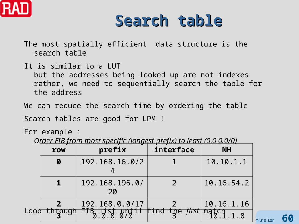
The most spatially efficient data structure is the search table
It is similar to a LUTbut the addresses being looked up are not indexesrather, we need to sequentially search the table for the address
We can reduce the search time by ordering the table
Search tables are good for LPM !
For example :Order FIB from most specific (longest prefix) to least (0.0.0.0/0)
Loop through FIB list until find the first match
row prefix interface NH
0 192.168.16.0/24 1 10.10.1.1
1 192.168.196.0/20 2 10.16.54.2
2 192.168.0.0/17 2 10.16.1.16
3 0.0.0.0/0 3 10.1.1.0
Y(J)S L3f 60
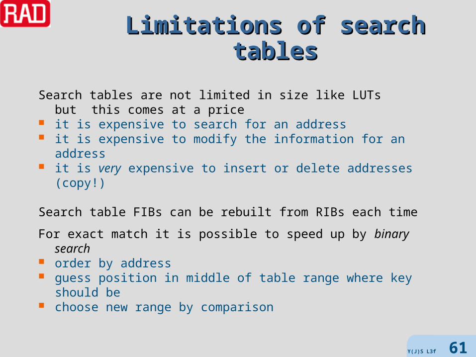
Limitations of search tablesLimitations of search tables
Search tables are not limited in size like LUTsbut this comes at a price
it is expensive to search for an address it is expensive to modify the information for an address it is very expensive to insert or delete addresses (copy!)
Search table FIBs can be rebuilt from RIBs each time
For exact match it is possible to speed up by binary search order by address guess position in middle of table range where key should be choose new range by comparison
Y(J)S L3f 61
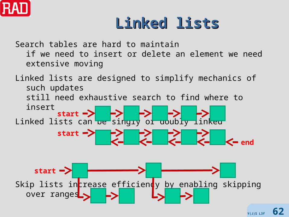
Linked listsLinked listsSearch tables are hard to maintain
if we need to insert or delete an element we need extensive moving
Linked lists are designed to simplify mechanics of such updatesstill need exhaustive search to find where to insert
Linked lists can be singly or doubly linked
Skip lists increase efficiency by enabling skipping over ranges
start
startend
start
Y(J)S L3f 62

Linked list implementationLinked list implementation
If we already know where to insert or what to delete or whom to modifythen linked lists are very efficient
However, search is O(N) where N is the number of entriesworst case Naverage case N / 2
Properly constructed multi-level skip lists take O(log N) on averagebut are still O(N) in the worst case
But if we already need to use double pointersthen trees are better
Y(J)S L3f 63

Tree structuresTree structures
A graph is a collection of nodes and edges connecting themIn a directed graph the edges have direction
and so or every edge there is a father node and a child nodeNodes without children are called leavesA forest is a directed graph without loops (only one path between 2 nodes)A tree is a forest with a single root -- it thus defines a partial order(it is conventional to draw the tree upsidedown)
A binary tree has no more than 2 output edges per node
Trees can be implemented using arrays, pointers (like linked lists), heaps, etc.
forest treebinarytree
Y(J)S L3f 64

Search treesSearch trees
Search trees may store data in their nodes in leaves only on edges combinations of the above
For general search trees searching can be breadth-first or depth-first
Breadth-first start at the root find all children of root and check for desired data if not found, find all children’s children recurse
Depth first start at the root find first child and check for desired data if not found, find first child of first child recurse until data found or leaf if leaf backtrack to father and try the next child
Y(J)S L3f 65

Binary treesBinary treesBinary Search Trees simplify storage and manipulationWe call the children of a node – L and R
Perfect binary trees have exactly 2 children for each internal nodeThus there are exactly 2H leaves, where H is the height of the treeAltogether there are (2H+1 – 1) nodes
To store keys in a binary search tree place keys in all nodes for every intermediate node N
– key(L) < key(N)– key(R) > key(N)
To search for a key in a BST start at root (set current node to root) check if key is stored in current node if not : if key < key(N) then set current to L else set current to R
In the worst case this takes only H comparisons (for perfect trees O(log N))
N
RL
Y(J)S L3f 66

Balanced binary treesBalanced binary trees
Since the search complexity is proportional to the BST’s height Hwe would like to use BSTs with minimal height
Balanced BSTs are not perfect BSTs, but as close as possible to perfectIt is more complex to build a balanced BST, but faster to search
4
2 6
1 3 5 7
2
1
7
3
5
4
6
balancedBST
unbalancedBST
Y(J)S L3f 67

TriesTries
From retrieve, but usually pronounced tryA trie is an ordered tree with subvalues on edges values at leaves
Tries are related to prefix search representations
Tries were originally developed for exact match
Tries can be binary or not
Tries are good for all lexicographical searches O(log n) but particularly efficient for LPM
Trie variants are the fastest known lookups - O(log log n) LC-trie used in modern Linux router implementations
Y(J)S L3f 68

Example trieExample trieAssume the following FIB :10.0.128.0/1610.0.0.0/8192.168.0.0/16192.168.128.0/240.0.0.0/0
Note:in the plain trie, all IP prefixes have the same length
10 1920
0
0
0
/0
0
0 128
0
/16
0
/8
0
168
128
/24/16
0 0
Y(J)S L3f 69
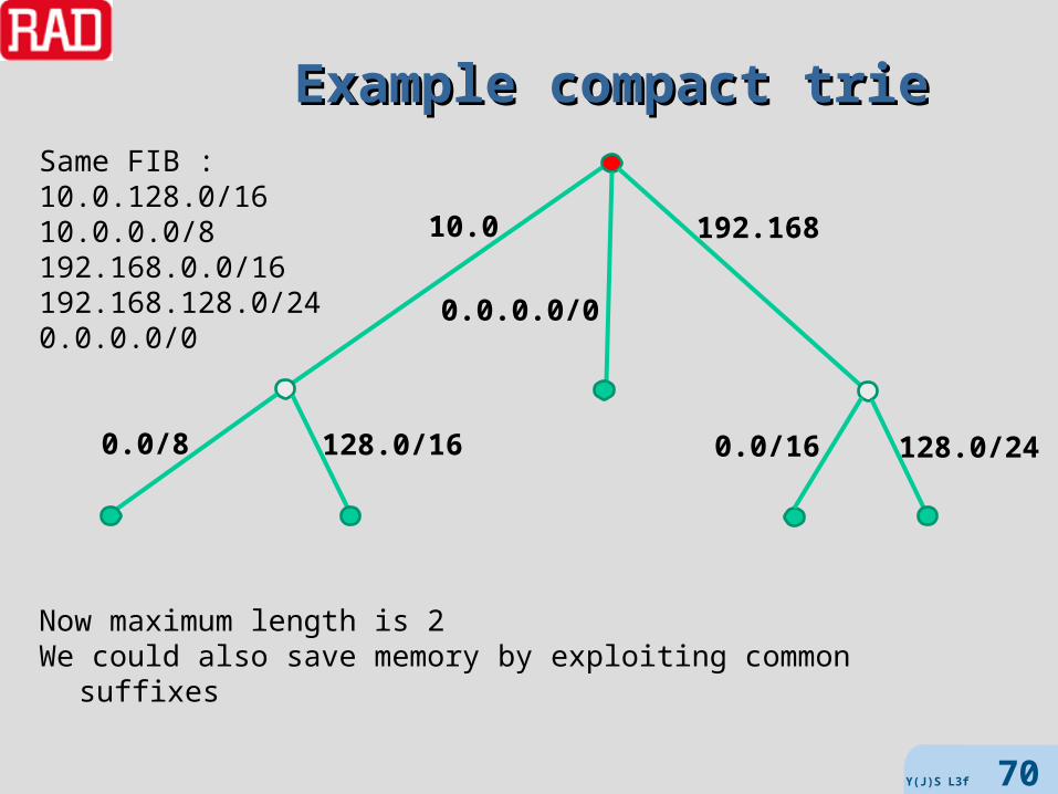
Example compact trieExample compact trieSame FIB :10.0.128.0/1610.0.0.0/8192.168.0.0/16192.168.128.0/240.0.0.0/0
Now maximum length is 2We could also save memory by exploiting common suffixes
10.0 192.168
0.0.0.0/0
128.0/160.0/8 0.0/16 128.0/24
Y(J)S L3f 70

More trie variantsMore trie variants
Patricia triePractical Algorithm to Retrieve Information Coded in Alphanumeric Binary trie which store in nodes the number of bits
to skip before next decision point For LPM store prefixes in internal nodes
Bucket tries Store multiple keys in leaves
Multibit tries (M-tries) Fewer branching decisions than binary tries Multibit strides (usually variable strides)
Level-compressed tries (LC-tries) Replace perfect subtrees in binary trie with single degree 2k nodes LPC trie – level and path compressed
And there are many more (Lulea, full-tree, …)
Y(J)S L3f 71

Example LC-trieExample LC-triebinary trie LC-trie
Y(J)S L3f 72
Content Addressable MemoryContent Addressable Memory
CAM (AKA associative memory)Addressable by content, rather than by location (LAM)Special purpose hardware Fastest possible lookup (essentially searches entire table in one clock) but limited in size usually drives regular memory for additional storage
Binary CAM (BCAM) stores 0 or 1 in each bitTernary CAM (TCAM) allows wildcards Can be used for LPM Can prioritize solution by
– number of bits matched– order in table
CAM technology today 32 to 144 bit keys 128K – 512 K memories hundreds of millions searches per second
Y(J)S L3f 73

Example – 3 bit BCAMExample – 3 bit BCAM
M1[1]
Q[1] Q[2] Q[3]
M2[1]
M3[1]
M1[2] M1[3]
M2[2] M2[3]
M3[2] M3[3]
search lines
match lines
search word
encoder
encode outputto access LAM
Y(J)S L3f 74

Other uses of lookupOther uses of lookup
Deep Packet Inspection URL lookup (often partial or with wildcards)
– can use Trees and tries XML information, patterns, etc. multiple encapsulations
– e.g. Ethernet in IP, MPLS over IP, etc.– there are special-purpose languages to describe such cases
Firewalls, Access Control source/destination IP addresses + source/destination ports 4-tuples TCP/UDP ports in ranges
Y(J)S L3f 75

MPLS

Label Switched ForwardingLabel Switched ForwardingLSP needs to be setup before data is forwarded
and torn down once no longer neededLSR performs
– label switched forwarding* for labeled packets
label space may be– per platform (unique to LSR) or – per port (unique to input interface - like ATM)
LSRs optionally support L3 forwarding for unlabeled packetsingress LER
– assigns packet* to FEC– labels packet– forwards it downstream using label switching
egress LER – removes label– forwards packet using L3 forwarding– exception: PHP (discussed later)
*once packet is assigned to a FEC and labeled, no other LSR looks at the L3 headers/address
Y(J)S L3f 77
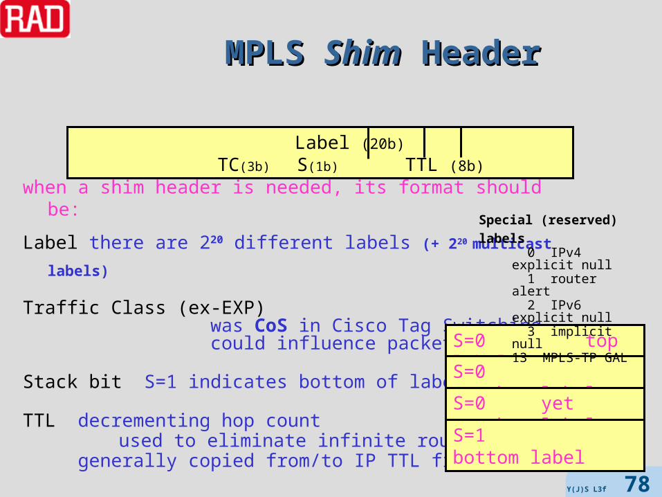
MPLS MPLS ShimShim Header Header
when a shim header is needed, its format should be:
Label there are 220 different labels (+ 220 multicast labels)
Traffic Class (ex-EXP) was CoS in Cisco Tag Switching could influence packet queuing
Stack bit S=1 indicates bottom of label stack
TTL decrementing hop count used to eliminate infinite routing loops
generally copied from/to IP TTL field
Label (20b) TC(3b) S(1b) TTL (8b)
S=0 top label
S=0 another label
S=0 yet another label
S=1 bottom label
Special (reserved) labels 0 IPv4 explicit null 1 router alert 2 IPv6 explicit null 3 implicit null13 MPLS-TP GAL
Y(J)S L3f 78

Y(J)S L3f 79
Single Forwarding AlgorithmSingle Forwarding Algorithm
IP uses different forwarding algorithms for unicast, unicast w/ ToS, multicast, etc.
LSR uses one forwarding algorithm (LER is more complicated)– read top label L– consult Incoming Label Map (forwarding table) [Cisco terminology LFIB]– perform label stack operation (pop L, swap L - M, swap L - M and push N)– forward based on L’s Next Hop Label Forwarding Entry
NHLFE contains:– next hop (output port, IP address of next LSR)
if next hop is the LSR itself then operation must be pop for multicast there may be multiple next hops, and packet is replicated
– label stack operation to be performed– any other info needed to forward (e.g. L2 format, how label is encoded)
ILM contains:– a NHLFE for each incoming label– possibly multiple NHLFEs for a label, but only one used per packet

Y(J)S L3f 80
LER Forwarding AlgorithmLER Forwarding Algorithm
LER’s forwarding algorithm is more complex check if packet is labeled or not if labeled
– then forward as LSR– else
lookup destination IP address in FEC-To-NHLFE Map if in FTN
– then prepend label and forward using LSR algorithm
– else forward using IP forwarding
[Cisco terminology LIB]
LER LSRIProuter
pure IP link MPLS link

All the TablesAll the Tables
FEC table
Free Labels 128-200 presently free
FTN
ILMNHLFE
FEC protocol input port handling
192.115/16 IPv4 2 best-effort
FEC port/label in port/label out
192.115/16 2/17 3/137
port/label in port/label out next hop operation
2/17 3/137 5.4.3.2 swap
Y(J)S L3f 81

LER ArchitectureLER Architecturecontrol plane
user (data) plane
IP routing protocolsIP routing table label binding and
distribution protocols
IP forwarding
tableMPLS
forwarding table
IP routers
labeling procedure
LSRsfree label table
egress LER
FTN
Y(J)S L3f 82

NAT

What is a NAT ?What is a NAT ?
Network Address Translation is the mapping of addresses as known in a network or to an end-user intoaddresses applicable to another network or end-user
NAT functionality is located at a higher layer than IP (L4 and L7)but is often co-located with router functionalityNAT functionality needs to surround the router
When we speak of addresses herewe mean socket addresses = L3 IP address + L4 port number
For IP applications NAT is used for many reasons, including : mapping private addresses into public ones conserving public addresses load balancing blocking malicious traffic tunneling IPv6 over IPv4
Y(J)S L3f 84

Why not static NAT ?Why not static NAT ?
A static NAT (as opposed to a dynamic one) is a NAT where the mapping of certain internal sockets is preconfigured
(IA:IP → EA:EP )or certain ports are opened for internal traffic
(any-address:IP → any-address:EP )and perhaps certain ports are opened for external traffic
A static NAT does not learn or forget
Static NAT may be useful for private networks (where the end-user configures the NAT) or highly constrained applications (networks with fixed number of hosts and only a few traffic types)
but is worse than useless (harmful) for general network use
This is because ports need to be manually opened for traffic and once opened they will probably be forgotten and not closed
It is then relatively easy for outsiders to discover such open ports and penetrate the network
Y(J)S L3f 85

Other Limited NATsOther Limited NATs
It used to be common to speak of various limited NATs basic NAT vs. PAT or NAPT
only IP addresses are mapped, not port numbers DNAT (Destination NAT)
changes DA of outgoing packet and reverse for incomingused for publishing a service on a public IP address
SNAT (Source NAT)opposite of DNAT
SNAT (Softwires NAT)tunnels IPv4 over IPv6 or IPv6 over IPv4
All NATs we discuss may process both (but only IPv4) socket addresses as well as fields in protocols that do not have ports (e.g., ICMP)
Y(J)S L3f 86

NAT varietiesNAT varieties
Until recently, NATs were classified as follows (RFC 3489) : full cone (1:1)
out A:IP → EA:EP independent of Xin any X → IA:IP
address restricted cone out IA:IP → EA:EP independent of X in XA:XP→ IA:IP only if IA:IP previously sent to XA:anyport
port restricted coneout IA:IP → EA:EP independent of X in XA:XP→ IA:IP only if IA:IP previously sent to XA:XP
symmetric out IA:IP → EA:EP with a different mapping for each Xin XA:XP→ IA:IP only if IA:anyport already sent to XA:anyport
Today, these definitions are considered insufficient ! (e.g., RFC 4787)
Y(J)S L3f 87
S=ID=X S=I →E
D=X
S=ED=X

Learning and agingLearning and aging
Dynamic NATs are configured with certain ports open or closed(like static NAT)
and with a pool of external IP addresses
Mappings are learned based on traffic originating behind the NAT
State is retained in the NAT table for “sessions” (usually < 4K)
When the first packet of a session is received (from a host behind the NAT) sockets are compared with configured rules, if OK IA:IP is assigned EA:EP and the mapping inserted in the NAT table the present packet is corrected (including checksums, etc.) and sent packets (in both directions) belonging to the session
are accepted and corrected when the session terminates (based on TCP FIN or time-out)
the NAT entry is deleted
Y(J)S L3f 88

Where are the addresses ?Where are the addresses ?
So, NAT seems easy ! We just have to read and overwrite some addresses/port values !
Unfortunately, it isn’t that easy
IP addresses and port numbers may appear in other places as well
For example, in protocols such as ICMP error messages DNS, routing protocols, etc. FTP SIP (over TCP or UDP) H.323, Skinny, RTSP Instant Messaging, peer-to-peer
Not only are these in unknown places in the payloadThey can be in different formats (including text)
Such cases require Application Level Gateways (ALGs)
Y(J)S L3f 89

Example: FTP – active modeExample: FTP – active mode
Y(J)S L3f 90
CLIENT SERVERP Q 20 21
PORT CLIENT-IP:Q
OK
DATA and ACKs
SYN
client-side NAT problem
need to swap
P,Q 1024 and random
SYN ACK
ACK
SYN ACK
SYN
ACK
FTP command
Note possibility of FTP bounce attack

Example: FTP – passive modeExample: FTP – passive mode
Y(J)S L3f 91
CLIENT SERVERP Q R 21
OK, SERVER-IP:R
DATA and ACKs
SYN
server-side NAT problem
need to swap
P,Q,R 1024 and random
SYN ACK
ACK
ACK
SYN ACK
FTP command
PASV
SYN
considered safer

Example: SIPExample: SIP
Y(J)S L3f 92
ALICE SIP- PROXY SIP- PROXY BOBINVITE
INVITE
INVITEtrying
trying
ringingringing
ringing
ACK
RTP traffic
BYE
OK
where did that come from ?
????
this is on different ports

Other casesOther cases
ICMP error messages include part of the that triggered the messagethe IP header the first few bytes of the packet payload
The internal IP and L4 headers need to be corrected
Peer-to-peer and Instant Messaging are even harder than VoIPthe peer contacts from the network without any previous control
We won’t discuss the next level of NAT here – hole punching algorithms STUN - Session Traversal Utilities for NAT RFC 5389 TURN - Traversal Using Relay NAT RFC 5766 ICE - Interactive Connectivity Establishment RFC 5245
These allow clients behind the NAT to discover the NAT (and learn some parameters and possibly characterize it)
and rely on a STUN server on the network side of the NAT
Y(J)S L3f 93

NAT functionsNAT functions
Mapping outgoing packets SA IA:IP → EA:EP (possibly dependent on XA)
Blocking incoming packetsif SA XA not known
Mapping incoming packetsDA EA:EP → IA:IP (possibly dependent on XA)
Create new mappingwhen receive outgoing packet from new session
Delete mappingaccording to session termination or aging
ALG
Y(J)S L3f 94

NAT processing NAT processing
outgoing packetsperform L3 forwardinglookup socket(s) in NAT tableif found
block or perform NAT (according to table)else
check rulesif pass
create new sessionelse
block
incoming packetslookup socket(s) in NAT tableif found
block or perform NATperform L3 forwarding
elseblock packet
Y(J)S L3f 95


