Summary: This Advice Note updates and replaces TA 48/86. It gives recommendationsfor the geometric design of grade separated junctions and weaving areas withregard to traffic operation and safety.
THE DEPARTMENT OF THE ENVIRONMENT FOR NORTHERN IRELAND
Volume 6 Section 2Part 2 TA 48/92 Registration of Amendments
ELECTRONIC COPY - NOT FOR USE OUTSIDE THE AGENCY
August 1992 PAPER COPIES OF THIS ELECTRONIC DOCUMENT ARE UNCONTROLLED
REGISTRATION OF AMENDMENTS
Amend Page No Signature & Date of Amend Page No Signature & Date ofNo incorporation of No incorporation of
amendments amendments
Volume 6 Section 2Registration of Amendments Part 2 TA 48/92
ELECTRONIC COPY - NOT FOR USE OUTSIDE THE AGENCY
PAPER COPIES OF THIS ELECTRONIC DOCUMENT ARE UNCONTROLLED August 1992
REGISTRATION OF AMENDMENTS
Amend Page No Signature & Date of Amend Page No Signature & Date ofNo incorporation of No incorporation of
amendments amendments
DESIGN MANUAL FOR ROADS AND BRIDGES
ELECTRONIC COPY - NOT FOR USE OUTSIDE THE AGENCY
August 1992 PAPER COPIES OF THIS ELECTRONIC DOCUMENT ARE UNCONTROLLED
VOLUME 6 ROAD GEOMETRYSECTION 2 JUNCTIONS
PART 2
TA 48/92
LAYOUT OF GRADE SEPARATEDJUNCTIONS
Contents
Chapter
1. Introduction
2. General Principles
3. Flow Standards
4. Geometric Standards
5. Layout Options
6. Cyclists and Pedestrians Facilities
7. References
8. Enquiries
Volume 6 Section 2 Chapter 1Part 2 TA 48/92 Introduction
ELECTRONIC COPY - NOT FOR USE OUTSIDE THE AGENCY
August 1992 PAPER COPIES OF THIS ELECTRONIC DOCUMENT ARE UNCONTROLLED 1/1
1. INTRODUCTION
General
1.1 Standard TD 22 (DMRB 6.2.1) sets out theOverseeing Department's design standards andmethodology for the geometric layout of gradeseparated junctions on trunk roads.
1.2 This Advice Note provides guidance on theprinciples for safety and traffic operation on which theStandard TD 22 (DMRB 6.2.1) is based and is intendedto be read in conjunction with it.
1.3 Guidance on how the process of choosing ajunction type may be structured is given more fully inAdvice Note TA 30 (DMRB 5.1).
1.4 TA 48/86 is hereby superseded.
Scope
1.5 Recommendations are given on the siting ofgrade separated junctions in urban and rural areas,alternative layouts, geometric design and the treatmentfor pedestrians and cyclists. Some aspects of signs androad markings are included for completeness, thoughthe full policy and detailed guidance on these mattersare given in the Traffic Signs Manual and StandardTD 18 (DMRB 9.1).
Implementation
1.6 This Advice Note should be used forthwith onall schemes for the construction and improvement oftrunk roads, including motorways, currently beingprepared, provided that, in the opinion of theOverseeing Department, this would not result insignificant additional expense or delay progress. Design Organisations should confirm its application toparticular schemes with the Overseeing Department.
Volume 6 Section 2 Chapter 2Part 2 TA 48/92 General Principles
2. GENERAL PRINCIPLES
Urban/Rural
2.1 Grade separation design is based on the peahourly flow which varies according to road type (TD 2(DMRB 6.2.1) Para 3.1) and according to whether theroad is motorway or all-purpose (TD 22 (DMRB 6.2.1)Table 3/1). Urban standards for most elements of roadesign are, however, lower than those applicable torural roads, since lower driver expectation accompaniby higher perception offset the increased risks causedby reductions in standards. For grade separatedjunctions on dual carriageways, the presence of kerbsfrequent lack of hardstrips, narrow central reserve witsafety fences, lighting and speed limits all confirm theurban nature of the road. The lower urban standardsshown within the hierarchy of geometric standards,ranging from rural motorways down to urban allpurpose roads, related to Design Speed (TD 22 (DMR6.2.1) Table 4/4 and Table 4/5).
Siting
2.2 The siting of a grade separation can have asignificant effect on both its operational performanceand environmental impact. Therefore, consideration othe major contributing factors such as flow, geometricdesign, environmental effect, land take, maintenance,capital cost, topography and economics should beundertaken at the initial design stage to produce theoptimum design for comparison with other junctiontypes.
Departures
2.3 For rural schemes it should normally bepossible to design options which conform toDepartmental Standards. However, this may not bepossible when considering urban schemes due tophysical site constraints, which would result in veryhigh costs and severe environmental damage ifstandards were to be maintained, and thereforeDepartures from Standards will be more likely. Proposals which might involve Departures should bediscussed at an early stage in design with theOverseeing Department.
Safety
2.4 The main objective of grade separated junctio
ELECTRONIC COPY - NOT
August 1992 PAPER COPIES OF THIS ELECTRO
k2
d
ed
,h
are
B
f
n
design is to provide a junction which is safe for theforecast traffic levels. Research on the frequency andseverity of motorway accidents at grade separatedjunctions has shown them to be comparable to theaccidents occurring on the adjacent links, with nodiscernable clustering occurring in the merge/divergeareas. Other research has illustrated differentrelationships for accidents on motorway weavinglengths less then 3km, and grade separated junctionloops (see Para 4.3). Certain layouts are not generallyrecommended for reasons of reduced safety and shouldbe avoided in design. Examples are:
i. grade separated junctions on singlecarriageways (see TD 9 (DMRB 6.1))
ii. grade separation on dual carriageways withinabout 0.5km of the changeover from singlecarriageway standard, measured from the endof the merge taper to the beginning of the righthand lane hatching (see The Traffic SignsManual Ch 4 Figure 4:28);
iii. offside merges and diverges;
iv. a major/minor junction with right turningmovements on an otherwise grade separatedroute.
Layouts
2.5 Recommended layouts for consideration inorder of traffic level are:
i. Diamond or half-cloverleaf;
ii. dumbbell roundabout;
iii. 2 bridge roundabout;
iv. 3 level roundabout;
v. interchange.
The design of an at grade junction within a gradeseparated junction is subject to the appropriateDepartmental Standards and Advice Notes. Forexample, these are TA 23 (DMRB 6.2) for thedetermination of the size of roundabouts andmajor/minor junctions, TD 16 (DMRB 6.2) and TA 42(DMRB 6.2) the Departmental Standard and Advice
FOR USE OUTSIDE THE AGENCY
NIC DOCUMENT ARE UNCONTROLLED 2/1
Chapter 2 Volume 6 Section 2General Principles Part 2 TA 48/92
,
Note respectively, for the geometric design ofroundabouts, and TA 20 (DMRB 6.2) for the layout ofmajor/minor junctions.
All Purpose Road Alternatives
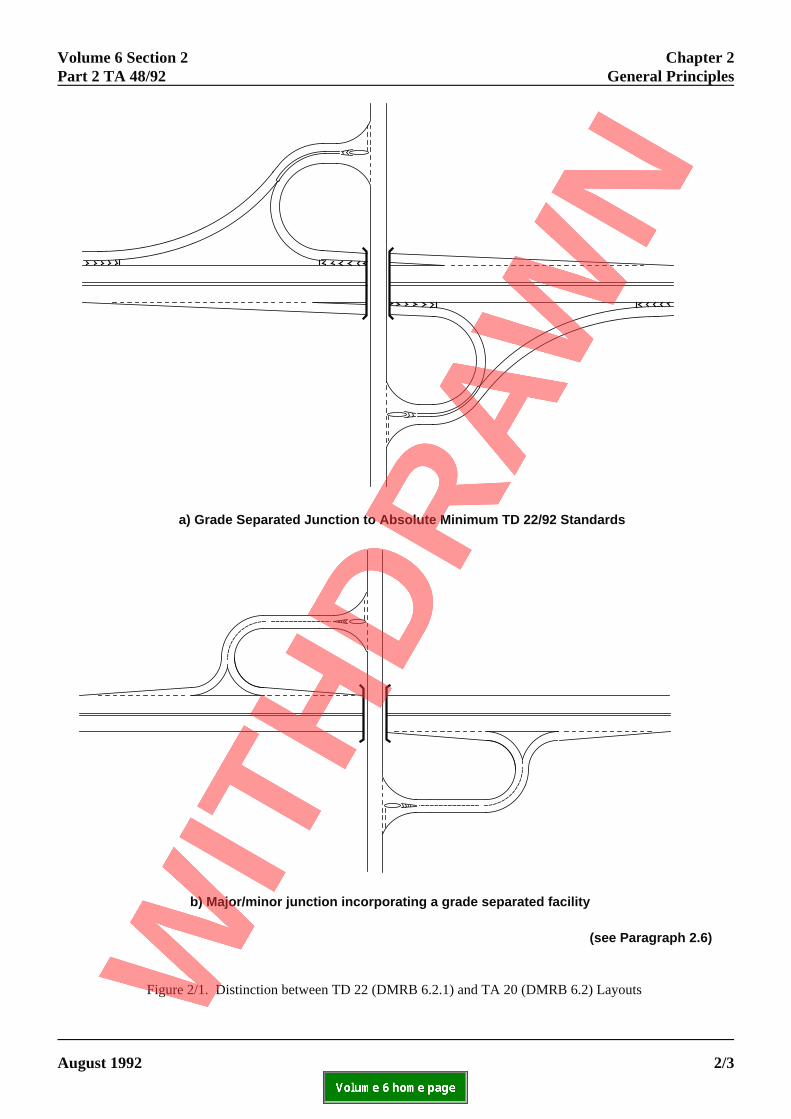
2.6 The geometric standards in TD 22(DMRB 6.2.1) are specifically for grade separatedjunctions which have the appropriate signs and roadmarkings as prescribed in the current edition of theTraffic Signs Regulations and General Directions,upon which advice is given in the Traffic SignsManual. These standards are significantly higher thanthe merge/diverge recommendations given in TA 20/84which should only be used when providing a lowstandard grade separated facility when the signing androad markings reflect the lower standard (see Figure2/1). Using these lower standards, it has been foundthat grade separation can be economically justified atdesign flows of about 20000 AADT on the main line,depending on the turning traffic. This compares with aflow of about 30000 AADT if the geometric standardsin TD 22 (DMRB 6.2.1) are used. These alternativesshould be considered in accordance with TA 30(DMRB 5.1). Grade separation should be pursuedwherever it is economically possible and theenvironmental impact is not significant.
Motorway Service Areas
2.7 The merge/diverge layout design and junctionspacing of a service area, should be based on thegeometric parameters within TD 22 (DMRB 6.2.1).
ELECTRONIC COPY - NOT FOR USE OUTSIDE THE AGENCY
PAPER COPIES OF THIS ELECTRONIC DOCUMENT ARE UNCONTROLLED August 19922/2
Volume 6 Section 2 Chapter 2Part 2 TA 48/92 General Principles
A
(see Paragraph 2.6)
a) Grade Separated Junction to Absolute Minimum TD 22/92 Standards
b) Major/minor junction incorporating a grade separated facility
Figure 2/1. Distinction between TD 22 (DMRB 6.2.1) and TA 20 (DMRB 6.2) Layouts
ELECTRONIC COPY - NOT FOR USE OUTSIDE THE AGENCY
ugust 1992 PAPER COPIES OF THIS ELECTRONIC DOCUMENT ARE UNCONTROLLED 2/3
Chapter 2 Volume 6 Section 2General Principles Part 2 TA 48/92
le
ell
ds
ef
if:
es
Alternative Layouts
General
2.8 Two forms of grade separation are consideregrade separated junctions and interchanges.
Grade Separated Junctions
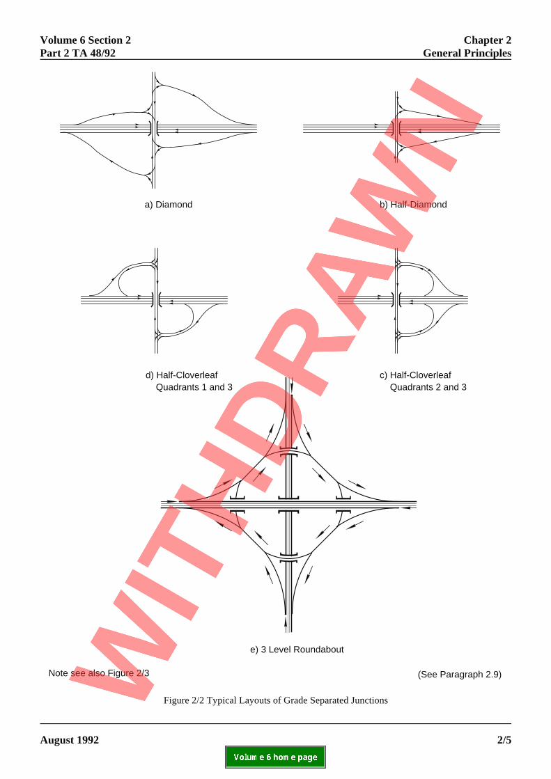
2.9 This form of grade separation involves the usof an at grade junction at the commencement ortermination of slip roads. The at grade junctionelement, whether a major/minor junction or roundaboand slip roads can produce 3 main types of gradeseparation, Diamond, Half-cloverleaf and Roundabouthese are discussed below.
Diamond
2.10 A diamond is the simplest form of gradeseparation, the normal layout will provide turningmovements onto and off the slip roads by two staggejunctions (see Figure 2/2). The use of crossroads is recommended - see TA 20 (DMRB 6.2).
Half-Cloverleaf
2.11 A half-cloverleaf is used at similar flow levelsto a diamond, particularly where site conditions aredifficult and the use of all four quadrants is not possib(see Figure 2/2). The at grade junction elementnormally utilises two ghost islands.
Roundabout
2.12 The two most common forms of gradeseparated roundabout are the two bridge and dumbbtypes - see Fig 2/3 and TA 42 (DMRB 6.2). Thedumbbell type can be adopted to fit either the diamonor half-cloverleaf layout. Where two main routes crosand an interchange is uneconomical or the necessaryland is unavailable, a three level junction utilising aroundabout for turning movements should beconsidered (see Figure 2/2). Some very large twobridge roundabouts have been constructed, but therehave been problems for traffic entering them due to thhigh circulating speeds, though there are examples osuccessful conversions to ring junctions. Large
ELECTRONIC COPY - NOT
PAPER COPIES OF THIS ELECTR2/4
d,
e
ut
t,
rednot
roundabouts are not therefore normally recommendedfor new designs.
2.13 Variants on these three basic types can occur
a. the junction is 3 way ie a T junction:
b. not all movements need catering for ie a halfdiamond:
c. traffic signals, either continuous or part time,are included to remove congestion on anexisting grade separated junction. It isrecommended that they should only normallybe considered as an alternative to priorityjunction design:
d. large flows are to be handled and a signalisedgyratory form of junction is used.
Interchanges
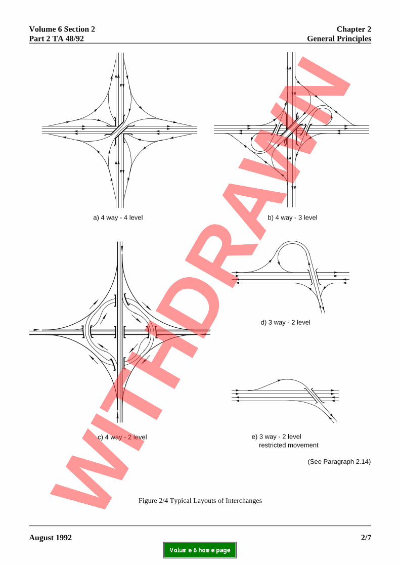
2.14 This form of grade separation does not involvethe use of an at grade junction and thereby providesuninterrupted movement for all turning traffic by theuse of interchange links. Typical layouts are shown inFigure 2/4 for 3 and 4 way interchanges, the advantagand disadvantages are outlined in Chapter 5.
FOR USE OUTSIDE THE AGENCY
ONIC DOCUMENT ARE UNCONTROLLED August 1992
Volume 6 Section 2 Chapter 2Part 2 TA 48/92 General Principles
(See Paragraph 2.9)
a) Diamond b) Half-Diamond
e) 3 Level Roundabout
d) Half-Cloverleaf Quadrants 1 and 3
c) Half-Cloverleaf Quadrants 2 and 3
Note see also Figure 2/3
Figure 2/2 Typical Layouts of Grade Separated Junctions
ELECTRONIC COPY - NOT FOR USE OUTSIDE THE AGENCY
August 1992 PAPER COPIES OF THIS ELECTRONIC DOCUMENT ARE UNCONTROLLED 2/5
Chapter 2 Volume 6 Section 2General Principles Part 2 TA 48/92
2/6
)
Two Bridge Roundabout
One Bridge and Two Roundabouts - "Dumbell"
Figure 2/3 Typical layouts of Grade Separated Junctions - Extract from TA 42 (DMRB 6.2
ELECTRONIC COPY - NOT FOR USE OUTSIDE THE AGENCY
PAPER COPIES OF THIS ELECTRONIC DOCUMENT ARE UNCONTROLLED August 1992
Volume 6 Section 2 Chapter 2Part 2 TA 48/92 General Principles
(See Paragraph 2.14)
a) 4 way - 4 level b) 4 way - 3 level
d) 3 way - 2 level
e) 3 way - 2 level restricted movement
c) 4 way - 2 level
Figure 2/4 Typical Layouts of Interchanges
ELECTRONIC COPY - NOT FOR USE OUTSIDE THE AGENCY
August 1992 PAPER COPIES OF THIS ELECTRONIC DOCUMENT ARE UNCONTROLLED 2/7
Chapter 2 Volume 6 Section 2General Principles Part 2 TA 48/92
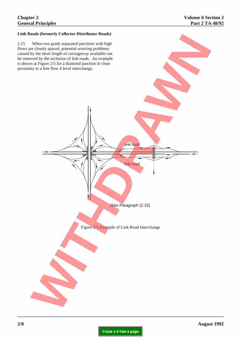
Link Roads (formerly Collector-Distributor Roads)
2.15 When two grade separated junctions with highflows are closely spaced, potential weaving problemscaused by the short length of carriageway available canbe removed by the inclusion of link roads. An exampleis shown at Figure 2/5 for a diamond junction in closeproximity to a free flow 4 level interchange.
2/8
(See Paragraph (2.15)
link road
link road
Figure 2/5 Example of Link Road Interchange
ELECTRONIC COPY - NOT FOR USE OUTSIDE THE AGENCY
PAPER COPIES OF THIS ELECTRONIC DOCUMENT ARE UNCONTROLLED August 1992
3.1 Grade separation design is based on the 30th,50th or 200th highest hourly flow in the 15th year afteropening for urban, inter-urban and recreational roadtypes respectively. These flows have been shown togenerate viable at grade junction options (TA 23DMRB 6.2) and are used in grade separation to produconsistent designs. The hourly flow is normally derivefrom the 24 hour AADT flow, using the peak hourfactors in the Traffic Appraisal Manual for England,Wales and Northern Ireland and the Scottish Trafficand Environmental Appraisal Manual in Scotland. The hourly flows thereby obtained have a high degreeof uncertainty attached to them and should not be useinflexibly in design. The cost of being wrong should beborne in mind and a higher or lower standardconsidered where appropriate. Consideration should bgiven particularly to incorporating a higher standard inurban locations, where development up to the highwayboundary will inevitably take place within a few yearsof the scheme opening, thereby inhibiting any futureimprovement.
Flow Levels
3.2 Maximum hourly flow levels of traffic on themotorway network have increased and this is reflectedin the Standard TD 22 (DMRB 6.2.1.3.2) by convertingflows into lane equivalents. But for the design of theelements of motorway junctions, a maximum figure of1800 vphpl should be used. The figure for All PurposeRoads of 1600 vphpl remains the same. For newdesigns the maximum hourly flows are expected to haan HGV content of less than 10% in the future (15thyear) and any flow correction (TD 22 (DMRB 6.2.1.),Table 3/2) will be minor. However, on improvementschemes the HGV flow correction could be up to 20%,depending on the gradient, representing a severe losslevel of service on that section unless allowed for. Thiemphasises the importance of the correct siting andspacing of junctions at the design stage (para 2.2) if thscheme life of 30 years is to be achieved without theneed for costly interim improvement.
ELECTRONIC COPY - NO
August 1992 PAPER COPIES OF THIS ELECTR
erging and Diverging Lanes
3.3 The typical merging and diverging layoutsillustrated in TD 22 (DMRB 6.2.1) are related to flowlevels by the use of Figures 2/3 and 2/5 therein, usingthe flow levels in para 3.2 above. These figures have
been further developed and refined from those shownce TRRL Report LR 679.d
4.1 For rural interchange links a DesirableMinimum Design Speed Standard of 85 kph isrecommended (TD 22 (DMRB 6.2.1), Table 4/2) asdesigns to lower standards have produced operatioproblems. This has been highlighted by vehiclesshedding their loads at interchanges which involve treverse curves, similar to Fig 2/4c. The 85 kph DesSpeed is in accordance with the speed/flow predicticontained in the appropriate Overseeing Departmencost benefit models (COBA or NESA). However, if thepresence of such a reduced Design Speed elementcannot be made obvious to the driver, a higher valushould be used.
Slip Roads
4.2 Adoption of an 85 kph Design Speed for sliproads would be an unnecessary waste of money anland. Diverging drivers have already made the decito leave the mainline and should be given sufficientvisibility to the at grade junction advance direction sto enable them to reduce their speed accordingly. ADesirable Minimum Design Speed of 70 kph hastherefore been adopted. It should be noted that sliproads in excess of 0.75 km length are defined asinterchange links and accordingly
ELECTRONIC COPY - NO
August 1992 PAPER COPIES OF THIS ELECT
Safety Studies
nal
ightignonts'
e
dsion
ign
have a Design Speed of 85 kph (TD 22 (DMRB 6.2.1),Table 4/2). At difficult sites further relaxations inStopping Sight Distances etc, can be made under theprovisions of TD 9 (DMRB 6.1).
4.3 The research referred to in paragraph 2.4 isdescribed below. It was undertaken to examine theaccident risk of various geometric features.
Safety on Merging and Diverging Lanes
4.4 The accident risk in the merge/diverge area atmotorway grade separated junctions was originallystudied at 53 junctions over the period 1979-81. Threemainline carriageway standards were examined, nameD3M, D2M and D3/2M (with a lane drop), within theflow range 10-85000 24hr AADT. The accident ratesand severities are shown in Table 4/1. The resultsindicated that there was some difference from thenational motorway rate with the D3M behaving betterthan D2M. The higher severity proportion for the lanedrop junction appeared to indicate the need for moreeffective signing by the use of gantries, etc, at this typeof junction. The research also indicated that a reductioin the diverge and merge design parameters formotorways could be made without reducing safety. TD22 (DMRB 6.2.1), Tables 4/4 and 4/5 reflect theseresults. Research on merging and diverging facilitiescontinues.
Table 4/1 Accident Data for Traffic Through Motorway Junctions
Notes: Study Period 1979-81There is a Gradual Reduction in Accident Rates with Time
TYPE OF JUNCTION ACCIDENT SEVERITY PROPORTIONS(No in Study) RATE
PIA/mvkm Fatal Serious Slight
Dual 3M (21) 0.11 0.05 0.20 0.75
Dual 2M (17) 0.16 0.04 0.18 0.78
Lane Drop D36D2 (15) 0.13 0.06 0.27 0.67
GB Motorways 0.14 0.05 0.26 0.691981
T FOR USE OUTSIDE THE AGENCY
RONIC DOCUMENT ARE UNCONTROLLED 4/1
Chapter 4 Volume 6 Section 2Geometric Standards Part 2 TA 48/92
Table 4/2 Accident Data on Short Motorway Weaving Lengths
Notes: Study Period 1979-81There is a Gradual Reduction in Accident Rates with Time
WEAVING LENGTH ACCIDENT SEVERITY PROPORTIONSRATE
PIA/mvkmkm No. in Fatal Serious Slight
Study
< 1 16 0.15 0.04 0.16 0.80
> 1 < 2 39 0.11 0.03 0.19 0.78
> 2 < 3 38 0.12 0.05 0.21 0.74
GB Motorways 1981 0.14 0.05 0.26 0.69
Safety in Weaving Lengths
4.5 All rural motorway weaving lengths under 3km(93 no.) were examined for the years 1979-81 withinthe flow range 10-90000 24hr AADT. The accidentrates and severity proportions for weaving lengths areshown in Table 4/2 split into three separate lengths. no increase in accident risk was then indicated withdecreasing the weaving length, the Desirable Minimuweaving length of 3km, previously used in design, wareduced to 2km. The Absolute Minimum weavinglength of 1km remained (TD (DMRB 6.2.1.4.22). Research on weaving facilities continues.
Safety Research on Loops
4.6 The safety of loops continues to be monitoredThis shows no change from earlier work. The earlierwork examined safety on 88 motorway and all purpossites for the period 1974-78. These ranged from 15 t75m in radius, from 40 to 350m in length and from 2010000 24hr AADT in flow. Only a qualitativeassessment of accident rates and proportions took plBecause of the inherent characteristics of loops, it waexpected that the overall accident rate would be highcomparison with the link rate, and it was found to benearly five times higher. The proportion of seriousaccidents for motorway loops was high and thisprobably reflects the higher vehicle speed on
ELECTRONIC COPY - NO
PAPER COPIES OF THIS ELECT4/2
As
ms
.
eo0-
ace. s in
motorways. Therefore the minimum loop radiusrequired to maintain safety on motorways is greaterthan that for loops on all-purpose roads. (This resultwas also reinforced by an investigation at a heavilyoverloaded motorway interchange which displayed thesame effect.) The results also showed that for all-purpose roads, off-loops require a higher radius thanon-loops (see TD 22 (DMRB 6.2.1.4.8). For lowerlevels of radius, cautionary measures to maintain safetybecome necessary, and points to consider include:
a. provision of clear visibility over the whole ofthe loop on the approaches, especially beyondan underbridge;
b. advisory speed limits and/or bend signs andchevron boards;
c. widening of lanes on the loops in accordancewith lower radii as quoted in TA 20 (DMRB6.2) (para 8.13.2)
d. the provision of safety fences or safety barrierson the outside;
e. physical separation of opposing traffic streams,including for central reserve safety fencing
5.1 The most efficient form of grade separation isthat which presents the driver with the minimumnumber of clear unambiguous decision points as theytraverse any at-grade component of the junction and inmerging and diverging. Additionally, on a motorway oran all purpose road that is generally grade separated,consistency of design for successive junctions is animportant consideration involving the adoption of thesame Design Speed. This need for consistency alsoapplies to the signing and road markings to be adopteparticularly where responsibility for the road is dividedbetween different Highway Authorities.
5.2 The siting of a grade separated junction on ahill top should be avoided if possible as this willinevitably mean the inclusion of approach gradients,sometimes relatively steep, which can cause operationproblems in the diverge area, even when the percentaof HGVs is small. In addition this location could beenvironmentally damaging to the skyline and mightpresent difficulty to drivers in comprehending roadsigns which are silhouetted against the skyline. There also the risk of drivers being blinded when the sun islow in the sky.
5.3 Efficiency, consistency, location, maintenanceand environmental effects are all aspects to be takeninto account in choosing the most appropriate layout. They should be included, together with other importanaspects such as land take, capital cost and the resultsan economic assessment, in a decision framework.
5.4 The provision of safety fencing and safetybarriers within a junction should be in accordance withStandards TD 19 (DMRB 2.2), TD 32 (DMRB 2.2) andas shown in "Highway Construction Details"(MCHW 3.2).
Grade Separated Junctions
5.5 For low turning flows the diamond or half-cloverleaf junction is acceptable (Figure 2/2). Thediamond has the advantage that land take can be kepa minimum and slip road design remains as simple aspossible. The disadvantage is that all four quadrants aused to provide turning movements which for difficultsites, especially in urban areas, may create severeenvironmental problems. The half-cloverleafovercomes this problem by requiring the use of only 2quadrants, which if possible should be chosen so as to
mamcga
5jvddm(ahtjglrjsi(ort
5toladbhaalua
5ril
ELECTRONIC COPY - NOT
August 1992 PAPER COPIES OF THIS ELECTR
d
alge
is
t of
t to
re
inimise the right turn movements. A furtherdvantage of both these types is that costs areinimised as only one bridge is required, but
onsideration should be given for future inclusion of ahost island on the crossing road, as bridge widening a later stage will be expensive.
.6 Overdesign of single carriageway priorityunctions has sometimes created safety problems forehicles leaving uphill slip roads subsequent to aiverge. Such a situation is shown in Figure 5/1a whererivers, approaching the left turn splitter island with aerging lane, have misperceived the facing safety fenc
required by the height of the embankment) as being on dual carriageway central reserve and merging vehicleave moved straight over into the path of oncoming
raffic. This effect has been most noticeable atunctions where drivers have left long lengths of fullyrade separated road. For junctions in this type of
ocation, consideration of a dumbell roundabout isecommended. If this is not achievable, the priorityunction should be made square to the side road ashown in Figure 5/1b, with no merging lanes or splitter
slands and corner radii in accordance with TA 20DMRB 6.2) to emphasise to the driver the impressionf a single, not dual carriageway. This needs to beeinforced by clear unambiguous signing that this is awo way road.
.7 The most common type of grade separation ishe two bridge roundabout. Observation has shown thaperational problems arise if they are constructed too
arge and therefore every effort should be made tochieve a compact design (TA 42 (DMRB 6.2). Theumbell roundabout which is an intermediate layoutetween the diamond and the two bridge roundaboutas the advantages of reduced cost (only one bridge)nd less landtake than the two bridge roundabout. Itlso has increased junction capacity and reduced
andtake compared with the diamond. But close torban locations where large flows have to beccommodated, signalised gyratories can be considere
.8 Where two main roads cross, a 3 leveloundabout should be considered as an alternative to anterchange. Its advantages are that both the overallandtake and the carriageway area are greatly reduced.
FOR USE OUTSIDE THE AGENCY
ONIC DOCUMENT ARE UNCONTROLLED 5/1
Chapter 5 Volume 6 Section 2Layout Options Part 2 TA 48/92
5/2
Figur
a) Over design leading to driver misperception
b) Simple junction obvious to driver
(See Paragraph 5.6)
e 5/1 Example of Over Design Reducing Safety at Diamond Junction
ELECTRONIC COPY - NOT FOR USE OUTSIDE THE AGENCY
PAPER COPIES OF THIS ELECTRONIC DOCUMENT ARE UNCONTROLLED August 1992
The disadvantages are that structure costs are high aif the turning movements become greater thanpredicted, operational problems such as queuingon the roundabout entries, can result. If queuing doebecome a problem, dedicated left hand lanes and arestricted circulatory carriageway should be considerbefore traffic signals are installed. The inclusion of aspecific link, as a remedial measure to remove a hearight turn movement, is rarely a practical solution oneither cost or environmental grounds.
5.9 A junction such as the half diamond (Figure2/2b), can be designed for restricted traffic movemenHowever, if there is a possibility that future conversioto provide all movements will be required, then theoriginal design should be capable of conversion withalteration to the built layout.
Interchanges
5.10 An interchange provides uninterruptedmovements for vehicles moving from one mainline toanother, by the use of link roads with a succession odiverging and merging manoeuvres. Good designminimises these conflict points and ensures that the between them is easily understood by drivers, byeffective signing and road marking. This aim should assessed within the overall framework of the points iPara 2.2.
ELECTRONIC COPY - NOT
August 1992 PAPER COPIES OF THIS ELECTR
Figure 5
nd 5.11 Figure 2/4 shows three different 4 wayinterchanges. The 4 level interchange layout has advantages of reduced landtake, absence of loop
s low structural content, but is visually highly intrusihas the greater number of conflict points and has
ed therefore been used infrequently. The 3 levelinterchange introduces two loops and reduces con
vy points but increases both structural content and cwhist still being visually intrusive. A variant of Figu2/4b is shown at Figure 5/2 and is an example of ho
substantially reduced without a great increase ints. landtake, by taking advantage of the skew of then intersecting mainlines. Figure 2/4c shows a 2 leve
"cyclic" interchange which utilises reverse curves aout low number of conflict points, the landtake is exten
and there is a high structural content, however, since
f
path
ben
environmental impact and structural content can be
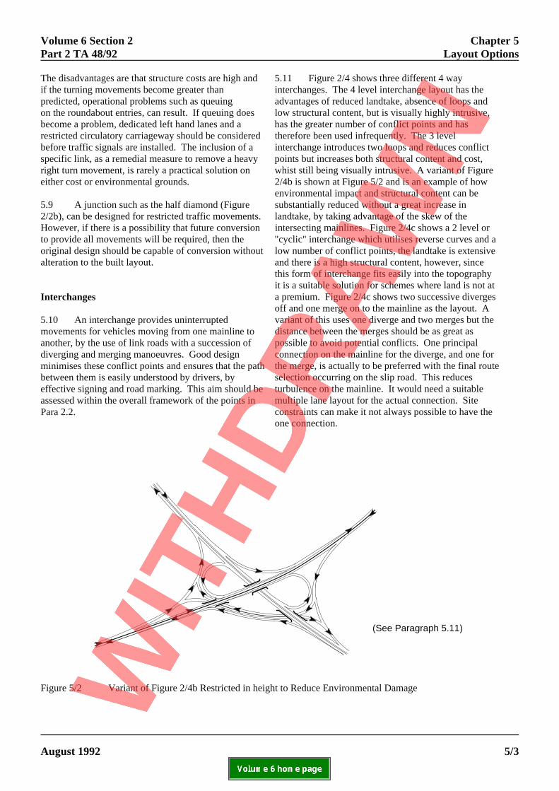
this form of interchange fits easily into the topographyit is a suitable solution for schemes where land is not aa premium. Figure 2/4c shows two successive divergeoff and one merge on to the mainline as the layout. Avariant of this uses one diverge and two merges but thedistance between the merges should be as great aspossible to avoid potential conflicts. One principalconnection on the mainline for the diverge, and one forthe merge, is actually to be preferred with the final routselection occurring on the slip road. This reducesturbulence on the mainline. It would need a suitablemultiple lane layout for the actual connection. Siteconstraints can make it not always possible to have theone connection.
(See Paragraph 5.11)
/2 Variant of Figure 2/4b Restricted in height to Reduce Environmental Damage
FOR USE OUTSIDE THE AGENCY
ONIC DOCUMENT ARE UNCONTROLLED 5/3
Chapter 5 Volume 6 Section 2Layout Options Part 2 TA 48/92
ldhange
e 13)o e. th at
h ),li eh ss
tyvca a Ue
n ated
r ning"ncy
r cilitynt
eed
5.12 The three way "trumpet" interchange shoudesigned to enable future conversion to a four waywithout alteration if this is considered a possibility. Figure 2/4e shows a three way interchange withrestricted movement, this enables high vehicle spebe maintained with low landtake, but it requires a cskew structure and prohibits any future conversion
5.13 Merges can occur within an interchange wthere is a flow imbalance, ie the merging left hand traffic can be greater or equal to the mainline right link traffic. Experience has shown that nonethelespriority should continue to be given to traffic on themainline. If the merging flow is over a lane capacithere will obviously need to be a lane gain. Whatedone, there is a need to ensure that HGVs can reatheir normal positions on the continuing mainline sand expeditiously. Other operational problems havoccurred where the left hand link has been on a lodownhill section and the right hand link uphill, withconsequential disparity in vehicle speeds at the meand this particular layout is not recommended.
5.14 Loops and certain links may require advisospeed limits to warn the driver of the safe negotiatispeed. This speed limit should be used in conjuncwith a bend warning sign and chevron boards toreinforce the hazard warning. Only one level of splimit should be used within an interchange as stepsdown in speed limits will only confuse the driver.
ELECTRONIC COPY - NOT
PAPER COPIES OF THIS ELECTRO5/4
be 5.15 Single lane interchange links can haveconsiderable advantages in cost over 2 lane interc
links for interchanges which contain structures ofsubstantial length. They also have operational
ds to advantages if a merge imbalance occurs (Para 5.stly which needs only a single lane entry at the mainlin
merge. This has advantages of reduced taper leng
ere are near the top of the range (TD 22 (DMRB 6.2.1nk Table 3/1) the uncertainty of the prediction should band recognised (Para 3.1) as the cost of being wrong i
particularly significant and may prohibit laterconversion to a two lane interchange link. A
, disadvantage is that single lane interchange linkser is require closure during maintenance activities.hfely 5.16 Some forms of interchange do not provide
turn facility for maintenance traffic such as gritters,g consequently where there is no other grade separ
junction within an acceptable distance, considerationge, may need to be given to including a "short cut ope
within the interchange for maintenance and emerge
y interchange. The layout and design of any such fag must be approved by the Overseeing Department.ion
congested sites. However, where the predicted flows
vehicles. Figure 5.3 shows an example at a cyclic
(See Paragraph 5.16)
Figure 5/3 Maintenance Connection at X to Provide Southbound U Turn
5.17 For motorway interchanges emergencytelephones should not be sited in an exposed positionthe inside of left hand interchange links with radiibelow Desirable Minimum, as some vehicles have beobserved to cut across the hardshoulder at this point.They should be located on straight or right hand curvsections.
Slip Roads
5.18 Slip roads are part of grade separated junctioand are normally one way. Two way slip roads onlyoccur at half-cloverleaf and trumpet junctions wheretraffic separation is achieved either by a physical cenreserve with safety fences, safety barriers, or a soliddouble white line road marking. Study into the safetyof tight loops (Para 4.4) showed an increased acciderisk for 2 way slip roads as compared to one way. Within the sample both forms of separation wereincluded and the results indicated that a physical barrwill improve safety and reduce cross-over accidents. This is therefore now the standard for such layouts.
5.19 Diverge slip roads can be of a relatively shortlength if the mainline is on a steep down gradient andany case they need not be the same length as mergeroads. If persistent peak hour queuing develops at thslip road exit, backing up on to the mainline willbecome a problem because of the lack of stackingspace, and remedial measures such as part time trafsignals may be required.
5.20 The accident risk for slip roads at junctions issimilar whether the mainline is carried over or under. In order to match mainline vehicle speeds on mergingand reduce them on diverging at the approach to theside road junction the preferred treatment is to designoff-slips uphill and on-slips downhill, with the side roaover the mainline.
5.21 Side road access on to slip roads may berequired in urban areas for junction improvementschemes. The layout should be such that drivers on access are made fully aware of their emergence on toone way slip road by clear signing. The access shounot include a merging lane but terminate at a normalgive way road marking.
ELECTRONIC COPY - NOT
August 1992 PAPER COPIES OF THIS ELECTR
on
en e
ns merge is the only recommended layout when chancarriageway standards from 3 lanes to 2 or 2 to 3 anto 3 or 3 to 4 lanes. The actual layout of the diverge
tral merge should be selected corresponding to the leavor joining flow but under light conditions could be
Figure 2/4d or Figure 2/6c in TD 22 (DMRB 6.2.1). nt Lane drops should remove only the left hand lane a
(excluding climbing lanes) should not take place on link between junctions.
ier5.24 If the proportion of HGVs is greater than 10at a merge on an uphill mainline gradient in excess
be given to the extension of a parallel merging lane in 22 (DMRB 6.2.1.4.18) to the crest. This will enable slip merging drivers to match their speed with those oe mainline.
5.25 Parallel diverging lanes are not recommendfic for entry into loops (except TD 22 (DMRB 6.2.1.4.1
as this has been observed to encourage high speed a
5.26 Urban junction improvements may incorporasafety fences or safety barriers between the mainlinand slip road if there is a speed limit of 50 mph or uon the mainline (TD 19 (DMRB 2.2)). This may hav
d the effect of reducing the inter carriageway sidewaysvisibility and can create operational problems in the
the full range of safety fences and safety barriers isconsidered to see if better visibility can be achieved
the with particular systems. Otherwise the merge nos a taper may be increased in length by 50%.
ld
Merging and Diverging Lanes
5.22 Mainline lane drops within a junction (3 lanesprior to the diverge, 2 lanes between diverge and mergeand then back to 3 lanes) are not generallyrecommended on operational and safety grounds (seePara 4.4). They severely impair future maintenance,especially at interchanges where no reasonablediversion route is available.
5.23 A lane drop or addition at a junction diverge or
2% and within 0.5km of the crest, consideration should
loss of control at the commencement of the loop.
merge area. To allievate this, it is recommended that
Weaving Area
5.27 In calculating the number of traffic lanesrequired (TD 22 (DMRB 6.2.1.2.26)) a fractional partwill inevitably require a decision to round up or down. If it is possible to vary the position of the junctions andthus increase or decrease the weaving length, thefractional part will converge approximately to a wholenumber of lanes and the decision is simplified. However, if this is not possible the decision becomes
FOR USE OUTSIDE THE AGENCY
ONIC DOCUMENT ARE UNCONTROLLED 5/5
Chapter 5 Volume 6 Section 2Layout Options Part 2 TA 48/92
more difficult and it should be reflected in theassessment procedure. Where the fractional part issmall and is combined with a low weaving flowrounding down is suggested, whereas a high fractionalpart with a high weaving volume suggests rounding up. For example the addition of a fourth lane would haveoperational advantages in releasing the two middlelanes for weaving traffic. Other factors which mayinfluence the decision are:
i. the number of lanes required for merging anddiverging (TD 22 (DMRB 6.2.1.2.21 andDMRB 6.2.1.2.23));
ii. when the fractional part is about 0.5 theuncertainty of the predicted flows (Para 3.1)suggests always rounding up from 2-3 lanes;
iii. on recreational routes there can be a highproportion of drivers who are not local andtherefore behave less efficiently thancommuters would at the same flow levels;
iv. in urban areas extra land take is difficult toacquire and is very costly;
v. fully grade separated rural all purpose roadshave operational characteristics approachingthose of motorways and should be treated assuch (TD 22 (DMRB 6.2.1.4.23)).
5.28 Where possible on all purpose roads, theweaving length between junctions and layby/servicearea tapers should be the minimum weaving length asdefined in TD 22 (DMRB 6.2.1), para 4.23 for ruralroads and para 4.24 for urban roads.
Signing and Lighting
5.29 The signing and lighting proposals should beconsidered at the earliest stage of design to ensure thesatisfactory operation of a grade separated junction forall users, including cyclists and pedestrians.
ELECTRONIC COPY - NOT FOR USE OUTSIDE THE AGENCY
PAPER COPIES OF THIS ELECTRONIC DOCUMENT ARE UNCONTROLLED August 19925/6
Volume 6 Section 2 Chapter 6Part 2 TA 48/92 Cyclists and Pedestrians Facilities
ELECTRONIC COPY - NOT FOR USE OUTSIDE THE AGENCY
September 1992 PAPER COPIES OF THIS ELECTRONIC DOCUMENT ARE UNCONTROLLED 6/1
6. CYCLISTS AND PEDESTRIANS FACILITIES
6.1 On motorways, where cyclists and pedestriansare prohibited, they only have to negotiate the at gradepart of the grade separated junction. However, on allpurpose roads, detailed attention to the needs of cyclistsand pedestrians is required throughout the junction.
Cyclists
6.2 Advice is available on the provision offacilities for cyclists in the following documents
- Local Transport Note (1/86) published by theDepartment of Transport
- Traffic Advisory Unit Leaflet (1/88) publishedby the Department of Transport
- Cycling Advice Note 1/89 and 2/89 publishedby the Scottish Office Industry DepartmentRoads Directorate
Consideration should also be given to combinedpedestrian/cyclists subways as outlined in TD 3 (DMRB6.3) and in TA 42 (DMRB 6.2).
Pedestrians
6.3 A grade separated crossing either by subway orfootbridge, can be included to remove conflict betweenpedestrians and vehicles. Advice is contained in TA 42(DMRB 6.2) on the facilities for pedestrians atroundabouts.
Volume 6 Section 2 Chapter 7Part 2 TA 48/92 References
7. REFERENCES
1. Introduction
a. TD 22 (DMRB 6.2.1) - Layout of GradeSeparated Junctions
b. TA 30 (DMRB 5.1) - Choice between optionsfor Trunk Road Schemes
c. The Traffic Signs Manual - Chapters 1,3,4,5and 14 - HMSO
d. TD 18 (DMRB 5.1) - Criteria for the use ofGantries for Traffic Signs and Matrix TrafficSignals on Trunk Roads and Trunk RoadMotorways
2. General Principles
a. TD 22 as Chapter 1
b. TD 9 (DMRB 6.1) - Highway Link Design:Amendment No 1: 1985 and Amendment No 1991
c. The Traffic Signs Manual as Chapter 1
d. TA 23 (DMRB 6.2) - Determination of Size ofRoundabouts and Major/Minor Junctions
e. TD 16 (DMRB 6.2) - The Geometric Design oRoundabouts
f. TA 42 (DMRB 6.2) - The Geometric Design oRoundabouts
g. TA 20 (DMRB 6.2) - The Layout ofMajor/Minor Junctions
h. Traffic Signs Regulations and GeneralDirections 1981 - SI 1981 No 859: HMSO:1981; The Traffic Signs (Amendment)Regulations 1982 - SI 1982 No 1879: HMSO:1982; and The Traffic Signs General(Amendment) Directions 1982 - SI 1982No 1880: HMSO: 1982
i. TA 30 as Chapter 1
ELECTRONIC COPY - NOT
August 1992 PAPER COPIES OF THIS ELECTR
3. Flow Standards
a. TA 23 as Chapter 2
c. Scottish Traffic and Environmental Appraisal
d. TD 22 as Chapter 1
e. LR679 - The Capacity of Motorway Merges;TRRL: 1976
b. TD 9 as Chapter 2
c. TA 20 as Chapter 2.2:
f
f
b. Traffic Appraisal Manual - (TAM): DTp: 1982
Manual (STEAM). Scottish Office 1986
4. Geometric Standards
a. TD 22 as Chapter 1
5. Layout Options
a. TD 19 (DMRB 2.2) - Safety Fences andBarriers: Amendment No 1: 1986
b. TD 32 (DMRB 2.2) - Departmental Standard -Wire Rope Safety Fence
c. "Highway Construction Details" - HMSO(MCHW 3)
d. TA 20 as Chapter 2
e. TA 42 as Chapter 2
f. TD 22 as Chapter 1
6. Cyclists and Pedestrians Facilities
a. TD 3 (DMRB 6.3) - Departmental Standard -Combined Pedestrian and Cycle Subways -Layouts and Dimensions: DTp: 1979
b. TA 42 as Chapter 2
FOR USE OUTSIDE THE AGENCY
ONIC DOCUMENT ARE UNCONTROLLED 7/1
Volume 6 Section 2 Chapter 8Part 2 TA 48/92 Enquiries
ELECTRONIC COPY - NOT FOR USE OUTSIDE THE AGENCY
August 1992 PAPER COPIES OF THIS ELECTRONIC DOCUMENT ARE UNCONTROLLED 8/1
8. ENQUIRIES
All technical enquiries or comments on this Advice Note should be sent in writing as appropriate to:-
Head of Highways Engineering DivisionThe Department of TransportSt Christopher House N S ORGANSouthwark Street Head of Highways EngineeringLondon SE1 0TE Division
The Deputy Chief EngineerRoads DirectorateThe Scottish Office Industry DepartmentNew St Andrew's House J INNESEdinburgh EH1 3TG Deputy Chief Engineer
Head of Roads Engineering (Construction) DivisionWelsh OfficeY Swyddfa GymreigGovernment BuildingsTy Glas Road B H HAWKERLlanishen Head of Roads EngineeringCardiff CF4 5PL (Construction) Division
Superintending Engineer WorksDepartment of the Environment forNorthern IrelandCommonwealth HouseCastle Street D O'HAGANBelfast BT1 1GU Superintending Engineer Works


![Following Acute Encephalitis, Semliki Forest Virus is ... · specialized and regulated [1,2]; the resting CNS, is separated from the blood by the tight endothelial cell junctions](https://static.documents.pub/doc/80x56/5fc2e31a90e4ca5f24284858/following-acute-encephalitis-semliki-forest-virus-is-specialized-and-regulated.jpg)


