LAZYTURN MANUAL 1/30/2010 REV: 5 TABLE OF CONTENTS 1.0 PREFACE 1.1 GENERAL MANUAL COMMENTS 2.0 HOW TO USE THIS MANUAL 3.0 LAZYTURN PROGRAM DEVELOPMENT OVERVIEW 4.0 INSTALLING LAZYTURN 5.0 SCREENS – MENUS - TOOLBAR BUTTONS – STATUS BAR 5.1 MAIN SCREEN 5.2 FILE MENU 5.3 OPTIONS MENU 5.4 EDIT MENU 5.5 VIEW MENU 5.6 DEBUG MENU 5.7 HELP MENU 5.8 TOOLPATH MENU 5.9 FILE FOLDER BUTTON 5.10 ZOOM & FIT BUTTONS 5.11 SELECT TOOL BUTTON 5.12 LATHE TOOLS DIALOG 5.13 DESCRIPTION OF INPUT BOXES FOR LATHE TOOLS\ 5.14 CUT BUTTON 5.14.1 DIAGNOSTICS 5.14.2 SCAN LINE DIAGNOSTICS 5.14.3 VISUAL INTERSECT DIAGNOSTICS 5.15 ERASE TOOLPATH BUTTON 5.16 POST GCODECODE BUTTON 6.0 GRAPHICS AREA 6.1 PROFILE and RULERS 6.2 RULERS 6.2.1 RULER PENTAGONS 6.3 PENTAGON VALUE INPUT 6.4 CROSS HAIR 6.5 MANIPULATION OF THE GRAHIC DISPLAY 6.6 BUTTONS 6.7 PATH PORTRAYAL 7.0 TOOLPATH GENERATION 7.1 TOOLPATHS GENERATION OVERVIEW 7.2 DXF DRAWING 7.3 TOOL CREATION 7.4 MULTIPLE PATHS AND TOOLS 7.5 COMMENTS / REVIEW ON TOOLPATH GENERATION 8.0 POSTING CODE LTR APPENDIX TITLE REV REMARKS A LAZYTURN QUICK AND DIRTY 3 PICS ARE OUTDATED & NEEDS UPDATE B CAD DRAWINGS AND COMMON MISTAKES 3 C DXF FILE EXPORTS 3 D POSTED DXF FILES 2 E PRACTICAL MACHINING CONSIDERATIONS 3 F PC REQUIREMENTS 2 G MACH 3 TURN - QUICK REFERENCE IN DEVELOPMENT - NOT INCLUDED Page 1 of 49
1.7 Thanks to all that have contributed in any way. Without replies and testingthis manual would not be available today. Only one name is noted in the
manual, ART, and to him the community of turners should be thankfull.
“Just so there’s no misunderstandings on this project, I’ll state it clearly," Ipromise nothing, I will endeavor to work on it as often as possible, and with thehelp of those here testing I will make it as lazy and bulletproof as possible, but itwill come as it comes, and develop as it does and as time and circumstance
permits. With luck and perserverance, as well as interest from users ( orpotentiual users) the end result will be a usefull program that is hard to find areplacement for at a reasonable cost." ( You can quote me on that.. ).SO I T WAS SAI D AND I T I S BEI NG ACCOMPLI SHED!
1.8 Verbage in blue is not currently implemented in LazyTurn.
The manual has a natural progression of presenting material as if you never knew what
LazyTurn was. The blue text highlights what is not implemented in the program, Italic
text is commentary on a particular subject, numerous figures are used along with red text
/ arrows / underlines to assist in relating the figure to what is written.
The manual is progressive and there very little duplication. Here is the progression:
- It provides information on the programs concept
- Tells you how to install the software
- Talks about each and every screen, menu, pull down so you know what your see.The information presented stays focused on the material being presented and will refer
to other sections or appendixes to maintain that focus.
- The manual then covers the graphics part of the program and how to move about it.- Tool path creation and numerous figures now show how to use program menus, tool use
at a high level, and creation of the cutting paths- Posting of the Gcode is then presented
You should “read” the complete manual to get a flavor of the software. Then open
LazyTurn and try out the different operations paying attention to what the differentscreens are showing. Then go to section 6 and duplicate the paths using the supplied
DXF drawing and tool inputs. Try different tool input values and combinations and payattention to the results. Review the appendixes for more in depth information.
LazyTurn is a very intuitive program. Don’t hack your way through the program, have
pre-conceived notions on how it should work, or relate it to other programs. Reading the
manual will provide the information necessary to achieving results with the program.
Finally, be practical in the application of LazyTurn.
LazyTurn will be free to those people that licensed LazyCam Pro level.
LAZYCAM TURN will be removed from LazyCam and will be replaced by
LAZYTURN. This program is a DXF or other vector file loader, which then assists iscreating a turning Gcode. It is planned to do boring, facing, roughing, grooving and
finishing (currently being developed ) from an imported profile.
This program will, in the end, also allow for profiles to be drawn. At the moment, all
you can do is load pre-existing dxf's, hpgls, or other vector format data. My concept of this is a quick load of a profile, a fast easy way to set general
relationships between objects, and quick button presses to generate paths. Tools will be a
library of graphical tools so you can see the effects as a path is generated.
What I envision is the toolpath removing the stock, and leaving a subprofile behind of
uncut material which can then be cut with another tool if necessary.
Drawing is planned. And when (if?) LazyTurn is released, turning will be removed from
lazycam.
There are a few CAM packages out there to draw profiles and create paths, their high cost
is due to the complexity of doing all that, and the required support. If I can do a program
that easily imports a DXf and generates toolpaths, I may decide that that’s enough. Itwas never my intent to compete with true CAM contour packages.
Just a note on complexity, it isnt my aim to replace the high end turning modelers out
there, like Dolphin and OneCNC, they do a great job for those that use CAM programs,LazyTurn will continue to be dedicated more to the hobbiest who really just wants an
easier way to generate paths from DXF's,
Keep that in mind, so expect simpler things at first, like simple boring, profileing,
roughing, finishing, facing and grooving. Hi end analysis and milling isn’t likely
to occur, I’ll feel pretty good if you can draw a quick profile, and perform a multi-toolstock to product Gcode list.
Inside cuts won’t get done until we have totally replaced the LazyCam functionality
In the end Id like to allow for drawing of the tool bit, might make for interesting profiles,since the design is really an object to object collision detector, any shape would work intheory not just the current ones.
As of this writing LazyTurn was rewritten to accomplish the finishing pass. The finish
pass is currently only in the testing stage and no posting of it associated code is available.
LazyTurn is a hobby project so there is no set timeline as of this manual update. The
stages of development are as follows:
Stage#1 will be rough paths
Stage#2 will be finish-rough paths
Stage #3 is finish paths. ( currently in testing ) Stage 4 is facing paths.
Stage 5, 6, 7. inside, cutoff, various things….. all optional if I decide to go that far.By end of stage #4 the program should be better than most can get for the price (free) and
I’ll make decisions from there. I really just want to get to the stage where I can remove
turning from LazyCam altogether and replace it with LazyTurn. Seems having it
dedicated to turning makes it easier to do than mixing it into LazyCam.
4.0 INSTALLING LAZYTURN
4.1 LazyTurn ( LT ) currently can be run independently via hard drive, USB stick
etc as it’s installation can stand alone.
4.2 When installing Mach3 you are asked if you also want to install LazyCam.
The current lockdown version of Mach3 installs LazyCam 3.00.2. If you are
using an older version of Mach3 you may need to install the LazyCam 3.00.2Update. Both versions can be downloaded from
the ArtSoft site. Here is the link:
http://www.machsupport.com/downloads
4.3 You can either update LazyCam 3.00.2 by installing the update or create
another directory for a stand alone installation, but both versions must beinstalled for LazyTurn to work.
"LazyCam 3.00.2 Update" is a special build that includes additional requiredfiles.
4.4 Now you will need to update the LazyTurn application file to the most recentversion posted. As of 1/30/2010, The latest application file posted is:
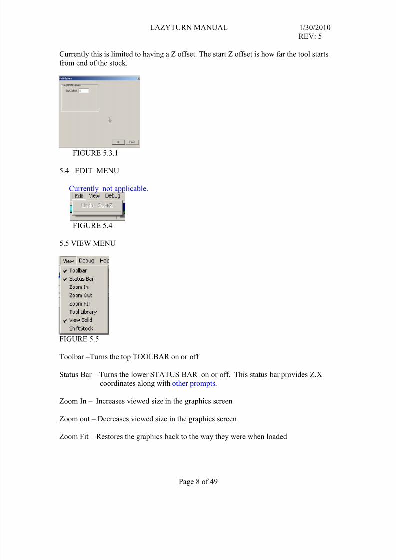
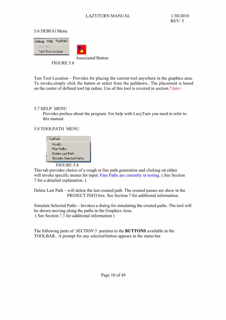
Test Tool Location – Provides for placing the current tool anywhere in the graphics area.To invoke,simply click the button or select from the pulldown.. The placement is based
on the center of defined tool tip radius. Use of this tool is covered in section 7.later
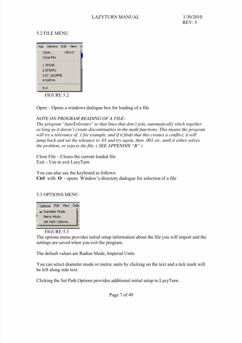
5.7 HELP MENU
Provides preface about the program. For help with LazyTurn you need to refer tothis manual.
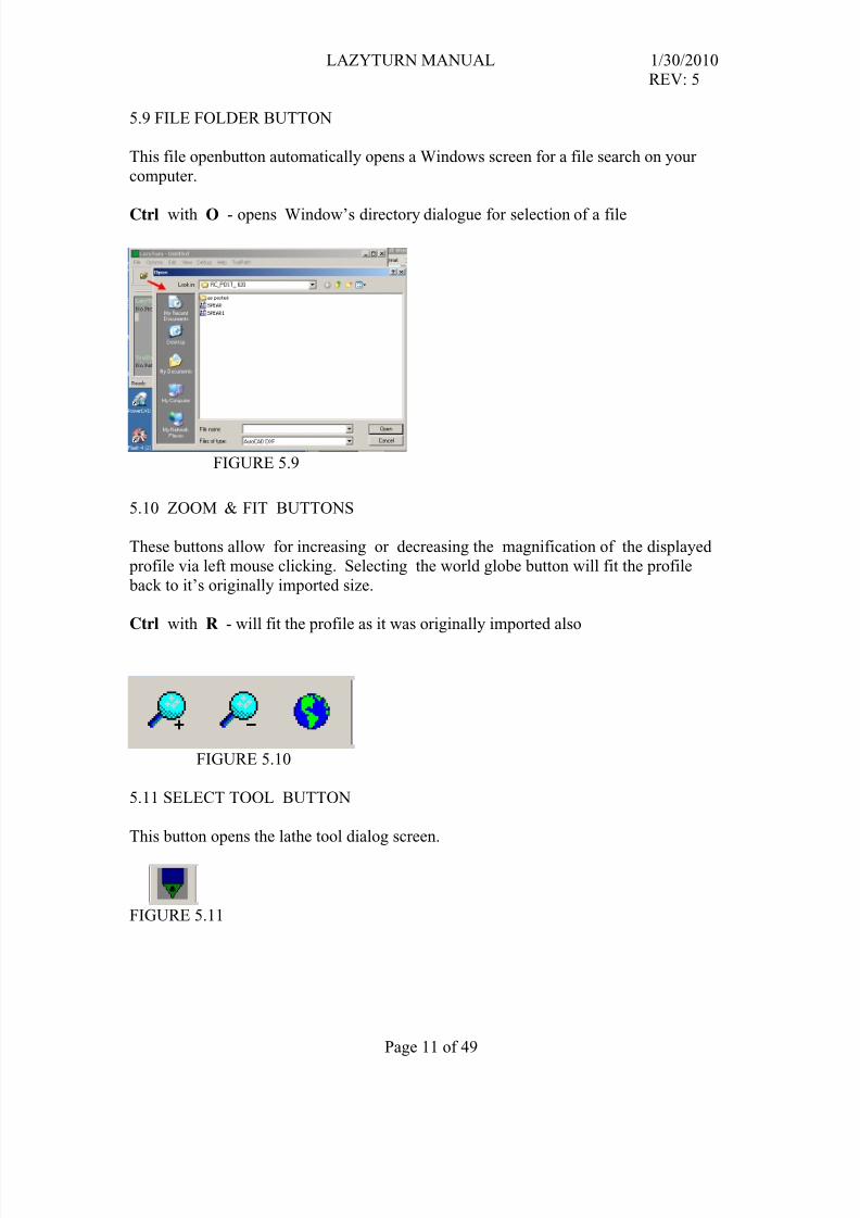
5.8 TOOLPATH MENU
FIGURE 5.8
This tab provides choice of a rough or fine path generation and clicking on eitherwill invoke specific menus for input. Fine Paths are currently in testing. ( See Section
7 for a detailed explanation. )
Delete Last Path – will delete the last created path. The created passes are show in the
PROJECT INFO box. See Section 7 for additional information.
Simulate Selected Paths – Invokes a dialog for simulating the created paths. The tool will
be shown moving along the paths in the Graphics Area.( See Section 7.5 for additional information )
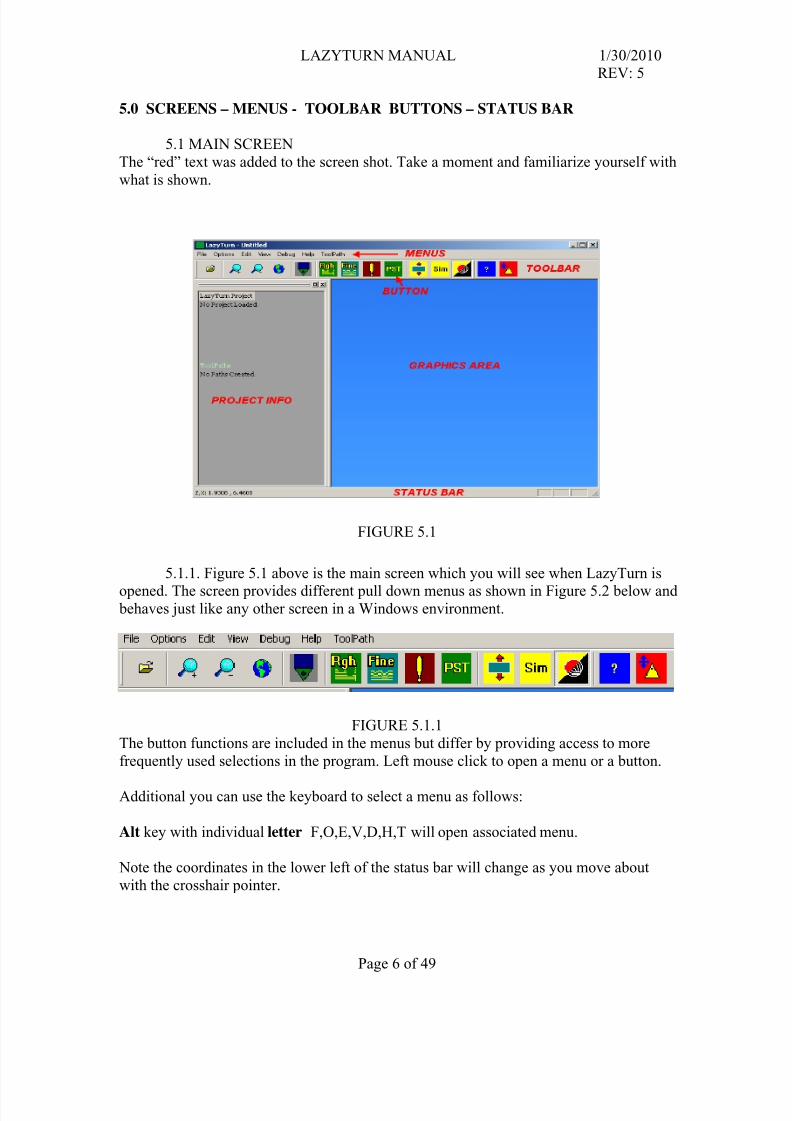
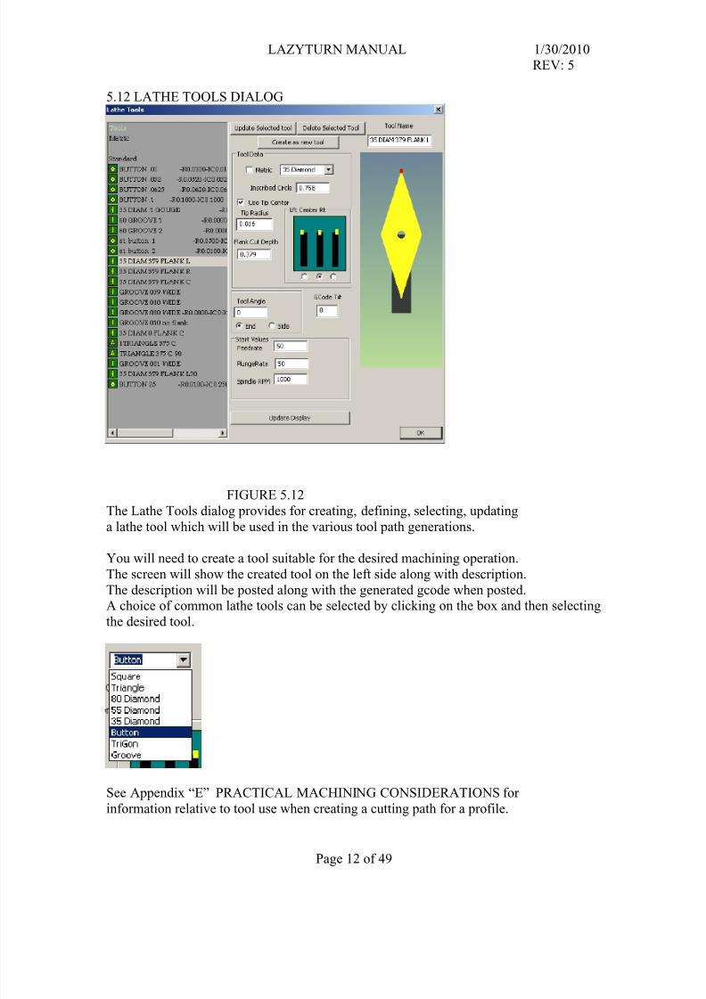
The following parts of SECTION 5 pertains to the BUTTONS available in the
TOOLBAR. A prompt for any selected button appears in the status bar.
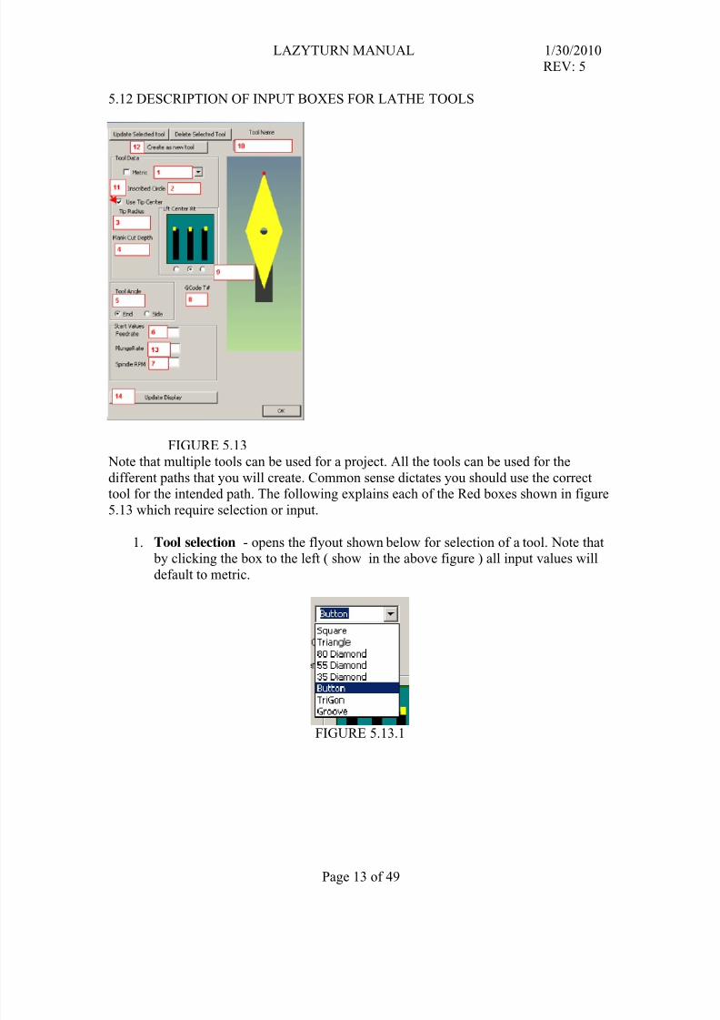
The Lathe Tools dialog provides for creating, defining, selecting, updating
a lathe tool which will be used in the various tool path generations.
You will need to create a tool suitable for the desired machining operation.
The screen will show the created tool on the left side along with description.
The description will be posted along with the generated gcode when posted.A choice of common lathe tools can be selected by clicking on the box and then selecting
the desired tool.
See Appendix “E” PRACTICAL MACHINING CONSIDERATIONS for
information relative to tool use when creating a cutting path for a profile.
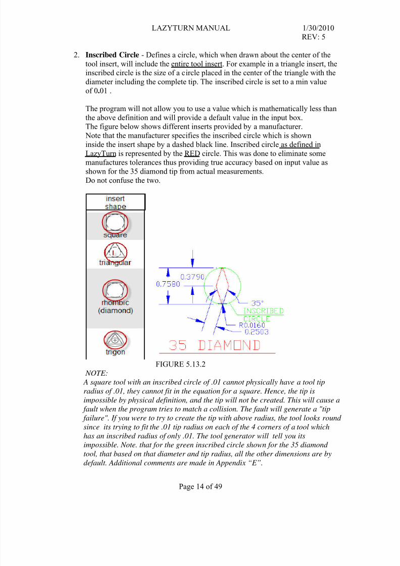
2. Inscribed Circle - Defines a circle, which when drawn about the center of the
tool insert, will include the entire tool insert. For example in a triangle insert, theinscribed circle is the size of a circle placed in the center of the triangle with the
diameter including the complete tip. The inscribed circle is set to a min value
of 0.01 .
The program will not allow you to use a value which is mathematically less than
the above definition and will provide a default value in the input box.The figure below shows different inserts provided by a manufacturer.
Note that the manufacturer specifies the inscribed circle which is shown
inside the insert shape by a dashed black line. Inscribed circle as defined in
LazyTurn is represented by the RED circle. This was done to eliminate somemanufactures tolerances thus providing true accuracy based on input value as
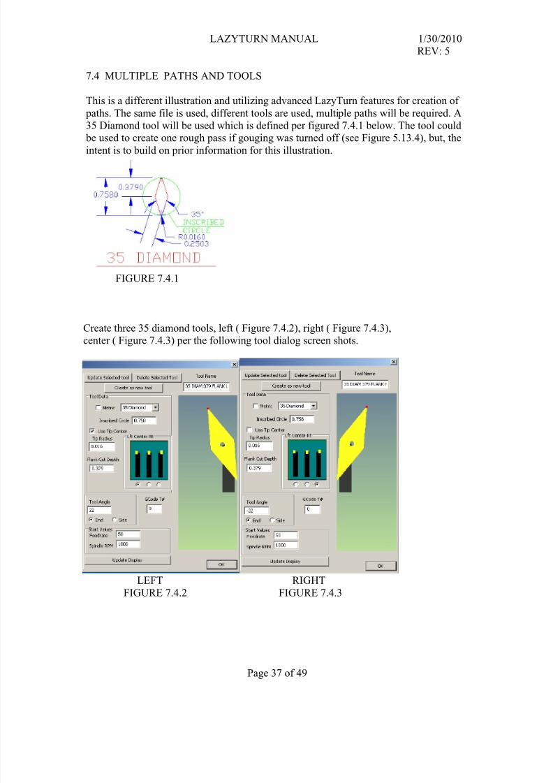
shown for the 35 diamond tip from actual measurements.
Do not confuse the two.
FIGURE 5.13.2 NOTE:
A square tool with an inscribed circle of .01 cannot physically have a tool tip
radius of .01, they cannot fit in the equation for a square. Hence, the tip is
impossible by physical definition, and the tip will not be created. This will cause a
fault when the program tries to match a collision. The fault will generate a "tip
failure". If you were to try to create the tip with above radius, the tool looks round
since its trying to fit the .01 tip radius on each of the 4 corners of a tool which
has an inscribed radius of only .01. The tool generator will tell you its
impossible. Note. that for the green inscribed circle shown for the 35 diamond
tool, that based on that diameter and tip radius, all the other dimensions are by
default. Additional comments are made in Appendix “E”.
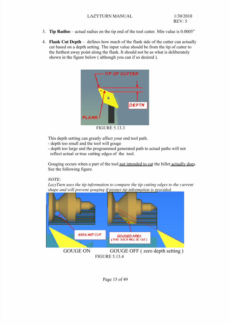
You can use the center tool post or use a value of zero if you do not care about stockgouging.
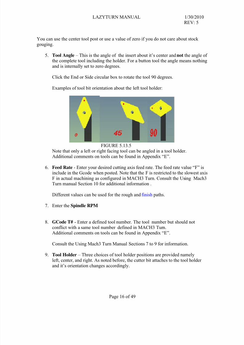
5. Tool Angle – This is the angle of the insert about it’s center and not the angle of
the complete tool including the holder. For a button tool the angle means nothingand is internally set to zero degrees.
Click the End or Side circular box to rotate the tool 90 degrees.
Examples of tool bit orientation about the left tool holder:
FIGURE 5.13.5 Note that only a left or right facing tool can be angled in a tool holder.
Additional comments on tools can be found in Appendix “E”.
6. Feed Rate - Enter your desired cutting axis feed rate. The feed rate value “F” isinclude in the Gcode when posted. Note that the F is restricted to the slowest axis
F in actual machining as configured in MACH3 Turn. Consult the Using Mach3Turn manual Section 10 for additional information .
Different values can be used for the rough and finish paths.
7. Enter the Spindle RPM
8. GCode T# - Enter a defined tool number. The tool number but should not
conflict with a same tool number defined in MACH3 Turn.Additional comments on tools can be found in Appendix “E”.
Consult the Using Mach3 Turn Manual Sections 7 to 9 for information.
9. Tool Holder – Three choices of tool holder positions are provided namely
left, center, and right. As noted before, the cutter bit attaches to the tool holder
10 . Tool Name - This box allows you to name the tool you are creating or rename /
update an existing name. The name, tip radius, inscribed circle are underin the standard listing of the tools ( see Figure 5.12 ).
11. Use Tip Center - when selected will discriminate between using Mach3's offset
registers with compensation, or just to create the code as pre-compensated usingthe tip radius as that compensation from tip center.
Additional comments on tools can be found in Appendix “E”.
Consult the Using Mach3 Turn Manual Sections 7 to 9 for information.
12. To Update a tool simply select the tool on the left by clicking the left mouse button, modify an input and click the “Update Selected Tool box”.
To Delete a tool simply select the tool on the left by clicking the left mouse button and click the “Delete Selected Tool” box.
To Create a tool simply fill in all the inputs, update the display if you so desireto see what it looks like, type a name in box and then click the “Create as new
tool” box.
13. Plunge Rate – Provides for an X feedrate that is different than the Z feedrate.
Here's why: when the tool is moved (X direction) into the stock to begin the next (Z direction) cut, it plunges into
the material and initially has to cut a lot of material all at once. After it starts traveling in the Z direction it's
only cutting from half of the cutter tip and I've chosen a feed rate that's appropriate for this. But every time it
plunges in for another cut it cuts from both sides of the tip simultaneously, removing too much material too fast.
If I slow the feed rate to match this X cut, I waste too much time on the Z cuts. I need different, independently set
feed rates for cuts in the X and Z directions.
14. Update Display – clicking this button will update the graphic display of the tool.
LazyTurn provides a choice of how machining of the profile can be done. Normal use
would be to make larger roughing cuts to remove the bulk of the material from the billet
and then do smaller finishing cuts. You can do multiple roughing and finishing cuts with
different tools until the machining is complete. The generated pathing will follow theorder of the cuts you create.
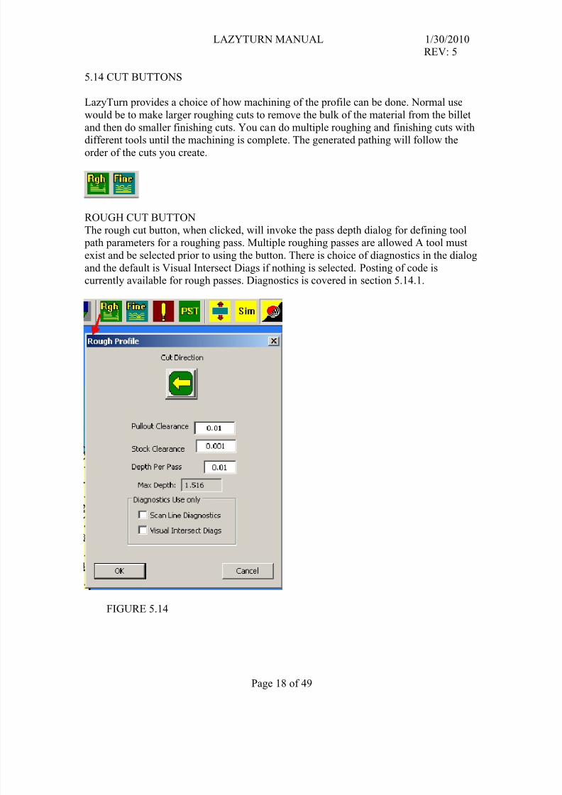
ROUGH CUT BUTTON
The rough cut button, when clicked, will invoke the pass depth dialog for defining tool path parameters for a roughing pass. Multiple roughing passes are allowed A tool must
exist and be selected prior to using the button. There is choice of diagnostics in the dialog
and the default is Visual Intersect Diags if nothing is selected. Posting of code is
currently available for rough passes. Diagnostics is covered in section 5.14.1.
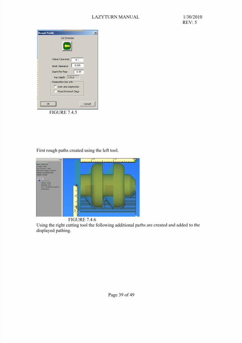
Cut Direction – clicking this button will alternately change a middle tools cutting side
from left to right. Default is left side. A middle mounted tool can cut in either direction.The button is not applicable for a left or right tool and an error message will appear if
clicked.
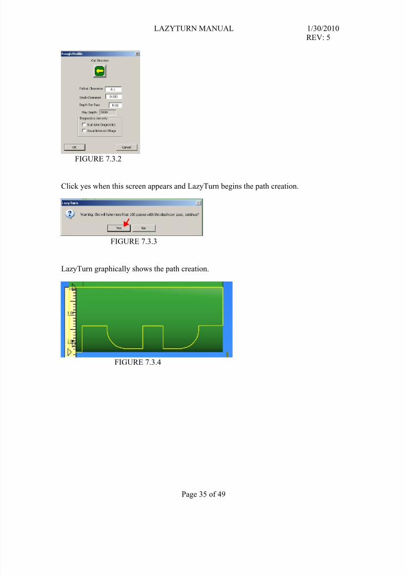
Pullout Clearance - input value defines how far the tool will retract in the X directionduring pathing moves. It is not currently restricted.
Stock Clearance - input value defines the amount of un-cut stock that remains after a
pass.
Max Depth – No input required or allowed.The number is simply a limitation, based on the tool, of how deep you can cut. A tool can
only be used to cut to its inscribed circle depth, and the end max depth is the inscribed
circle, but compensated by diameter or radius mode selection. It stabilizes the operation
of the programs volume calculator.
Depth per Pass - is the how deep each individual pass will cut.
Cancel – clicking on the button will cancel the path process
OK – clicking on the button will allow the path process to start
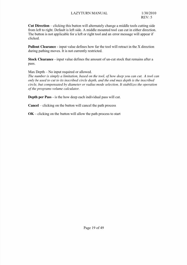
I strongly suggest the reader follow the finish pass development as of this writing.
This verbiage is just rough / preliminary and will surely change.I would suggest staring at page 118 of the LazyTurn thread.
The finish cut button, when clicked, will invoke the pass depth dialog for defining tool path parameters for a finishing pass. Multiple finish passes are allowed. A tool must exist
and be selected prior to using the button.. Posting of finish pathing code is currently notavailable. Finishing is currently being tested and as such a only a visual display of the
finish cut provided as shown in the left below.
Path Name – allows for providing a unique name for the finish. The name appears in the
Project Info.
Clearance – The amount of material to be left on the profile after the finsh pass is done
Final Pass – The depth of the last path / cut of the finish pass
Per Pass – Max pass depth of any pathing associated with the finish pass
Tolerance- This setting defines how many times the software will look ahead or alongthe profile as it is creating the pathing. The range of acceptable input values are 0.0001”
to 10. The finer the tolerance the closer the LazyTurn will monitor it’s analysis. The
setting will impact how long it takes to generate the pathing. So it will take more time for
a long piece of say 30 inches overall length than one of say 6”.
Diagnostics – later
Cancel – clicking on the button will cancel the path process
OK – clicking on the button will allow the path process to start
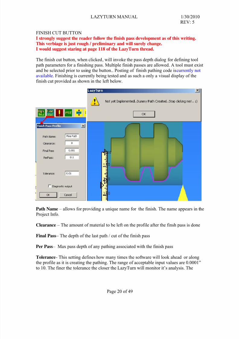
5.14.1 DIAGNOSTICS
You have two choices in the selection of what diagnostics will be done by clickingone the boxes shown in the figure below.
FIGURE 5.14.1 NOTE: You currently can post code if you use the diagnostics. This WAS NOT allowed in older versiosn
and is being clarified as of this writing .
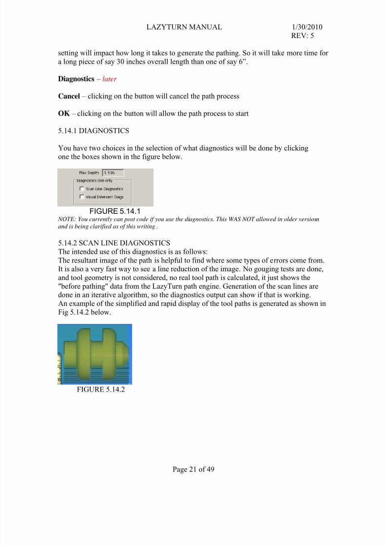
5.14.2 SCAN LINE DIAGNOSTICS
The intended use of this diagnostics is as follows:
The resultant image of the path is helpful to find where some types of errors come from.It is also a very fast way to see a line reduction of the image. No gouging tests are done,
and tool geometry is not considered, no real tool path is calculated, it just shows the
"before pathing" data from the LazyTurn path engine. Generation of the scan lines aredone in an iterative algorithm, so the diagnostics output can show if that is working.
An example of the simplified and rapid display of the tool paths is generated as shown in
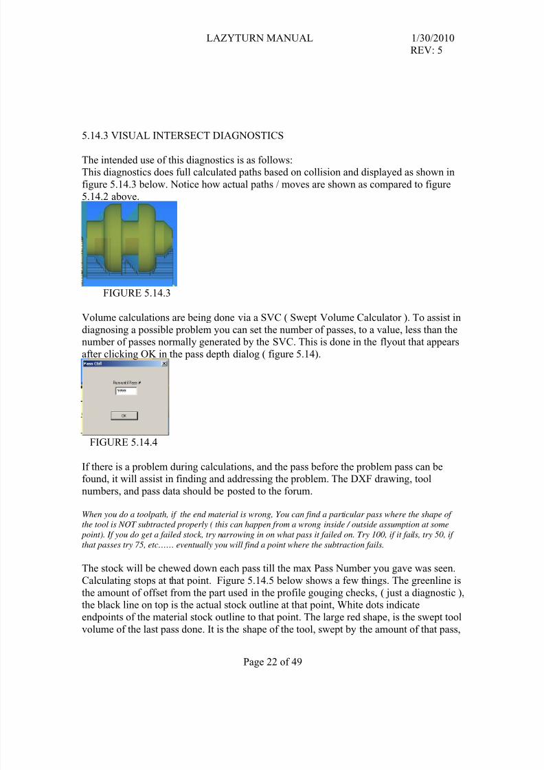
The intended use of this diagnostics is as follows:This diagnostics does full calculated paths based on collision and displayed as shown in
figure 5.14.3 below. Notice how actual paths / moves are shown as compared to figure
5.14.2 above.
FIGURE 5.14.3
Volume calculations are being done via a SVC ( Swept Volume Calculator ). To assist in
diagnosing a possible problem you can set the number of passes, to a value, less than thenumber of passes normally generated by the SVC. This is done in the flyout that appears
after clicking OK in the pass depth dialog ( figure 5.14).
FIGURE 5.14.4
If there is a problem during calculations, and the pass before the problem pass can befound, it will assist in finding and addressing the problem. The DXF drawing, tool
numbers, and pass data should be posted to the forum.
When you do a toolpath, if the end material is wrong, You can find a particular pass where the shape of
the tool is NOT subtracted properly ( this can happen from a wrong inside / outside assumption at some
point). If you do get a failed stock, try narrowing in on what pass it failed on. Try 100, if it fails, try 50, if
that passes try 75, etc…… eventually you will find a point where the subtraction fails.
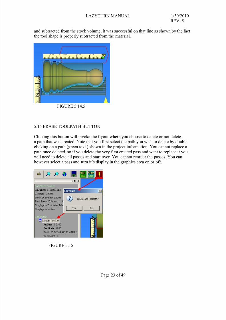
The stock will be chewed down each pass till the max Pass Number you gave was seen.
Calculating stops at that point. Figure 5.14.5 below shows a few things. The greenline is
the amount of offset from the part used in the profile gouging checks, ( just a diagnostic ),the black line on top is the actual stock outline at that point, White dots indicate
endpoints of the material stock outline to that point. The large red shape, is the swept tool
volume of the last pass done. It is the shape of the tool, swept by the amount of that pass,
and subtracted from the stock volume, it was successful on that line as shown by the fact
the tool shape is properly subtracted from the material.
FIGURE 5.14.5
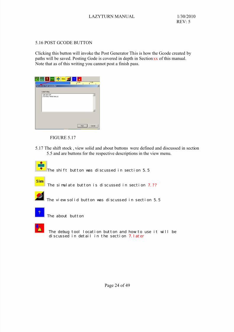
5.15 ERASE TOOLPATH BUTTON
Clicking this button will invoke the flyout where you choose to delete or not deletea path that was created. Note that you first select the path you wish to delete by double
clicking on a path (green text ) shown in the project information. You cannot replace a
path once deleted, so if you delete the very first created pass and want to replace it youwill need to delete all passes and start over. You cannot reorder the passes. You can
however select a pass and turn it’s display in the graphics area on or off.
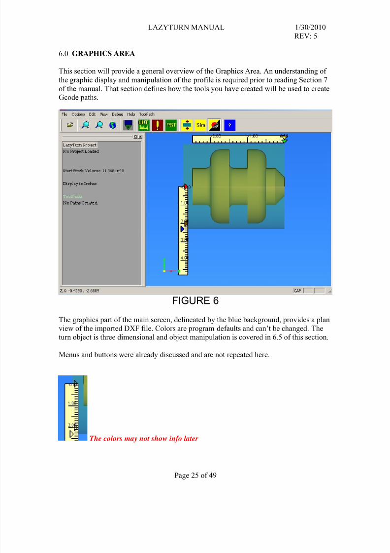
This section will provide a general overview of the Graphics Area. An understanding of
the graphic display and manipulation of the profile is required prior to reading Section 7
of the manual. That section defines how the tools you have created will be used to create
Gcode paths.
FIGURE 6
The graphics part of the main screen, delineated by the blue background, provides a planview of the imported DXF file. Colors are program defaults and can’t be changed. The
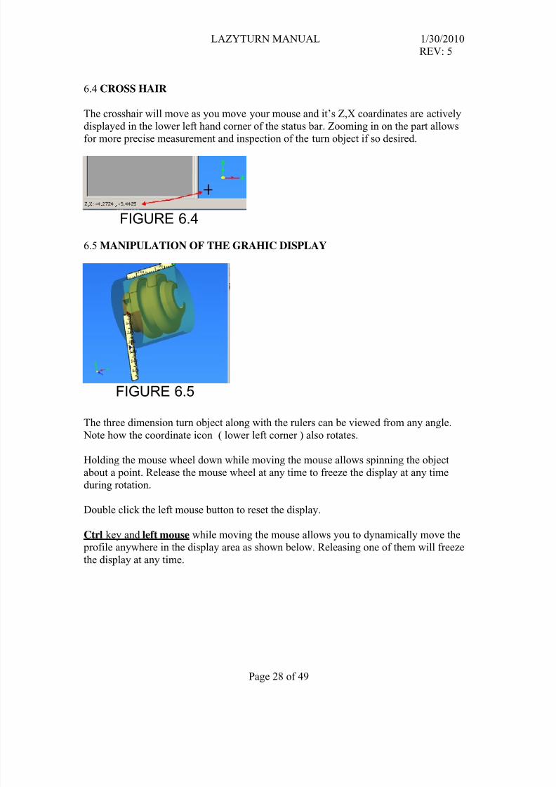
turn object is three dimensional and object manipulation is covered in 6.5 of this section.
Menus and buttons were already discussed and are not repeated here.
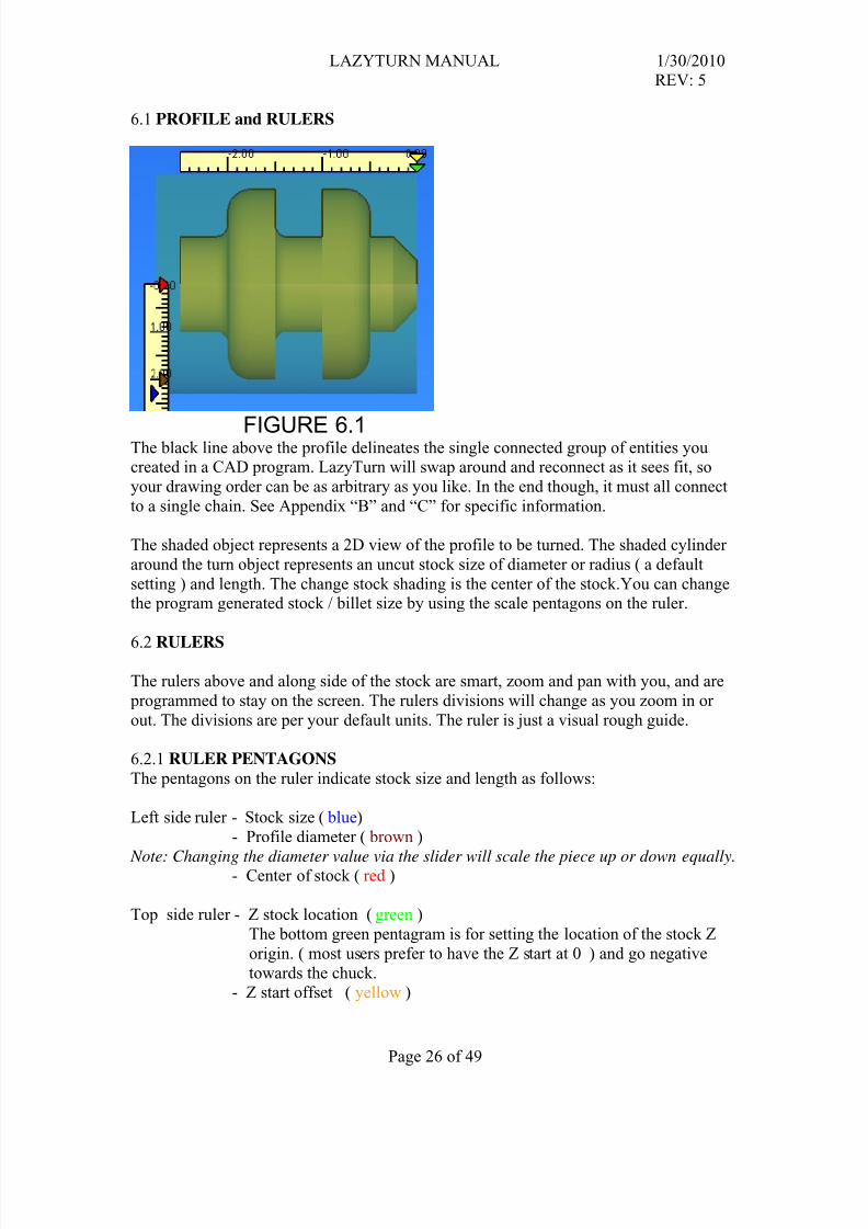
FIGURE 6.1The black line above the profile delineates the single connected group of entities youcreated in a CAD program. LazyTurn will swap around and reconnect as it sees fit, so
your drawing order can be as arbitrary as you like. In the end though, it must all connect
to a single chain. See Appendix “B” and “C” for specific information.
The shaded object represents a 2D view of the profile to be turned. The shaded cylinder
around the turn object represents an uncut stock size of diameter or radius ( a default
setting ) and length. The change stock shading is the center of the stock.You can changethe program generated stock / billet size by using the scale pentagons on the ruler.
6.2 RULERS
The rulers above and along side of the stock are smart, zoom and pan with you, and are
programmed to stay on the screen. The rulers divisions will change as you zoom in or
out. The divisions are per your default units. The ruler is just a visual rough guide.
6.2.1 RULER PENTAGONS
The pentagons on the ruler indicate stock size and length as follows:
Left side ruler - Stock size ( blue)
- Profile diameter ( brown )
Note: Changing the diameter value via the slider will scale the piece up or down equally.- Center of stock ( red )
Top side ruler - Z stock location ( green )
The bottom green pentagram is for setting the location of the stock Z
origin. ( most users prefer to have the Z start at 0 ) and go negative
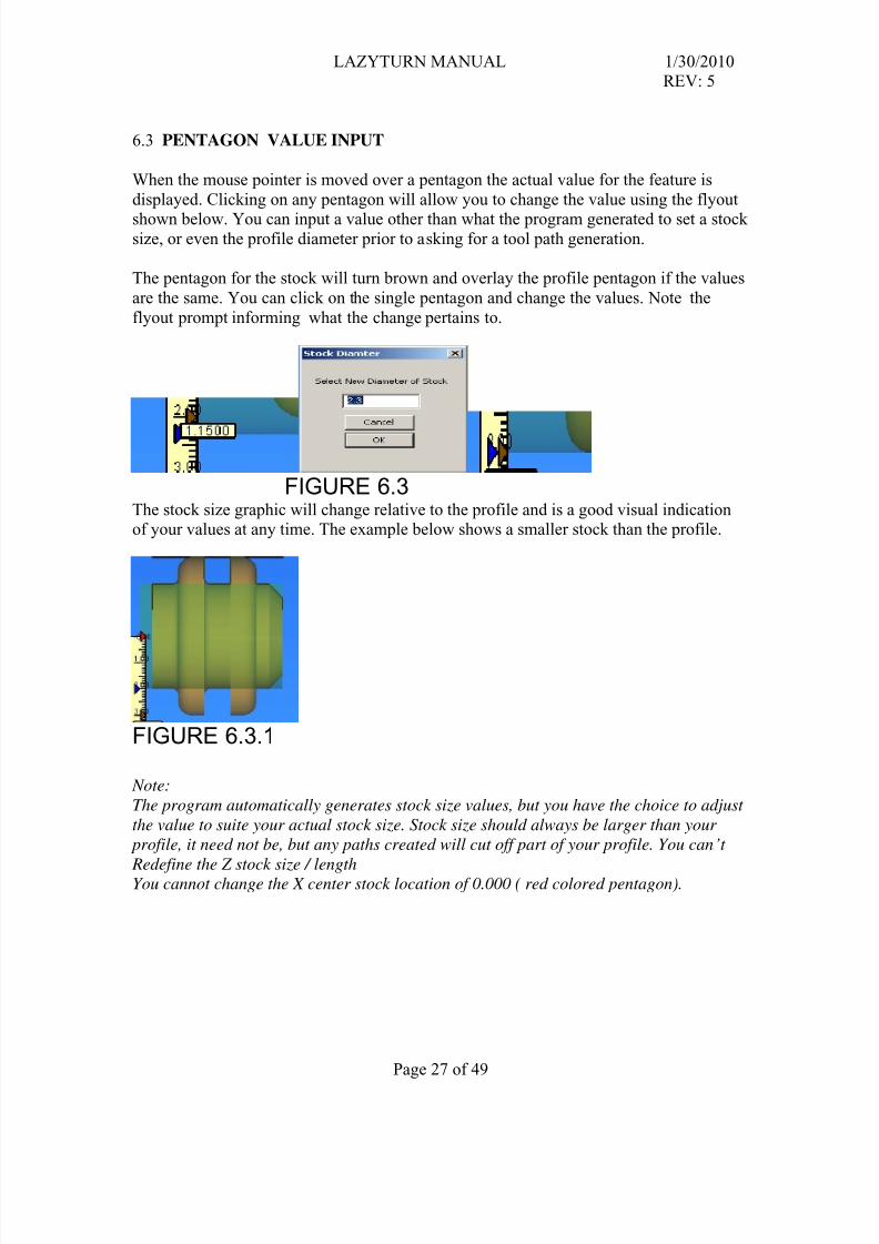
When the mouse pointer is moved over a pentagon the actual value for the feature is
displayed. Clicking on any pentagon will allow you to change the value using the flyout
shown below. You can input a value other than what the program generated to set a stocksize, or even the profile diameter prior to asking for a tool path generation.
The pentagon for the stock will turn brown and overlay the profile pentagon if the values
are the same. You can click on the single pentagon and change the values. Note the
flyout prompt informing what the change pertains to.
FIGURE 6.3The stock size graphic will change relative to the profile and is a good visual indicationof your values at any time. The example below shows a smaller stock than the profile.
FIGURE 6.3.1
Note:
The program automatically generates stock size values, but you have the choice to adjust
the value to suite your actual stock size. Stock size should always be larger than your
profile, it need not be, but any paths created will cut off part of your profile. You can’t
Redefine the Z stock size / lengthYou cannot change the X center stock location of 0.000 ( red colored pentagon).
Shift key and left mouse while moving the mouse up and down on the pad allows you to
dynamically zoom in and out on the profile as shown below. Releasing one of them willfreeze the display at any time.
Profile Zoom in of Profile
FIGURE 6.5.2
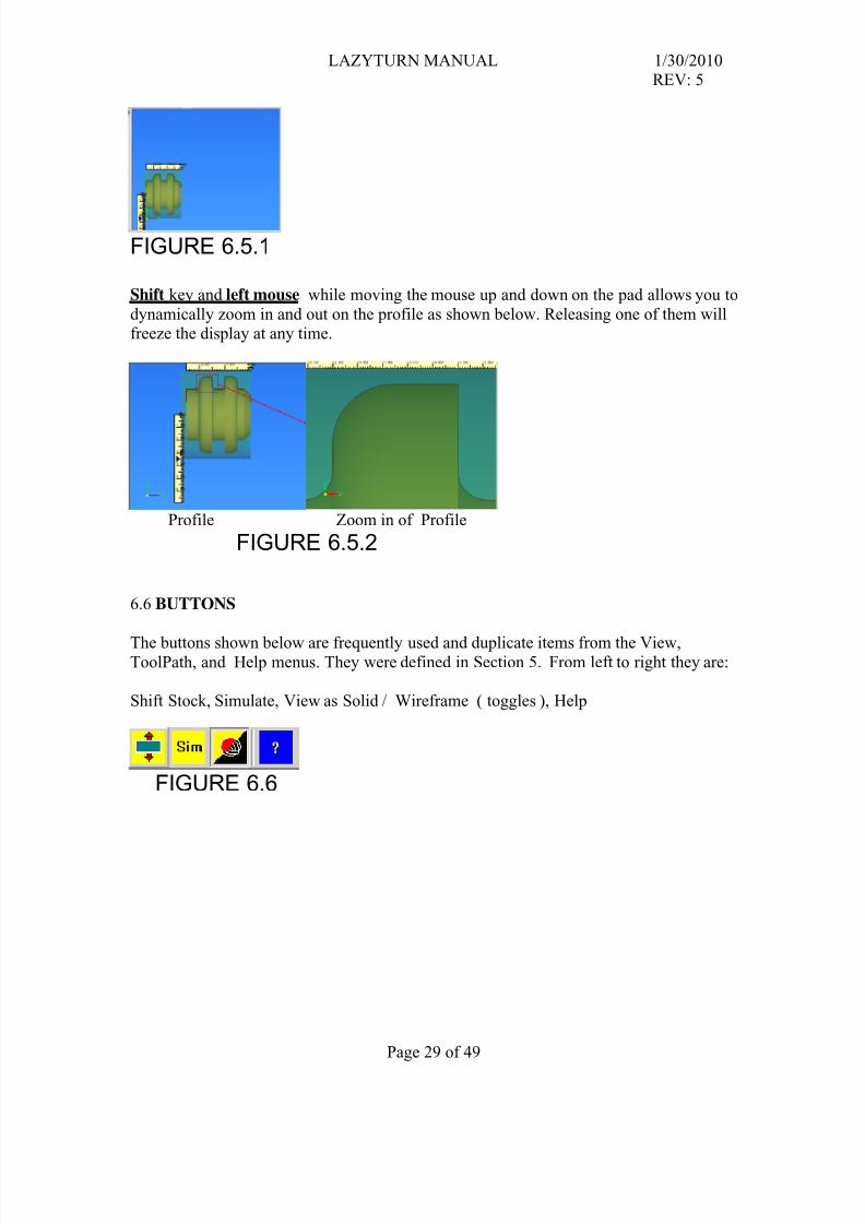
6.6 BUTTONS
The buttons shown below are frequently used and duplicate items from the View,ToolPath, and Help menus. They were defined in Section 5. From left to right they are:
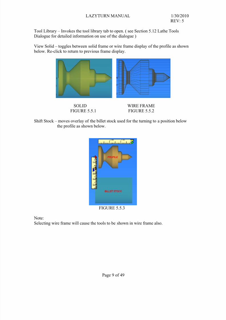
Shift Stock, Simulate, View as Solid / Wireframe ( toggles ), Help
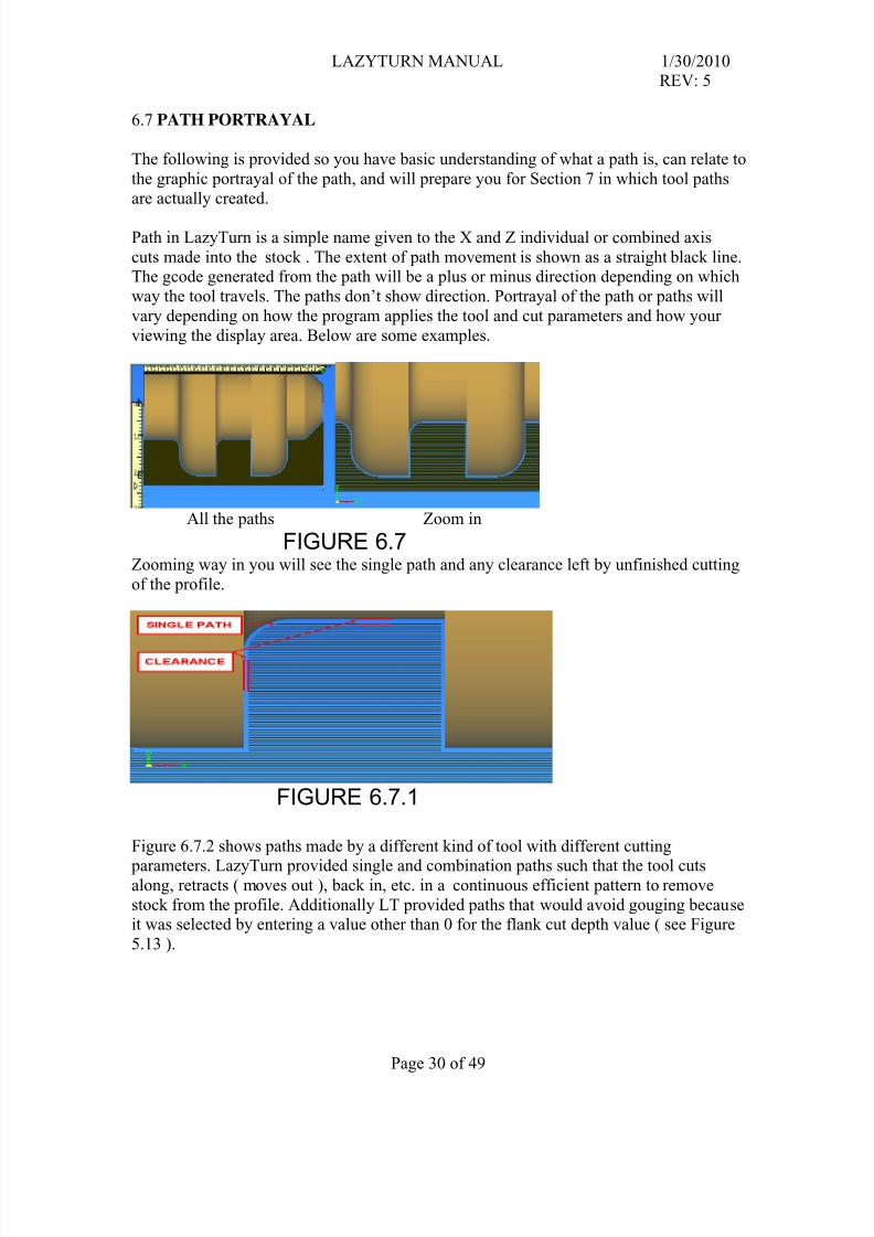
The following is provided so you have basic understanding of what a path is, can relate to
the graphic portrayal of the path, and will prepare you for Section 7 in which tool paths
are actually created.
Path in LazyTurn is a simple name given to the X and Z individual or combined axis
cuts made into the stock . The extent of path movement is shown as a straight black line.The gcode generated from the path will be a plus or minus direction depending on which
way the tool travels. The paths don’t show direction. Portrayal of the path or paths will
vary depending on how the program applies the tool and cut parameters and how your
viewing the display area. Below are some examples.
All the paths Zoom in
FIGURE 6.7Zooming way in you will see the single path and any clearance left by unfinished cutting
of the profile.
FIGURE 6.7.1
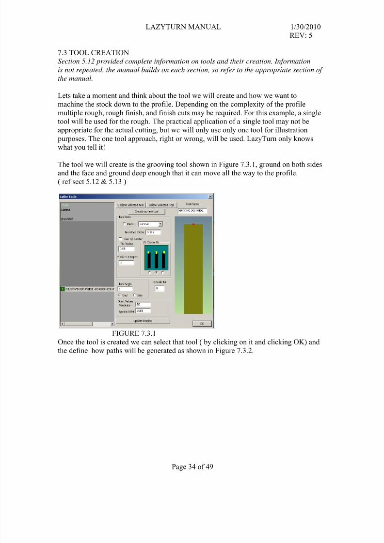
Figure 6.7.2 shows paths made by a different kind of tool with different cutting
parameters. LazyTurn provided single and combination paths such that the tool cutsalong, retracts ( moves out ), back in, etc. in a continuous efficient pattern to remove
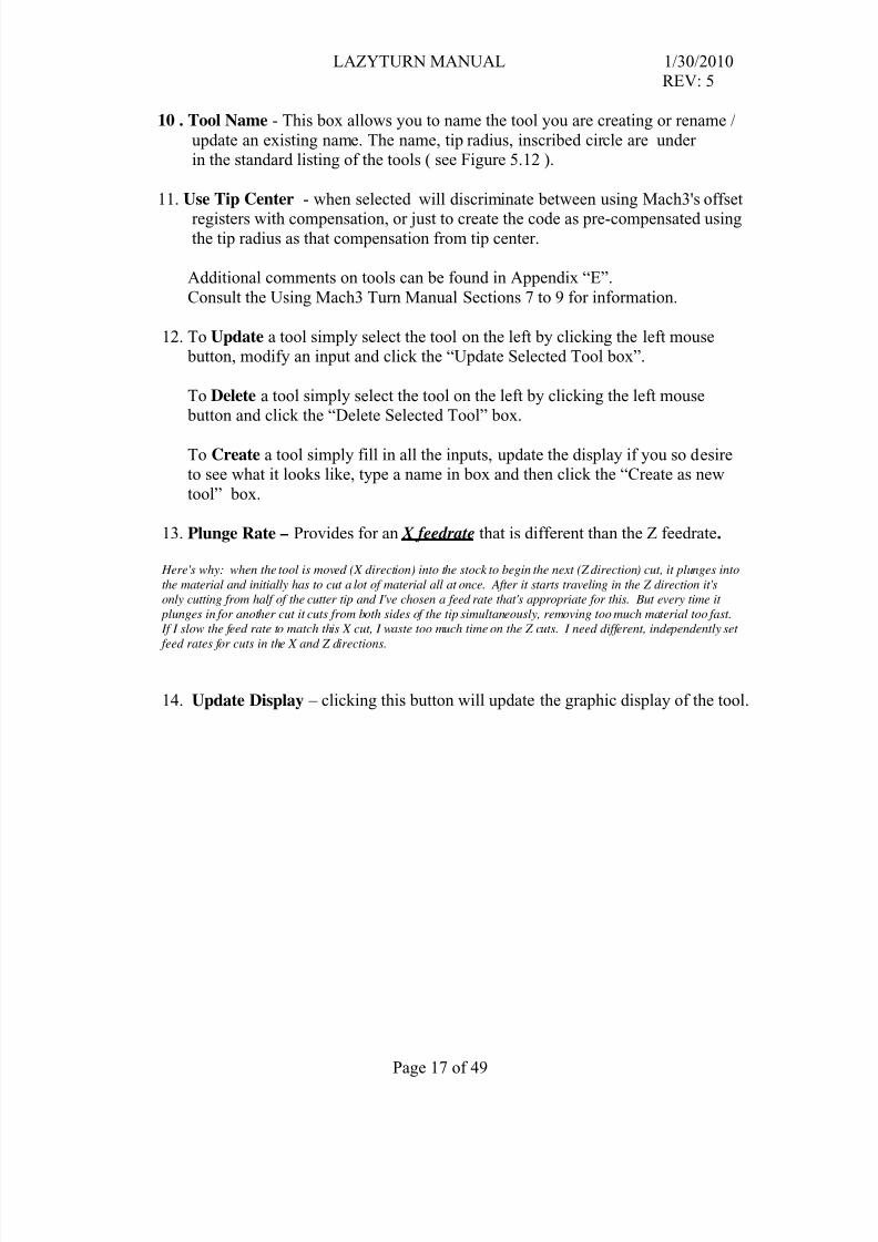
stock from the profile. Additionally LT provided paths that would avoid gouging becauseit was selected by entering a value other than 0 for the flank cut depth value ( see Figure
FIGURE 6.7.2To dynamically watch the cutting in operation just click the “Simulate” button .You will need to create a tool and a tool path before you can Simulate.
This section describes how paths are created. Program information which was covered in
previous sections of the manual will not be repeated although reference to sections may
be noted. The Menus, Buttons, along with their associated dialog and flyouts will be
used.
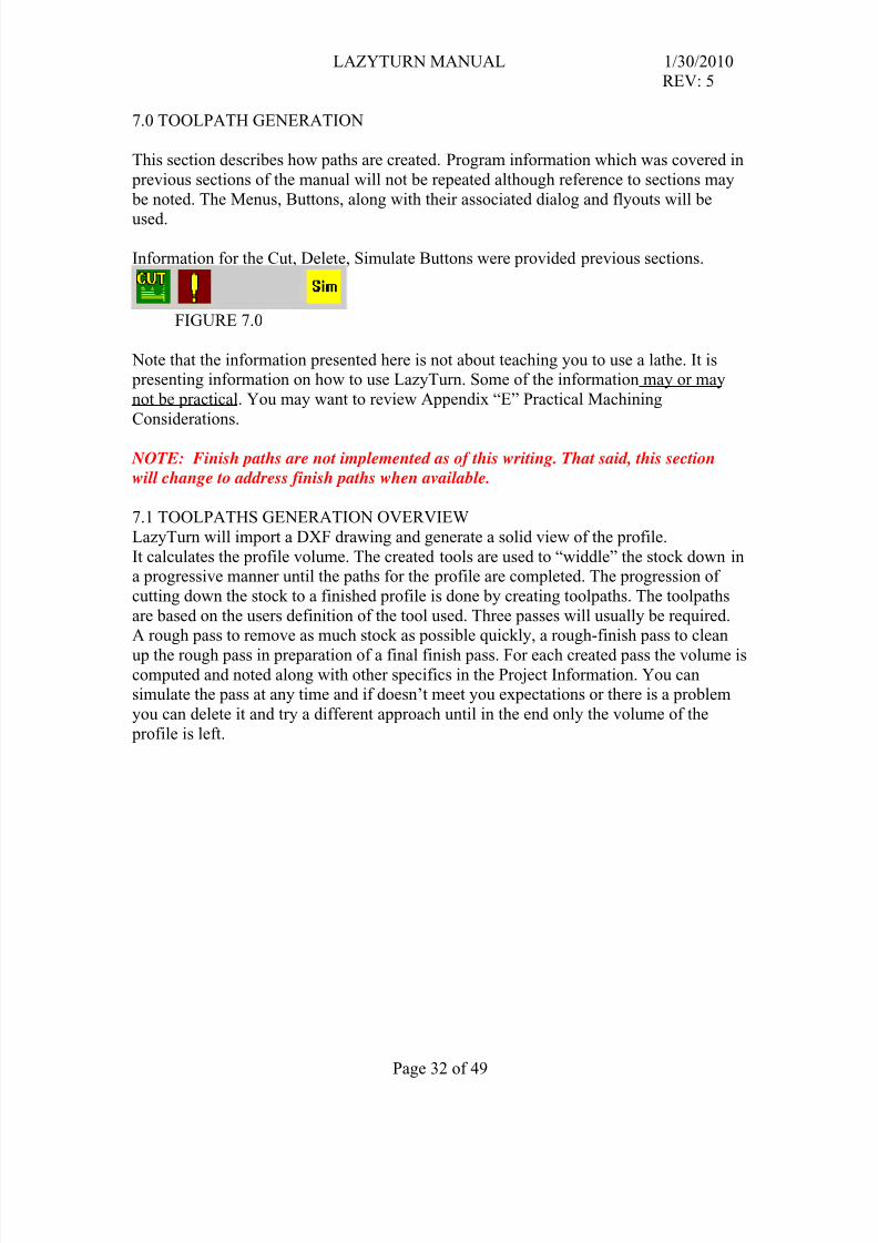
Information for the Cut, Delete, Simulate Buttons were provided previous sections.
FIGURE 7.0
Note that the information presented here is not about teaching you to use a lathe. It is presenting information on how to use LazyTurn. Some of the information may or may
not be practical. You may want to review Appendix “E” Practical Machining
Considerations.
NOTE: Finish paths are not implemented as of this writing. That said, this section
will change to address finish paths when available.
7.1 TOOLPATHS GENERATION OVERVIEW
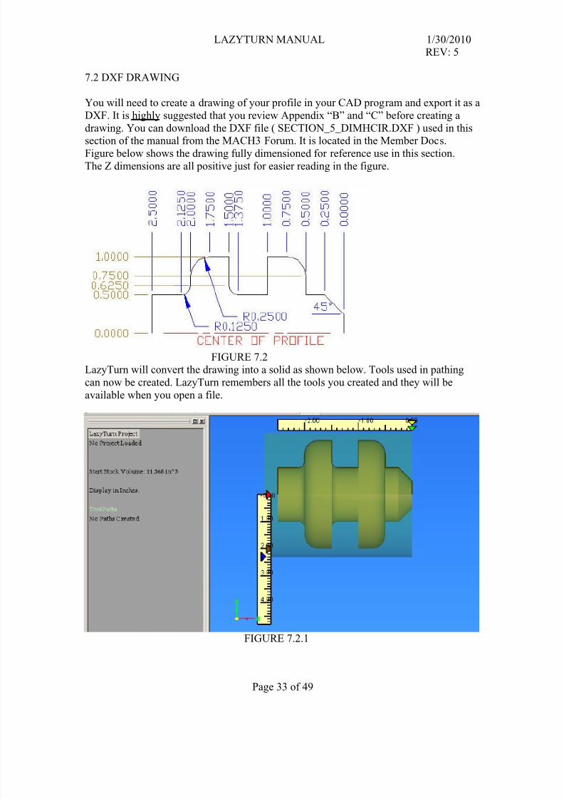
LazyTurn will import a DXF drawing and generate a solid view of the profile.
It calculates the profile volume. The created tools are used to “widdle” the stock down ina progressive manner until the paths for the profile are completed. The progression of
cutting down the stock to a finished profile is done by creating toolpaths. The toolpaths
are based on the users definition of the tool used. Three passes will usually be required.A rough pass to remove as much stock as possible quickly, a rough-finish pass to clean
up the rough pass in preparation of a final finish pass. For each created pass the volume iscomputed and noted along with other specifics in the Project Information. You cansimulate the pass at any time and if doesn’t meet you expectations or there is a problem
you can delete it and try a different approach until in the end only the volume of the
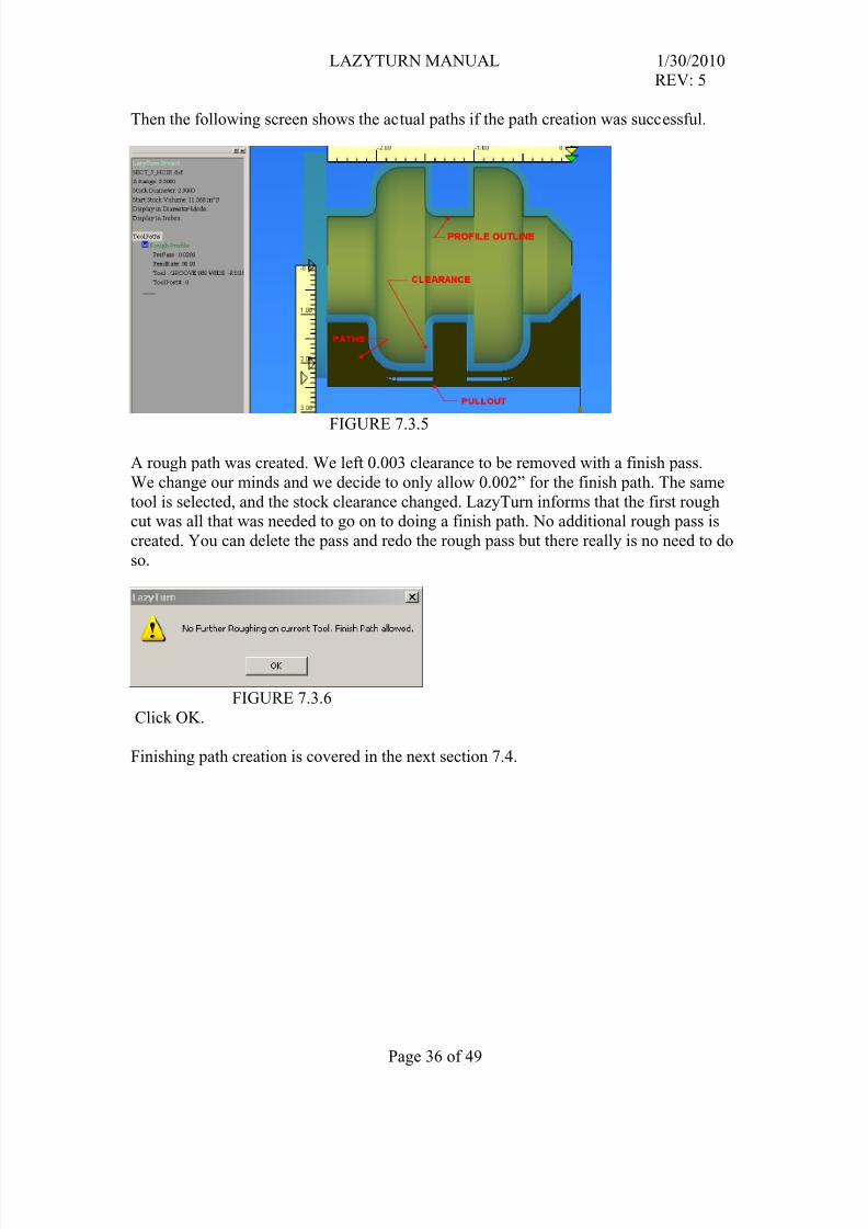
Then the following screen shows the actual paths if the path creation was successful.
FIGURE 7.3.5
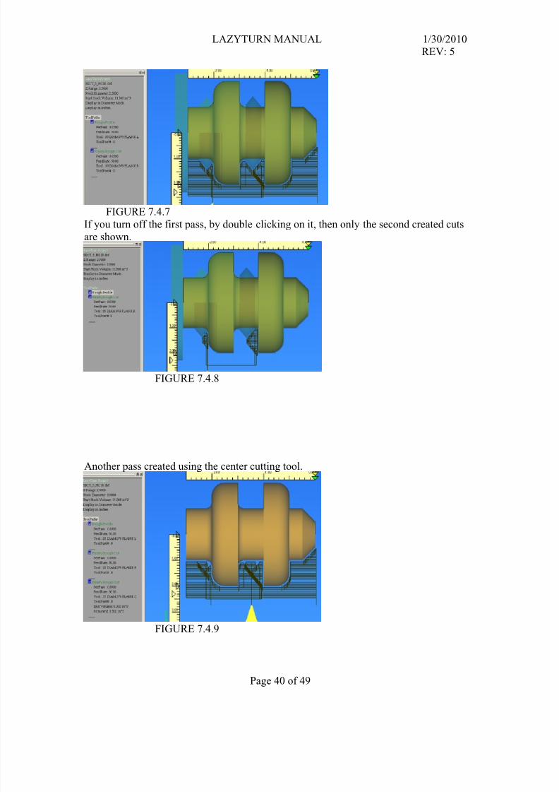
A rough path was created. We left 0.003 clearance to be removed with a finish pass.
We change our minds and we decide to only allow 0.002” for the finish path. The same
tool is selected, and the stock clearance changed. LazyTurn informs that the first roughcut was all that was needed to go on to doing a finish path. No additional rough pass is
created. You can delete the pass and redo the rough pass but there really is no need to do
so.
FIGURE 7.3.6
Click OK.
Finishing path creation is covered in the next section 7.4.
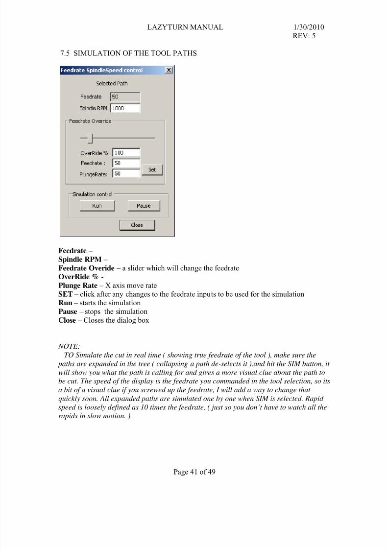
Feedrate Overide – a slider which will change the feedrate
OverRide % -
Plunge Rate – X axis move rateSET – click after any changes to the feedrate inputs to be used for the simulation
Run – starts the simulation
Pause – stops the simulation
Close – Closes the dialog box
NOTE:
TO Simulate the cut in real time ( showing true feedrate of the tool ), make sure the
paths are expanded in the tree ( collapsing a path de-selects it ),and hit the SIM button, it
will show you what the path is calling for and gives a more visual clue about the path to
be cut. The speed of the display is the feedrate you commanded in the tool selection, so itsa bit of a visual clue if you screwed up the feedrate, I will add a way to change that
quickly soon. All expanded paths are simulated one by one when SIM is selected. Rapid
speed is loosely defined as 10 times the feedrate, ( just so you don’t have to watch all the
"Is it possible to shift the X origin (zero position) to the outer diameter of the starting stock so that setup operations whether using
wizard or LazyTurn G-code are similar? "
Most all programs have X=0 as the origin for their code because it can be a repeatable place to easily find / reference to, along with a
number of other reasons. There are a lot of ways of accomplishing what you ask. Depends on how "you" want to work and yourunderstanding of Mach3 Turn.
For now here is MY suggestion for when in MACH3Turn:
Zero world X and Z which ( cancels any G54 so there are no offsets ) and set home somewhere away from the piece, move the tool
"controlled point" to where the gcode for the part was created, click part zero X & Z, ( now machine=program=part cords at the same
point ) move the tool to where you want to start cutting, cycle start the program and all should work just fine. That's a mouth full, but, just one way of working that will keep you out of trouble. I hope!
Depends on the gcode generated by each Wizard. I am not sure they are all a like on where the first move starts from. That said, don't
let you heart be troubled, for there will be a section in the LazyTurn manual which will include information about Mach3 Turn.
prep moves from or to a point, including how to use use / create a tooltable, what impact use of using the tool tip radius vrs using the
offsets which may have been created already. Program / machine / part coordinates relationships, how setting home can be used, an
overview of Mach3Turn, etc etc etc.......whatever the verbage turns out / or needs to be. That will be put into the manual after the
finish paths are available and whatever Art decides to do from a post processing point of view.
Simply put, I hope to cover Mach3Turn at some level in an appendix, the verbage will not conflict with the Using MAch3 Turnmanual. The current four screens, are as they were created before my time, can be confusing if you don't have a good grasp of the
whole program. I will see if i can capture the the compete program visually in about four pages or so.
This is all work in progress from here on!Multiple tool cuts. Each one building from the previous. one button, "Cut" , which will BUT if no material will be removed, the user
will be prompted as such and asked if he
would like a "finish pass" to be performed. So if a user presses Cut twice without changing tools, he will be prompted for a finish pass
authorization. On the other hand, if material CAN be removed, ie: the tool or direction was changed, the systemwill simply add just another rough pass only on the material left over from previous passes.
This means Users will not be able to decide on their own to do a finish pass and no button will exist for one, LTurn will only trigger
a finish pass when a cut is requested with a tool that cannot remove any further material with rough pass.Its my hope this will firstly ensure that no tool can be hurt by improper finish passes that attempt to take away too much
material for the tool's previous passes, and reduce the amount of decisions made by the user as well as reducing the number
of buttons to two, one for tool selection, and one for CUT.
Only the areas uncut are now processed You may use multiple tools or multiple depths in any order. However, since all cuts are predicated on the previous cut, the delete toolpath button ( !) will only remove the final cut, which you can then recut, or delete
upwards on the tree one by one.
The plan for fiinish hprofile is to have the CUT button do a finish ONLY if the previous CUT took no material at all , meaning theroughing is now done.
It will be mandatory to make a rough pass? the way it functions is to do a rough if material exists that shoudl be roughed, only do a
finish if the tool is done. I will look into perhaps making it just finsh if no rough seems necessary, but the way the algorithms work I
think it needs to compute the rough ..
No, you be able to just double click cut and get a request for a finish pass the checking is mandatory as it performs many of the main
calculations needed.
Yes, you will be able to post at any time, or just on specific stages.
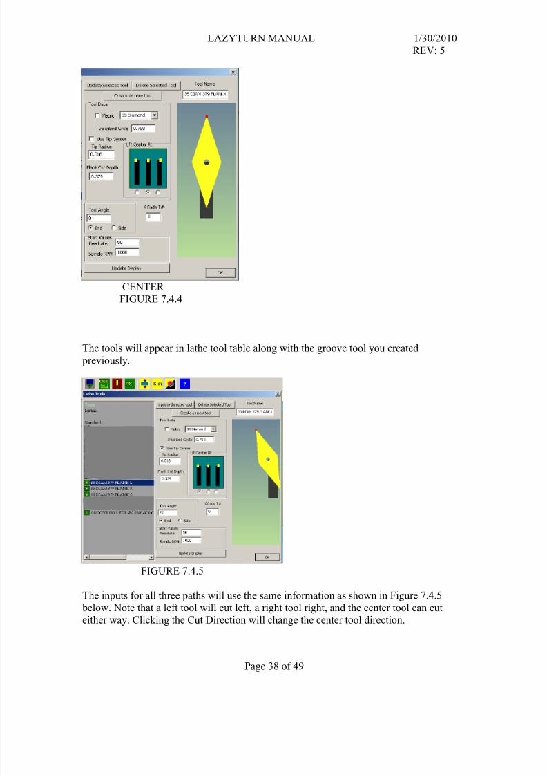
Center and left facing tools will cut Right to Left, and Right facing tools will cut left to right.
PROFILE TURNINGOptionally, A third button, FACE, will be added then to allow for the entire job to rotate 90 degrees on the screen to allow for the
other two buttons to be used identically, only in facing operations instead of profiling. That will leave only the final
optional button, BORE to be added for inside operations should I decide to go LazyTurn is a profiler only.
7X GENERAL User defined tools may be added in the future. The tool, in the end after designing it, will simply be a profile used mathematically todetect collisions in creation of the path , so a user defined tool and holder, perhaps as a DXF will be importable.
7.6 GENERAL TOOL CONSIDERATIONS
The shape of the tool will be important in LTurn, as it will be a graphic object calculating
any collisions in the path, and also remaining and wont try to cut it again after roughing
and such.
The tools creation still requires work., but for the most part it is possible to create tools
that should mimic your tools fairly well if you use inserts, if not, then you could generate
tools that simply have a tool radius about equal to your ground tool, and with an almostnon-existent tool holder.
A user defined tool may be implemented later based on a DXF to be imported as the shape of a tool. When any tool is created, youARE really creating a dxf of a tool that will be used in the collision dynamics to create the tool paths it should be possible to allow a
dxf based tool creator for special tools.
The toolholder it will be made to conform more to the user in the future, and its shape will be taken into account for the generation ofthe Gcode later.
7.7 ROUGH PASS
Roughing is the quick removal of bulk of material, done quickly, with a large cut depthand short chips, it is not meant to be smooth just quick. You can use a special tool with
other parameters (roughing with a very small tooltip is asking for broken tools) and a
heavier body then finishing tools. The bigger the work piece the more important roughing
will be.
The fact that multiple rough passes may be necessary, that to is already in the code, butits completion requires the fine-rough stage to be a valid one as its inputs conditions will
be used by the second or third rough pass. Its input conditions are calculated by the first
rough pass. So I need to progress a bit further before you begin to see secondaryroughing.
In all cases the tools will be unrestricted and any can be used on any stage.
7.8 ROUGH FINISH PASSRoughing as a step can leave larger chunks than one would want to take in a finish pass,so a definition of "Fine-Rough" is a step that reduces the chucks to a size manageable by
a finish tool. ( typically the same tool as the finish pass would be generated with).
Basically its a safety pass to clean up the profile so that a proper finish pass can be
applied without hurting the finish tool. Any tool can be used for any pass, but by allowing
The toolpath generated by the lazyturn will be the exact piece and mach3 will manage the
tool radius compensation OR Lazyturn will create a toolpath that already includes thetooltip radius compensation ?
My suggestion is that mach3 compensates the tool radius. In this way a user is free to use
its cam software. For example I made a program to do just that, translate a dxf into gcode,
but the final object differs because of the radius of the tools. I must draw it alreadythinking on the tool and make some calculations that is difficult and easy to make
mistakes.
7.11 BORING
Boring is currently not available.
I would be curious on your internal boring thoughts. Would it be easy ( selectable
from external by some simple definition? Would the profile need to be drawn differently?What kind of tool.....some standard boring bar with cutters.......or ….Would you be able
to draw your boring bar / tool shape and let the program check for clashes?Internal boring would be done with a slightly different profile. It would be a profilewith a straight outer edge so the program knows by inference that its internal cutting.
As to tool shape, a draw able tool shape (or profile) may be used and available when
implemented.
7.12 TOOL RADIUS
What is the purpose or practicality of having a tip radius of less than .0005" .Forgive
me if I fail to see why an effort has to be made to reduce this to 0.
I'm the culprit pushing for a real small tip radius. It doesn't have to be less than .001".
I selected that as the smallest value because practically speaking never been able grind /
hone one down to less than that number. In fact .002" to .004" is probablymore like it when touched up. Most will never be able to actually measure it.
For all intents and purposes there is no real good reason, a radius of .0005 is
effectively 0.0 in real world terms. It means an error tolerance of .001 ( inch or mm) in a
profile, so it has no real effect. Internally however, I just have to ensure low values aretreated fairly for the sake of stability.
TOOL TIP DISCUSSION
Allow one tool, maybe the button tool for representing a point tool with almost no width for turning of
small stuff even if it doesn't make sense.
LT won’t allow such tools to exist.
Illegal circ/tip combinations are not allowed
Program not complete, it wont warn you, it will just make a tool that is as close as you can physically get.
Preliminary thoughts on any of the tool restriction's.Will there be any difference between restrictions of
say a roughing or finishing tool?ie; The total tip must fit into an inscribed circle of “x" for a button tool or
“x" / different for each of the other tool's.
What would be the smallest tip radius? ( 0.001" is a tough one practically speaking, but 0.002 to .004" is
not) Can the min holder width be equal to the tip radius?
My concern is that because of the clash detection / and you can't turn it off / tip radius is say restricted
to .010" / or no profile code generation , that turning of small items will suffer, thus code generation for the
model maker won't be easly available.
Fooling with it now, the tool tip failure is nice.And even if code is posted i see that the code is not right
and the roughing cuts are lacking in the gcode.
No real restriction, it just has to have a shape, and the shape must be real. For example, an incribed circle of 1mm cannot have
tip radii of 5mm, the radisu is larger than the size of the tool itself. Inscribed circle tells the program how
large the tool is, the tp radius really shoudl be able to be set to zero, a sharp point on the tip, that will
happen soon. An inscribed circle is , for those unaware, the largest circle that can be placed on the tool
without extending off the edges. Tip radisu is the roundness of the pointy parts.
SO the only real concern in the end is that I don’t allow you to specify mathematically impossible
shapes. I hope to allow you to draw a shape in the end.. I wrote the collision detection to take into account
any shape at all, not matter how complex, though it will slow the algorithms that check the gouge. Slowness
will be the main issue, though I have not as yet tried to optimize speed at all, I’m more worried about
accuracy and safety.
You may use any tool, but the graphic that shows the amount left to cut will be wrong, the toolpath however
will be correct on any tool. I need to fix the graphics for "amount cut"
TOOLS
SQUARE
TRAINGULARDIAMOND 80,55,35
BUTTON
TRIGON
GROOVE
Grooving parting tools will be usable but pathing is not implemented yet.
the way to do grooves is to use 2 offsets, for example if we use tool 7 we would use say offset 7, offset 7 would have a X and a Z
offset for the diameter and the front edge of the tool, offset 17 would have the same X offset as offset 7 but the Z offset would be for
the back edge of the tip.
Our tool tip is 1.5mm wide, we set our diameter datum as normal, we touch the front edge of the tip on the front of the job and setour Z offset, e.g. -100 The offset for the back of the tip would be entered into offset 17 as Z-101.5, that will put the back edge of the
tip at the end of the job if we entered in MDI 'G00 Z0 T0717'
Most grooving tools have a radius to stop them snipping the edge, the idea of the 2 offsets is to compensate for wear and maintain
position.
My thought on the grooving tool is to still set a tip radius, this sets the internal 0 point of the tip, so the X and Z offsets are implied bythat. In your example tool then, if one specifed a tip radius appropriately, then the X and Z offset are implicit. So if you zeroed to the
back edge of the tool, with no X,Z offsets setup , your actually changing the side tolerancess well as the tip end. Though in your case
that may not suffice. Ill look at that for you when I do a grooving tool sequence. We may have to have a dual offset, but as it stands ,(
at least in my head) I think a general tool tip radius even for a grooving tool should create the right offsets. ( Though zeroing may
require a knowledge about if your zeroing to the left or right of the tool. ). But that I expect may be true of any tool since tip radial
center is the important setting for the tool. Not a problem in generation of code as direction is considered in terms of the cut, butzeroing will be the important function in that regard. But Im not sure I see a differecne between the grooving tool or any other tip in
that regard.
for actual code generation, motion direction will account for the path,
zeroing I suspect is the problem in terms of setup.. On the other hand, if we just leave offsets to zero, and use a tip radius as the
complete
setup in MAch3 for that tool. ( taking wear registers into account) , then really no offset should be necessary... hmm, gotta think aboutthat one for MDI usage, my though was to eliminate the G41/G42 requirment by using tip center as the Gcode output default, thus
making the output precompensated as to offsets other than tip radius.. Im still comig to grips with that internally though, so I guessall I
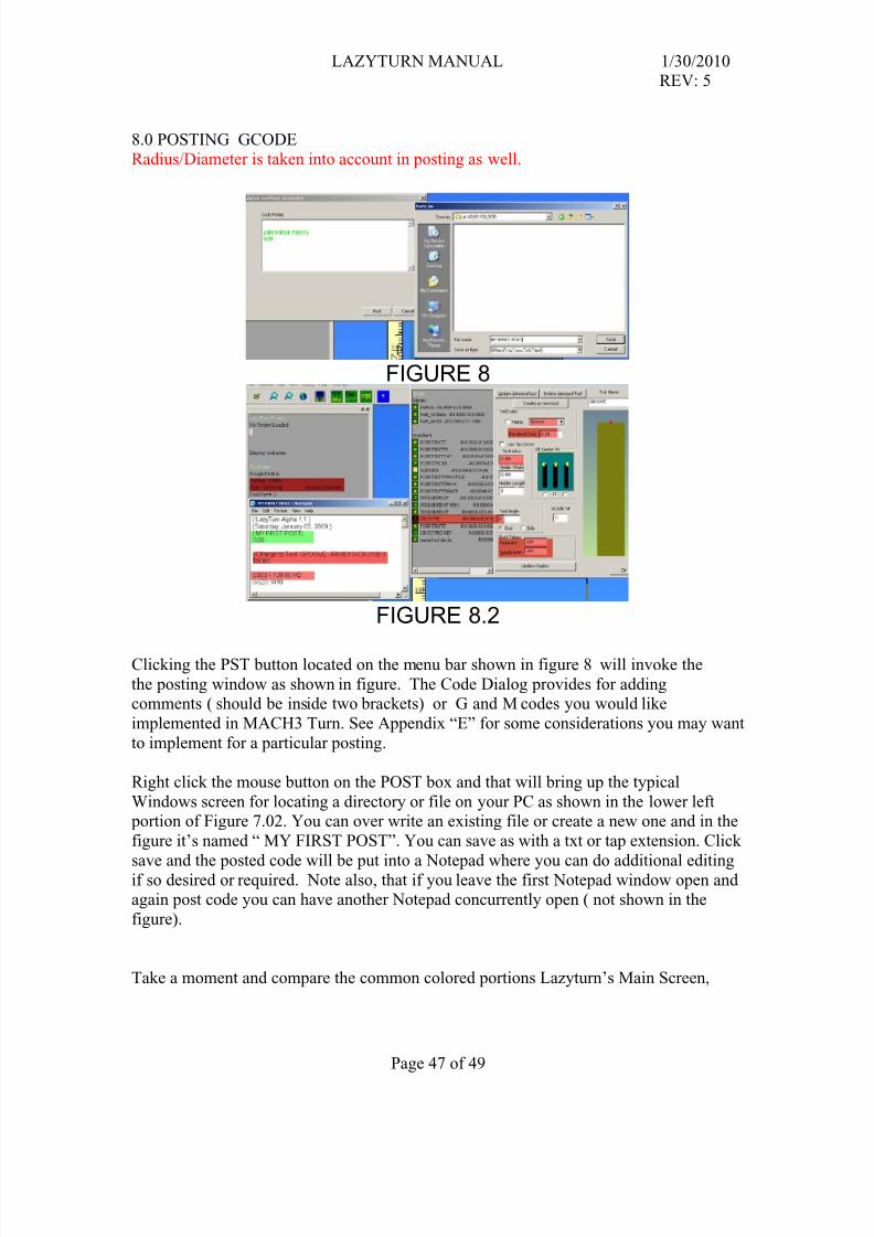
8.0 POSTING GCODERadius/Diameter is taken into account in posting as well.
FIGURE 8
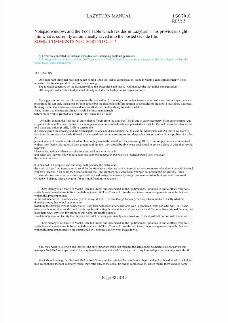
FIGURE 8.2
Clicking the PST button located on the menu bar shown in figure 8 will invoke the
the posting window as shown in figure. The Code Dialog provides for addingcomments ( should be inside two brackets) or G and M codes you would like
implemented in MACH3 Turn. See Appendix “E” for some considerations you may want
to implement for a particular posting.
Right click the mouse button on the POST box and that will bring up the typical
Windows screen for locating a directory or file on your PC as shown in the lower left portion of Figure 7.02. You can over write an existing file or create a new one and in the
figure it’s named “ MY FIRST POST”. You can save as with a txt or tap extension. Click
save and the posted code will be put into a Notepad where you can do additional editingif so desired or required. Note also, that if you leave the first Notepad window open andagain post code you can have another Notepad concurrently open ( not shown in the
figure).
Take a moment and compare the common colored portions Lazyturn’s Main Screen,
Notepad window, and the Tool Table which resides in Lazyturn. This providesinsight
into what is currently automatically saved into the posted GCode file.SOME COMMENTS NOT SORTED OUT !
3) Errors are generated for internal errors like self-interseting contours generated.4) Posting in Vista.. this can be done BUT take note that UAC in Vista may require you to put the file into a legal spot like the
folder LazyTurn is currently in.
TOOLPATHS
One important thing that must not be left behind is the tool radius compensation. Nobody wants a cam software that will not
reproduce the final object different from the drawing.
The toolpath generated by the lazyturn will be the exact piece and mach3 will manage the tool radius compensation
OR Lazyturn will create a toolpath that already includes the tooltip radius compensation ?
My suggestion is that mach3 compensates the tool radius. In this way a user is free to use its cam software. For example I made a
program to do just that, translate a dxf into gcode, but the final object differs because of the radius of the tools. I must draw it already
thinking on the tool and make some calculations that is difficult and easy to make mistakes.
Also, I think that this feature already should be functional in mach
before more work is pointed to a "turn utility", since it is a "must"
Actually, In turn, the final part is quite often different from the drawing. This is due to cutter geometry. Most cutters cannot cut
all parts without collisions. The true trick is to generate a compensated path, compensated not only for the tool radius, but also for the
tool shape and holder profile, AND to display thedifferences from the drawing and the finshed path, so one could use another tool to clear out what wasnt cut. All this of course will
take time. I currently have tools allowed to be created that mimic most inserts and shapes, but ground tools will be a problem for a bit.
At
present, one will have to create a tool as close as they can to the actual tool they are using, BUT, if one simply creates a button tool
with an inscribed circle radius of their ground tool tip, then they should be able to use such a tool to get very close to what their tryingto profile.
I have added radius vs diameter selections and well as metric vs inch
unit selection. I havent allowed for a realtime conversion between the two, so a loaded drawing uses whatever
the current units are.
It is planned that simple clicks and drags will generate the paths, and
the stock will go from transparent to solid for the simulations, then go back to transparent so you can see what doesnt cut with the toolyou have selected. You could then select another tool, and cut from only what hasnt yet been cut or redo the cut entirely. This
should allow you to get as close as possible to the drawing dimensions by using combinations of tools if you wish. ProposedGCode will display after generation for any modifications to be done.
There already is G41/G42 in Mach3Turn, but unless one understand all the tip directions, tip radius, X and Z offsets very well, (
and is brave) I woudlnt use it. Its a tough thing to use. SO LazyTurn will take the tool into account and generate code for that tool,
with radius precompensatedso the output code will produce exaclty what it says it will. It IS rare though for many turning jobs to produce exactly what the
drawing shows, due to tool geometry not
matching the drawing even if compensated. LazyTurn will show, after each tools path is generated, what parts did NOT cut, its up
tothe user then to select another tool that is capable of cutting the remaining stock, or accept the differences from original drawing. At
least thats how I envision it working at this point.. Im leading up to asimulation/generation facility that shows what didnt cut very prominantly and allows you to recut just that portion with a new tool.
There already is G41/G42 in Mach3Turn, but unless one understand all the tip directions, tip radius, X and Z offsets very well, (
and is brave) I woudlnt use it. Its a tough thing to use. SO LazyTurn will take the tool into account and generate code for that tool,with radius precompensated so the output code will produce exaclty what it says it will.
Yes, thats what Id use rigth and left for. The only important thing is it matches the actual tools boundries as close as you can
manage.( G41/G42 are implemented, but very hard to use and untested for a long time. LazyTrun will put out precompensated code.
Mach should manage the G41 and G42 by itself in my modest opinion The problem with g41 and g42 is they dont take the holder
into account, nor the tool geometry really, they refer only to the actual tip radius compensation, which makes them good on some
Collision detection is not possibel with g41/g42, since nothing is known about the tool other than the tip radius.. its more powerfull to
create the path precompensated, which si why most use precompensated code, not G41/G42 when they have a choice. End cut angles,
side cut angles, back angles.. none of them make a difference in G41/G42 so the cut is actually much harder to do using comp in a
controller , than from cam. The proof of that is simple, G41/G42 has been in turn for 3 years, no reports of problems, even though Iknow they exist. This means noone uses them even if available. Everyone I have done support for uses percompensated code.. i ts
always easier to do so..
I need to add a tool geometry collision adjuster to make the path right to the tool, at the moment the path is correct only to thetool's reported tool tip radius, and while the simulation is wrong since it doesnt take into account that radius in the 3d generations, the
path is correct and seems quite efficient for any radius tool held by a toolholder that wont collide with the object.
For those who do not get what is being shown here :-
What Art is trying to show is that the tool shape is being taken intoaccount when the profile of the part is roughed out, the unshaded parts are where the tool can not cut without gouging into the
finished part.If you look at the previous examples the tool could not have produced the shaded lines without the part being over cut in
certain areas, this was before the collision detection was working.
the whole shape of the tool is taken into account.
Not having done many DXF to Gcode conversions (read this as none) how would you know by downloading a DXF if your 3 axis
mill will be able to make it once Mach 3 has got hold of
the DXF and converted it? The Knight looks a little tricky with 3 axis.The knight would have to be 4 axis, either that or do one side and then
flip and do the other.
But if you add a 4th axis to the mill and use it as a spindle, mount a lathe tool in a clamp in the Z Axis and use it as an X axis and
use the X axis as a Z axis then you would use MachTurn and LazyTurn
Nice to see the undercut work, but Its a fluke of the algorithm I wrote. That'd be a tough cut ot be sure of as youd have to make surethat holder was weirdly enough shaped to allow for that cut.
The actual result you got is due to the fact I use only the actual tool
insert for collision detection, though I did intend to upgrade that some day to take the holder into account. ( which is why the hodler
size is specified, but unused at this point.
Lazyturn Idea Listing
1.Can we have the option of front or rear turret, better still a mixture of both. I have external tools on the front and internal tools on therear.
2. Can we have center line drilling and tapping with graphics, user to enter drill/tap dia and length etc.
3. Could we have a scaled plan view, backdrop of our lathe layout, that way collisions could be spotted (users could draw the planview as a dxf).
4. Would user defined tools be possible, tool and turret could then be drawn for above.5. Could you make it so that grooving/parting tools can have 2 offsets,
one on the front edge and one on the back edge of the tip. This is great for sizing grooves and maintaining position.
6. Is it possible to do X axis threading, e.g. lathe chuck scrolls.
7.A choice between radial and diametrical modes would certainly be a neat feature.8. Center line drilling and such should be do-able, certainly facing profiles will be on the Z face