LB-UA2324 - 24 Port UniPhyer LB-UA2348 - 48 Port UniPhyer LB-PA111 - PhyAdapter LB-PA110 - Extended Reach PhyAdapter Two wire Network Line Bridge Gateway System Description Part Number - 8003-02 Issue 3, May 2009
This document provides an overview on the UniPhyer LB-UA2348 and UniPhyer LB-UA2324 and the
LB-PA110 and LB-PA111 PhyAdapters. The LB-UA2324 is functionally the same as LB-UA2348 except
it only supports 24 ports and provides a different Power over Ethernet (POE) budget than the LB-UA-2348
UniPhyer. The LB-PA111 has Power Over Ethernet (POE) while the LB-PA110 does not. The document
contains:
� Descriptive material about the UniPhyer and PhyAdapter (chapter 1)
� Descriptive material about the software of the UniPhyer (chapter 2)
� Expansions of abbreviations used in the manual (Abbreviations)
Audience
The guide is intended for system engineers or operating personnel who want to have a basic understanding
of the UniPhyer.
Related Documentation
For information about installing, operating and maintaining, and troubleshooting the UniPhyer system, refer
to the UniPhyer Hardware Installation and User Guide.
For information about how to manage the UniPhyer through Web GUI, refer to the UniPhyer Web
Configuration Tool Guide.
Documentation Conventions
The following conventions are used in this manual to emphasize information that will be of interest to the
reader.
Danger — The described activity or situation might or will cause personal injury.
Warning — The described activity or situation might or will cause equipment damage.
Caution — The described activity or situation might or will cause service interruption.
Note — The information supplements the text or highlights important points.
2 / 32
———— System Description
1.1 General Overview of the UniPhyer LB-UA2348 and LB-UA2324
1.2 Technical Summary of the UniPhyer LB-UA2324 and LB-UA2348
1.3 Technical Summary of the PhyAdapter LB-PA110 and LB-PA111
1.4 Detailed Description of the UniPhyer LB-UA2348
1.5 General Overview
1.6 Configuration Management
1 — System Description
3 / 34
1.1 General Overview of the UniPhyer LB-UA2348 and LB-UA2324
The UniPhyer LB-UA2324 (24 port) and LB-UA2348 (48 Port) are Line Bridge Gateways within a
rack-mountable 2U high enclosure. The system provides up to 48 Line Bridge ports that when
connected to PhyAdapters can provide an IEEE 802.3af compliant 10/100 Mbps Power over Ethernet
(POE) port with broadband data rates using the two wire intra-office legacy wiring infrastructure. The
UniPhyer LB-UA2348 is capable of delivering very high speed data rates with up to ADSL2+
performance for each of the 48 ports, ideal for Voice over IP network deployments. With advanced
QoS features, the UniPhyer LB-UA2348 also has advanced Quality of Service (QoS) features to further
customize deployment to meet network needs.
The UniPhyer LB-UA2348 provides two uplink trunk ports with both electrical and optical Gigabit
Ethernet (GbE) interfaces..
The UniPhyer LB-UA2348 can act support of 802.3ad link aggression that extends the uplink
bandwidth to 2 Gbps and increases the reliability of uplink by line protection feature of 802.3ad. The
UniPhyer LB-UA2348 also supports stacking configuration that several UniPhyer LB-UA2348s can
stacked up to provide services to more subscribers for one GBE uplink.
Figure 1-1 shows the front panel view of the UniPhyer LB-UA2348.
Figure 0-1 UniPhyer LB-UA2348 Front Panel View
The LB-PA111 PhyAdapter is powered by the UniPhyer and provides IEEE 802.3af compliant 10/100
Mbit Power over Ethernet port. The LB-PA110 PhyAdapter is powered by the UniPhyer and provides
10/100 Mbit Ethernet port.
1— System Description
4 / 32
1.1.1 Features
� Highly compact solution that provides 24/48 Line Bridge ports in 2U space and stackable for higher
port density
� Provides power for both PhyAdapters and IP devices connected to PhyAdapters over two wire
twisted pair infrastructure on Line Interface.
� Equipped with fan, diagnostics and alarm reporting capability
� Remote configuration and software upgradeable
� Data signalling rates are up to ADSL2+ operation mode
� Wide operating temperature range from -10°C ~ 50°C (for UniPhyer).
� Provide two combo GBE trunk interfaces with both electrical (RJ-45) and fiber optical (SFP) ports
� Support Link Aggregation in IEEE 802.3ad that allows 2 GBE links to be aggregated together as a
logical link. Support both LACP protocol (dynamic) for load sharing and failover in case of loss of
Ethernet link
� User-friendly CLI, web-based GUI, and EMS (NMS) through in-band/out-band channels for
carrying out the OAM&P of the system
� Support system software download via FTP for both local and remote terminals
� Support database export and import functionality via TFTP for configuration backup and
restoration
� Support SNTP to automatically calibrate the time and date of the system
� Support on board thermal sensor to detect over temperature conditions with software configurable
thresholds that generate SNMP traps and syslog alarm entries
� Provide SSH (Secure Shell) for more secure remote operation
� Meet CE requirements
1 — System Description
5 / 34
1.1.2 System Application
Figure 0-2 UniPhyer LB-UA2348 system application
The UniPhyer LB-UA2348 leverages the redundant telephone cabling infrastructure to create a parallel
network with Power-over-Ethernet. This is a plug and play solution that can be deployed quickly and
easily with the default configuration.
The UniPhyer provides a permanent point-to-point link between the IP phone jack on the PhyAdapter
and the Phybridge UniPhyer and is thus able to guarantee predictable communication between the two
end points.
1— System Description
6 / 32
1.2 Technical Summary of the UniPhyer LB-UA2324 and LB-UA2348
1.2.1 Physical Specifications
Item Value
Width 431.8 mm (17 in.) not including the mounting brackets
Height 88.1 mm (3.47 in.) 2U
Depth 381 mm (15 in.)
Weight 5.36 Kg (11.8 pounds)
Rack Standard rack (19”)
1.2.2 Environmental Specifications
Item Value
Operating Temperature -10 ~ 50°C
Relative Humidity 10% to 95% (non-condensing) at 35°C
1.2.3 Power Specifications
Item Value
Power Supply Interface AC: 100 ~ 240V/50 ~ 60Hz.
Power Consumption: Full load maximum reach with PhyAdapters (no IP phones)
48 ports: 250 W per system
24 ports: 136 W per system
POE Budget POE budget includes line loss, maximum 10.6 W per port
POE Budget 48 port: 390 W
POE Budget 24 port: 255W
1 — System Description
7 / 34
1.3 Technical Summary of the PhyAdapter LB-PA110 an d LB-PA111
1.3.1 Physical Specifications
Item Value
Width 82.8 mm (3.26 in.)
Length 82.8 mm (3.26 in.)
Depth 27.2 (1.07 inch)
Weight 90 Grams (3.17 oz )
1.3.2 Environmental Specifications
Item Value
Operating Temperature 0 to 40°C
Relative Humidity 10% to 95% (non-condensing) at 35°C
1.3.3 Power Specifications
Item Value
Power Supply Interface Powered from the UniPhyer, 54 V DC maximum
Power Consumption: 2.5 W maximum (not including line or UniPhyer port power consumption which can add from 0.2 W to 0.7 W).
POE (LB-PA111 only) RJ45 port provides IEEE 802.3af compliant voltage on the non signaling pairs, 4-5 and 7-8.
POE Budget (LB-PA111 only) POE budget per PhyAdapter including line loss, is a maximum 10.6 W per RJ45 Ethernet port.
Class 1, 2 and some Class 3 IEEE 802.3af compliant devices are supported
1.3.4 Line Length Specifications
Item Value
Wire type Two wire twisted pair, 24 and 26 AWG
LB-PA111 – two wire Up to 1200 feet (with POE)
LB-PA110 – two wire Up to 3000 feet (no POE)
1— System Description
8 / 32
1.4 Detailed Description of the UniPhyer LB-UA2348
1.4.1 Module Functional Block Diagram
Figure 0-3 UniPhyer LB-UA2348 Module Functional B lock Diagram
The Power Management and PWS Module provide the power and signaling on the Line Ports for the PhyAdapters. The ADSL module aggregates 24/48 ports signaling traffic into the network processor card, the network processor terminates the ATM traffic into Ethernet packets through its SAR (Segmentation and Reassembly) function. The network processor also provides the Layer-2 Ethernet functions; it can support the mapping between the ATM VCI and VLAN ID (802.1q) and priority queues (802.1p). The mapping functionality between ATM PVC and VLAN ID include one PVC to one VLAN ID and multiple PVCs to one VLAN ID; all of which are configurable.
Through the two GBE uplink interfaces, the system can provide Link Aggregation (802.3ad), VLAN stacking, and Rapid Spanning Tree (802.1w) as ring protection architecture.
1 — System Description
9 / 34
1.4.2 UniPhyer and PhyAdapter Specifications
Description Specification
Trunk Interface Support both RJ45 and optical mini-GBIC (SFP) connectors for each uplink port (total 2 ports per box).
For electrical interface:
Support IEEE 802.3 10/100/1000 Base-T auto-sensing GBE. And the selection of speed for each port is independent.
Support auto-adaptive between full-duplex and half-duplex operation modes for 10 and 100 Mbps operation speed on a per trunk port basis. The system only supports full-duplex mode for 1000 Mbps.
For optical interface:
Support 1000 Base-TX/SX/LX/EX/ZX/LHX fiber interfaces (defined in IEEE 802.3z) depending on plug-in SFP transceiver
Support Ethernet frame that complies with IEEE 802.3z
Line Interface Each of the 24 or 48 ports are supplied power for the PhyAdapter and POE enabled device attached to PhyAdapter.
On the same port pair data signaling is provided by ADSL2+ operation that comply with G.992.5 Annex M (extended upstream bandwidth)
Supported signaling data rate:
- up to 25 Mbit/s downstream
- up to 1.4 Mbit/s upstream
Support rate adaptation modes defined in ITU-T G.992.5 and G.997.1 including Manual, Rate Adaptive At Init, and Dynamic Rate Adaptation modes
Support Seamless Rate Adaptation (SRA) to on-line reconfigure the total data rate according to the line condition
The subscriber interface is able to support Fast Channel or Interleaved Channel independently for each ADSL port.
Support loop diagnostic function specified in ITU-T G.992.5 for each ADSL port independently (support DELT loop diagnostics).
Supported PhyAdapters Each port on the Line Interface can be plugged into either LB-PA111 or LB-PA110 PhyAdapter models. The PhyAdapter is powered by the UniPhyer.
1— System Description
10 / 32
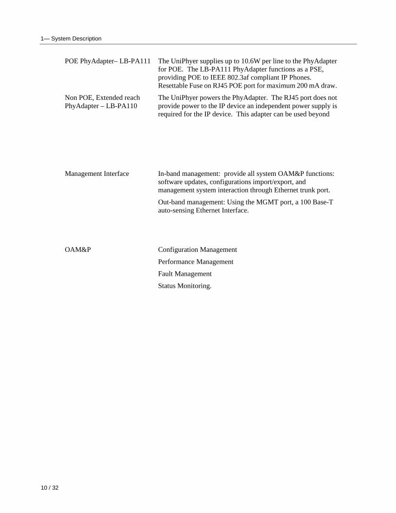
POE PhyAdapter– LB-PA111 The UniPhyer supplies up to 10.6W per line to the PhyAdapter for POE. The LB-PA111 PhyAdapter functions as a PSE, providing POE to IEEE 802.3af compliant IP Phones. Resettable Fuse on RJ45 POE port for maximum 200 mA draw.
Non POE, Extended reach PhyAdapter – LB-PA110
The UniPhyer powers the PhyAdapter. The RJ45 port does not provide power to the IP device an independent power supply is required for the IP device. This adapter can be used beyond
Management Interface In-band management: provide all system OAM&P functions: software updates, configurations import/export, and management system interaction through Ethernet trunk port.
Out-band management: Using the MGMT port, a 100 Base-T auto-sensing Ethernet Interface.
OAM&P Configuration Management
Performance Management
Fault Management
Status Monitoring.
1 — System Description
11 / 34
Ethernet/IP Functionality � General Bridging Function – Support IPv4 packet – Support IEEE802.1d Ethernet bridge function between
trunk Ether port and ATM VCs – Support Rapid Spanning Tree Protocol (RSTP) for the
trunk interfaces per IEEE 802.1w – Support static source MAC table provisioning,
automatic source MAC learning and block duplicate ones
– The system is able to maintain 4K entries in its own static MAC address table and to provision up to a maximum of 128 MAC entries per line port
� VLAN – Support IEEE 802.1q Port-based VLAN and
Protocol-based VLAN – Support 512 non-stacked VLAN-ID simultaneously
ranging from 1 to 4095 – Support VLAN stacking and VLAN cross-connect – Support IP Spoofing prevention – Support MAC anti-Spoofing – Support port isolation functionality. When port
isolation is enabled, no Layer-2 bridging between different ports (or subscriber lines) is supported in a VLAN
– Support static VLAN group and membership provisioning
� Multicast – Support IP multicast forwarding and the multicast
works well for RFC2684 bridged payload encapsulation mode
– Support up to 256 multicast groups and 256 copies simultaneously
– Support profile-based Multicast Access Control (up to 48 profiles) and assign any profile to a subscriber interface (the number of multicast channels within a profile is 256)
– Support to limit maximum number of IGMP groups joined per bridge port
– Support IGMP snooping/proxy per IGMP v1, v2, and v3
– Support selection between IGMP proxy and IGMP snooping
� ACL/Filtering – Support Layer-2 frame filtering based on
source/destination MAC addresses and EtherType – Support Layer-3 filtering based on IP header including
1— System Description
12 / 32
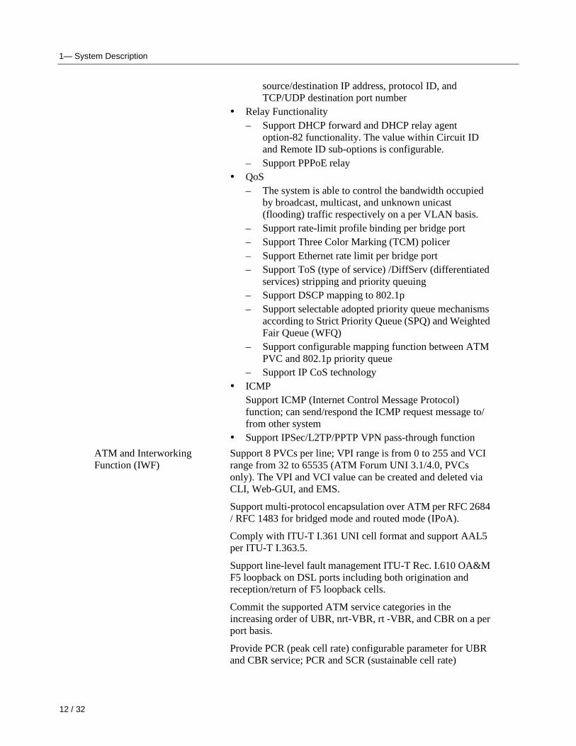
source/destination IP address, protocol ID, and TCP/UDP destination port number
� Relay Functionality – Support DHCP forward and DHCP relay agent
option-82 functionality. The value within Circuit ID and Remote ID sub-options is configurable.
– Support PPPoE relay � QoS
– The system is able to control the bandwidth occupied by broadcast, multicast, and unknown unicast (flooding) traffic respectively on a per VLAN basis.
– Support rate-limit profile binding per bridge port – Support Three Color Marking (TCM) policer – Support Ethernet rate limit per bridge port – Support ToS (type of service) /DiffServ (differentiated
services) stripping and priority queuing – Support DSCP mapping to 802.1p – Support selectable adopted priority queue mechanisms
according to Strict Priority Queue (SPQ) and Weighted Fair Queue (WFQ)
– Support configurable mapping function between ATM PVC and 802.1p priority queue
– Support IP CoS technology � ICMP
Support ICMP (Internet Control Message Protocol) function; can send/respond the ICMP request message to/ from other system
� Support IPSec/L2TP/PPTP VPN pass-through function
ATM and Interworking Function (IWF)
Support 8 PVCs per line; VPI range is from 0 to 255 and VCI range from 32 to 65535 (ATM Forum UNI 3.1/4.0, PVCs only). The VPI and VCI value can be created and deleted via CLI, Web-GUI, and EMS.
Support multi-protocol encapsulation over ATM per RFC 2684 / RFC 1483 for bridged mode and routed mode (IPoA).
Comply with ITU-T I.361 UNI cell format and support AAL5 per ITU-T I.363.5.
Support line-level fault management ITU-T Rec. I.610 OA&M F5 loopback on DSL ports including both origination and reception/return of F5 loopback cells.
Commit the supported ATM service categories in the increasing order of UBR, nrt-VBR, rt -VBR, and CBR on a per port basis.
Provide PCR (peak cell rate) configurable parameter for UBR and CBR service; PCR and SCR (sustainable cell rate)
1 — System Description
13 / 34
configurable parameters for rt-VBR and nrt-VBR.
Support upstream and downstream traffic shaping and policing on per PVC basis.
Support profile-based ATM traffic management (up to 252 profiles with one default and 251 user-configurable profiles) and the downstream/upstream ATM profile assignments are independent
Support PPPoE transparent forwarding and PPPoE intermediate agent
Support PPPoE/PPPoA interworking as defined in section 3.5.4 of TR-101.
1— System Description
14 / 32
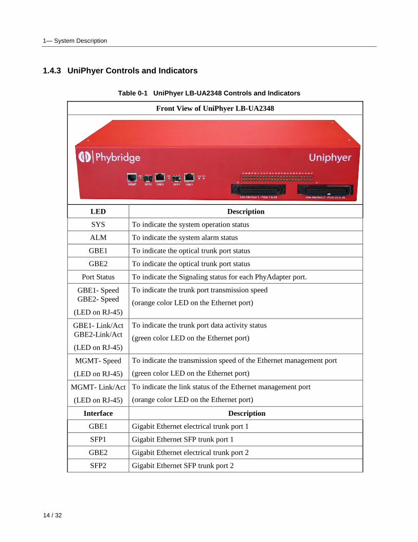
1.4.3 UniPhyer Controls and Indicators
Table 0-1 UniPhyer LB-UA2348 Controls and Indicat ors
Front View of UniPhyer LB-UA2348
LED Description
SYS To indicate the system operation status
ALM To indicate the system alarm status
GBE1 To indicate the optical trunk port status
GBE2 To indicate the optical trunk port status
Port Status To indicate the Signaling status for each PhyAdapter port.
GBE1- Speed GBE2- Speed
(LED on RJ-45)
To indicate the trunk port transmission speed
(orange color LED on the Ethernet port)
GBE1- Link/Act GBE2-Link/Act
(LED on RJ-45)
To indicate the trunk port data activity status
(green color LED on the Ethernet port)
MGMT- Speed
(LED on RJ-45)
To indicate the transmission speed of the Ethernet management port
(green color LED on the Ethernet port)
MGMT- Link/Act
(LED on RJ-45)
To indicate the link status of the Ethernet management port
(orange color LED on the Ethernet port)
Interface Description
GBE1 Gigabit Ethernet electrical trunk port 1
SFP1 Gigabit Ethernet SFP trunk port 1
GBE2 Gigabit Ethernet electrical trunk port 2
SFP2 Gigabit Ethernet SFP trunk port 2
1 — System Description
15 / 34
MGMT Ethernet Port connected to LAN for providing system out-band EMS/Telnet control interface, such as system monitor, control or software upgrade.
Line Interface One or two RJ-21 connector (50-pin dual row header) for connecting PhyAdapter lines.
Power Switch 0/1 (Off/On) located at rear of chassis by AC cord connection
1.4.4 Cooling System
The cooling system of the UniPhyer LB-UA2348 consists of two fans internal to chassis and additional
fan on the Internal Power Supply.
Features
� The two chassis fans will be turned on when system temperature is higher than T°C and will be
turned off when system temperature is less than T-10°C (the temperature threshold T can be
configured). Default value of T is -40 C.
1.4.5 Line Interface Port Power
The UniPhyer Line Bridge ports always have power enabled on all the ports (if DSL service is enabled
or not). The port provides 54 V DC supply to power the Adapter and provide the POE compliant IEEE
voltage to the RJ45 port on the PhyAdapter. The UniPhyer Line Interface port will not draw power
unless a PhyAdapter is plugged into the RJ11 terminated port pair.
1.4.6 Over Current protection
The UniPhyer Line Interface will shut off power to any port with a short or excessive current draw.
Always ensure proper wiring with no shorts on the wire line interface for your UniPhyer installation.
1.4.7 Twisted Pair Wiring Limitations
The UniPhyer System with the LB-PA111 PhyAdapter will support connections on 24 AWG and 26
AWG twisted pair wire up to 1200 feet. The 1200 feet length does not include the Ethernet cable length
connected to the PhyAdapter. Ethernet cable length can be up to 300 feet but this length as well can be
dependant on the distance of the PhyAdapter to the UniPhyer.
1— System Description
16 / 32
Note — Wiring gauge, wiring conditions, cross connections, and loop length all have an impact on the maximum reach and cconnection performance as well as supported Class of IP phone at PhyAdapter
Warning — The UniPhyer Line Interface and wiring is only for intra-office wiring, not for external to building wiring environments.
1-1.1.1 Extended reach with the LB-PA110 PhyAdapter
17 / 34
———— Software Introduction
2.1 General Overview
2.2 Configuration Management
2.3 Performance Management
2.4 Fault Management
2.5 Loopback Testing
2.6 Cluster Feature
2 — Software Introduction
18 / 34
1.5 General Overview
The software architecture of the UniPhyer LB-UA2348 is shown in the figure below. It can be
divided into three layers: the management layer, the OAM&P layer, and the firmware layer.
Figure 0-1 Management Software Model
As in the figure, CLI shell, SNMP agent, and WEB server are in the top-most layer (management
layer) of the system software and offering OAM&P function of the UniPhyer based on the
conceptual management features as follows:
� Configuration Management
� Performance Management
� Fault Management
The UniPhyer LB-UA2348 uses flash memory as the database (DB) to store system configuration
parameters, alarms and events. The firmware layer includes ADSL drivers, Memory and I/O control,
etc.
19 / 34
1.5.1 Features of Management Interface
� Support CLI, SNMP (v1, v2c), and web-based GUI management interface through both in-band
and out-band channels
� Support up to 10 CLI sessions at the same time
� The in-band management connection of the system is the highest priority of all supported
in-band traffic categories via the GBE trunk ports
� Support out-band management via:
- 10/100 base-T Ethernet via MGMT port
� Support Telnet interface for remote operators to login system operating console
� Support up to 32 configurable SNMP trap destinations and allow the SNMP traps to be sent to
any specified SNMP aware device, for instance, Network management center
2 — Software Introduction
20 / 34
1.6 Configuration Management
The configuration management contains the following aspects:
1. System Setup, such as setup for management IP address/net mask, GBE interface (including to
enable/disable and query the administrative/operational status of the trunk port), line port
(including to enable/disable/reset ADSL port, query the administrative/operational status of
the port, and bind profiles on a per port basis), CLI session and timeout, Cluster, SNTP, IP
routes, and user administration (including login authorization and provides three security
levels).
2. Bridge Configuration (see “Bridge Configuration” below for more description)
3. ADSL Configuration (see “ADSL Configuration” below for more description)
4. ATM traffic management
5. SNMP setup
The configuration management provides detecting and reporting to the operators through SNMP
Trap for all memory updates reflecting changes in the system configuration. It also provides
logging the changes in the operational state and making this information available (on-demand) to
the operators over the operation interface.
The system contains a database (DB) to store all the provisioning data so that the configuration can
be restored in re-booting. Authorized operators can query the DB to obtain configuration data.
Bridge Configuration
The bridge configuration of the UniPhyer LB-UA2348 includes the following aspects:
� Interface setup
� VLAN configuration: static VLAN, protocol based VLAN, VLAN translation, and IP/MAC
HistoryCollisions Monitoring tx single collision packets
HistoryTxBytes Monitoring tx bytes
HistoryTxPackets Monitoring tx packets
HistoryTxMulticast Monitoring tx multicast
HistoryTxBroadcast Monitoring tx broadcast
HistoryUtilization Monitoring tx Utilization
27 / 34
1.8 Fault Management
Fault management is conceptually partitioned into two levels: the system top level, and
interface-specific level. Both levels are alarm-level configurable and can be Major and Minor. All
the alarms are mask-able.
Fault management provides the alarm output through visible indicator (LED). The alarm/status
indications are automatically generated as a result of certain events/conditions. The UniPhyer
LB-UA2348 supports query of all current alarm status. It is also able to keep 256 records of
historical alarms and events respectively.
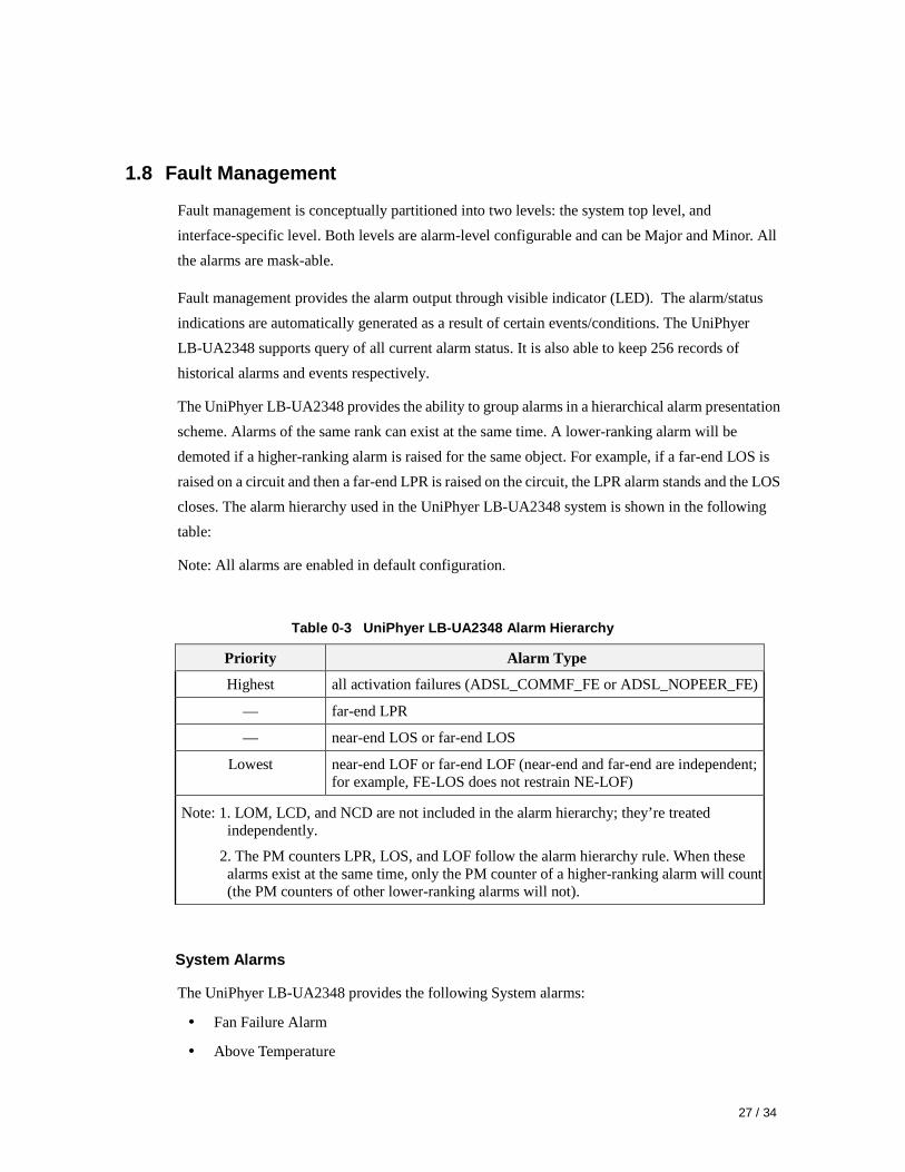
The UniPhyer LB-UA2348 provides the ability to group alarms in a hierarchical alarm presentation
scheme. Alarms of the same rank can exist at the same time. A lower-ranking alarm will be
demoted if a higher-ranking alarm is raised for the same object. For example, if a far-end LOS is
raised on a circuit and then a far-end LPR is raised on the circuit, the LPR alarm stands and the LOS
closes. The alarm hierarchy used in the UniPhyer LB-UA2348 system is shown in the following
table:
Note: All alarms are enabled in default configuration.
Table 0-3 UniPhyer LB-UA2348 Alarm Hierarchy
Priority Alarm Type
Highest all activation failures (ADSL_COMMF_FE or ADSL_NOPEER_FE)
— far-end LPR
— near-end LOS or far-end LOS
Lowest near-end LOF or far-end LOF (near-end and far-end are independent; for example, FE-LOS does not restrain NE-LOF)
Note: 1. LOM, LCD, and NCD are not included in the alarm hierarchy; they’re treated independently.
2. The PM counters LPR, LOS, and LOF follow the alarm hierarchy rule. When these alarms exist at the same time, only the PM counter of a higher-ranking alarm will count (the PM counters of other lower-ranking alarms will not).
System Alarms
The UniPhyer LB-UA2348 provides the following System alarms:
� Fan Failure Alarm
� Above Temperature
2 — Software Introduction
28 / 34
� Below Temperature
� Self-test Fail
� DSP Fail - you can see which DSP chip has failed from the user interface (Web GUI, CLI,
etc.). There is a number 1 ~ 4 in the alarm message/description corresponding to the DSP chip
1 ~ chip 4
GBE Alarms
The UniPhyer LB-UA2348 provides the following alarms for GBE interfaces:
� GBE1 SFP Loss of Signal
� GBE2 SFP Loss of Signal
ADSL Alarms
The UniPhyer LB-UA2348 provides the following ADSL alarms:
� LOS (Loss of Signal) -Near End/Far End
� LOF (Loss of Frame) -Near End/Far End
� LOM (Loss of Margin) -Near End/Far End
� LCD (Loss of Cell Delineation) -Near End/Far End
� NCD (No Cell Delineation) -Near End/Far End
� LOPWR (Loss of Power) -Far End
� COMMF: Unable to communicate with peer modem -Far End
� NOPEER: No peer present – Far End
29 / 34
1.9 Loopback Testing
The UniPhyer LB-UA2348 supports ATM and ADSL PhyAdapter loop diagnostics.
ATM :
The system provides F5 end-to-end or segment loopback.
ADSL:
The system provides Dual Ended Loop Testing (DELT), known as the PhyAdapter Lop Test, for
each ADSL line on a per port basis, according to the definition per section 8.12.3 of ITUT G992.3.
The following test parameters are supported:
- Channel Characteristics Function H(f) per subcarrier (CCF-ps),
- Quiet Line Noise PSD QLN(f) per subcarrier (QLN-ps),
- Signal-to-Noise Ratio SNR(f) per subcarrier (SNR-ps),
- Line Attenuation (LATN),
- Signal Attenuation (SATN),
- Signal-to-Noise Ratio Margin (SNRM),
- Attainable Net Data Rate (ATTNDR),
- Far-end Actual Aggregate Transmit Power (ACTATP),
- Near-End Actual Aggregate Transmit Power (ACTATP).
2 — Software Introduction
30 / 34
1.10 Cluster Feature
The UniPhyer LB-UA2348 supports Cluster feature that can make a group of NEs (network
elements) work together as a single NE from the management point of view. Operators can manage
the NEs in a cluster, called cluster nodes, via the same single IP address in terms of CLI, Web-based
GUI or SNMP based management interfaces. The UniPhyer LB-UA2348 currently provides cluster
feature that a cluster can include up to four cluster members (NEs). There are one Master and the
other members are all Slaves in a cluster. The Master works as a gateway of the Slaves, and it also
can forward CLI/Web/SNMP commands to the destination Slave. The Slaves can execute the
commands and respond to the Master.
There are two possible network topologies for conducting a Clustering Management group: Daisy
chain and Star.
Figure 0-2 Cluster network topology – Daisy Chain
31 / 34
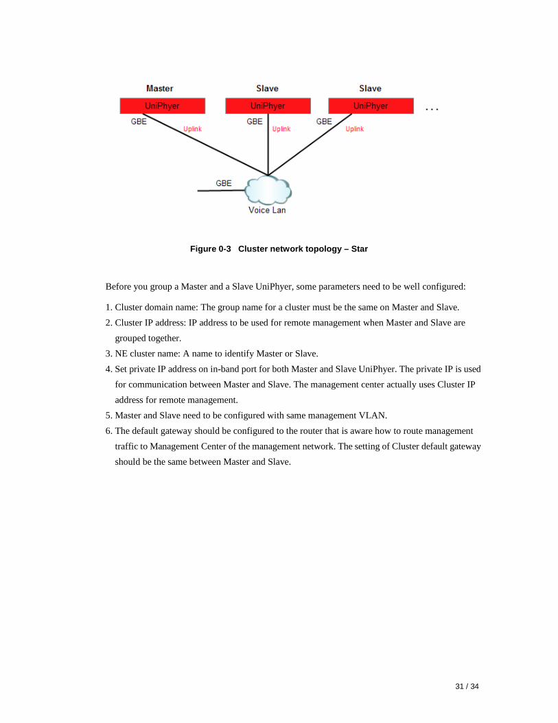
Figure 0-3 Cluster network topology – Star
Before you group a Master and a Slave UniPhyer, some parameters need to be well configured:
1. Cluster domain name: The group name for a cluster must be the same on Master and Slave.
2. Cluster IP address: IP address to be used for remote management when Master and Slave are
grouped together.
3. NE cluster name: A name to identify Master or Slave.
4. Set private IP address on in-band port for both Master and Slave UniPhyer. The private IP is used
for communication between Master and Slave. The management center actually uses Cluster IP
address for remote management.
5. Master and Slave need to be configured with same management VLAN.
6. The default gateway should be configured to the router that is aware how to route management
traffic to Management Center of the management network. The setting of Cluster default gateway
should be the same between Master and Slave.
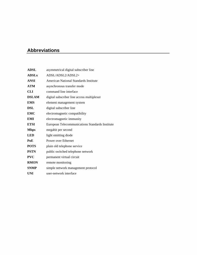
Abbreviations
ADSL asymmetrical digital subscriber line
ADSLx ADSL/ADSL2/ADSL2+
ANSI American National Standards Institute
ATM asynchronous transfer mode
CLI command line interface
DSLAM digital subscriber line access multiplexer
EMS element management system
DSL digital subscriber line
EMC electromagnetic compatibility
EMI electromagnetic immunity
ETSI European Telecommunications Standards Institute