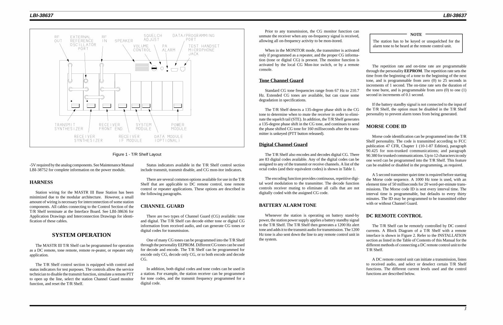
The MASTR III station control electronics are designed fordc/tone remote,remote/repeater, or repeater only applications. Thestation control electronics, also referred to as the Control Section,consists of a Backplane Board, Power Module, System Module,and an Interface Board. The backplane also connects the RFSection which consists of the Receiver Synthesizer Module, Re-ceiver Front End Module, Receiver IF Module, and the TransmitSynthesizer Module. The Control Section and the RF Sectioncombine into one assembly to form the T/R Shelf.
The Power Module, System Module, and the Interface Boardconnect to the backplane and thus to one another via 96 pinconnectors. The Control Section contains five backplane slotswith 3 presently unused. The Interface Board provides intercon-nection for a local microphone or handset, RS-232 programmingor diagnostics, transmitter PA control, transmitter PA fan, auxil-iary function relays, optional antenna switch, and optional circu-lator. Two connectors (terminal block and modular phone) areprovided for telephone line connections to the MASTR III Station.Additional connectors are provided on the backplane for connec-tion to GETCs used with systems such as EDACS, VOICEGUARD, GE-MARC, etc.
The Control Section uses programmable microcomputer tech-nology to control the base station’s transmitter, receiver, and audioprocessor. The System Module contains a Digital Signal Proces-sor (DSP) Module used for audio processing and tone generationand detection. The basic Control Section can provide one or twotransmit and receive frequencies in DC control applications, andup to four transmit and receive frequencies in tone control appli-cations. Options pro-vided by the Control Section include atransmitter drop-out delay (DOD) timer, Carrier Control Timer(CCT), Channel Guard, and Squelch Operated Relay output(SOR). Additional station options include:
• Battery alarm tone
• Type 90 or DTMF tone decoding
• 2/4 wire audio
• Morse code station identification
• Auxiliary control
BACKPLANE BOARD
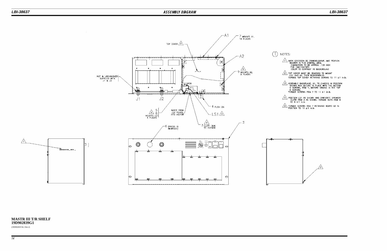
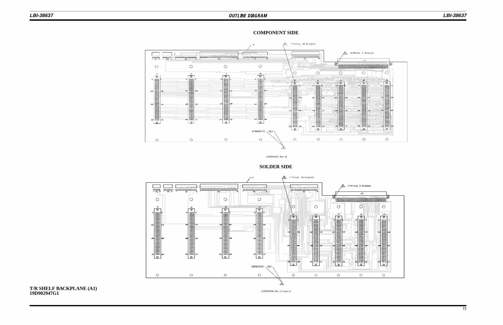
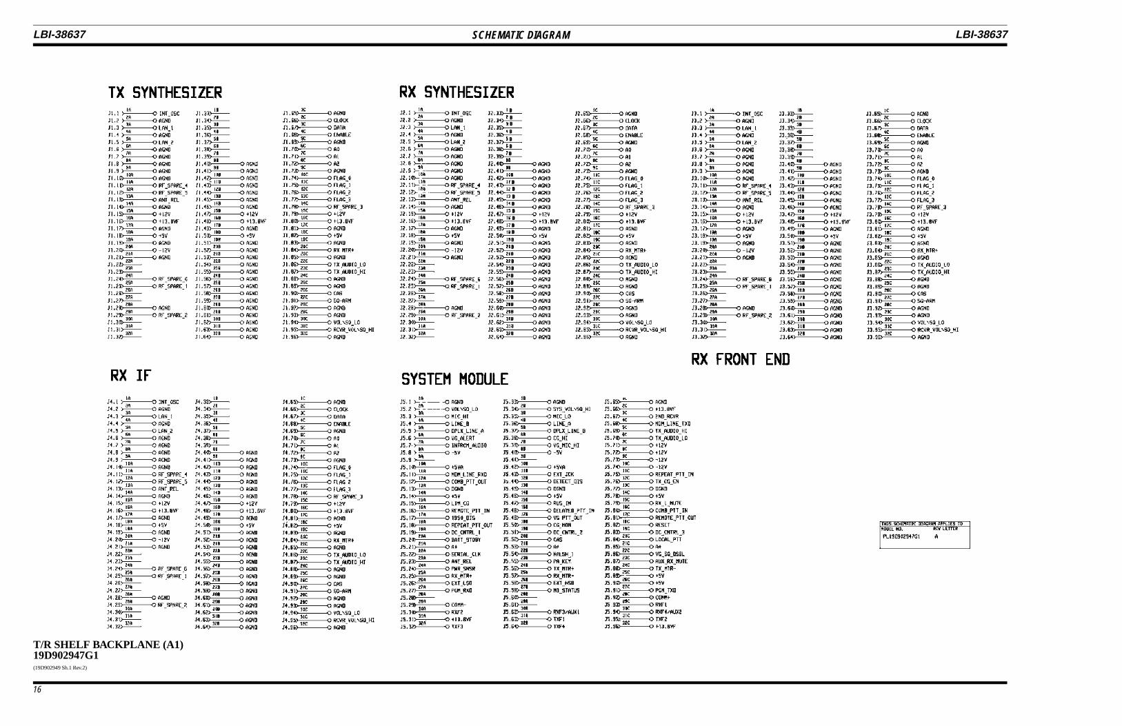
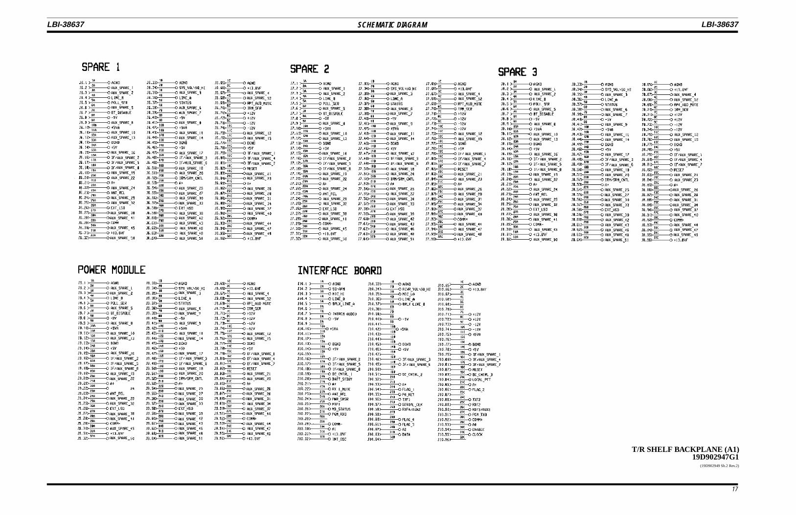
The Backplane Board (A1), 19D902947G1 (see AssemblyDiagram 19D902839 sheet 1), is a purely passive printed wiringboard (pwb) that mounts to the T/R shelf 19D902839G1. Thebackplane is functionally and physically segmented into twosections. When viewed from the front, the four slots to the leftconnect the RF Modules. The five slots on the right connect theControl Section modules. The horizontal slot above the five
Control Section slots is occupied by the Interface Board (A2). Theslots are assigned as follows from left to right (as viewed from thefront of the station):
• Transmitter Synthesizer Module (19D902780)
• Receiver Synthesizer Module (19D902781)
• Receiver Front End Module (19D902782)
• Receiver IF Module (19D902783)
• System Module (19D902590)
• Aux 1
• Aux 2
• Aux 3
• Power Module (19D902589)
INTERFACE BOARD
The Interface Board (A2), 19D902975G1 (see assembly Dia-gram 19D902839 sheet 1), mounts horizontally above the 5backplane slots of the Control Section. The Interface Boardprovides the following functions:
• Rx and Tx Synthesizer loading
• Telephone line interface with current level detection forremote control
• Audio PA for local speaker
• Transmitter power output level and control
• Manual adjustment with front panel access of receiversquelch and local speaker volume
• LED indication of PA Alarm
• Various connectors including RS232 programming portand Mic/Handset port.
SYSTEM MODULE
The System Module 19D902590G3 contains all audio proc-essing and control electronics. The System Module is equippedwith a DSP board that rides "piggyback" on the 19D903771G1System Board. Refer to Maintenance Manual LBI-38764 forcomplete information on the System Module.
POWER MODULE
The Power Module 19D902589G2 contains switching regu-lators for the +5V, +12V, and -12V DC supplies. The output of the+12V and -12V supplies are further regulated to provide +5V and
SPECIFICATIONS*
POWERInput Voltage 13.8 Vdc nominal (20%)Current Drain 4 Amperes maximum
AUDIO RESPONSEReceiver To Line +1, -3 dB from -6 dB per octave response for 300 to 3000 Hz referenced
to 1 kHz
Line to Transmitter +1, -3 dB from -6 dB per octave response for 300 to 3000 Hz referencedto 1 kHz
Receiver To Speaker +2, -8 dB from -6 dB per octave response for 300 to 3000 Hz referencedto 1 kHz
Line Output Level -19 dBm to +11 dBm
Line Input Level -19 dBm to +11 dBm
LINE LOOP IMPEDANCE 11K ohm maximum (8k ohm line, and 3K ohm matching)
LINE TERMINATING IMPEDANCE 600 ohms
NOTCH FILTER RESPONSE -45 dB @ 2175 Hz
CARRIER CONTROL TIMER Programmable from zero to 10 minutes
DROP-OUT DELAY TIMER Programmable from zero to l0 seconds
OPERATING TEMPERATURE -30° C to +60° C(-22° F to 140° F)
DISTORTION Less Than 2%
SERVICE SPEAKER 1 watt into 8 ohms
PANEL DIMENSIONS (H x W) 8.75 x 19.0 inches (5 Rack Units)
* These specifications are intended primarily for use by service personnel. Refer to the appropriate Specification Sheet forcomplete specifications.
LBI-38637 LBI-38637
2
-5V required by the analog components. See Maintenance ManualLBI-38752 for complete information on the power module.
HARNESS
Station wiring for the MASTR III Base Station has beenminimized due to the modular architecture. However, a smallamount of wiring is necessary for interconnection of some stationcomponents. All cables connecting to the Control Section of theT/R Shelf terminate at the Interface Board. See LBI-38636 forApplication Drawings and Interconnection Drawings for identi-fication of these cables.
SYSTEM OPERATION
The MASTR III T/R Shelf can be programmed for operationas a DC remote, tone remote, remote re-peater, or repeater onlyapplication.
The T/R Shelf control section is equipped with control andstatus indicators for test purposes. The controls allow the servicetechnician to disable the transmit function, simulate a remote PTTto open up the line, select the station Channel Guard monitorfunction, and reset the T/R Shelf.
Status indicators available in the T/R Shelf control sectioninclude transmit, transmit disable, and CG mon-itor indicators.
There are several common options available for use in the T/RShelf that are applicable to DC remote control, tone remotecontrol or repeater applications. These options are described inthe following paragraphs.
CHANNEL GUARD
There are two types of Channel Guard (CG) available: toneand digital. The T/R Shelf can decode either tone or digital CGinformation from received audio, and can generate CG tones ordigital codes for transmission.
One of many CG tones can be programmed into the T/R Shelfthrough the personality EEPROM. Different CG tones can be usedfor decode and encode. The T/R Shelf can be programmed forencode only CG, decode only CG, or to both encode and decodeCG.
In addition, both digital codes and tone codes can be used ina station. For example, the station receiver can be programmedfor tone codes, and the transmit frequency programmed for adigital code.
Prior to any transmission, the CG monitor function canunmute the receiver when any on-frequency signal is received,allowing all on-frequency activity to be mon-itored.
When in the MONITOR mode, the transmitter is activatedonly if programmed as a repeater, and the proper CG informa-tion (tone or digital CG) is present. The monitor function isactivated by the local CG Mon-itor switch, or by a remoteconsole.
Tone Channel Guard
Standard CG tone frequencies range from 67 Hz to 210.7Hz. Extended CG tones are available, but can cause somedegradation in specifications.
The T/R Shelf detects a 135-degree phase shift in the CGtone to determine when to mute the receiver in order to elimi-nate the squelch tail (STE). In addition, the T/R Shelf generatesa 135-degree phase shift in the CG tone, and continues to sendthe phase shifted CG tone for 160 milliseconds after the trans-mitter is unkeyed (PTT button released).
Digital Channel Guard
The T/R Shelf also encodes and decodes digital CG. Thereare 83 digital codes available. Any of the digital codes can beassigned to any of the transmit or receive channels. A list of theoctal codes (and their equivalent codes) is shown in Table 1.
The encoding function provides continuous, repetitive digi-tal word modulation to the transmitter. The decode functioncontrols receiver muting to eliminate all calls that are notdigitally coded with the assigned CG code.
BATTERY ALARM TONE
Whenever the station is operating on battery stand-bypower, the station power supply applies a battery standby signalto the T/R Shelf. The T/R Shelf then generates a 1200 Hz alerttone and adds it to the transmit audio for transmission. The 1200Hz tone is also sent down the line to any remote control unit inthe system.
The repetition rate and on-time rate are programmablethrough the personality EEPROM. The repetition rate sets thetime from the beginning of a tone to the beginning of the nexttone, and is programmable from zero (0) to 25 seconds inincrements of 1 second. The on-time rate sets the duration ofthe tone burst, and is programmable from zero (0) to one (1)second in increments of 0.1 second.
If the battery standby signal is not connected to the input ofthe T/R Shelf, the option must be disabled in the T/R Shelfpersonality to prevent alarm tones from being generated.
MORSE CODE ID
Morse code identification can be programmed into the T/RShelf personality. The code is transmitted according to FCCpublication 47 CFR, Chapter 1 (10-1-87 Edition), paragraph90.425 for non-trunked communications; and paragraph90.380 for trunked communications. Up to 12 characters in onlyone word can be programmed into the T/R Shelf. This featurecan be enabled or disabled in the programming, as required.
A 5 second transmitter quiet time is required before startingthe Morse code sequence. A 1000 Hz tone is used, with anelement time of 50 milliseconds for 20 word-per-minute trans-missions. The Morse code ID is sent every interval time. Theinterval time is programmable, but defaults to every thirtyminutes. The ID may be programmed to be transmitted eitherwith or without Channel Guard.
DC REMOTE CONTROL
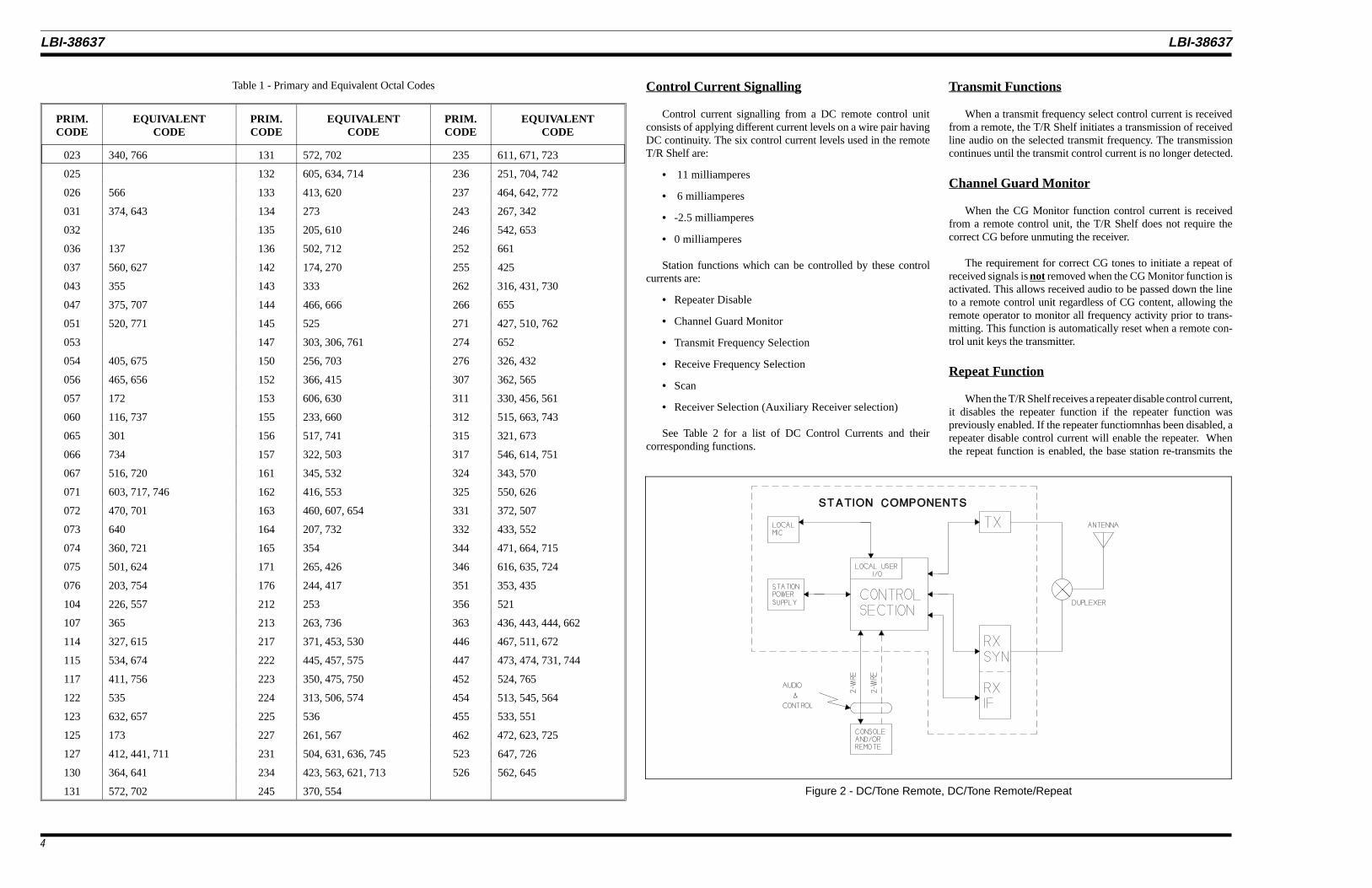
The T/R Shelf can be remotely controlled by DC controlcurrents. A Block Diagram of a T/R Shelf with a remoteinterface is shown in Figure 2. Refer to the INSTALLATIONsection as listed in the Table of Contents of this Manual for thedifferent methods of connecting a DC remote control unit to theT/R Shelf.
A DC remote control unit can initiate a transmission, listento received audio, and select or deselect certain T/R Shelffunctions. The different current levels used and the controlfunctions are described below.
Figure 1 - T/R Shelf Layout
The station has to be keyed or unsquelched for thealarm tone to be heard at the remote control unit.
NOTE
LBI-38637 LBI-38637
3
Control Current Signalling
Control current signalling from a DC remote control unitconsists of applying different current levels on a wire pair havingDC continuity. The six control current levels used in the remoteT/R Shelf are:
• 11 milliamperes
• 6 milliamperes
• -2.5 milliamperes
• 0 milliamperes
Station functions which can be controlled by these controlcurrents are:
See Table 2 for a list of DC Control Currents and theircorresponding functions.
Transmit Functions
When a transmit frequency select control current is receivedfrom a remote, the T/R Shelf initiates a transmission of receivedline audio on the selected transmit frequency. The transmissioncontinues until the transmit control current is no longer detected.
Channel Guard Monitor
When the CG Monitor function control current is receivedfrom a remote control unit, the T/R Shelf does not require thecorrect CG before unmuting the receiver.
The requirement for correct CG tones to initiate a repeat ofreceived signals is not removed when the CG Monitor function isactivated. This allows received audio to be passed down the lineto a remote control unit regardless of CG content, allowing theremote operator to monitor all frequency activity prior to trans-mitting. This function is automatically reset when a remote con-trol unit keys the transmitter.
Repeat Function
When the T/R Shelf receives a repeater disable control current,it disables the repeater function if the repeater function waspreviously enabled. If the repeater functiomnhas been disabled, arepeater disable control current will enable the repeater. Whenthe repeat function is enabled, the base station re-transmits the
received (incoming) signal when a valid CG tone or code ispresent. When the repeat function is disabled, the T/R Shelf doesnot initiate transmission of received signals.
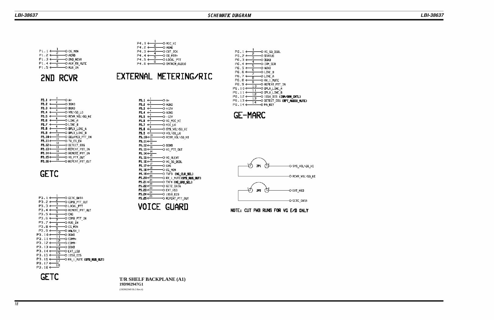
Auxiliary Receiver
With an auxiliary receiver connected to the T/R Shelf usingwiring harness 19B802398P1, audio from this auxiliary (second)receiver may be routed to the telephone line connecting a remotecontrol unit. A separate 600 ohm balanced output is also providedby the second receiver for applications requiring audio at a secondremote location.
A remote control unit may apply DC control currents to selectwhich receiver audio is heard at the remote as listed below:
1. Main receiver audio only,
2. Auxiliary receiver audio only, or
3. Both main receiver and auxiliary receiver audio.
For Channel Guard applications, CG Monitor monitors thetraffic on the auxiliary receiver frequency and the main receiverfrequency.
TONE REMOTE CONTROL
In tone remote applications, the T/R Shelf uses its DigitalSignal Processor (DSP) to interface with a tone remote controlunit through a two- or four-wire phone line. A Block Diagram ofthe T/R Shelf remote interface is shown in Figure 2.
A tone remote control unit can initiate a transmission, listento received audio, and select or deselect T/R Shelf functions.Functions selected by the different available tones can be pro-grammed so that a 1450 Hz "Function" tone, for example, can beused for different functions in different control shelves.
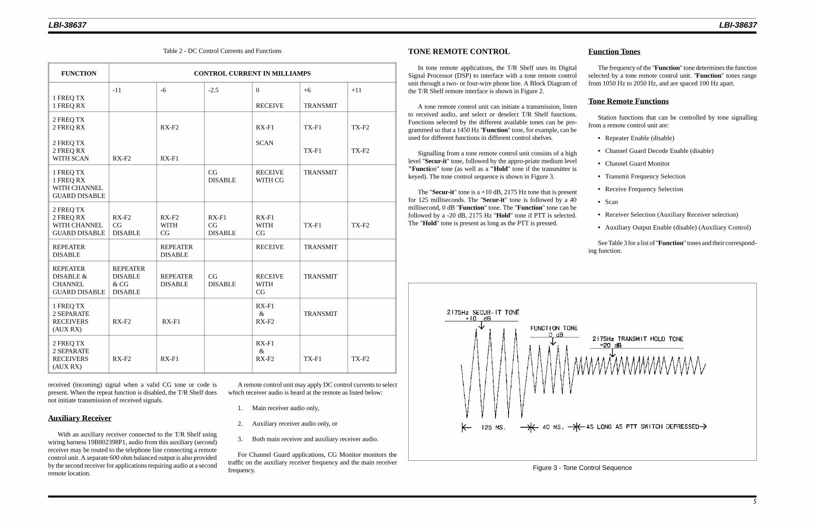
Signalling from a tone remote control unit consists of a highlevel "Secur-it" tone, followed by the appro-priate medium level"Functi on" tone (as well as a "Hold " tone if the transmitter iskeyed). The tone control sequence is shown in Figure 3.
The "Secur-it" tone is a +10 dB, 2175 Hz tone that is presentfor 125 milliseconds. The "Secur-it" tone is followed by a 40millisecond, 0 dB "Function" tone. The "Function" tone can befollowed by a -20 dB, 2175 Hz "Hold" tone if PTT is selected.The "Hold" tone is present as long as the PTT is pressed.
Function Tones
The frequency of the "Function" tone determines the functionselected by a tone remote control unit. "Function" tones rangefrom 1050 Hz to 2050 Hz, and are spaced 100 Hz apart.
Tone Remote Functions
Station functions that can be controlled by tone signallingfrom a remote control unit are:
See Table 3 for a list of "Function" tones and their correspond-ing function.
Table 2 - DC Control Currents and Functions
FUNCTION CONTROL CURRENT IN MILLIAMPS
1 FREQ TX1 FREQ RX
-11 -6 -2.5 0
RECEIVE
+6
TRANSMIT
+11
2 FREQ TX2 FREQ RX
2 FREQ TX2 FREQ RXWITH SCAN RX-F2
RX-F2
RX-F1
RX-F1
SCAN
TX-F1
TX-F1
TX-F2
TX-F2
1 FREQ TX1 FREQ RXWITH CHANNELGUARD DISABLE
CGDISABLE
RECEIVEWITH CG
TRANSMIT
2 FREQ TX2 FREQ RXWITH CHANNELGUARD DISABLE
RX-F2CGDISABLE
RX-F2WITHCG
RX-F1CGDISABLE
RX-F1WITHCG
TX-F1 TX-F2
REPEATERDISABLE
REPEATERDISABLE
RECEIVE TRANSMIT
REPEATERDISABLE &CHANNELGUARD DISABLE
REPEATERDISABLE& CGDISABLE
REPEATERDISABLE
CGDISABLE
RECEIVEWITHCG
TRANSMIT
1 FREQ TX2 SEPARATERECEIVERS(AUX RX)
RX-F2 RX-F1
RX-F1 &RX-F2
TRANSMIT
2 FREQ TX2 SEPARATERECEIVERS(AUX RX)
RX-F2 RX-F1
RX-F1 &RX-F2 TX-F1 TX-F2
Figure 3 - Tone Control Sequence
LBI-38637 LBI-38637
5
Table 3 - Tone Control Function and Frequency
FUNCTION TONE
RX Channel Guard Disable (Reset by PTT) 2050 Hz
TX-Freq. No. 1 1950 Hz
TX-Freq. No. 2 1850 Hz
TX-Freq. No. 1 or Receiver No. 1 1750 Hz
TX-Freq. No. 2 or Receiver No. 2 1650 Hz
Channel Guard Decode On or RepeaterEnable*
1550 Hz
Channel Guard Decode Off or RepeaterDisable*
1450 Hz
TX-Freq. No. 3 or Aux. Function 1 On 1350 Hz
TX-Freq. No. 4 or Aux. Function 1 Off 1250 Hz
Repeater Enable* 1150 Hz
Repeater Disable* or Scan or SimultaneousMonitor
1050 Hz
* Repeater Enable (disable) is 1150/1050 only whenChannel Guard On/Off is present.
Repeat Enable (disable)
When a repeater enable (disable) "Function" tone is receivedon the line from a remote, the T/R Shelf enables (disables) therepeater function. When the repeat function is disabled, the T/RShelf will not initiate a re-transmission of received signals. How-ever, the audio is still routed to the remote control unit if thetransmitter is not keyed.
Channel Guard Monitor
When a CG Monitor "Function" tone is received from aremote control unit, received audio is sent down the line to aremote control unit and the local speaker regardless of CG content.This allows the operator to monitor all frequency activity prior totransmitting. The requirement for a correct CG tone or code toinitiate a repeat of received signals is NOT removed.
The monitor function is disabled when a remote control unitkeys the transmitter.
Channel Guard Enable (disable)
This function is the same as CG Monitor except that theMonitor function is not deselected by a remote PTT. The Monitorfunction is deselected only by a CG enable "Function" tone.
One-Four Frequencies
The T/R shelf receives "Function" tones to select one of fourchannels (frequencies). The Control Section then loads the Tx andRx synthesizers with a 32 bit serial word that contains the appro-priate frequency information.
Transmit Functions
When a transmit frequency select "Function" tone is receivedfrom a remote, the T/R Shelf filters out the "Hold" tone andinitiates a transmission of received line audio. The transmissioncontinues until the "Hold" tone is no longer detected.
Intercom Function
The T/R Shelf intercom function allows a service technicianat the station to communicate with a remote control unit withoutkeying the transmitter.
When no valid signal is present, the T/R Shelf routes the lineaudio to the local speaker. A remote control unit can then selectthe intercom function and send audio (no control tones) over theline. This remote audio will be heard only at the station speaker,and will not be transmitted.
The service technician can communicate with the remotecontrol unit by placing the T/R Shelf transmit disable switch inthe disable position. The local microphone at the station can thenbe keyed and audio sent only down the remote lines to the remotecontrol unit. This audio is not transmitted by the station.
While in the intercom mode, receiver audio will continue tohave priority over line audio to the local speaker, and local(station) mic audio will have priority over receiver audio to theremote line.
Auxiliary Receiver
A remote control unit can control the state of the RX 2 MUTEoutput line using "Function" tones. The "Function" tones allowthe T/R Shelf to send the main receiver audio only, the auxiliaryreceiver audio only, or both the main receiver and auxiliaryreceiver audio output to a remote control unit.
Scan Function
The scan function allows the user to scan multiple frequenciesusing the station receiver.
When no signal is being received on any channel, the scanfunction sequentially selects and monitors each channel. If asignal is detected, the T/R Shelf locks onto the channel for theduration of the message and discontinues scanning. The defaultsample time for each channel is 80 milliseconds. A channel withthe receiver unsquelched will be locked on.
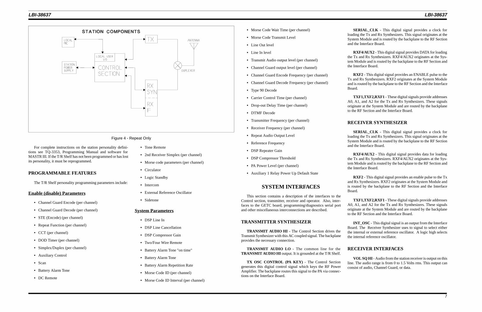
REPEAT FUNCTION
The T/R Shelf performs a basic repeat function in whichreceived signals are re-transmitted after filtering and level adjust-ments. Figure 4 is a block diagram of the T/R Shelf interface in arepeat only system.
Received signals are applied to the VOL/SQ HI line from thereceiver, and are routed to the transmitter on the TX AUDIO OUTline for re-transmission. If Channel Guard is present, the receivedChannel Guard information is filtered out and the transmit Chan-nel Guard , if enabled, is encoded and summed with receivedaudio and then re-transmitted.
Some repeater stations have timing restraints mandated by theFCC. Two timing circuits are available for use in these applica-tions. The timing circuits are a Carrier Control Timer (CCT), anda Drop-out Delay Timer (DOD).
Carrier Control Timer
The Carrier Control Timer (CCT) limits the time the stationtransmitter remains keyed for a single transmission. The time limitcan be preprogrammed from zero (0) seconds to 600 seconds (10minutes) in one-second steps. All control shelves equipped withthe CCT are shipped with the timer programmed for three min-utes.
The timing cycle begins when the transmitter is keyed bypressing the PTT button on the local microphone, or the PTTbutton of a remote or mobile radio generating the signal, activatingthe repeater. If the station is equipped with Channel Guard, theremote signal must contain the proper Channel Guard tone. Tim-ing ends and the timer is reset when the transmitter is unkeyed.
If the timing limit is exceeded, the T/R Shelf will turn off thetransmitter through the ANT RELAY and TX OSC CONTROLoutputs. The Carrier Control Timer function is reset whenever aPTT switch is released, whether it is at the remote control unit orother keying source.
Whenever the timing cycle is exceeded by a repeat PTT, thestations will not activate another repeat until the PTT is releasedfrom any source. However, the T/R Shelf will re-transmit fromanother source (such as a remote control unit) whenever the timelimit has expired on a repeat PTT.
Drop-Out Delay Timer
In repeater applications, the Drop-Out Delay Timer (DOD) isdesigned to decrease the number of transmitter on/off cycles. Thisis achieved by keeping the transmitter keyed for a predeterminedperiod after a repeat transmission has ended. This period can beprogrammed for zero (0) to ten (10) seconds in 100-millisecond(0.1 second) steps. All stations equipped with the DOD areshipped from the factory with the timer set for three seconds.
The timer starts whenever a repeat transmission ends. Thetransmitter is not de-energized through the TX OSC CONTROLand ANT RELAY outputs until the timer runs out.
If a new transmission is initiated before the timer runs out, thetransmitter remains energized and the new transmission com-pleted. If no new transmission is initiated, the transmitter willremain on until the DOD times out.
PROGRAMMING
All input and output levels to/from the Control Section areadjusted by electronic potentiometers. These potentiometers areadjusted by the Utility Handset SPK9024 connected to theMic/Handset port or by a personal computer (PC) connected tothe Programming/Diagnostic port, both accessible from the frontof the T/R shelf.
The T/R shelf contains an Electrically Erasable ProgrammableRead Only Memory (EEPROM) whose contents define the per-sonality of the station. The contents of this EEPROM may onlybe modified through the handset or by running the appropriatesoftware and a PC connected to the programming port.
Timing restraints apply to local and remote transmissionsas well as the repeat function. Local, remote, and repeatPTT timers are each programmed separately and are com-pletely independent timers.
NOTE
The Drop-Out Delay Timer is used primarily for re-peater functions. Other transmissions, including thoseoriginating from the local microphone, typically do notuse a DOD timer.
NOTE
LBI-38637 LBI-38637
6
For complete instructions on the station personality defini-tions see TQ-3353, Programming Manual and software forMASTR III. If the T/R Shelf has not been programmed or has lostits personality, it must be reprogrammed.
PROGRAMMABLE FEATURES
The T/R Shelf personality programming parameters include:
Enable (disable) Parameters
• Channel Guard Encode (per channel)
• Channel Guard Decode (per channel)
• STE (Encode) (per channel)
• Repeat Function (per channel)
• CCT (per channel)
• DOD Timer (per channel)
• Simplex/Duplex (per channel)
• Auxiliary Control
• Scan
• Battery Alarm Tone
• DC Remote
• Tone Remote
• 2nd Receiver Simplex (per channel)
• Morse code parameters (per channel)
• Circulator
• Logic Standby
• Intercom
• External Reference Oscillator
• Sidetone
System Parameters
• DSP Line In
• DSP Line Cancellation
• DSP Compressor Gain
• Two/Four Wire Remote
• Battery Alarm Tone "on time"
• Battery Alarm Tone
• Battery Alarm Repetition Rate
• Morse Code ID (per channel)
• Morse Code ID Interval (per channel)
• Morse Code Wait Time (per channel)
• Morse Code Transmit Level
• Line Out level
• Line In level
• Transmit Audio output level (per channel)
• Channel Guard output level (per channel)
• Channel Guard Encode Frequency (per channel)
• Channel Guard Decode Frequency (per channel)
• Type 90 Decode
• Carrier Control Time (per channel)
• Drop-out Delay Time (per channel)
• DTMF Decode
• Transmitter Frequency (per channel)
• Receiver Frequency (per channel)
• Repeat Audio Output Level
• Reference Frequency
• DSP Repeater Gain
• DSP Compressor Threshold
• PA Power Level (per channel)
• Auxiliary 1 Relay Power Up Default State
SYSTEM INTERFACES
This section contains a description of the interfaces to theControl section, transmitter, receiver and operator. Also, inter-faces to the GETC board, programming/diagnostics serial portand other miscellaneous interconnections are described.
TRANSMITTER SYNTHESIZER
TRANSMIT AUDIO HI - The Control Section drives theTransmit Synthesizer with this AC coupled signal. The backplaneprovides the necessary connection.
TRANSMIT AUDIO LO - The common line for theTRANSMIT AUDIO HI output. It is grounded at the T/R Shelf.
TX OSC CONTROL (PA KEY) - The Control Sectiongenerates this digital control signal which keys the RF PowerAmplifier. The backplane routes this signal to the PA via connec-tions on the Interface Board.
SERIAL_CLK - This digital signal provides a clock forloading the Tx and Rx Synthesizers. This signal originates at theSystem Module and is routed by the backplane to the RF Sectionand the Interface Board.
RXF4/AUX2 - This digital signal provides DATA for loadingthe Tx and Rx Synthesizers. RXF4/AUX2 originates at the Sys-tem Module and is routed by the backplane to the RF Section andthe Interface Board.
RXF2 - This digital signal provides an ENABLE pulse to theTx and Rx Synthesizers. RXF2 originates at the System Moduleand is routed by the backplane to the RF Section and the InterfaceBoard.
TXF1,TXF2,RXF1 - These digital signals provide addressesA0, A1, and A2 for the Tx and Rx Synthesizers. These signalsoriginate at the System Module and are routed by the backplaneto the RF Section and the Interface Board.
RECEIVER SYNTHESIZER
SERIAL_CLK - This digital signal provides a clock forloading the Tx and Rx Synthesizers. This signal originates at theSystem Module and is routed by the backplane to the RF Sectionand the Interface Board.
RXF4/AUX2 - This digital signal provides data for loadingthe Tx and Rx Synthesizers. RXF4/AUX2 originates at the Sys-tem Module and is routed by the backplane to the RF Section andthe Interface Board.
RXF2 - This digital signal provides an enable pulse to the Txand Rx Synthesizers. RXF2 originates at the System Module andis routed by the backplane to the RF Section and the InterfaceBoard.
TXF1,TXF2,RXF1 - These digital signals provide addressesA0, A1, and A2 for the Tx and Rx Synthesizers. These signalsoriginate at the System Module and are routed by the backplaneto the RF Section and the Interface Board.
INT_OSC - This digital signal is an output from the InterfaceBoard. The Receiver Synthesizer uses to signal to select eitherthe internal or external reference oscillator. A logic high selectsthe internal reference oscillator.
RECEIVER INTERFACES
VOL SQ HI - Audio from the station receiver is output on thisline. The audio range is from 0 to 1.5 Volts rms. This output canconsist of audio, Channel Guard, or data.
Figure 4 - Repeat Only
LBI-38637 LBI-38637
7
VOL SQ LO - This is the common line for the VOL SQ HIinput. It is grounded in the T/R Shelf.
CAS (Carrier Activity Sensor) - A TTL high on this inputindicates an on-frequency signal is being received. A TTL low onthis input indicates an on-frequency signal is not being received.This input is independent of the presence of a proper CG tone.
RX 1 MUTE - The T/R Shelf presents a low (≤ 0.3 Vdc @ ≤30 milliamperes) on this open collector output when the audiofrom receiver one is muted.
AUX RX MUTE - The T/R Shelf presents a low (≤ 0.3 Vdc@ ≤ 30 milliamperes) on this open collector output when the audiofrom receiver two is muted. This output is only used when anauxiliary receiver is connected to the T/R Shelf through theSECOND RCVR input.
INTERCOM AUDIO - If an on-frequency signal is present,and the receiver is not muted (RX 1 MUTE = open collector),de-emphasized audio with no CG present is routed to this output.
If the receiver is muted, the local microphone not keyed, andno RF signal, "Secur-it" tone or "Function" tone is present, audioreceived from the line is routed to the INTERCOM AUDIOoutput.
RUS IN - This RUS output from the second receiver indicatesto the T/R shelf that the second receiver is unsquelched with theproper channel guard.
CG MON - This output from the T/R shelf to the secondreceiver causes the second receiver to drive its’ audio outputwhenever it receives an on-frequency signal of sufficient strengthto unsquelch the receiver (RUS is active).
2ND RCVR - This T/R shelf input is driven by the secondreceiver’s line driver monitor output. Using this output instead ofthe balanced 600 ohm output allows the audio from the secondreceiver to drive both the remote line pair in addition to a seperateline pair at another remote site.
GETC INTERFACES
RCVR VOL/SQ HI - Receiver audio is routed to the GETCfor recovery of 9600 bps digital data and recovery of 150 bpssubaudible signalling data.
LINE A, LINE B - This 600 ohm balanced pair from theGETC connects to the T/R Shelf transmit pair telephone line. Thisprovides a 9600 bps downlink from the GETC to a second remoteGETC.
DPLX LINE A, DPLX LINE B - This 600 ohm balancedpair to the GETC connects to the T/R Shelf receive pair telephoneline. This provides a 9600 bps uplink from a remote GETC to thestation’s GETC.
DELAYED PTT IN - When active this GETC output keysthe station’s transmitter.
TX CG EN - This GETC output is only used in Voice GuardEnd-to-End stations. When a guarded transmission is done, theGETC pulses the 1950 DIS line. The station then mutes the 1950Hz voting tone. The GETC should then activate the TX CG ENline. If it does not activate it within a second of pulsing the 1950DIS, the voting tone will come back on.
DETECT DIS - This T/R Shelf input from the GETC signalsthe T/R shelf whether receive audio or high speed data should betransmitted.
REPEAT PTT IN - This GETC output causes the station toperform a RUS PTT in Voice Guard and is used in back-to-backrepeater applications to key the transmitter.
VG PTT IN - This open collector output from the T/R shelfis not used.
REPEAT PTT OUT - This T/R shelf output is true when thestation is repeating or doing a guarded remote PTT in Voice GuardEnd-to-End.
GETC DATA - This T/R shelf input from the GETC providesa path to the transmitter for high speed data transmission.
COMB PTT OUT - This T/R shelf output signals to theGETC that the transmitter is keyed by any PTT except for MorseCode.
LOCAL PTT - This signal is an input to the T/R shelf andthe GETC that indicates that PTT on the local mic port is true.
REMOTE PTT OUT - This T/R shelf output is true when aremote PTT function is being executed. However, turning on theREM PTT switch on the front of the System Module will notactivate this output.
CAS - This T/R shelf output is driven true when the receiveris unsquelched.
COMB PTT IN - This T/R shelf input is currently not used.
RUS IN - This T/R shelf input is driven true by the GETC’sRUS OUT or by an auxiliary receiver when it becomes unsquel-ched.
CG MONITOR - This T/R shelf output signals to the GETCthat the station is operating in Channel Guard Monitor state.
EXT LSD - This T/R shelf input provides a path forsubaudible signalling data from the GETC to the transmitter.
1950 DIS - This T/R shelf input from the GETC signals theT/R shelf to mute the 1950 Hz voting tone in Voice GuardEnd-to-End applications. In Voice Guard Encrypt/Decrypt sta-tions, the 1950 DIS is used to toggle the station between guardedand clear modes.
RX 1 MUTE (SYS RUS OUT) - This T/R shelf output is truewhen CAS is true along with a valid CG or CG Monitor. In thecase of a simplex station, this signal is false during a transmit.
VG MIC HI - This T/R shelf audio output provides a pathfrom the station’s mic to the VG-9600 used in Voice Guardapplications.
SYS VOL SQ HI - This signal is normally hardwired toRCVR VOL SQ HI and is the signal routed to the System Modulein the T/R shelf. In Voice Guard Encryp/Decrypt applications, theprinted wire trace JP1 on the T/R shelf backplane is cut and SYSVOL SQ HI is driven by the VG-9600 Module.
VG PTT OUT - This T/R shelf output is true during a remoteor local PTT, morse code ID, or drop out delay. Active for VoiceGuard Encrypt/Decrypt applications only.
VG ALERT - This T/R shelf audio input from the VG-9600provides a path for an alert tone to be heard at the station’s localspeaker and on the remote line.
VG SQ DSBL - This T/R shelf input is used in Voice GuardEncrypt/Decrypt repeater applications. The VG-9600 activatesthis input when it detects a valid key.
TXF3/DATA (VG CLR SEL) - This T/R shelf output signalsthe VG-9600 Module that clear voice is being transmitted. This isdone only in Voice Guard Encrypt/Decrypt stations.
TXF4/ENBL (VG GRD SEL) - This T/R shelf output signalsthe VG-9600 Module that guarded (encrypted) voice is beingtransmitted. This is done only in Voice Guard Encrypt/Decryptstations.
STATION POWER SUPPLY
Power Supply Inputs
13.8VDC (A+) - The station power supply generates a nomi-nal 13.6 Vdc @ 33 Amps, 4 amperes ofwhich are budgeted to the T/R Shelf. 13.8
Vdc is used by the Power Module to pro-vide the regulated voltages for the T/RShelf. Power is connected to the T/R shelfat the Interface Board which supplies aconnector to mate with the station’s powersupply cable.
-12 VDC - Supplies a -12 Vdc 0.6 Vdc output at 100milliamperes.
-5 VDC - Supplies a -5 Vdc 0.25 Vdc output rated at40 milliamperes for T/R Shelf operationonly.
+5VDC Supplies a +5 Vdc 0.25 Vdc output ratedat 40 milliamperes for analog circuitry.
CONTROLS AND INDICATORS
Controls
TX DISABLE - Activating this switch disables the trans-mitter by turning off the TX OSC CON-TROL output, and de-energizing the an-tenna relay. When the transmitter is dis-abled, the station operates in the intercommode.
REMOTE PTT - Activating this switch causes the station toreact as though a PTT command has beenreceived from a remote.
CG MONITOR - This switch selects the station ChannelGuard Monitor function. When activated,all CG requirements on the receiver portionof the station are removed. This means allreceived transmissions will be heard re-gardless of their CG contents. However, thetransmitter still requires the proper CG tobe present before it will repeat the audio.
When the CG Monitor function is not acti-vated, the receiver requires the proper CGto be present prior to unmuting and thetransmitter requires the proper CG to bepresent prior to repeating any transmission.
LBI-38637 LBI-38637
8
Indicators
TX - This LED indicates the transmitter is on.
CG MONITOR - This LED indicates the station is in the CGMONITOR mode.
TX DISABLE - This LED indicates the T/R Shelf is in theTX DISABLE mode, and cannot initiate atransmission.
PA ALARM - This LED indicates that the PA has detectedan Alarm condition.
Local MIC Interface
LOCAL PTT - A low (1 volt or less) on this input indicatesthe local microphone is keyed. The T/RShelf establishes an audio path from theLOCAL MIC HI input to the LINE andTX AUDIO outputs. The T/R Shelf alsoactivates the transmitter oscillator and en-ergizes the antenna relay if the transmitterhas not been disabled by the TX DISABLEswitch.
Normally, LOCAL PTT is the highest pri-ority PTT function. Local PTT willpreempt all other PTT functions includingREPEAT and REMOTE PTT, and will con-tinue to transmit on the currently selectedfrequency.
LOCAL MIC HI - This input line is DC biased at +12 Vdc bythe station T/R Shelf to supply power to themicrophone. The microphone AC couplesa nominal 100 millivolt rms audio signalinto the T/R Shelf’s 600 ohm input imped-ance through this line.
LOCAL MIC LO - This is the AC reference for the LOCALMIC HI audio. It is grounded in the SystemModule.
GND - This is the ground supply to the micro-phone.
Line Interface
LINE - Receive audio is sent on this output pair tothe remote control device. Transmit audiois also received from the remote control onthis line pair if the station is configured fortwo wire audio. The T/R Shelf has an out-
put impedance of 600 ohms, and can drivea 600-ohm line with an adjustable signallevel from -19 to 11 dBm.
DUPLEX AUDIO - Transmit audio is received from the remotecontrol on this wire pair in a four wiresystem.
Programming/Diagnostics Serial Port
The programming/diagnostics RS-232 serial port is a multi-purpose port that is used to communicate with a personalityprogrammer, automated test equipment during manufacture andother system components. When the Utility Handset is connected,the T/R Shelf must be reset while depressing a volume button.This provides communication from handset to shelf. The handsetuses 300 baud data and the PC programmer uses 9600 baud data.After using the handset, toggle the RESET switch on the PowerModule to reset the serial port to 9600 baud.
PGM TXD - The T/R Shelf transmits 300 or 9600 baudRS-232 data on this line. When the UtilityHandset is connected to the auxiliary Inter-face Board, the T/R Shelf must be reset toperform the autobaud function.
PGM RXD - The T/R Shelf receives 300 or 9600 baudRS-232 data on this line.
Miscellaneous Interfaces
ANT RELAY - This digital output controls the antenna switchin stations so equipped. This output becomes active 15 millisec-onds before the PA is keyed to allow time for the mechanicalswitch to operate before RF power is applied. This output alsofunctions as a Tx Synthesizer power switch control. The TxSynthesizer oscillator power is switched off when the station isnot transmitting and back on when the station is transmitting. TheANT RELAY signal originates at the System Module and isrouted by the backplane to the RF Section and the Interface Board.
TX OSC CONTROL (PA KEY) - This digital output gatesthe RF Power Amplifier on and off. TX OSC CONTROL will notbecome active unless the Tx Synthesizer indicates it is locked ontothe programmed frequency. TX OSC CONTROL originates atthe System Module and is routed by the backplane to the RFSection.
MASTR III STATUS - This digital output provides data thatindicates the status of the RF modules’ fault flags. Each of the RFmodules routes its fault status indicator (FLAG 0-FLAG 4) to theInterface Board. This data is then transmitted to the SystemModule over the same serial bus that loads the synthesizers.
BATT STBY - A high (22-23 Vdc) on this input indicates thestation AC power supply is powering the station. A low on thisinput indicates the battery backup system is supplying power tothe station, and that power should be conserved.
When the transmitter is energized and operating from thebattery backup system, the T/R Shelf provides an alert tone in theTX AUD output signal. The alert tone is also heard at the remotecontrol unit.
CIRCUIT ANALYSIS
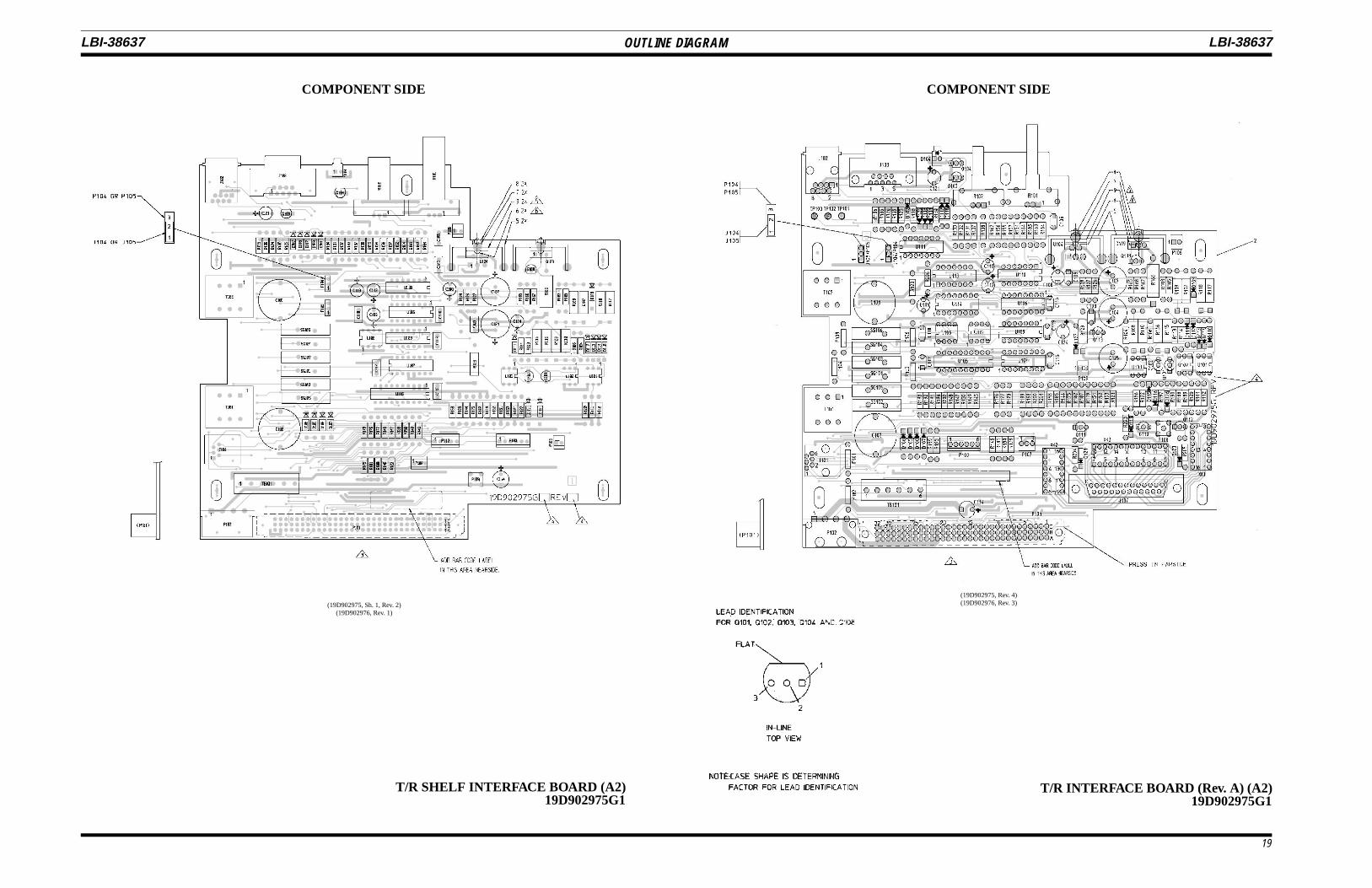
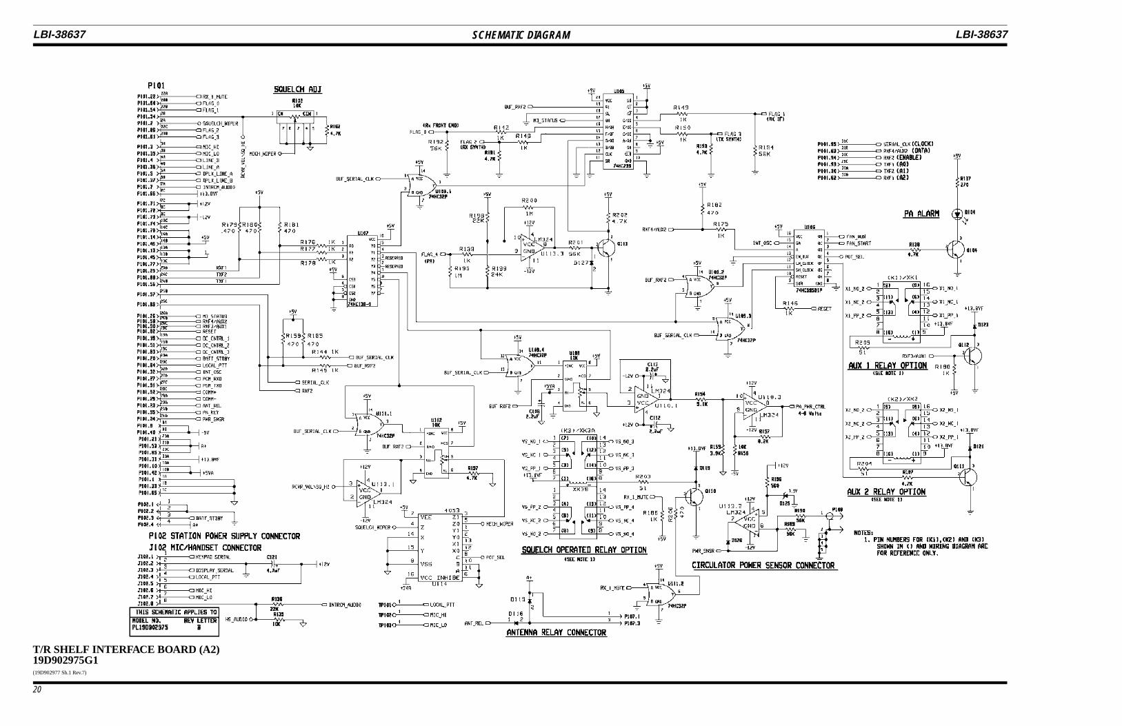
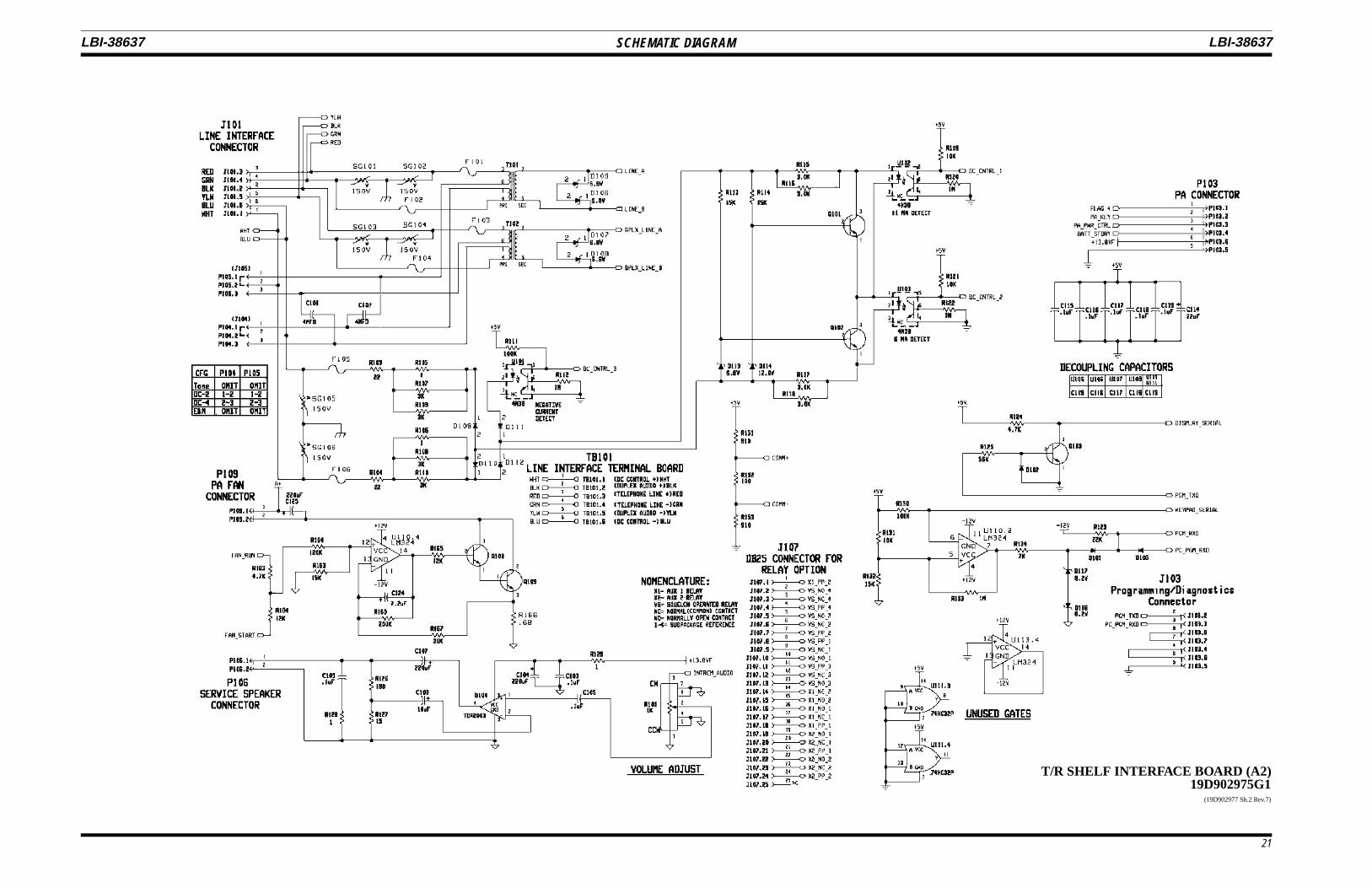
INTERFACE BOARD
Line Interconnect
Audio and control currents from a remote unit are connectedto the T/R shelf via TB101 or J101 located on the Interface Board.TB101 is a terminal board and J101 is a 6 pin modular phone jack.TB101 and J101 carry identical pin assignments and are con-nected in parallel on the pwb.
Line audio from the base station to a remote unit is coupledonto the line via transformer T101 over signals LINE_A andLINE_B. T101 is designed for a termination impedance of 600ohms, which should be provided by the remote unit. In two wireapplications, line audio from the remote unit is coupled to theSystem Module by T101, also, over signals LINE_A andLINE_B. For 4 wire systems, line audio from the remote iscoupled to the System Module by transformer T102 over signalsDPLX_LINE_A and DPLX_LINE_B. The T/R shelf provides theappropriate 600 ohm line termination for T101 and T102.
DC Control
The current detection electronics indicate the following con-ditions:
1. No current
2. Negative current (in excess of 2 mA)
3. Current magnitude in excess of 5 mA
4. Current magnitude in excess of 10 mA.
Control current passes through a full wave bridge rectifierconsisting of diodes D109, D110, D111, and D112. Negativecurrent is directed through U101, D111, through the 6 mA and 12mA detectors and then out through D110. This negative currentcauses the photo-transistor of U101 to saturate and thus pull theoutput DC_CNTRL_3 low.
Positive current flows through D112 of the bridge into thecurrent level sense portion of the circuit which consists of Q101,U102, Q102, U103, D113, and D114. At current levels below 6mA, Q101 and Q102 are "on" and act as current hogs preventingoptoisolators U102 and U103 from turning "on". As the currentlevel approaches 6 mA, the voltage developed across the parallelcombination of R117 and R118 exceeds the sum of the zenervoltage across D113 and the base-emitter voltage of Q102 whichforces Q102 into cutoff. With no current flow through Q102, the6 mA is forced through U103 which turns it on. As the currentlevel continues to increase toward 11 mA, the same switchingaction occurs with Q101 and U102 but at a point set by D114.With 11 mA of current DC_CNTRL_1 is true (active low) as wellas DC_CNTRL_2 (because 11 mA is greater than 6 mA).
Table 4 - Decoding Truth Table
CONTROLCURRENT
(mA)
DC CTRL 1 DC CTRL 2 DC CTRL 3
0 High High High
-11 Low Low Low
+11 Low Low High
-2.5 High High Low
-6 High Low Low
+6 High Low High
E & M Signalling
For E & M signalling applications, the E & M voltage isapplied at TB101 pins 1 and 6 (or J101) which connect to the DCcurrent detection circuit. For 24V signalling, about 8 mA ofcurrent is detected as 6 mA by U103 and output onDC_CNTRL_2. For 48V signalling, R105 and R106 should beremoved in order to maintain 8 mA of E & M current. RemoveP104 and P105 jumpers located on the Interface Board.
Audio Amplifier
Audio power amplifier U104 provides 1 watt of audio to thelocal service speaker. For convenience,the volume adjust potR101 is accessible from the front of the station. Resistors R126and R127 form the gain setting feedback network and C109 andR128 provide compensation for loop stability.
LBI-38637 LBI-38637
9
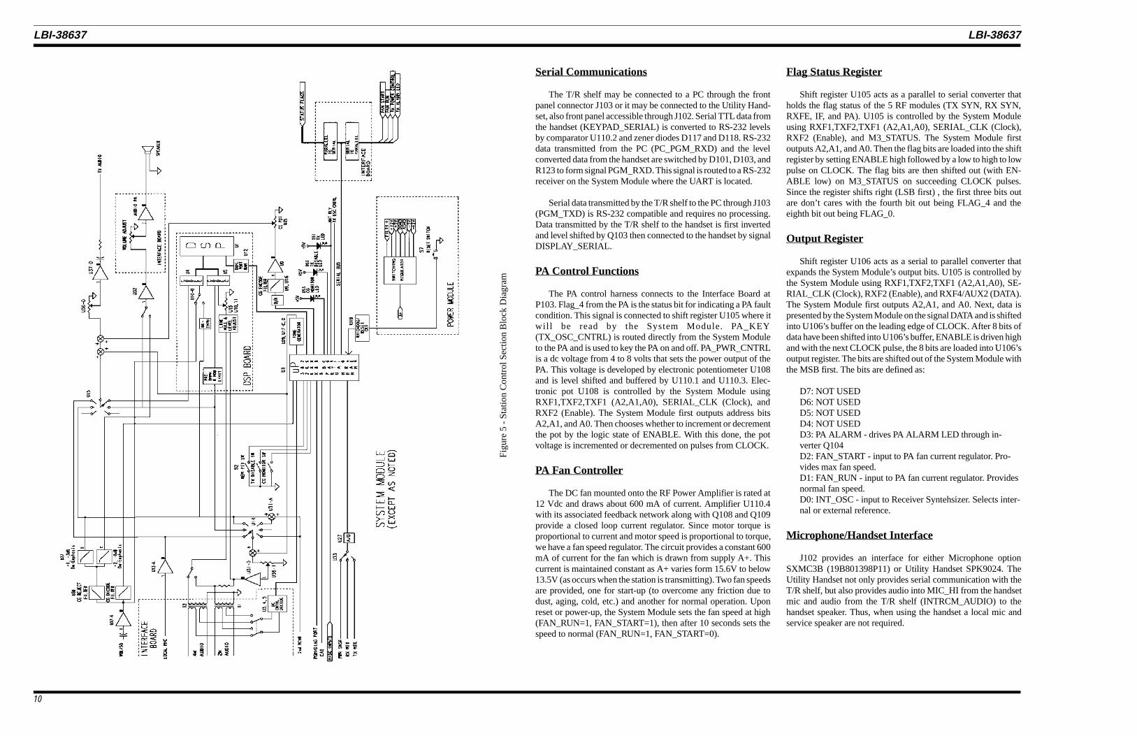
Serial Communications
The T/R shelf may be connected to a PC through the frontpanel connector J103 or it may be connected to the Utility Hand-set, also front panel accessible through J102. Serial TTL data fromthe handset (KEYPAD_SERIAL) is converted to RS-232 levelsby comparator U110.2 and zener diodes D117 and D118. RS-232data transmitted from the PC (PC_PGM_RXD) and the levelconverted data from the handset are switched by D101, D103, andR123 to form signal PGM_RXD. This signal is routed to a RS-232receiver on the System Module where the UART is located.
Serial data transmitted by the T/R shelf to the PC through J103(PGM_TXD) is RS-232 compatible and requires no processing.Data transmitted by the T/R shelf to the handset is first invertedand level shifted by Q103 then connected to the handset by signalDISPLAY_SERIAL.
PA Control Functions
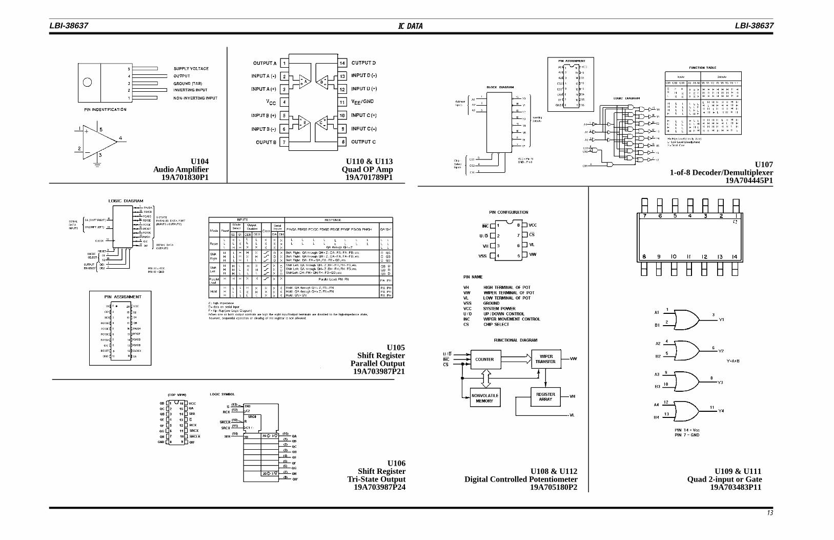
The PA control harness connects to the Interface Board atP103. Flag_4 from the PA is the status bit for indicating a PA faultcondition. This signal is connected to shift register U105 where itwil l be read by the System Module. PA_KEY(TX_OSC_CNTRL) is routed directly from the System Moduleto the PA and is used to key the PA on and off. PA_PWR_CNTRLis a dc voltage from 4 to 8 volts that sets the power output of thePA. This voltage is developed by electronic potentiometer U108and is level shifted and buffered by U110.1 and U110.3. Elec-tronic pot U108 is controlled by the System Module usingRXF1,TXF2,TXF1 (A2,A1,A0), SERIAL_CLK (Clock), andRXF2 (Enable). The System Module first outputs address bitsA2,A1, and A0. Then chooses whether to increment or decrementthe pot by the logic state of ENABLE. With this done, the potvoltage is incremented or decremented on pulses from CLOCK.
PA Fan Controller
The DC fan mounted onto the RF Power Amplifier is rated at12 Vdc and draws about 600 mA of current. Amplifier U110.4with its associated feedback network along with Q108 and Q109provide a closed loop current regulator. Since motor torque isproportional to current and motor speed is proportional to torque,we have a fan speed regulator. The circuit provides a constant 600mA of current for the fan which is drawn from supply A+. Thiscurrent is maintained constant as A+ varies form 15.6V to below13.5V (as occurs when the station is transmitting). Two fan speedsare provided, one for start-up (to overcome any friction due todust, aging, cold, etc.) and another for normal operation. Uponreset or power-up, the System Module sets the fan speed at high(FAN_RUN=1, FAN_START=1), then after 10 seconds sets thespeed to normal (FAN_RUN=1, FAN_START=0).
Flag Status Register
Shift register U105 acts as a parallel to serial converter thatholds the flag status of the 5 RF modules (TX SYN, RX SYN,RXFE, IF, and PA). U105 is controlled by the System Moduleusing RXF1,TXF2,TXF1 (A2,A1,A0), SERIAL_CLK (Clock),RXF2 (Enable), and M3_STATUS. The System Module firstoutputs A2,A1, and A0. Then the flag bits are loaded into the shiftregister by setting ENABLE high followed by a low to high to lowpulse on CLOCK. The flag bits are then shifted out (with EN-ABLE low) on M3_STATUS on succeeding CLOCK pulses.Since the register shifts right (LSB first) , the first three bits outare don’t cares with the fourth bit out being FLAG_4 and theeighth bit out being FLAG_0.
Output Register
Shift register U106 acts as a serial to parallel converter thatexpands the System Module’s output bits. U105 is controlled bythe System Module using RXF1,TXF2,TXF1 (A2,A1,A0), SE-RIAL_CLK (Clock), RXF2 (Enable), and RXF4/AUX2 (DATA).The System Module first outputs A2,A1, and A0. Next, data ispresented by the System Module on the signal DATA and is shiftedinto U106’s buffer on the leading edge of CLOCK. After 8 bits ofdata have been shifted into U106’s buffer, ENABLE is driven highand with the next CLOCK pulse, the 8 bits are loaded into U106’soutput register. The bits are shifted out of the System Module withthe MSB first. The bits are defined as:
D7: NOT USEDD6: NOT USEDD5: NOT USEDD4: NOT USEDD3: PA ALARM - drives PA ALARM LED through in-verter Q104D2: FAN_START - input to PA fan current regulator. Pro-vides max fan speed.D1: FAN_RUN - input to PA fan current regulator. Providesnormal fan speed.D0: INT_OSC - input to Receiver Syntehsizer. Selects inter-nal or external reference.
Microphone/Handset Interface
J102 provides an interface for either Microphone optionSXMC3B (19B801398P11) or Utility Handset SPK9024. TheUtility Handset not only provides serial communication with theT/R shelf, but also provides audio into MIC_HI from the handsetmic and audio from the T/R shelf (INTRCM_AUDIO) to thehandset speaker. Thus, when using the handset a local mic andservice speaker are not required.
Fig
ure
5 -
Sta
tion
Co
ntro
l Sec
tion
Blo
ck D
iag
ram
LBI-38637 LBI-38637
10
Circulator Connector
SMA type connector P108 connects the optional circulatorpower sense signal to the Interface Board and through the back-plane to the System Module via signal PWR_SNSR. This signalis sampled by the System Module while the station is transmittingand if the voltage exceeds a predefined limit (indication of faultin antenna system) the System Module will unkey the transmitterand the PA ALARM LED will flash. The transmitter will bedisabled until a system reset occurs.
Squelch Adjustment
The station provides for local squelch adjustment throughfront panel accessible R102 or remote adjustment via handset orremote/diagnostic ports. Signal RCVR_VOL_SQ_HI is con-nected to two separate voltage divider’s formed by R102-R162and U112-R197. U112 is a digitally programmable potentiometerthat is adjusted in a manner similar to U108, the PA poweradjustment potentiometer. The output of each divider is connectedto analog switch U114. Thus the signal SQUELCH_WIPER,which is fed back to the IF Module, can be selected from eithersource. It is important to note that if digital (remote) adjustmentis selected, the manual adjustment via R102 is disabled.
Relay Options (SXSU3D)
Stations equipped with REV A or higher interface boards, aredesigned to accept optional relays. The relays include a SOR(Squelch Operated Relay) and two AUX relays, AUX1 and AUX2.
The SOR (K3) contains four form "C" contacts and is ratedfor 2 amps at 20 Vdc. The relay operates under control of signalRX_1_MUTE, which is derived from CAS, with the coil of K3being picked up by transistor switch Q110.
AUX1 relay (K1) and AUX2 relay (K2) each contain two form"C" contacts and operate under remote control. When AUX1function is started via remote control, the system microprocessorsets signal RXF3/AUX1 to logic high which turns on transistorswitch Q112 picking up the coil of K1. When AUX2 function isstarted, the system microprocessor sets bit 4 of output registerU106 high, turning on transistor switch Q112 picking up the coilof K2. When the AUX functions are stopped, the control bits aretoggled, and the relay coil drops out.
T/R SHELF ALIGNMENT
Instructions for system alignment, including the T/R Shelf, arecontained in LBI-38636.
MAINTENANCE
PARTS LIST
CMOS Integrated Circuit devicesused in this equipment can be de-stroyed by static discharges. Beforehandling one of these devices, the
service person should discharge himself by touchingthe case of a bench test instrument that has a 3-prongpower cord connected to an outlet with a knowngood earth ground. When soldering or de-solderinga CMOS device, the soldering iron should also havea 3-prong power cord connected to a outlet with aknown good earth ground. A battery operated sol-dering iron may be used in place of the regularsoldering iron.
CAUTION
MASTR III STATION T/R SHELF19D902839G1
SYMBOL PART NO. DESCRIPTION
- - - - - - - - - - ASSEMBLIES - - - - - - - - -
A1 BACKPLANE BOARD19D902947G1
- - - - - - - - - - - JACKS - - - - - - - - - - -
J1thruJ9
19B801587P8 Connector, DIN: 96-position; sim to AMP 650963-4.
J10 19B801587P11 Connector, DIN: 96-position, right angle mounting;sim to AMP 650895-4.
Changes in the equipment to improve performance or to simplify circuitsare identified by a "Revision Letter" which is stamped after the modelnumber of the unit. The revision stamped on the unit includes all previousrevisions. Refer to the Parts List for the descriptions of parts affected bythese revisions.
REV. A - INTERFACE BOARD 19D902975G1To add new features to board including SOR and DSP. New boardis backward compatible.Added C125, D119-D127, R132-R134 and R186-R205, Q110-Q113 and I111-U114.Changed C103, C105, C109, C115-C119, D105-D108, R111,R158, R179-R182 and R185.C103, C105, C109 and C115-C119 were: Tantalum: 0.1 µF±20%, 35 VDCW.D105-D108 were: 19J706030P2.R111 was: H212CRP310C - 10K ohms ±5%, 1/4 w.R158 was: H212CRP247C - 4.7K ohms ±5%, 1/4 w.R179-R182 were: H212CRP247C - 4.7K ohms ±5%, 1/4 w.R185 was: H212CRP247C - 10K ohms ±5%, 1/4 w.
REV. B - INTERFACE BOARD 19D902975G1To make RX_1_MUTE Logic Level compatible with GETC levelrequirement. Added R206 and buffer U111 betweenRX_1_MUTE and the base of Q110.