39
LCD MPPT 20 / 40 / 60 / 100A User Manual Manual Version: LCDMPPT-2016-4 BATTERY = 12.5V EQUALISE AT ! = 10.0A PANEL = 24.0V OUTPUT POWER = 125.0W
| Date post: | 11-Nov-2018 |
| Category: |
Documents |
| Upload: | truongdiep |
| View: | 219 times |
| Download: | 0 times |
LCD MPPT 20 / 40 / 60 / 100A
User Manual
Manual Version: LCDMPPT-2016-4
BATTERY = 12.5V EQUALISE AT ! = 10.0A PANEL = 24.0V OUTPUT POWER = 125.0W

TABLE OF CONTENTS
IMPORTANT INFORMATION AND SAFETY INSTRUCTIONS ................................................... 1
1. INTRODUCTION ............................................................................................................ 3
1.1 General Description ........................................................................................................ 3
1.2 Key Features .................................................................................................................. 3
1.3 Clarification around the purpose and connection of the MPPT. ...................................... 4
1.4 MPPT Operation Description .......................................................................................... 6
2. MPPT OVERVIEW ......................................................................................................... 7
3. MPPT INSTALLATION ................................................................................................... 8
3.1 MPPT minimum installation clearance distance .............................................................. 8
3.2 MPPT Installation Instructions: ....................................................................................... 8
3.3 LCD MPPT Installation Diagram ..................................................................................... 9
3.4 Recommended Array Sizes .......................................................................................... 10
3.5 Maximum Panel Voltage (Voc) Per Battery Bank.......................................................... 10
4. WIRING INFORMATION .............................................................................................. 12
4.1 Cable Sizes ................................................................................................................... 12
4.2 Battery Connection Methods ......................................................................................... 13
4.2.1 Series Connection .................................................................................................. 13
4.2.2 Parallel Connection ................................................................................................ 13
4.2.3 Series and Parallel Connection .............................................................................. 13
4.3 Basic MPPT Wiring Diagram Examples ........................................................................ 14
4.3.1 2 x Panels Connected in Series ............................................................................. 14
4.3.2 2 x Panels Connected In Parallel ........................................................................... 15
4.3.3 2 Series Strings Connected in Parallel .................................................................. 15
4.3.4 Connecting 2 x MPPT’s in Parallel ......................................................................... 16
4.4 Basic System Diagram .................................................................................................. 17
5. MPPT OPERATION ..................................................................................................... 18
5.1 Front Panel Description ................................................................................................ 18
5.2 Checks Prior To Start-Up .............................................................................................. 19
5.3 MPPT Start-up Procedure ............................................................................................. 19

6. LCD MPPT OPERATION ............................................................................................. 20
6.1 Float Mode .................................................................................................................... 21
6.2 Panels Limiting Energy ................................................................................................. 21
6.3 Equalise Mode .............................................................................................................. 21
6.4 Boost Charge Mode ...................................................................................................... 21
6.5 Float Mode .................................................................................................................... 21
6.6 Checking the MPPT Firmware ...................................................................................... 22
6.7 Turning the MPPT OFF. ................................................................................................ 22
6.8 Data Logging Operation ................................................................................................ 22
7. SETUP MENU SETTINGS ........................................................................................... 23
8. Programming the MPPT ............................................................................................... 24
8.1 Float Voltage ................................................................................................................. 24
8.2 Boost Voltage ............................................................................................................... 25
8.3 Boost to Float Voltage ................................................................................................... 25
8.4 Boost to Float Current ................................................................................................... 25
8.5 Equalise Charge Mode ................................................................................................. 25
8.6 Battery Set Voltage ....................................................................................................... 26
8.7 Charge Limit ................................................................................................................. 26
8.8 External Output Connections: ....................................................................................... 26
8.9 Set Operation Mode ...................................................................................................... 26
8.10 Solar or Wind Settings .................................................................................................. 26
8.11 Change time settings .................................................................................................... 27
8.12 Communication Setting ................................................................................................. 27
9. EXTERNAL CONNECTIONS ....................................................................................... 27
9.1 Solar Assist signal ......................................................................................................... 28
9.2 Day Night Signal ........................................................................................................... 28
9.3 Load Shed Disconnect .................................................................................................. 28
9.3.1 Load Shed Disconnect Voltage .............................................................................. 28
9.3.2 Load Reconnect Voltage ........................................................................................ 28
9.4 Battery Temp and Battery Voltage Sensor .................................................................... 29

9.5 To reset the MPPT to factory defaults ........................................................................... 29
The following screen will appear ................................................................................................ 29
10. TROUBLESHOOTING.................................................................................................. 30
10.1 Panel Output Power Low .............................................................................................. 30
10.2 High Panel Voltage ....................................................................................................... 30
10.3 Open Circuit Voltage Higher Than 150 VDC ................................................................. 30
10.4 Battery Voltage Higher Than 60Vdc .............................................................................. 30
10.5 Output Short Circuit ...................................................................................................... 31
11. Maintenance and service .............................................................................................. 31
12. LCD MPPT SPECIFICATIONS ..................................................................................... 32
13. LCD MPPT ACCESSORIES ......................................................................................... 33
13.1 Data acquisition software .............................................................................................. 33
13.2 Battery Monitor.............................................................................................................. 33
13.3 Battery Monitor Accessories ......................................................................................... 33
13.3.1 100 A Battery Sensor ............................................................................................. 33
13.3.2 200 A Battery Sensor ............................................................................................. 33
13.3.3 400 A Battery Sensor ............................................................................................. 33
13.3.4 Web-Logger ............................................................................................................ 33
13.3.5 232-485 Converter ................................................................................................. 33
13.4 Programmable Relay .................................................................................................... 33
13.5 PV String Combiner and Surge Protection Box ............................................................ 33
14. DESTRIER ELECTRONICS LIMITED CARRY- IN WARRANTY ................................. 34
15. REGISTRATION OF MY MICROCARE PRODUCT ..................................................... 35
IMPORTANT INFORMATION AND SAFETY INSTRUCTIONS
Installers should be qualified electricians or technicians.
The installation information in the manual is for information purposes only.
The monitoring and operation information in this manual is intended for anyone who needs to operate the MPPT.
The MPPT input cannot be paralleled with another PV array.
Read the instructions carefully before installing and operating the MPPT.
MPPT connection and installation instructions must be followed.
The unit should only be opened by skilled personal.
Keep the MPPT clean and dry.
The MPPT will not operate without batteries connected to the MPPT.
The MPPT should be installed indoors, in a ventilated and dry area.
Mount the MPPT vertically.
Do not install the MPPT on a rugged or inclined surface.
Do not install the MPPT near water or in damp environments.
Do not install the MPPT where it would be exposed to direct sunlight.
Do not remove the MPPT casing.
Keep the MPPT away from heat emitting sources.
Do not block the MPPT ventilation openings.
Do not leave objects on top of the MPPT
Do not expose the MPPT to corrosive gasses.
Install the MPPT away from any explosive gasses.
Ambient temperature: 0°C – 40°C.
Use panels of the same type and size in an array.
Sketches are intended for illustrative purposes only and are not intended to provide an electrical design.
Damage caused by reverse polarity is not covered by warranty.
Do not exceed the MPPT 150 Volt maximum input voltage (Voc) rating.
Refer to your solar module documentation for the worst-case (coldest) module temperature voltage, it should provide the Voc vs. temperature data.
Contact the battery manufacturer or supplier for the correct charging specifications.
Incorrect charging can damage or destroy batteries.
PLEASE BE AWARE:
WARRANTY WILL BE NULL AND VOID IF PANEL
SURGE PROTECTION IS NOT INSTALLED WITH
ALL LCD MPPT INSTALLATIONS
WARNING
High DC voltage present and is capable of causing severe injury. .

2
IMPORTANT INFORMATION AND SAFETY INSTRUCTIONS
Glossary of Terms & Abbreviations . AC Alternating Current
Ah Rated battery capacity specified in Ampere-Hour
.
DC Direct Current
Flooded Battery A lead acid battery with access caps for maintaining the electrolyte - replacing
water lost during recharge operations. Hydrogen gas discharged during normal
recharge
Impp Maximum power point current
Isc Short circuit current
LED Light emitting diode.
Load Electrical appliance or device to which an electrical voltage is fed
MPPT Maximum Power Point Tracking
Off-Grid A system not connected to the grid
PV Photo Voltaic solar power
Sealed Battery A lead acid battery with no access to the electrolyte - either valve regulated or
gel. No hydrogen gas discharge during normal operation
Solar Array A collection of Solar Panels.
SoC State of Charge is the amount of charge in the battery bank expressed as a % of
the battery capacity. When SoC = 100% the battery is fully charged. When the
SoC is 50% then the battery is half charged
State of Charge (SoC) Referring to the battery charge condition.
Voc Open circuit voltage
Vmpp Maximum power point voltage
.
3
INTRODUCTION
1. INTRODUCTION
1.1 General Description
The Microcare Maximum Power Point Tracker Charge Controller is designed to provide maximum
power from the panels into the batteries. Using this system up to 30% more power can be extracted
from the panels than using shunt or series pass PWM controllers. The Microcare MPPT is able to
charge batteries of a lower voltage than the panel system.
A Liquid Crystal Display shows the status of the system and the data logging information. The unit
has various programmable charge regimes which automatically adjust the charge levels when first
starting up or if the battery falls below the minimum voltage.
The MPPT will read the battery voltage when first starting up and select whether it is a 12, 24, 36, or
48 volt battery system. It will then read the panel voltage and find the optimum power point. The
charging, battery values and charge modes are then adjusted. This series features a durable and
continuous 24 hour operation.
The compact and modular design makes installations easy and cost effective. It is a high quality
product that offers the best price/performance ratio in the industry.
1.2 Key Features
4 X 20 LCD Display.
Optional Input and Output circuit breaker protection.
RS232 and Ethernet connectivity.
Fully programmable.
63 Days logger.
High efficiency design with greater than 96% conversion.
Low heat dissipation.
Variable Fan cooling.
Suitable for any battery set between 12 and 48 Volt with 12V increments.
Electronically limited charge current 20, 40, 60, 100 Amps. (Dependent on the
MPPT type)
Maximum open circuit PV Array voltage 135VOC @ 25 ° C (Open Circuit Voltage).
Manual or Auto Equalise selection.
Wall mounted.
4
INTRODUCTION
1.3 Clarification around the purpose and connection of the MPPT.
What is the main purpose of the MPPT?
The MPPT allows you to take advantage of the mathematics behind power conversion and allows
maximum power delivery from the panel.
Let’s look at a typical solar panel (the values will be adjusted to make reading/maths easier).
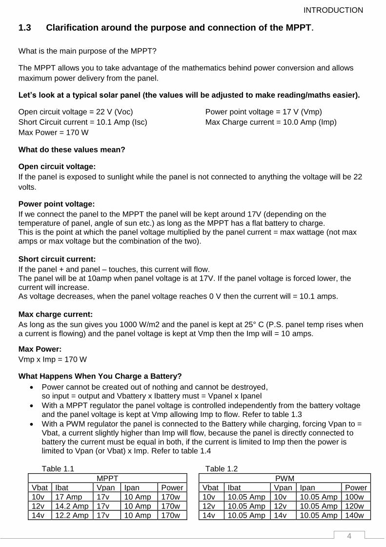
Open circuit voltage = 22 V (Voc) Power point voltage = 17 V (Vmp)
Short Circuit current = 10.1 Amp (Isc) Max Charge current = 10.0 Amp (Imp)
Max Power = 170 W
What do these values mean?
Open circuit voltage:
If the panel is exposed to sunlight while the panel is not connected to anything the voltage will be 22
volts.
Power point voltage:
If we connect the panel to the MPPT the panel will be kept around 17V (depending on the temperature of panel, angle of sun etc.) as long as the MPPT has a flat battery to charge. This is the point at which the panel voltage multiplied by the panel current = max wattage (not max amps or max voltage but the combination of the two). Short circuit current:
If the panel + and panel – touches, this current will flow. The panel will be at 10amp when panel voltage is at 17V. If the panel voltage is forced lower, the current will increase. As voltage decreases, when the panel voltage reaches 0 V then the current will = 10.1 amps. Max charge current:
As long as the sun gives you 1000 W/m2 and the panel is kept at 25° C (P.S. panel temp rises when a current is flowing) and the panel voltage is kept at Vmp then the Imp will = 10 amps.
Max Power:
Vmp x Imp = 170 W
What Happens When You Charge a Battery?
Power cannot be created out of nothing and cannot be destroyed, so input = output and Vbattery x Ibattery must = Vpanel x Ipanel
With a MPPT regulator the panel voltage is controlled independently from the battery voltage and the panel voltage is kept at Vmp allowing Imp to flow. Refer to table 1.3
With a PWM regulator the panel is connected to the Battery while charging, forcing Vpan to = Vbat, a current slightly higher than Imp will flow, because the panel is directly connected to battery the current must be equal in both, if the current is limited to Imp then the power is limited to Vpan (or Vbat) x Imp. Refer to table 1.4 Table 1.1 Table 1.2
MPPT
PWM
Vbat Ibat Vpan Ipan Power
Vbat Ibat Vpan Ipan Power
10v 17 Amp 17v 10 Amp 170w
10v 10.05 Amp 10v 10.05 Amp 100w
12v 14.2 Amp 17v 10 Amp 170w
12v 10.05 Amp 12v 10.05 Amp 120w
14v 12.2 Amp 17v 10 Amp 170w
14v 10.05 Amp 14v 10.05 Amp 140w

5
INTRODUCTION
PWM regulators can produce as low as 100w from a 170w panel under full sunlight condition and a max of about 140w in ideal conditions (battery V, temp, radiation …).
MPPT regulators will always produce 170w in ideal conditions (temp, radiation …) no matter what the battery voltage is.
So now that you know the 1st and foremost importance of the MPPT we can discuss some added advantages.
It is true that a MPPT helps to improve system efficiency by allowing a higher panel voltage to be used, because power stays the same and power = V x I it means that the panel array current will decrease, resulting in less volt drop in the cable, resulting in less power loss in cable. What is important here is that this is only true if you keep the cable / conductor diameter the same when or as you increase the voltage, if you use thinner cable because the current is less then you’re only saving on system installation cost and not gaining any efficiency.
This gain in efficiency is normally almost insignificant when compared to the 1st most important reason for using a MPPT gain of up to 70% increase in power (normally around 30% because battery voltage does not always stay at 10v). Do not use the MPPT to increase panel voltage, increase panel voltage to make your installation easier and more economical. What is very important to note is that there is a limit to how much you can increase the panel voltage on the MPPT. Why is this so?
The MPPT (all step down MPPT battery chargers) uses a Buck regulator circuit to do the power conversion.
These circuits do not operate at max efficiency when the input output voltage ratio is very high.
Try to not exceed a ratio of 1:4, this is especially true on 12v systems . For example:
If you charge a 12v battery do not connect 120v of panels to the MPPT the ratio = 1:10.
The MPPT display a “High Panel voltage” Warning meaning that the MPPT is now operating out of
speck.
For a 12v system your max Charge voltage is 15v, so use a panel array with a power point voltage (Vmp not Voc) between 15v and 60v (1:4 = 15v x 4 = 60v), then the MPPT will be efficient and you will get maximum power transfer efficiency from your MPPT.
In essence your MPPT has 2 paths where the power flow, 1 path steps down and divides the voltage and the other increases and multiplies the current.
If the ratio is 1:10, then each circuit has to work 10 times harder then what it would have worked if the ratio was 1:1.
Having to divide the voltage by 10 and boosting the current 10 fold (turn 1 amp from panel into 10 amps into the battery), the difference in efficiency between 1:1 and 1:4 is minuscule and not worth stressing about but when the ratio becomes greater than 1:6 then the efficiency is notably lower.
6
INTRODUCTION
1.4 MPPT Operation Description
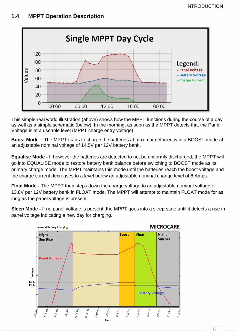
This simple real world illustration (above) shows how the MPPT functions during the course of a day as well as a simple schematic (below). In the morning, as soon as the MPPT detects that the Panel Voltage is at a useable level (MPPT charge entry voltage);
Boost Mode – The MPPT starts to charge the batteries at maximum efficiency in a BOOST mode at an adjustable nominal voltage of 14.5V per 12V battery bank.
Equalise Mode - If however the batteries are detected to not be uniformly discharged, the MPPT will
go into EQUALISE mode to restore battery bank balance before switching to BOOST mode as its
primary charge mode. The MPPT maintains this mode until the batteries reach the boost voltage and
the charge current decreases to a level below an adjustable nominal change level of 6 Amps.
Float Mode - The MPPT then steps down the charge voltage to an adjustable nominal voltage of
13.8V per 12V battery bank in FLOAT mode. The MPPT will attempt to maintain FLOAT mode for as
long as the panel voltage is present.
Sleep Mode - If no panel voltage is present, the MPPT goes into a sleep state until it detects a rise in
panel voltage indicating a new day for charging.
7 7
7
MPPT OVERVIEW
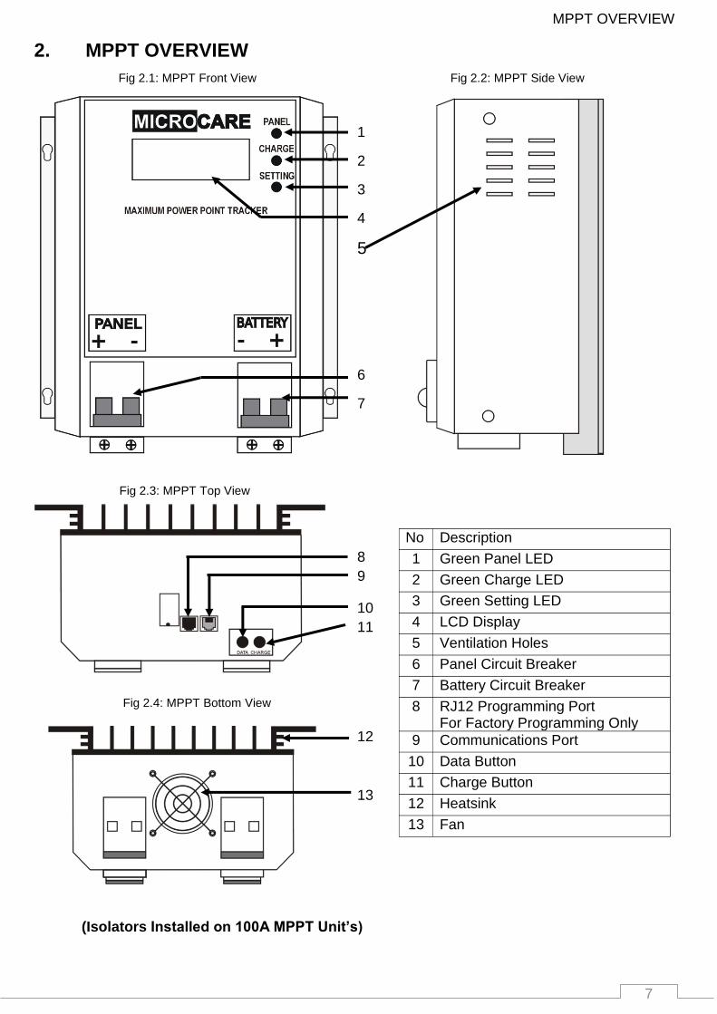
2. MPPT OVERVIEW
(Isolators Installed on 100A MPPT Unit’s)
1
2
3
4
5
6
No Description
1 Green Panel LED
2 Green Charge LED
3 Green Setting LED
4 LCD Display
5 Ventilation Holes
6 Panel Circuit Breaker
7 Battery Circuit Breaker
8 RJ12 Programming Port For Factory Programming Only
9 Communications Port
10 Data Button
11 Charge Button
12 Heatsink
13 Fan
1
2
3
4
5
6
7
8
9
10
11
12
13
1 2
3 4 5
7 7
Fig 2.1: MPPT Front View Fig 2.2: MPPT Side View
Fig 2.3: MPPT Top View
Fig 2.4: MPPT Bottom View

8
MPPT INSTALLATION
3. MPPT INSTALLATION
3.1 MPPT minimum installation clearance distance
Fig 3.1: Minimum clearance distance
Maintain a minimum clearance of 20cm below and around the MPPT to ensure unhindered air
circulation. Mount the solar charge controller as close as possible to the batteries.
3.2 MPPT Installation Instructions:
Read the installation instructions before installing the MPPT.
The MPPT is designed for indoor applications only.
The mounting position should allow for sufficient ventilation and the minimum clearance distance between MPPT’s and other objects, trunking as above.
Mount the MPPT at eye level in order to allow the user to read the LCD Screen
The MPPT must be mounted in a vertical position against a solid wall.
Do not install the MPPT in a sealed container.
Do not install the MPPT near water or in damp environments.
Do not install the MPPT where it would be exposed to direct sunlight or near heat.
Do not install the MPPT on a wooden surface. Only install the MPPT on flat concrete, stone or metal surfaces.
Do not block off the aluminium heat sink and don’t leave objects on top of the MPPT.
Do not expose the MPPT to corrosive battery gases. Corrosion is not covered by warranty.
MPPT operating environment temperature should not exceed: 0˚C - 40˚C.
Ensure that connecting cables are of adequate thickness. Consult the reference table for recommended thicknesses in Cable Connections. Refer to the cable design sheet for correct PV cable thickness.
20cm
Wall
20cm
20cm Cable Trunking
20cm
20cm

9
MPPT INSTALLATION
3.3 LCD MPPT Installation Diagram
Table 3.1: MPPT Mounting Hole Dimensions
MPPT Height Width
20 Amp LCD MPPT 143 mm 204 mm
40 Amp LCD MPPT 143 mm 204 mm
60 Amp LCD MPPT 227 mm 204 mm
100 Amp LCD MPPT 278 mm 204 mm
4 x ANSI B18.6.5M
- M6x1 x 20
Cross Recessed
Pan Head Self
Tapping Screws
204mm
m
143mm
150mm
Airflow
150mm
10
MPPT INSTALLATION
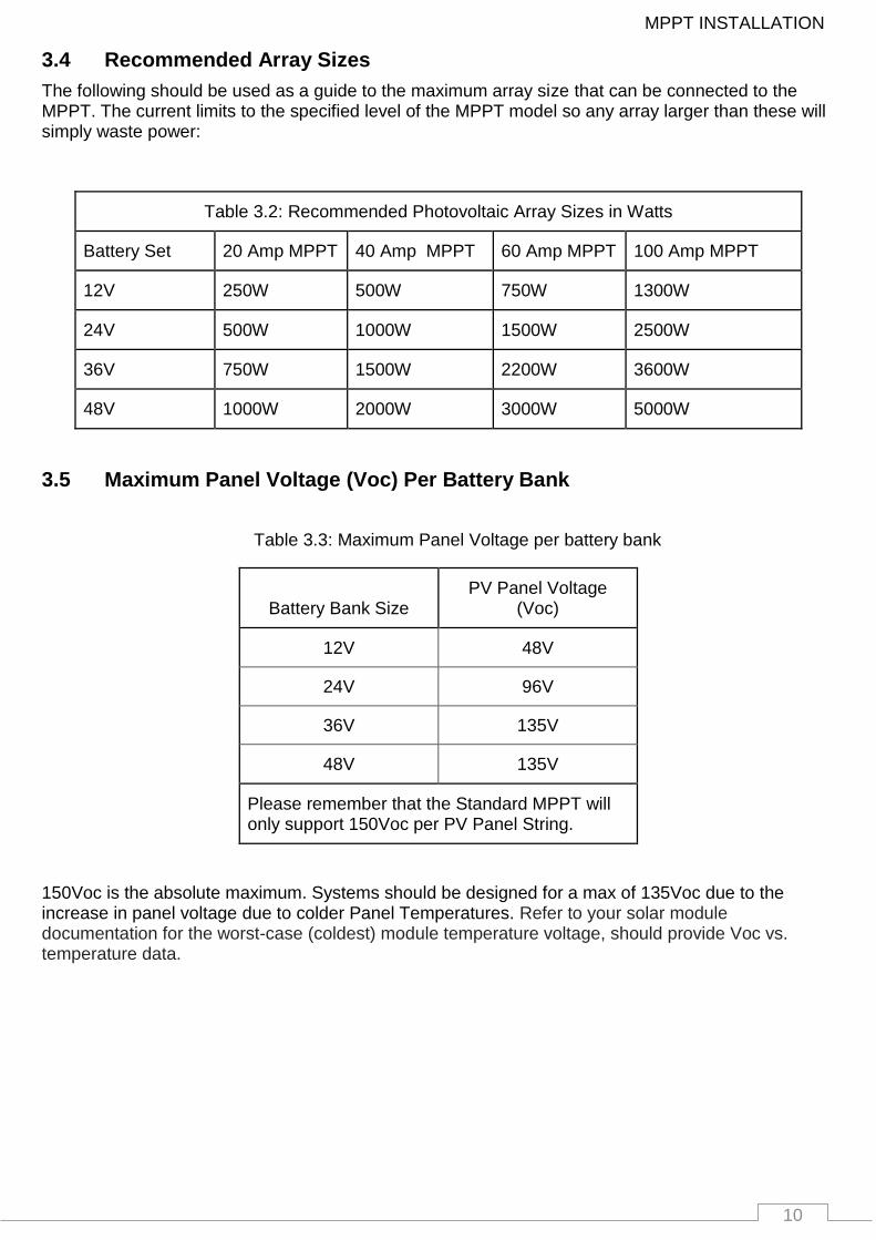
3.4 Recommended Array Sizes
The following should be used as a guide to the maximum array size that can be connected to the MPPT. The current limits to the specified level of the MPPT model so any array larger than these will simply waste power:
Table 3.2: Recommended Photovoltaic Array Sizes in Watts
Battery Set 20 Amp MPPT 40 Amp MPPT 60 Amp MPPT 100 Amp MPPT
12V 250W 500W 750W 1300W
24V 500W 1000W 1500W 2500W
36V 750W 1500W 2200W 3600W
48V 1000W 2000W 3000W 5000W
3.5 Maximum Panel Voltage (Voc) Per Battery Bank
Table 3.3: Maximum Panel Voltage per battery bank
Battery Bank Size PV Panel Voltage
(Voc)
12V 48V
24V 96V
36V 135V
48V 135V
Please remember that the Standard MPPT will only support 150Voc per PV Panel String.
150Voc is the absolute maximum. Systems should be designed for a max of 135Voc due to the increase in panel voltage due to colder Panel Temperatures. Refer to your solar module documentation for the worst-case (coldest) module temperature voltage, should provide Voc vs. temperature data.
11
MPPT INSTALLATION
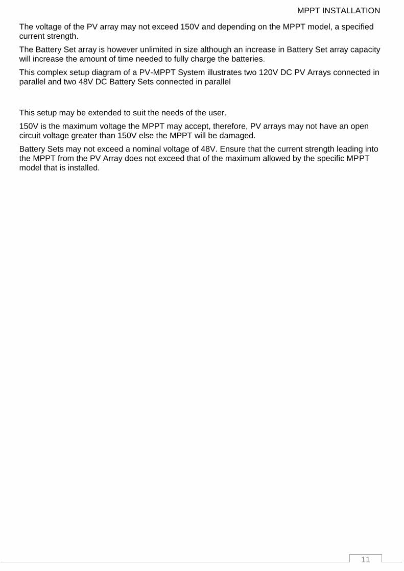
The voltage of the PV array may not exceed 150V and depending on the MPPT model, a specified current strength.
The Battery Set array is however unlimited in size although an increase in Battery Set array capacity will increase the amount of time needed to fully charge the batteries.
This complex setup diagram of a PV-MPPT System illustrates two 120V DC PV Arrays connected in parallel and two 48V DC Battery Sets connected in parallel
This setup may be extended to suit the needs of the user.
150V is the maximum voltage the MPPT may accept, therefore, PV arrays may not have an open circuit voltage greater than 150V else the MPPT will be damaged.
Battery Sets may not exceed a nominal voltage of 48V. Ensure that the current strength leading into the MPPT from the PV Array does not exceed that of the maximum allowed by the specific MPPT model that is installed.
12
WIRING INFORMATION
4. WIRING INFORMATION
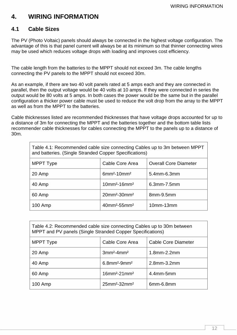
4.1 Cable Sizes The PV (Photo Voltaic) panels should always be connected in the highest voltage configuration. The advantage of this is that panel current will always be at its minimum so that thinner connecting wires may be used which reduces voltage drops with loading and improves cost efficiency. The cable length from the batteries to the MPPT should not exceed 3m. The cable lengths connecting the PV panels to the MPPT should not exceed 30m. As an example, if there are two 40 volt panels rated at 5 amps each and they are connected in parallel, then the output voltage would be 40 volts at 10 amps. If they were connected in series the output would be 80 volts at 5 amps. In both cases the power would be the same but in the parallel configuration a thicker power cable must be used to reduce the volt drop from the array to the MPPT as well as from the MPPT to the batteries. Cable thicknesses listed are recommended thicknesses that have voltage drops accounted for up to a distance of 3m for connecting the MPPT and the batteries together and the bottom table lists recommender cable thicknesses for cables connecting the MPPT to the panels up to a distance of 30m.
Table 4.1: Recommended cable size connecting Cables up to 3m between MPPT and batteries. (Single Stranded Copper Specifications)
MPPT Type Cable Core Area Overall Core Diameter
20 Amp 6mm²-10mm² 5.4mm-6.3mm
40 Amp 10mm²-16mm² 6.3mm-7.5mm
60 Amp 20mm²-30mm² 8mm-9.5mm
100 Amp 40mm²-55mm² 10mm-13mm
Table 4.2: Recommended cable size connecting Cables up to 30m between MPPT and PV panels (Single Stranded Copper Specifications)
MPPT Type Cable Core Area Cable Core Diameter
20 Amp 3mm²-4mm² 1.8mm-2.2mm
40 Amp 6.8mm²-9mm² 2.8mm-3.2mm
60 Amp 16mm²-21mm² 4.4mm-5mm
100 Amp 25mm²-32mm² 6mm-6.8mm
13
WIRING INFORMATION
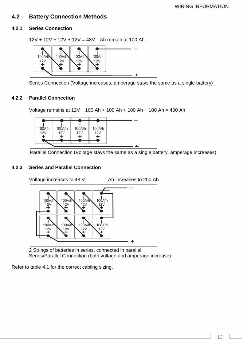
4.2 Battery Connection Methods
4.2.1 Series Connection
12V + 12V + 12V + 12V = 48V Ah remain at 100 Ah
Series Connection (Voltage increases, amperage stays the same as a single battery)
4.2.2 Parallel Connection
Voltage remains at 12V 100 Ah + 100 Ah + 100 Ah + 100 Ah = 400 Ah
Parallel Connection (Voltage stays the same as a single battery, amperage increases)
4.2.3 Series and Parallel Connection
Voltage increases to 48 V Ah increases to 200 Ah
2 Strings of batteries in series, connected in parallel Series/Parallel Connection (both voltage and amperage increase)
Refer to table 4.1 for the correct cabling sizing.
14
WIRING INFORMATION
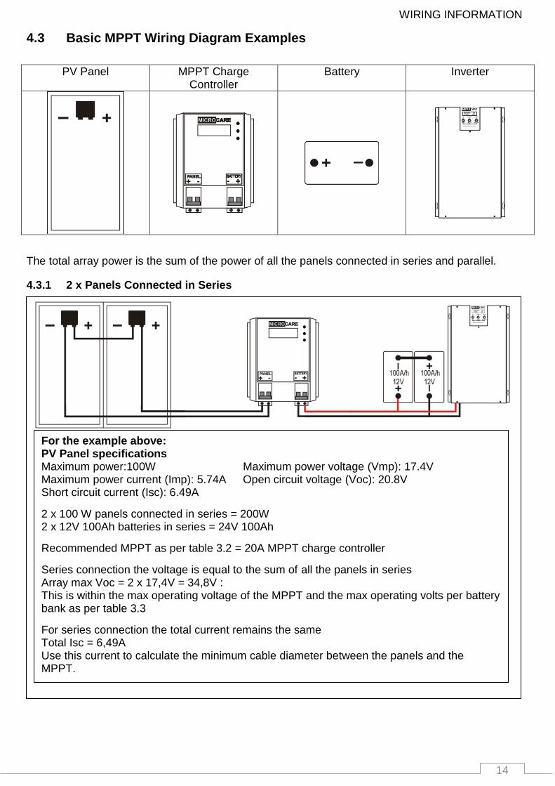
4.3 Basic MPPT Wiring Diagram Examples
PV Panel MPPT Charge Controller
Battery Inverter
The total array power is the sum of the power of all the panels connected in series and parallel.
4.3.1 2 x Panels Connected in Series
For the example above: PV Panel specifications
Maximum power:100W Maximum power voltage (Vmp): 17.4V Maximum power current (Imp): 5.74A Open circuit voltage (Voc): 20.8V Short circuit current (Isc): 6.49A
2 x 100 W panels connected in series = 200W 2 x 12V 100Ah batteries in series = 24V 100Ah
Recommended MPPT as per table 3.2 = 20A MPPT charge controller
Series connection the voltage is equal to the sum of all the panels in series Array max Voc = 2 x 17,4V = 34,8V : This is within the max operating voltage of the MPPT and the max operating volts per battery bank as per table 3.3
For series connection the total current remains the same Total Isc = 6,49A Use this current to calculate the minimum cable diameter between the panels and the MPPT.
15
WIRING INFORMATION
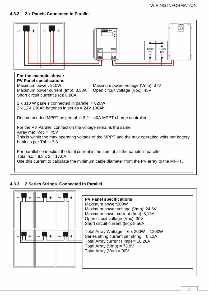
4.3.2 2 x Panels Connected In Parallel
4.3.3 2 Series Strings Connected in Parallel
For the example above: PV Panel specifications
Maximum power: 310W Maximum power voltage (Vmp): 37V Maximum power current (Imp): 8,38A Open circuit voltage (Voc): 45V Short circuit current (Isc): 8,80A
2 x 310 W panels connected in parallel = 620W 2 x 12V 100Ah batteries in series = 24V 100Ah Recommended MPPT as per table 3.2 = 40A MPPT charge controller For the PV Parallel connection the voltage remains the same Array max Voc = 45V : This is within the max operating voltage of the MPPT and the max operating volts per battery bank as per Table 3.3 For parallel connection the total current is the sum of all the panels in parallel Total Isc = 8,8 x 2 = 17,6A Use this current to calculate the minimum cable diameter from the PV array to the MPPT.
PV Panel specifications
Maximum power:200W Maximum power voltage (Vmp): 24,6V Maximum power current (Imp): 8,13A Open circuit voltage (Voc): 30V Short circuit current (Isc): 8,56A
Total Array Wattage = 6 x 200W = 1200W Series string current per string = 8,13A Total Array current ( Imp) = 16,26A Total Array (Vmp) = 73,8V Total Array (Voc) = 90V
16
WIRING INFORMATION
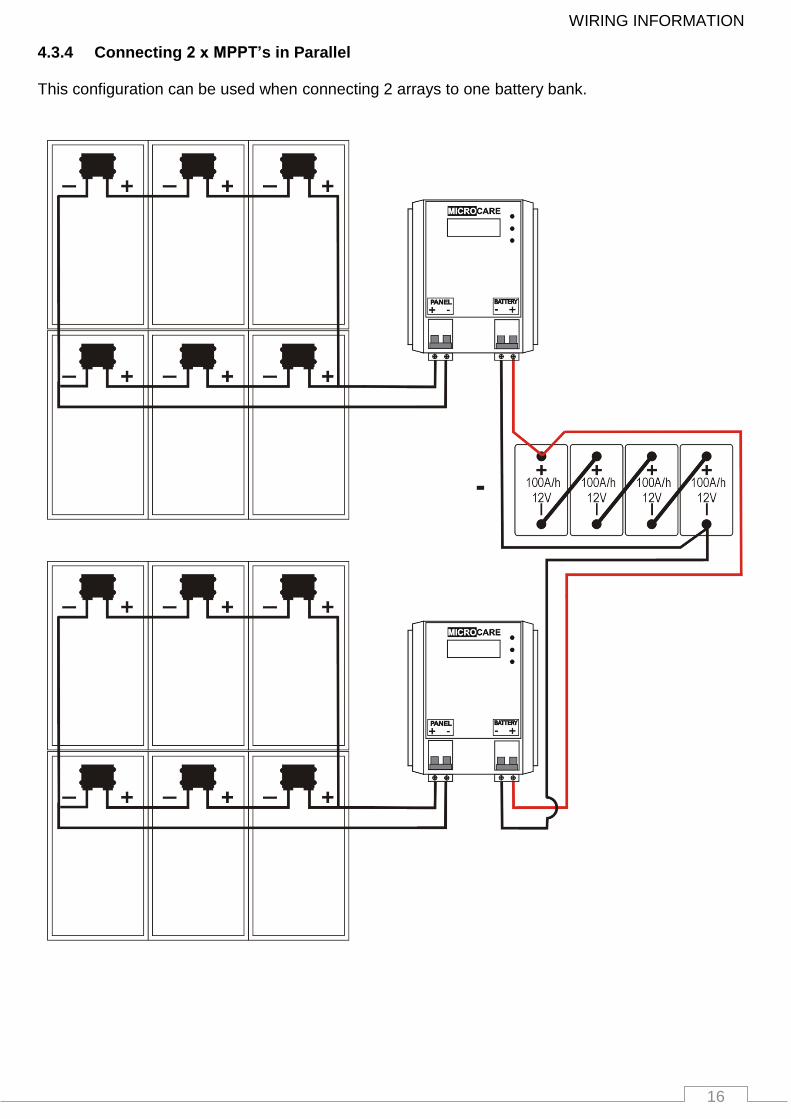
4.3.4 Connecting 2 x MPPT’s in Parallel This configuration can be used when connecting 2 arrays to one battery bank.
17
WIRING INFORMATION
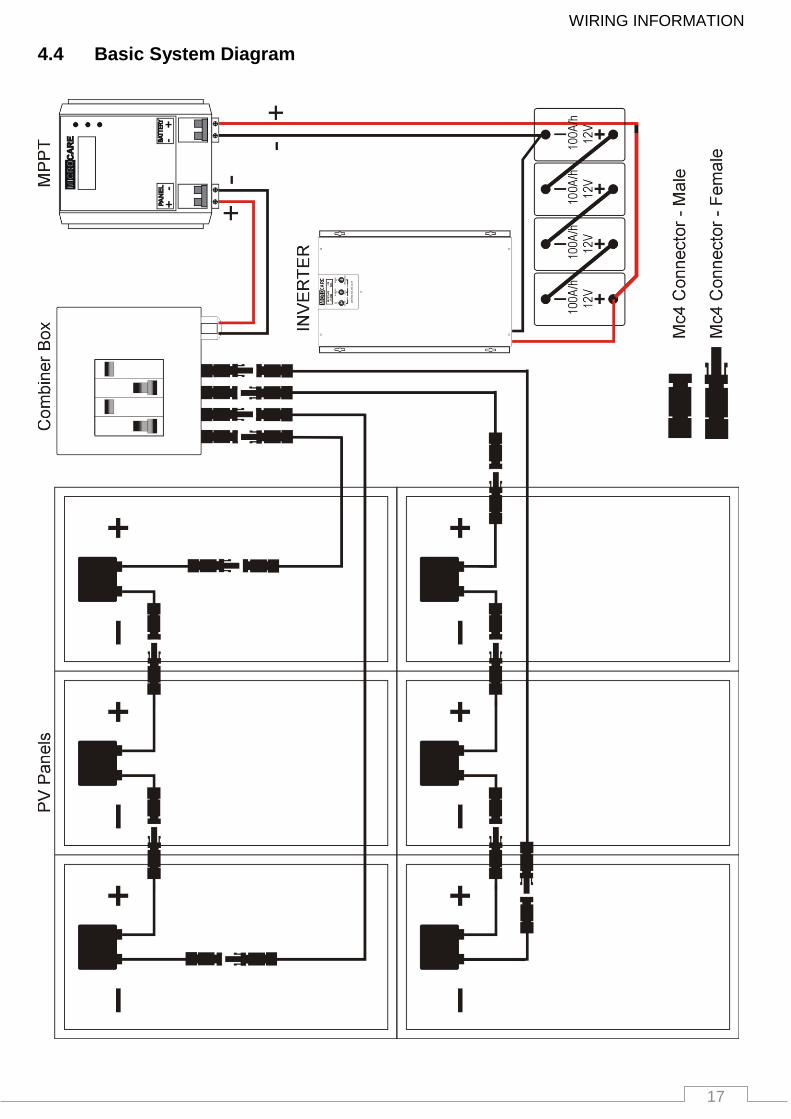
4.4 Basic System Diagram
18
MPPT OPERATION
5. MPPT OPERATION
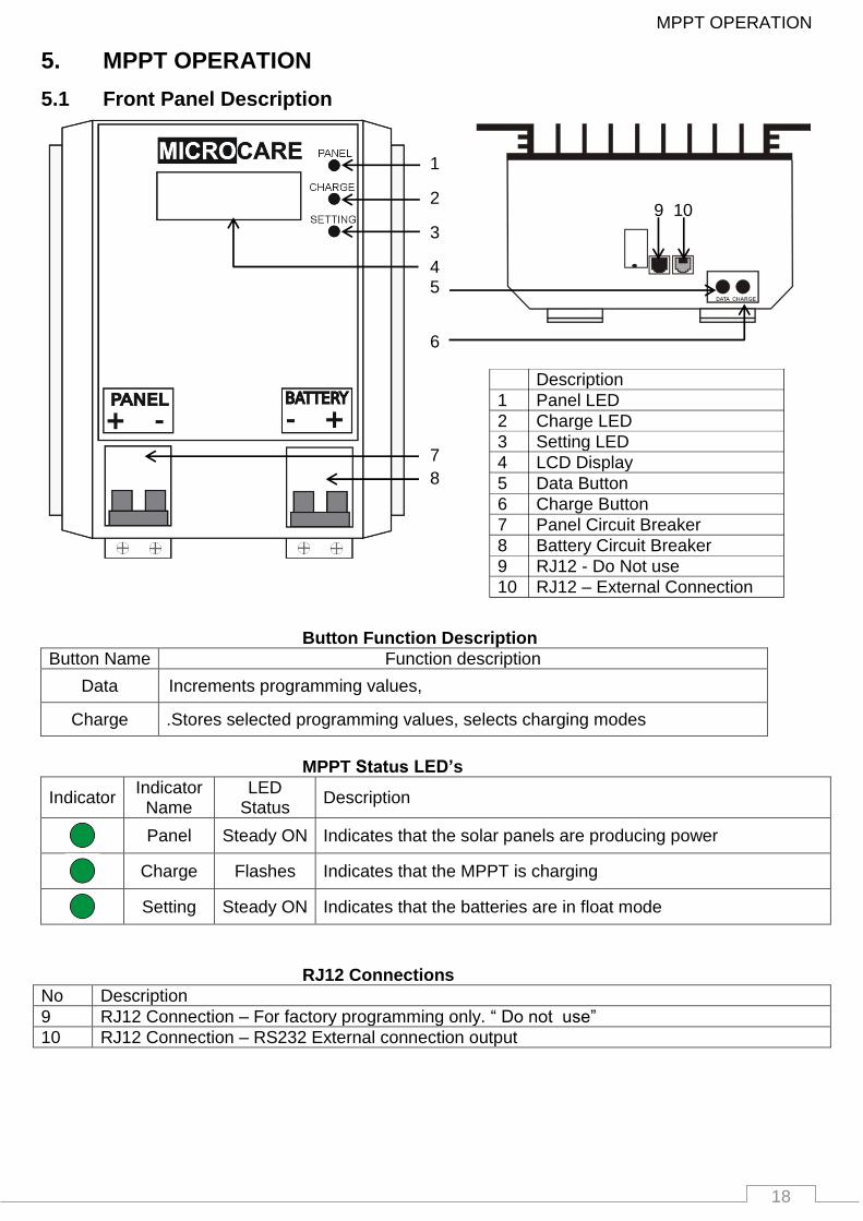
5.1 Front Panel Description
Button Function Description
Button Name Function description
Data Increments programming values,
Charge .Stores selected programming values, selects charging modes
MPPT Status LED’s
Indicator Indicator
Name LED
Status Description
Panel Steady ON Indicates that the solar panels are producing power
Charge Flashes Indicates that the MPPT is charging
Setting Steady ON Indicates that the batteries are in float mode
RJ12 Connections
No Description
9 RJ12 Connection – For factory programming only. “ Do not use”
10 RJ12 Connection – RS232 External connection output
1
2
3
4 5
6
7
8
Description
1 Panel LED
2 Charge LED
3 Setting LED
4 LCD Display
5 Data Button
6 Charge Button
7 Panel Circuit Breaker
8 Battery Circuit Breaker
9 RJ12 - Do Not use
10 RJ12 – External Connection
9 10
19
MPPT OPERATION
5.2 Checks Prior To Start-Up
Ensure the MPPT is mounted vertically.
Check input output cables are secured.
Check the polarity of the panel and battery and they are correct.
Check if the Panel Voltage meets the MPPT rating required.
5.3 MPPT Start-up Procedure
Always turn on battery breaker first.
Wait until MPPT Display states that the MPPT is sleeping.
Turn on Panel Breaker.
MPPT will track the PV Panels.
MPPT will start charging the batteries.
PLEASE BE AWARE:
WARRANTY WILL BE NULL AND VOID IF PANEL
SURGE PROTECTION IS NOT INSTALLED WITH
ALL LCD MPPT INSTALLATIONS
20
LCD MPPT OPERATION
. . . Start up . . .
Checking Batteries
12 volt system
....................
TRACKING
MAXIMUM POWER POINT
V power point...xxxV
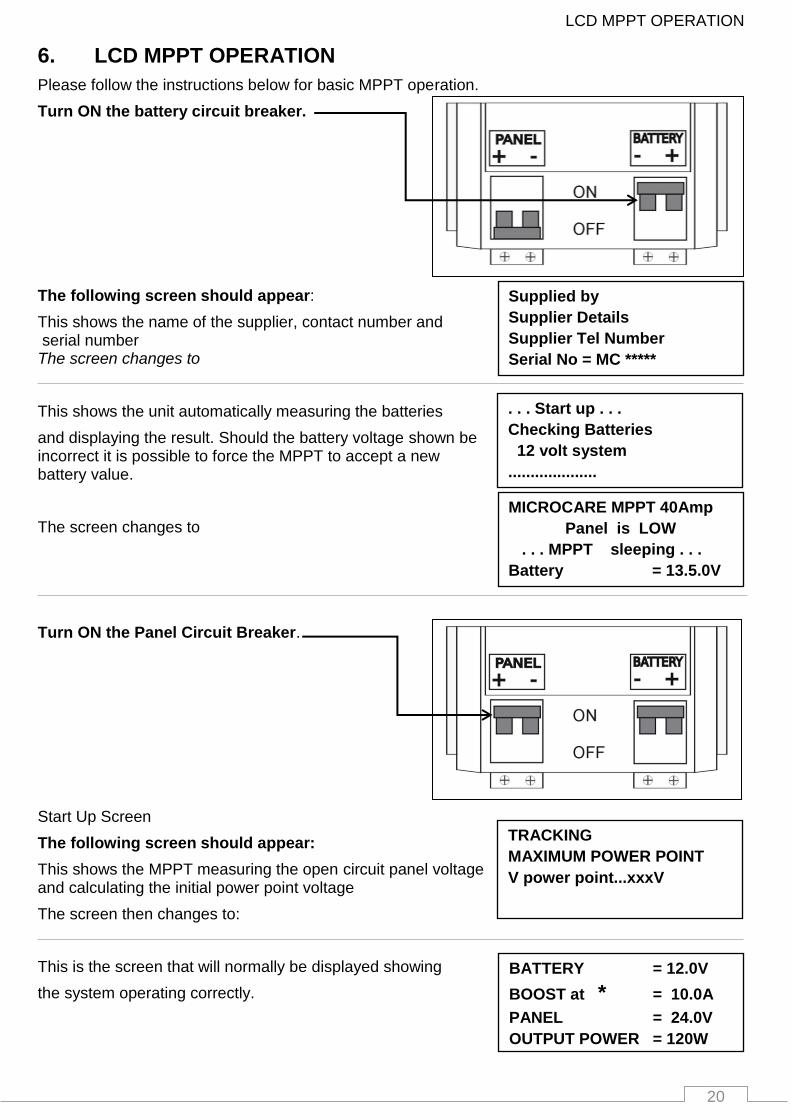
6. LCD MPPT OPERATION
Please follow the instructions below for basic MPPT operation.
Turn ON the battery circuit breaker.
The following screen should appear:
This shows the name of the supplier, contact number and serial number The screen changes to
This shows the unit automatically measuring the batteries
and displaying the result. Should the battery voltage shown be incorrect it is possible to force the MPPT to accept a new battery value.
The screen changes to
Turn ON the Panel Circuit Breaker.
Start Up Screen
The following screen should appear:
This shows the MPPT measuring the open circuit panel voltage and calculating the initial power point voltage
The screen then changes to:
This is the screen that will normally be displayed showing
the system operating correctly.
Supplied by
Supplier Details
Supplier Tel Number
Serial No = MC *****
BATTERY = 12.0V
BOOST at * = 10.0A
PANEL = 24.0V
OUTPUT POWER = 120W
MICROCARE MPPT 40Amp
Panel is LOW
. . . MPPT sleeping . . .
Battery = 13.5.0V
21
LCD MPPT OPERATION
BATTERY * = 13.8 V
FLOAT AT = 1.0 A
PANEL = 24.0 V
OUTPUT POWER.. = 13.8 W
BATTERY = 12.0 V
BOOST at = 10.0 A
PANEL * = 24.0 V
OUTPUT POWER.. = 120.0W
BATTERY = 12.5V
EQUALISE AT ! = 10.0A
PANEL = 24.0V
OUTPUT POWER.. = 125.0W
BATTERY * = 14.5V
BOOST at = 5.0A
PANEL = 24.0V
OUTPUT POWER.. = 72.5W
BATTERY * = 13.8 V
FLOAT at = 1.0 A
PANEL = 28.0 V
OUTPUT POWER...= 13.8 W
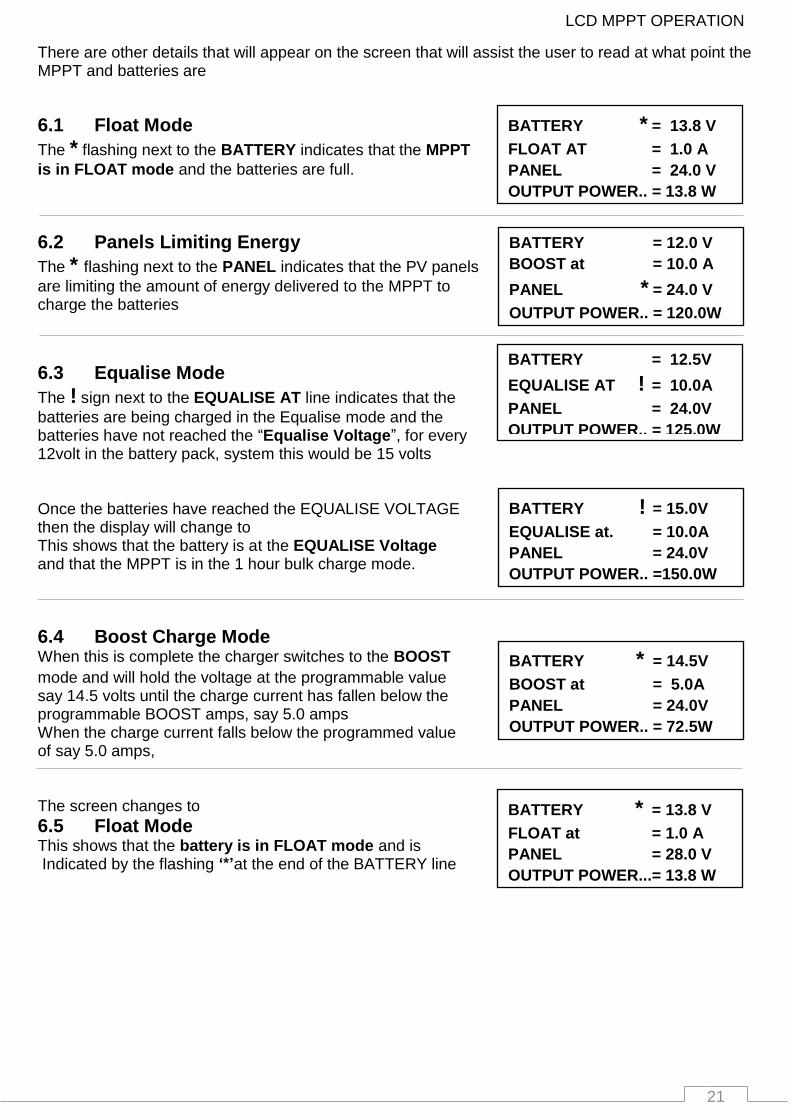
There are other details that will appear on the screen that will assist the user to read at what point the MPPT and batteries are
6.1 Float Mode
The * flashing next to the BATTERY indicates that the MPPT
is in FLOAT mode and the batteries are full.
6.2 Panels Limiting Energy
The * flashing next to the PANEL indicates that the PV panels
are limiting the amount of energy delivered to the MPPT to charge the batteries
6.3 Equalise Mode
The ! sign next to the EQUALISE AT line indicates that the
batteries are being charged in the Equalise mode and the batteries have not reached the “Equalise Voltage”, for every 12volt in the battery pack, system this would be 15 volts Once the batteries have reached the EQUALISE VOLTAGE then the display will change to This shows that the battery is at the EQUALISE Voltage and that the MPPT is in the 1 hour bulk charge mode.
6.4 Boost Charge Mode When this is complete the charger switches to the BOOST
mode and will hold the voltage at the programmable value say 14.5 volts until the charge current has fallen below the programmable BOOST amps, say 5.0 amps When the charge current falls below the programmed value of say 5.0 amps, The screen changes to
6.5 Float Mode This shows that the battery is in FLOAT mode and is Indicated by the flashing ‘*’at the end of the BATTERY line
BATTERY ! = 15.0V
EQUALISE at. = 10.0A
PANEL = 24.0V
OUTPUT POWER.. =150.0W
22
LCD MPPT OPERATION
FIRMWARE V4.55
DOC’S AND SUPPORT at
www.Microcare.CO.ZA
0: 2.234 4: 0.000
1: 0.000 5: 0.000
2: 0.000 6: 0.000
3: 0.000 7: 0.000
8 : 2.234 12: 0.000
9 : 0.000 13: 0.000
10: 0.000 14: 0.000
11: 0.000 15: 0.000
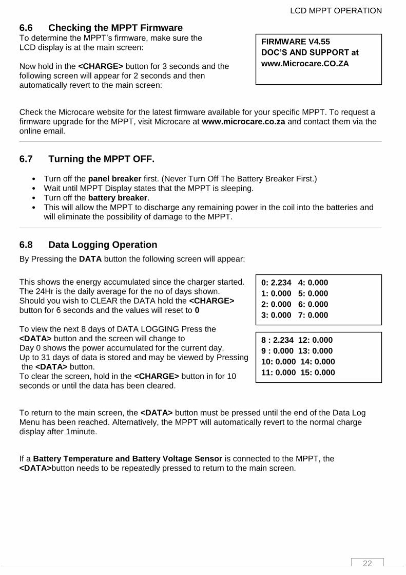
6.6 Checking the MPPT Firmware To determine the MPPT’s firmware, make sure the LCD display is at the main screen: Now hold in the <CHARGE> button for 3 seconds and the following screen will appear for 2 seconds and then automatically revert to the main screen:
Check the Microcare website for the latest firmware available for your specific MPPT. To request a firmware upgrade for the MPPT, visit Microcare at www.microcare.co.za and contact them via the online email.
6.7 Turning the MPPT OFF.
• Turn off the panel breaker first. (Never Turn Off The Battery Breaker First.) • Wait until MPPT Display states that the MPPT is sleeping. • Turn off the battery breaker. • This will allow the MPPT to discharge any remaining power in the coil into the batteries and
will eliminate the possibility of damage to the MPPT.
6.8 Data Logging Operation
By Pressing the DATA button the following screen will appear:
This shows the energy accumulated since the charger started. The 24Hr is the daily average for the no of days shown. Should you wish to CLEAR the DATA hold the <CHARGE> button for 6 seconds and the values will reset to 0 To view the next 8 days of DATA LOGGING Press the <DATA> button and the screen will change to Day 0 shows the power accumulated for the current day. Up to 31 days of data is stored and may be viewed by Pressing the <DATA> button. To clear the screen, hold in the <CHARGE> button in for 10 seconds or until the data has been cleared.
To return to the main screen, the <DATA> button must be pressed until the end of the Data Log Menu has been reached. Alternatively, the MPPT will automatically revert to the normal charge display after 1minute.
If a Battery Temperature and Battery Voltage Sensor is connected to the MPPT, the <DATA>button needs to be repeatedly pressed to return to the main screen.

23
SETUP MENU SETTINGS
FLOAT CHARGE VOLTAGE =13.8V DEFAULT
BOOST TO FLT CHANGE IF CHARGE < 6AMPS
BOOST TO FLT CHANGE INTERVAL SCAN =1HR
BOOST CHARGE VOLTAGE =14.5V DEFAULT
EQUALISE CHARGE MODE AUTO ENABLED
BATTERY PACK SELECT 12 - 48V AUTO SELECT
CHARGE LIMIT IS @ = 95%
EXTERNAL OUTPUT IS A UNUSED OUTPUT N/C
SET OPERATION MODE F MODE 0
SOLAR OR WIND MPPT? MODE = SOLAR
SET HOUR OF THE DAY = 14:00
SET MIN OF THE HOUR = 14:10
SET COMMUNICATIONS ADDRESS =
7. SETUP MENU SETTINGS
Setup Menu - Quick Reference Guide
Menu Settings
13.2V – 14.5V 0.1V Increments
13.5V – 16V 0.1v Increments
30min – 1 Hour – 2 Hours Default = 1 Hr
3 - 6 – 15 – 30 Amps Default is < 6 Amps
Auto or Manual select Default is Auto
12 – 24 - 36- 48 Default is 12 – 48V Auto Select
Adjustable in increments of 5%
Refer to Section 9
Mode 0 or Mode 1 Default=Mode 0
Solar or Wind Default=Solar for PV Panels
Sets the hours in 1 hour increments
Sets the minutes in 1 min increments
Default=5 for the first MPPT

24
Programming the MPPT
FLOAT CHARGE VOLTAGE
= 13.8v DEFAULT
press CHRG to save
press DATA to change
MICROCARE MPPT 40Amp
Panel is LOW
. . . MPPT sleeping . . .
Battery = 25.0V
8. Programming the MPPT
All settings are for 12 Volt nominal systems. Divide the required settings: / 2 for 24 Volt Systems. / 3 for 36 Volt Systems. / 4 for 48 Volt systems.
Eg: If the float voltage for a 48V system is 54,2V, the setting on the MPPT = (54,2/4) =13,8V Set the float voltage on the MPPT to 13,8V Please consult your battery supplier for the correct battery charging specifications before commencing with the MPPT programming. Incorrect charging can damage batteries. Make note of the following: Battery float voltage, boost voltage and equalisation voltage. Note that some battery types cannot be equalised.
Programming mode
To enter the programming mode the MPPT must be
connected to the batteries: The Battery Circuit Breaker must be turned ON The Panel Circuit Breaker must be turned OFF . When the Panel circuit breaker is turned off the MPPT will enter the sleep mode and the MPPT must be in SLEEP MODE to enter the programming mode Press and hold the <CHARGE> button for 6 seconds
The Screen in section 8.1 will be displayed
8.1 Float Voltage The Float voltage can be changed from 13.2 to 14.5 volts in 0.1 volt increments. Default Value is 13.8V. Obtain the correct float charge voltage from your battery supplier For a 48V battery bank with a float voltage of 54V the setting on the MPPT must be set at 13,8V
Press the <DATA> button to change the battery FLOAT VOLTAGE Press <CHARGE> to save the selected FLOAT VOLTAGE
The screen changes to: BOOST CHARGE VOLTAGE
Charge Button
Data Button

25
Programming the MPPT
BOOST CHARGE VOLTAGE
= 14.5v DEFAULT
press CHRG to save
press DATA to change
BOOST TO FLT CHANGE
INTERVAL SCAN = 1Hr
press CHRG to save
press DATA to change
BOOST TO FLT CHANGE
IF CHARGE < 3 AMPS
press CHRG to save
press DATA to change
EQUALISE CHARGE MODE
AUTO ENABLED
press CHRG to save
press DATA to change
8.2 Boost Voltage
The Boost voltage can be changed between 13.5 and 16.0 volts in 0.1 volt increments. Default Value is 14.5V. Obtain the correct boost charge voltage from your battery supplier
Press the <DATA> button to change the battery BOOST VOLTAGE Press <CHARGE> to save the setting
The screen changes to: BOOST TO FLOAT CHANGE
8.3 Boost to Float Voltage This screen changes the time that the BOOST mode takes to switch to FLOAT mode, once the batteries have reached the BOOST voltage level.
The time can be set to 30minutes – 1 hour – 2 hours.
Default Value is 1 Hr.
Press the <DATA> button to change the battery BOOST VOLTAGE Press <CHARGE> to save
The screen changes to: BOOST TO FLOAT CURRENT
8.4 Boost to Float Current This changes the charge current at which the BOOST mode after timing out, changes to FLOAT.
• This can be <3 – <6 – <15 - <30 amps or Disabled. • Default Value is < 6 Amps
Press the <DATA> button to change the battery BOOST TO FLOAT CURRENT VOLTAGE Press the <CHARGE> button to save the setting
The screen changes to EQUALISE CHARGE MODE
.
8.5 Equalise Charge Mode In this mode the Regulator will automatically go into EQUALISE mode if the battery pack voltage falls below 10.8V. This enables or disables the EQUALISE Charge mode.
• Auto= 1 Every forth-night (+- 2 weeks) • Manual = Disable ) Selected by Pressing the charge
button) • Default Value is AUTO.
The MPPT will automatically set the Equalisation voltage
EQ: = 15V if boost voltage setting is 14,7V or lower
EQ: = 16V if boost voltage setting is 14,8V or higher
To change the battery EQUALISE CHARGE MODE press the <DATA> button To save the setting press the <CHARGE> button
PLEASE NOTE: Some battery types cannot undergo an equalisation charge. Contact you battery supplier for the correct charging information.
The display changes to: BATTERY PACK SELECT
26
Programming the MPPT
BATTERY PACK SELECT
12 – 48 AUTO SELECT
press CHRG to save
press DATA to change
CHARGE LIMIT IS @
= 95%
press CHRG to save
press DATA to change
EXTERNAL OUTPUT IS A
UNUSED OUTPUT N/C
press CHARGE to save
press DATA to change
SET OPERATION MODE
F MODE0
press CHRG to save
press DATA to change
SOLAR OR WIND MPPT ?
MODE = SOLAR
press CHRG to save
press DATA to change
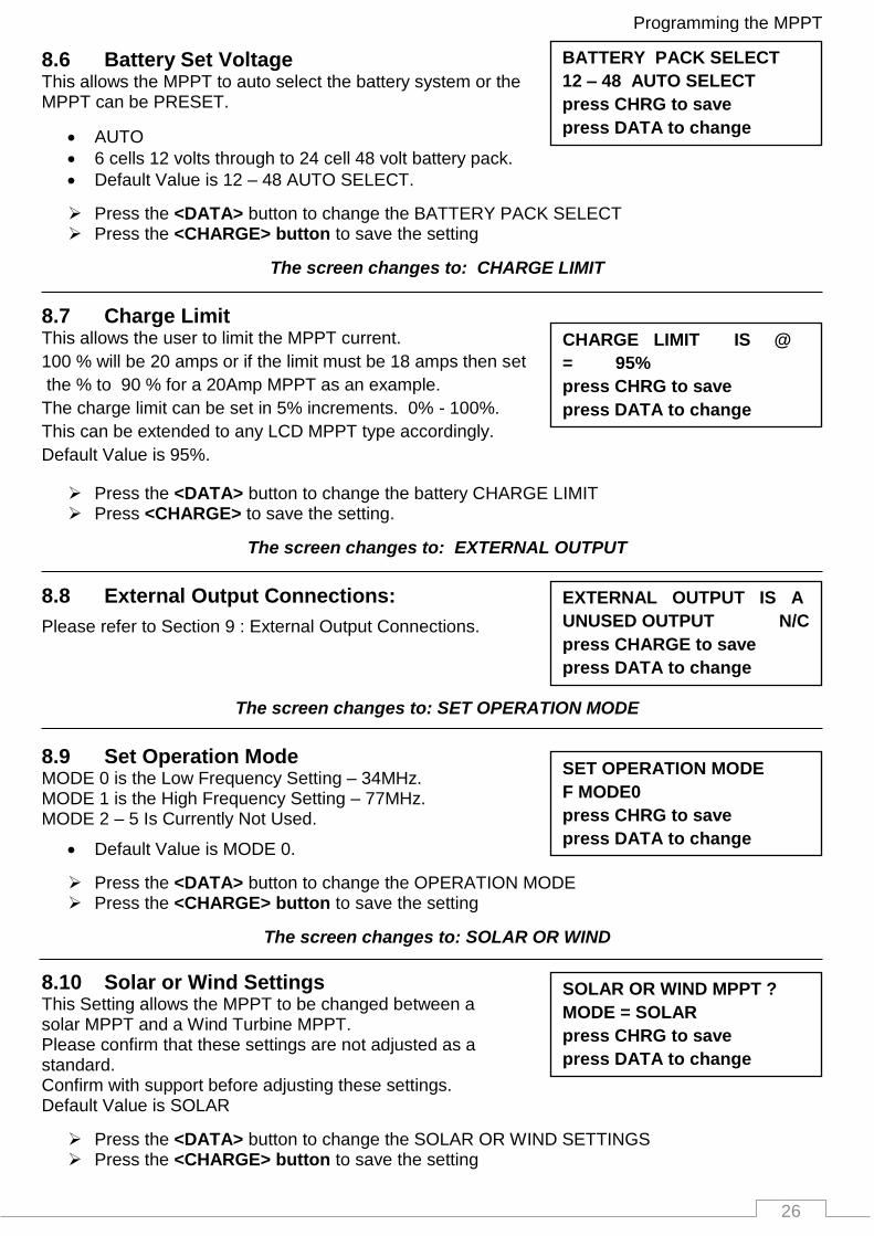
8.6 Battery Set Voltage This allows the MPPT to auto select the battery system or the MPPT can be PRESET.
AUTO
6 cells 12 volts through to 24 cell 48 volt battery pack.
Default Value is 12 – 48 AUTO SELECT.
Press the <DATA> button to change the BATTERY PACK SELECT Press the <CHARGE> button to save the setting
The screen changes to: CHARGE LIMIT
8.7 Charge Limit This allows the user to limit the MPPT current.
100 % will be 20 amps or if the limit must be 18 amps then set
the % to 90 % for a 20Amp MPPT as an example.
The charge limit can be set in 5% increments. 0% - 100%.
This can be extended to any LCD MPPT type accordingly.
Default Value is 95%.
Press the <DATA> button to change the battery CHARGE LIMIT Press <CHARGE> to save the setting.
The screen changes to: EXTERNAL OUTPUT
8.8 External Output Connections:
Please refer to Section 9 : External Output Connections.
The screen changes to: SET OPERATION MODE
8.9 Set Operation Mode MODE 0 is the Low Frequency Setting – 34MHz. MODE 1 is the High Frequency Setting – 77MHz. MODE 2 – 5 Is Currently Not Used.
Default Value is MODE 0.
Press the <DATA> button to change the OPERATION MODE Press the <CHARGE> button to save the setting
The screen changes to: SOLAR OR WIND
8.10 Solar or Wind Settings This Setting allows the MPPT to be changed between a solar MPPT and a Wind Turbine MPPT. Please confirm that these settings are not adjusted as a standard. Confirm with support before adjusting these settings. Default Value is SOLAR
Press the <DATA> button to change the SOLAR OR WIND SETTINGS Press the <CHARGE> button to save the setting

27
EXTERNAL CONNECTIONS
SET HOUR OF THE DAY
= 14: 40
press CHRG to save
press DATA to change
SET MIN OF THE HOUR
= 14: 40
press CHRG to save
press DATA to change
EXTERNAL OUTPUT IS A
UNUSED OUTPUT N/C
press CHARGE to save
press DATA to change
EXTERNAL OUTPUT IS A
UNUSED OUTPUT N/C
press CHARGE to save
press DATA to change
The screen changes to: SET HOUR OF THE DAY
8.11 Change time settings
This allows the user to change the time settings of the MPPT. The Hour of the day is changed in this screen through a 24hour time format with 1 hour increments. Press the <DATA> button to change the HOUR OF THE DAY SETTINGS Press the <CHARGE> button to save the setting
The screen changes to: SET MIN OF THE HOUR
In this screen, the clock’s minutes are adjusted in a similar way to that of the hour settings. Press <DATA> button to change the MIN OF THE
HOUR SETTINGS Press the <CHARGE> button to save the setting
Note: Time settings do not affect any MPPT operations and are purely for user convenience. Time settings are lost when the batteries are disconnected from the MPPT
The screen changes to: SET COMMUNICATIONS ADRESS
8.12 Communication Setting
Only to be adjusted when communicating to a Web Logger or our Battery Monitor system and using more than 1 x MPPT for communication.
Default Address:= 5
5 for the 1st MPPT, 6 = 2nd MPPT, 7= 3rd MPPT etc. “Max of 20 x MPPT’s”, Do not use Address 0 – 5, Address “5” will be the default for the 1st MPPT. Press the <DATA> button to Communication Address Press the <CHARGE> button to save the setting
The screen changes to: EXTERNAL CONNECTIONS
9. EXTERNAL CONNECTIONS
This allows the user to program the external output to operate a MICROACRE PROGRAMABLE RELAY INTERFACE. This is plugged into the RJ12 port.
Pressing the <DATA> button will change the external output from an UNUSED output to a:
1. SOLAR ASSIST SIGNAL 2. DAY NIGHT no L-S SIGNAL ( L-S = Load Shed )
Load switches on at dawn with no load shed 3. LOAD SHED SIGNAL also known as a (Low Battery
Disconnect) 4. SOLAR ASSIST SIGNAL V2 5. SOLAR AST UPS CNTR1 6. WIND TURBINE BRAKE (Contact our Support team regarding this option)
SET COMMUNICATIONS
ADDRESS = 5
press CHRG to save
press DATA to change
28
EXTERNAL CONNECTIONS
EXTERNAL OUTPUT IS A
LOAD SHED DISCONNECT
press CHARGE to save
press DATA to change
LOAD DISCONNECTING @
= 11.0V PER BAT PACK
press CHARGE to save
press DATA to change
LOAD RECONNECTING @
= 13.0V PER BAT PACK
press CHARGE to save
press DATA to change
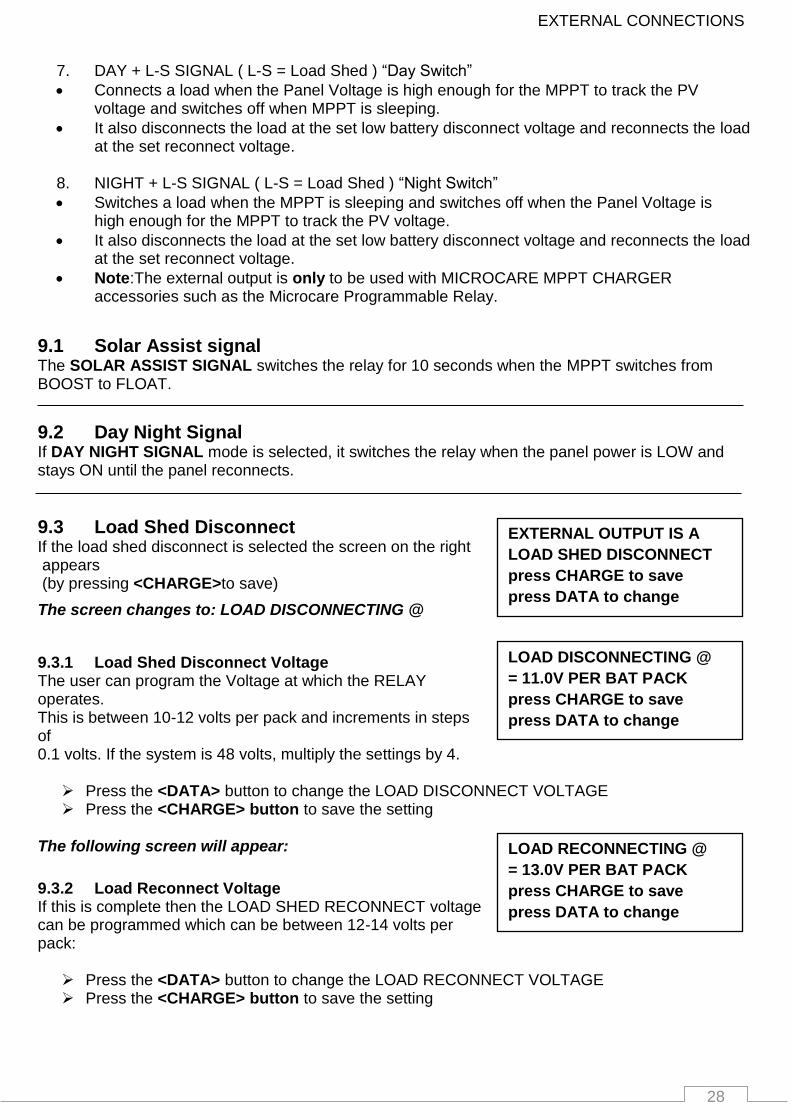
7. DAY + L-S SIGNAL ( L-S = Load Shed ) “Day Switch”
Connects a load when the Panel Voltage is high enough for the MPPT to track the PV voltage and switches off when MPPT is sleeping.
It also disconnects the load at the set low battery disconnect voltage and reconnects the load at the set reconnect voltage.
8. NIGHT + L-S SIGNAL ( L-S = Load Shed ) “Night Switch”
Switches a load when the MPPT is sleeping and switches off when the Panel Voltage is high enough for the MPPT to track the PV voltage.
It also disconnects the load at the set low battery disconnect voltage and reconnects the load at the set reconnect voltage.
Note:The external output is only to be used with MICROCARE MPPT CHARGER accessories such as the Microcare Programmable Relay.
9.1 Solar Assist signal The SOLAR ASSIST SIGNAL switches the relay for 10 seconds when the MPPT switches from BOOST to FLOAT.
9.2 Day Night Signal If DAY NIGHT SIGNAL mode is selected, it switches the relay when the panel power is LOW and stays ON until the panel reconnects.
9.3 Load Shed Disconnect If the load shed disconnect is selected the screen on the right appears (by pressing <CHARGE>to save)
The screen changes to: LOAD DISCONNECTING @
9.3.1 Load Shed Disconnect Voltage The user can program the Voltage at which the RELAY operates. This is between 10-12 volts per pack and increments in steps of 0.1 volts. If the system is 48 volts, multiply the settings by 4. Press the <DATA> button to change the LOAD DISCONNECT VOLTAGE Press the <CHARGE> button to save the setting
The following screen will appear:
9.3.2 Load Reconnect Voltage If this is complete then the LOAD SHED RECONNECT voltage can be programmed which can be between 12-14 volts per pack: Press the <DATA> button to change the LOAD RECONNECT VOLTAGE Press the <CHARGE> button to save the setting

29
EXTERNAL CONNECTIONS
EXTERNAL OUTPUT IS A
LOAD SHED DISCONNECT
press CHARGE to save
press DATA to change
LOAD DISCONNECTING @
= 11.0V PER BAT PACK
press CHARGE to save
press DATA to change
LOAD RECONNECTING @
= 13.0V PER BAT PACK
press CHARGE to save
press DATA to change
REMOTE BVT CONNECTED
VOLTAGE MPPT = xx.xV
BV= 0.00V ADJ- xx.xV
BT=25.0’C ADJ+ xx.xV
DO NOT PREES BOTH
DATA and MODE buttons
AT THE SAME TIME
MPPT WILL STOP IN 100
The SOLAR ASSIST SIGNAL V2 switches the relay for 10 seconds when the battery voltage is
limiting the current into the system. This is when the * is flashing next to the Battery display.
If SOLAR AST UPS CNTR1 is selected
(by pressing <CHARGE> to save).
The following screen will appear:
The user can program the Voltage at which the RELAY operates. This is between 10-12 volts per pack, in 0.1 volt steps. If the system is 48 volts multiply the settings by 4.
If this is complete then the LOAD RELAY RECONNECT voltage may be programmed which can be between 12-14 volts per pack.
9.4 Battery Temp and Battery Voltage Sensor
When the sensor is plugged into the RJ12 connector then the following screen will show: This shows the battery temperature and voltage. Should there be a problem with the cable or a poor connection then the screen will flash ERROR. Voltage MPPT shows the battery voltage at the output of the MPPT. The BV shows the voltage at the battery terminals. The correction is shown as either +/-. The Battery Temperature (BT) is then shown with the ADJ compensation. If the Battery Voltage Temperature is disconnected, the MPPT will revert back to stand alone readings.
9.5 To reset the MPPT to factory defaults
To reset the MPPT to factory defaults you need to make sure the MPPT Battery and Panel Breaker is off.
Press and hold the DATA and CHARGE Button and turn on the battery breaker.
The following screen will appear Once the countdown completes then the MPPT will have been reset to the default values. Switch off the battery breaker and restart the MPPT.
30
TROUBLESHOOTING
. . . WARNING . . . HIGH PANEL VOLTAGE V POWER POINT = xV
ERR DETECTED! PANEL
OPEN CIRCUIT VOLTAGE
GREATER THAN 150 VDC
MPPT CHARGE DISABLED
BATTERY = 13.8V
BOOST at = LOW
PANEL = 28.0V
OUTPUT POWER = LOW
ERR DETECTED! BATTERY
OPEN CIRCUIT VOLTAGE
GREATER THAN 60vDC
MPPT CHARGE DISABLED
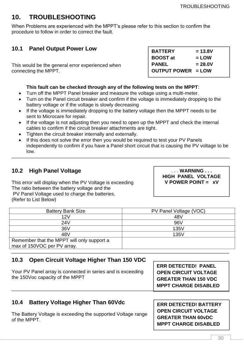
10. TROUBLESHOOTING
When Problems are experienced with the MPPT’s please refer to this section to confirm the procedure to follow in order to correct the fault.
10.1 Panel Output Power Low
This would be the general error experienced when connecting the MPPT.
This fault can be checked through any of the following tests on the MPPT:
Turn off the MPPT Panel breaker and measure the voltage using a multi-meter.
Turn on the Panel circuit breaker and confirm if the voltage is immediately dropping to the battery voltage or if the voltage is slowly decreasing
If the voltage is immediately dropping to the battery voltage then the MPPT needs to be sent to Microcare for repair.
If the voltage is not adjusting then you need to open up the MPPT and check the internal cables to confirm if the circuit breaker attachments are tight.
Tighten the circuit breaker internally and externally.
If this does not solve the error then you would be required to test your PV Panels independently to confirm if you have a Panel short circuit that is causing the PV voltage to be low.
10.2 High Panel Voltage This error will display when the PV Voltage is exceeding The ratio between the battery voltage and the PV Panel Voltage used to charge the batteries. (Refer to List Below)
Battery Bank Size PV Panel Voltage (VOC)
12V 48V
24V 96V
36V 135V
48V 135V
Remember that the MPPT will only support a max of 150VOC per PV array.
10.3 Open Circuit Voltage Higher Than 150 VDC Your PV Panel array is connected in series and is exceeding the 150Voc capacity of the MPPT
10.4 Battery Voltage Higher Than 60Vdc The Battery Voltage is exceeding the supported Voltage range of the MPPT.
31
Maintenance and service
ERR DETECTED!
MPPT OUTPUT
SHORT CIRCUIT
MPPT CHARGE DISABLED
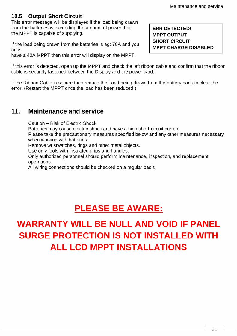
10.5 Output Short Circuit This error message will be displayed if the load being drawn from the batteries is exceeding the amount of power that the MPPT is capable of supplying. If the load being drawn from the batteries is eg: 70A and you only have a 40A MPPT then this error will display on the MPPT. If this error is detected, open up the MPPT and check the left ribbon cable and confirm that the ribbon cable is securely fastened between the Display and the power card. If the Ribbon Cable is secure then reduce the Load being drawn from the battery bank to clear the error. (Restart the MPPT once the load has been reduced.)
11. Maintenance and service
Caution – Risk of Electric Shock. Batteries may cause electric shock and have a high short-circuit current. Please take the precautionary measures specified below and any other measures necessary when working with batteries. Remove wristwatches, rings and other metal objects. Use only tools with insulated grips and handles. Only authorized personnel should perform maintenance, inspection, and replacement operations. All wiring connections should be checked on a regular basis
PLEASE BE AWARE:
WARRANTY WILL BE NULL AND VOID IF PANEL
SURGE PROTECTION IS NOT INSTALLED WITH
ALL LCD MPPT INSTALLATIONS
32
LCD MPPT SPECIFICATIONS
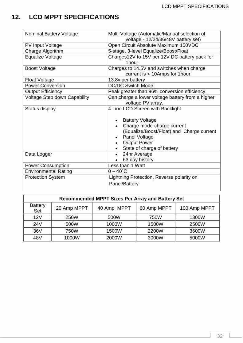
12. LCD MPPT SPECIFICATIONS
Recommended MPPT Sizes Per Array and Battery Set
Battery Set
20 Amp MPPT 40 Amp MPPT 60 Amp MPPT 100 Amp MPPT
12V 250W 500W 750W 1300W
24V 500W 1000W 1500W 2500W
36V 750W 1500W 2200W 3600W
48V 1000W 2000W 3000W 5000W
Nominal Battery Voltage Multi-Voltage (Automatic/Manual selection of voltage - 12/24/36/48V battery set)
PV Input Voltage Open Circuit Absolute Maximum 150VDC
Charge Algorithm 5-stage, 3-level Equalize/Boost/Float
Equalize Voltage Charges12V to 15V per 12V DC battery pack for 1hour
Boost Voltage Charges to 14.5V and switches when charge current is < 10Amps for 1hour
Float Voltage 13.8v per battery
Power Conversion DC/DC Switch Mode
Output Efficiency Peak greater than 96% conversion efficiency
Voltage Step down Capability Can charge a lower voltage battery from a higher voltage PV array.
Status display 4 Line LCD Screen with Backlight
Battery Voltage Charge mode-charge current
(Equalize/Boost/Float) and Charge current Panel Voltage Output Power State of charge of battery
Data Logger 24hr Average 63 day history
Power Consumption Less than 1 Watt
Environmental Rating 0 – 40˚C
Protection System Lightning Protection, Reverse polarity on
Panel/Battery

33
LCD MPPT ACCESSORIES
13. LCD MPPT ACCESSORIES
13.1 Data acquisition software
13.2 Battery Monitor
13.3 Battery Monitor Accessories 13.3.1 100 A Battery Sensor 13.3.2 200 A Battery Sensor 13.3.3 400 A Battery Sensor 13.3.4 Web-Logger 13.3.5 232-485 Converter
13.4 Programmable Relay
13.5 PV String Combiner and Surge Protection Box Available in multiple configurations
34
DESTRIER ELECTRONICS LIMITED CARRY- IN WARRANTY
14. DESTRIER ELECTRONICS LIMITED CARRY- IN WARRANTY
Destrier Electronics warrants the full range of LCD MPPT’s against defects in workmanship and materials, fair wear and tear accepted, for a period of 3 (three) years from the date of delivery/collection for all equipment and is based on a carry-in basis. Where the installation of the product makes it impractical to carry-in to our workshops, Destrier Electronics reserves the right to charge for travel time and kilometres travelled to and from the site where the product is installed.
During this warranty period, Destrier Electronics will, at its own discretion, repair or replace the defective product free of charge. This warranty will be considered void if the unit has suffered any physical damage or alteration, either internally or externally, and does not cover damages arising from improper use such as, but not exclusive to:
• Reverse of battery polarity. • Inadequate or incorrect connection of the product and/or of its accessories. • Mechanical shock or deformation. • Contact with liquid or oxidation by condensation. • Use in an inappropriate environment (dust, corrosive vapour, humidity, high temperature,
biological infestation.)
• Breakage or damage due to lightning, surges, spikes or other electrical events. • Connection terminals and screws destroyed or other damage such as overheating due to
insufficient tightening of terminals. • When considering any electronic breakage except due to lightning, reverse polarity, over-
voltage, etc. the state of the internal control circuitry determines the warranty.
This warranty will not apply where the product has been misused, neglected, improperly installed, or repaired by anyone else than Destrier Electronics or one of its authorised Qualified Service Partners. In order to qualify for the warranty, the product must not be disassembled or modified. Repair or replacement is our sole remedy. Destrier Electronics shall not be liable for damages, whether direct, incidental, special, or consequential, even caused by negligence or fault. Destrier Electronics owns all parts removed from repaired products. Destrier Electronics uses new or re-conditioned parts made by various manufacturers in performing warranty repairs and building replacement products. If Destrier Electronics repairs or replaces a part of a product, its warranty term is not extended. Removal of serial nos. may void the warranty.
All remedies and the measure for damages are limited to the above. Destrier Electronics shall in no event be liable for consequential, incidental, contingent or special damages, even if having been advised of the probability of such damages. Any and all other warranties expressed or implied arising by law, course of dealing, course of performance, usage of trade or otherwise, including but not limited to implied warranties of merchantability and fitness for a particular purpose, are limited in duration to a period of 3 (three) years from the date of purchase.
Life Support Policy: As a general policy, Destrier Electronics does not recommend the use of any of its products in life support applications where failure or malfunction of the Destrier Electronics product can be reasonably expected to cause failure of the life support device or to significantly affect its safety or effectiveness.
Destrier Electronics does not recommend the use of any of its products in direct patient care. Destrier Electronics will not knowingly sell its products for use in such applications unless it receives in writing assurances satisfactory to Destrier Electronics that the risks of injury or damage have been minimised, the customer assumes all such risks, and the Liability of Destrier Electronics is adequately protected under the circumstances.
Caution: Our products are sensitive. While all care is taken by us to dispatch goods with adequate packaging, Destrier Electronics is not responsible for any damages caused to products after they have left our premises.

35
15. REGISTRATION OF MY MICROCARE PRODUCT Please register your product online at www.microcare/register-my-product
Also complete the form below as a hardcopy reference for technical support.
Product Serial Number: Product Description: Date Purchased
Where was the product was purchased.
Company Name Contact Person Contact Number E-mail Address
Installation Company Information:
Company Name Contact Person Contact Number E-mail Address
Details of Product Owner Name & Surname Address City & Province Contact Number E-mail Address Date Installed Microcare: 1st Floor, Neave Industrial Park, Korsten, Port Elizabeth P.O.Box 7227, Newton Park, 6055 Tel: 041 453 5761, Fax: 041 – 453 5763 Technical Support e-mail: [email protected] Website: www.microcare.co.za Registration by fax: 041 – 453 5763 Registration by e-mail: [email protected]/register-my-product


