LCH V LCH V LCH V LCH V REFROIDISSEURS DE LIQUIDE MONOBLOC à condensation par air équipés de compresseur à vis PACKAGED LIQUID CHILLERS with air cooled condenser and screw type compressors PUISSANCE FRIGORIFIQUE NOMINALE NOMINAL COOLING CAPACITY 205 kW L 1403 kW LCH V avec option sectionneur général LCH V unit with main switch option
Transcript
LCH VLCH VLCH VLCH V
REFROIDISSEURS DE LIQUIDE MONOBLOCà condensation par air
La fabrication des refroidisseurs LCH V répond au système de contrôle qualité ISO9001. Une copie du certificat peut être obtenue sur simple demande.
The manufacturing of LCH V chillers answers to ISO 9001 control quality system. Acopy of the certificat can be get on request.
DC/LCH V • 3 •
Les nouveaux refroidisseurs de liquide LCH V s'intè-grent parfaitement dans notre gamme complète desystème HVAC "Chauffage - Ventilation - Condition-nement d'air".
La fabrication des refroidisseurs LCH V est conformeaux normes européennes et répond au système decontrôle qualité ISO 9001.
Afin de s'assurer de la conformité finale du produitavec la commande du client et du parfait fonctionne-ment électrique et frigorifique, les refroidisseursLCH V sont systématiquement testés en station d'es-sai avant leur expédition.
Compacts et silencieux, les refroidisseurs LCH Vbénéficient des meilleures technologies pour répon-dre aux exigences de fiabilité et de sécurité.
COMPRESSEUR- Type semi-hermétique à vis- Moteur incorporé refroidi par les gaz aspirés- Régulation de puissance intégrée sans contact avec les vis :
proportionnelle de 45 à 100% par compresseur- Résistance de réchauffage carter- Dispositif anti-court cycle- Protection électronique du moteur- Démarrage Etoile/Triangle- Clapet d'aspiration- Vanne d'isolement au refoulement- Montage sur plots antivibratiles en polyéthéruréthane cel-
lulaire haute efficacité
EVAPORATEUR- Faisceau en U, démontable, constitué de tubes rainurés
intérieur dudgeonnés dans une plaque tubulaire en acieravec chicanes en laiton, logé dans une enveloppe en acier
- Purge d'air et purge d'eau- Isolation thermique par mousse à cellule fermée, épaisseur
12,7 mm, et colle pare vapeur
CONDENSEUR A AIR- Batteries tubes cuivre rainurés, ailettes aluminium haute
performance- Ventilateurs hélicoïdes- Accouplement direct
ACCESSOIRES FRIGORIFIQUES- Filtre désydrateur à cartouche démontable- Voyant liquide indicateur d'humidité- Capteurs haute et basse pression- Détendeur électronique- Electrovanne liquide- Soupape de sécurité HP- Système économiseur
ARMOIRE ELECTRIQUE- Etanchéité IP55, ventilée, avec portes sur charnières- Alimentation 400V/3/50 Hz + T- Tension de contrôle 230V/1/50 Hz (générée par le transfor-
mateur de contrôle)- Alimentation séparée 230V/3/50 Hz (à prévoir pour les
résistances de carter)- Interrupteur de mise sous tension du circuit de commande- Câblage conforme à la norme EN 60204
The new LCH V liquid chillers perfectly combine withour complete range of HVAC system.
The manufacturing of LCH V chillers complies withthe European standards and answers to ISO 9001control quality system.
In order to meet the final conformity of finished productwith the customers' order and the perfect refrigerationand electrical operation of the unit as well, the LCH Vchillers are systematically tested in the test stationbefore sending.
Compact and silent, the LCH V liquid chillers benefitfrom the best technological developments to answerto reliability and safety requirements.
COMPRESSOR- Semi-hermetic screw type- Suction gas cooled integral motor- Integral capacity control without screw contact : proportional
from 45 to 100% per compressor- Crankcase heater- Anti short cycle system- Electronic motor protection- Star/Delta start- Suction valve- Discharge isolation valve- Mounted on high efficiency cellular polyurethane vibration
absorbers
EVAPORATOR- Removable U shaped bundle, made of internal tubes
expanded into a steel tubular sheet, with brass baffles,located in a steel shell.
- Air vent and water drain- Thermal insulation by top grade plastic foam (thickness
12.7 mm) and steam resistant glue
AIR COOLED CONDENSER- Slotted copper tubes coils, high efficiency aluminium fins
- Propeller fans- Direct drive
COOLING ACCESSORIES- Core filter drier- Liquid sight glass with humidity indicator- HP & LP pressure sensors- Electronic expansion valve- Liquid line solenoid valve- HP pressure gauge- Economizer cycle
ELECTRIC PANEL- IP 55 watertightness, hinged doors- Power source supply 400V/3/50 Hz + T- Control circuit power supply 230V/1/50 Hz (generated by
control transformer)- Separated supply 230V/3/50 Hz (crankcase heaters)
- Control circuit power switch- Unit wiring in compliance with standard EN 60204
PRESENTATION - DESCRIPTIF DES COMPOSANTSINTRODUCTION - DESCRIPTION OF COMPONENTS
• 4 • DC/LCH V
CHASSIS- Châssis rigide galvanisé à chaud par immersion- Peinture polyester - Couleur RAL 9002 sur panneaux,
bandeaux et viroles de ventilateurs/RAL 7032 sur armoireélectrique
- Grille de protection des batteries verticales- Manutention par le châssis
REGULATION- Commande et contrôle par microprocesseur CLIMATIC- Afficheur alphanumérique- Gestion de 256 variables- Lecture des températures d’eau, d’air et du réfrigérant- Lecture des pressions du réfrigérant- Signalisation et lecture des alarmes- Diagnostic par circuit- Réglage des consignes de température et des paramètres
adaptés aux conditions de fonctionnement- Compteurs horaires et équilibrage des temps de fonction-
nement pour chaque compresseur par permutation auto-matique
- Renvoi défaut général- Décalage du point de consigne à distance (option)- Régulation de puissance en fonction de la température de
retour d’eau avec compensation par la température dedépart
- Protection antigel
OPTIONS FRIGORIFIQUES- Contrôleur de débit d'eau glacée- Manomètre haute et basse pression- Fonctionnement toutes saisons- Résistance antigel évaporateur- Isolation évaporateur renforcée (épaisseur 2 x 12,7 mm)- Délestage HP- Grille anti-intrusion
OPTIONS ELECTRIQUES- Tension de contrôle 110V/1/50Hz ou 24V/1/50Hz- Interrupteur général de puissance
OPTIONS SILENCE- Capotage des compresseurs par mousse phonique absor-
bante + ventilation 540 tr/mn
OPTION HAUTE TEMPERATURE- Ventilation 950 tr/mn
CHASSIS- Rigid, hot dipped galvanised chassis- Polyester paint - Colour RAL 9002 on sheet metal panels
and fans/RAL 7032 on electrical panel
- Vertical coils suction grille- Unit lifting and handling via the chassis
CONTROL- Control and check by CLIMATIC microprocessor- Alpha-numerical display- Direct reading of 256 data- Reading of water, air and refrigerant temperature- Reading of refrigerant pressures- Alarm signalling and reading- Diagnostic by circuit- Adjustment of temperature setpoints and parameters
adapted to operating conditions- Hour counter and daily balance of operating time for each
compressor by automatic permutation
- Remote default signal- Remote setpoint set-back (option)- Capacity control in accordance with water inlet temperature
with balancing by outlet temperature
- Anti freeze protection
REFRIGERATING OPTIONS- Chilled water flow switch- High and low pressure gauge- All season operation- Evaporator antifreeze heater- Re-inforced evaporator insulation (thickness 2 x 12,7 mm)- High pressure offloading- Anti-intrusion grille
ELECTRICAL OPTIONS- 110V/1/50Hz or 24V/1/50Hz control power- Main isolator
LOW NOISE OPTIONS- Compressor noise insulation by sound-proofing foam +
ventilation 540 RPM
HIGH TEMPERATURE OPTION- Ventilation 950 RPM
L C H 37 2 V
"V" Compresseur à visScrew type compressor
Nombre de circuitsNumber of refrigerating circuits
Dixième de la puissance nominale en kWNominal capacity expressed in tens of kW
"H" Ventilation HélicoïdeAxial fans
"C" Chiller
"L" Large (> 300 kW)
EXEMPLE DE DESIGNATION DE GAMMEEXAMPLE OF UNIT RANGE DESIGNATIONS
DC/LCH V • 5 •
Température Température entrée d'airMODELES sortie d'eau Air inlet temperature
°C 28 °C 32 °C 35 °C 39°C 43 °CMODELS Water outlet
Temperature Qo P Qo P Qo P Qo P Qo P
5 206 53,6 199 58,9 195 63,2 187 69,4 178 76,1
7 217 54,9 210 60,3 205 64,6 196 70,9 188 77,8
9 228 56,3 221 61,7 215 66,2 207 72,6 - -
5 338 86,7 327 94,2 318 100 306 108 292 116
7 356 88,7 345 96,2 336 102 322 110 309 118
9 375 90,8 364 98,4 354 104 340 112 327 121
5 409 107 398 118 388 126 373 139 355 152
7 432 110 419 120 408 129 393 142 375 156
9 455 112 441 123 429 132 413 145 - -
5 543 140 527 153 513 163 493 177 470 192
7 573 144 556 156 541 167 519 181 497 196
9 604 147 585 160 569 170 547 185 - -
5 614 160 596 176 581 189 559 208 534 228
7 648 164 628 181 612 194 587 213 563 233
9 682 169 661 185 644 198 618 218 - -
5 675 173 655 188 637 200 612 216 583 232
7 714 177 691 193 672 204 646 220 617 237
9 752 182 727 197 707 208 680 225 653 242
5 748 194 726 212 707 226 679 246 647 268
7 790 198 766 217 745 231 715 252 683 274
9 832 203 805 222 783 236 752 257 - -
5 811 213 788 234 768 251 738 276 704 303
7 856 218 831 240 809 257 776 282 743 310
9 901 224 872 245 849 263 816 289 - -
5 890 228 862 248 839 264 805 286 769 309
7 938 233 910 254 884 270 849 292 - -
9 989 239 957 260 931 276 894 298 - -
5 1012 254 981 277 955 294 917 318 876 342
7 1070 260 1037 283 1010 300 969 324 927 348
9 1130 266 1093 289 1065 306 1023 330 981 355
5 1087 281 1054 306 1025 327 985 355 938 385
7 1148 287 1112 313 1082 334 1038 362 - -
9 1211 295 1172 321 1140 341 1095 370 - -
5 1368 349 1324 379 1288 402 1235 433 1177 466
7 1445 357 1398 387 1360 410 1304 442 1246 475
9 1524 365 1473 396 1431 419 1375 451 - -
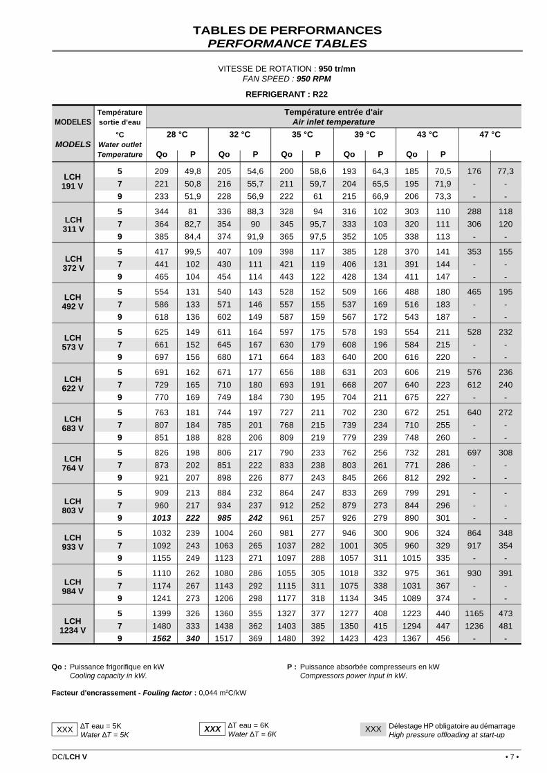
TABLES DE PERFORMANCESPERFORMANCE TABLES
Qo : Puissance frigorifique en kWCooling capacity in kW.
∆T eau = 5KWater ∆T = 5K
XXX Délestage HP obligatoire au démarrageHigh pressure offloading at start-up
XXX
P : Puissance absorbée compresseurs en kWCompressors power input in kW.
VITESSE DE ROTATION : 950 tr/mnFAN SPEED : 950 RPM
∆T eau = 6KWater ∆T = 6K
XXX
REFRIGERANT : R22
TABLES DE PERFORMANCESPERFORMANCE TABLES
• 8 • DC/LCH V
COMPRESSEURS ET CIRCUITS FRIGORIFIQUES - COMPRESSORS AND REFRIGERANT CIRCUITS
CARACTERISTIQUES TECHNIQUESTECHNICAL DA TA
EVAPORATEURS - EVAPORATORS
(1) : Brides PN 16 - PN 16 flanges
(1) : A un instant donné, un seul compresseur a l'autorisation de moduler sa puissanceAt any given time, only one compressor is allowed to operate with capacity reduction
MODELE - TYPE LCH V 191 311 372 492 573 622
Type de compresseurs Semi-hermétique à visCompressor type Semi-hermetic screw type
Nombre de compresseurs / Nombre de circuitsNumber of compressors / Number of circuits 1/1 1/1 2/2 2/2 3/3 2/2
Réduction de puissance par compresseur (1)Capacity steps for each compressor (1) % 0 - 45 è 100
Charge de réfrigérant par circuitRefrigerant charge per circuit kg 44 75 44 75+44 44 75
Charge d'huile par compresseurOil charge per compressor l 12 17 12 17+12 12 17
Résistance de carter par compresseurCrankcase heater per compressor W 53 53 53 53 53 53
MODELE - TYPE LCH V 683 764 803 933 984 1234
Type de compresseurs Semi-hermétique à visCompressor type Semi-hermetic screw type
Nombre de compresseurs / Nombre de circuitsNumber of compressors / Number of circuits 3/3 4/4 3/3 3/3 4/4 4/4
Réduction de puissance par compresseur (1)Capacity steps for each compressor (1) % 0 - 45 è 100
Charge de réfrigérant par circuitRefrigerant charge per circuit kg 75+44 44 75+44 75+88 75+44 75
Charge d'huile par compresseurOil charge per compressor l 17+12 12 17+12 17 17+12 17
Résistance de carter par compresseurCrankcase heater per compressor W 53 53 53 53 53 53
Intensité maxi par ventilateurEach fan full load current A 6,2 6,2 6,2 6,2 6,2 6,2
• 10 • DC/LCH V
PERTES DE CHARGE EVAPORATEURSEVAPORATOR PRESSURE DROPS
Puissance et intensité maximum calculées en 400V/3/50Hz pour régime maxi compresseur +12/60°CMaximum current and power calculated at 400V/3/50Hz for compressor operation at +12/60°C.
MODELE - TYPE LCH V 191 311 372 492 573 622
700 tr/mn - RPM 73 114 146 187 218 227
540 tr/mn - RPM 71 110 141 181 212 220
950 tr/mn - RPM 78 122 155 199 233 243
700 tr/mn - RPM 140 241 276 377 413 478
540 tr/mn - RPM 129 223 255 349 381 443
950 tr/mn - RPM 142 244 281 383 419 485
700 tr/mn - RPM 295 345 430 530 565 580
540 tr/mn - RPM 280 320 405 500 530 540
950 tr/mn - RPM 310 365 440 555 590 605
MODELE - TYPE LCH V 683 764 803 933 984 1234
700 tr/mn - RPM 259 291 300 343 373 454
540 tr/mn - RPM 251 282 291 331 361 440
950 tr/mn - RPM 277 310 321 368 398 486
700 tr/mn - RPM 514 549 615 721 751 953
540 tr/mn - RPM 475 507 569 665 695 883
950 tr/mn - RPM 522 558 624 733 763 967
700 tr/mn - RPM 665 700 770 825 905 1055
540 tr/mn - RPM 625 655 720 765 845 980
950 tr/mn - RPM 690 730 795 855 935 1085
Puissance maxi (kW)Maxi power (kW)
Intensité maxi (A)Maxi current (A)
Int. de démarrage Etoile-Triangle (A)Star-Delta start-up intensity
Puissance maxi (kW)Maxi power (kW)
Intensité maxi (A)Maxi current (A)
Int. de démarrage Etoile-Triangle (A)Star-Delta start-up intensity
CARACTERISTIQUES ELECTRIQUESELECTRICAL DATA
Les pertes de charge sont données à titre indicatif. Elles peuvent varier de +/-20 kPa par rapport aux courbes.En tenir compte lors de la sélection des pompes
Pressure drops are given for informations only. A tolerance of +/- 20kPa must be considered when selecting water pumps.
LCH V Courbe Débit d'eau maxiCurve Maxi water
flow ratem3/h
191 A 38,9
311 B 89,3
372 C 89,3
492 D 153,5
573 E 153,5
622 F 153,5
683 H 153,5
764 H 153,5
803 G 153,5
933 K 240,0
984 I 240,0
1234 J 240,0
DC/LCH V • 11 •
NIVEAUX SONORESNOISE LEVELS
Spectre par octave (dBA) Puissance globale PressionSpectrum per octave band (dBA) sonore à 10 m
Global sound power Sound power at 10 mLCH 63 Hz 125 Hz 250 Hz 500 Hz 1000 Hz 2000 Hz 4000 Hz 8000 Hz dBA dBA
191 V 69 79 88 90 91 89 84 77 96 64
311 V 71 81 91 93 95 94 90 79 100 68
372 V 72 82 91 93 94 92 87 80 99 67
492 V 73 83 92 95 97 95 91 81 102 69
573 V 74 84 92 94 95 94 88 81 101 68
622 V 74 84 94 96 98 97 93 82 103 70
683 V 74 85 94 96 98 96 92 82 103 70
764 V 75 85 94 96 97 95 90 83 102 69
803 V 75 85 95 97 99 98 93 83 104 71
933 V 76 86 96 98 100 99 95 84 105 71
984 V 76 86 95 98 100 98 94 84 105 70
1234 V 77 87 97 99 101 100 96 85 106 71
191 V 68 75 82 83 82 82 78 69 89 57
311 V 70 77 87 90 87 87 84 71 95 63
372 V 71 78 85 86 85 85 81 72 92 60
492 V 72 79 88 90 89 89 85 73 96 63
573 V 73 80 86 88 87 87 83 73 94 61
622 V 73 80 87 88 88 87 83 74 94 61
683 V 73 81 89 91 89 89 86 74 96 63
764 V 74 81 88 89 88 88 84 75 95 62
803 V 74 81 91 93 91 91 88 75 98 65
933 V 75 82 92 94 92 92 89 76 99 65
984 V 75 82 91 93 92 92 88 76 99 64
1234 V 76 83 93 96 93 93 90 77 101 66
191 V 71 83 94 96 97 96 91 84 102 70
311 V 73 85 97 99 100 99 94 86 105 73
372 V 74 86 97 99 100 99 94 87 106 74
492 V 75 87 99 101 102 101 96 88 107 74
573 V 76 88 99 101 102 101 96 88 107 74
622 V 76 88 100 102 103 102 97 89 108 75
683 V 77 88 100 102 103 102 97 89 108 75
764 V 77 89 100 102 103 102 97 90 109 76
803 V 77 89 101 103 104 103 98 90 109 76
933 V 78 90 102 104 105 104 99 91 110 76
984 V 78 90 102 104 105 104 99 91 110 75
1234 V 79 91 103 105 106 105 100 92 111 76
VE
NT
ILA
TIO
N 7
00 T
R/M
NF
AN
SP
EE
D 7
00 R
PM
VE
NT
ILA
TIO
N 5
40 T
R/M
N (
1)F
AN
SP
EE
D 5
40 R
PM
(1)
VE
NT
ILA
TIO
N 9
50 T
R/M
NF
AN
SP
EE
D 9
50 R
PM
Niveau de puissance globale mesuré dans les conditions de la norme ISO 3744.Global sound power level measured in compliance with ISO standard 3744.
Pression sonore en dB(A) calculée à 10 m, surface de mesure hémisphérique, en champ libre sur plan réfléchissant, donnée à titre indicatif.Seul le spectre de puissance acoustique et la valeur de puissance globale sont utilisables pour la détermination des caractéristiques depression en limite de propriété.
Sound pressure in dB(A) calculated at 10 m, with a hemispheric soud measurement surface, in a free field on a reflecting surface, is givenas a guide only.Only the sound power spectrum and the global sound power value are used in determining pressure characteristics at owner land limit.
(1) : avec isolation phonique des compresseurs (option)With optional compressor noise insulation
• 12 • DC/LCH V
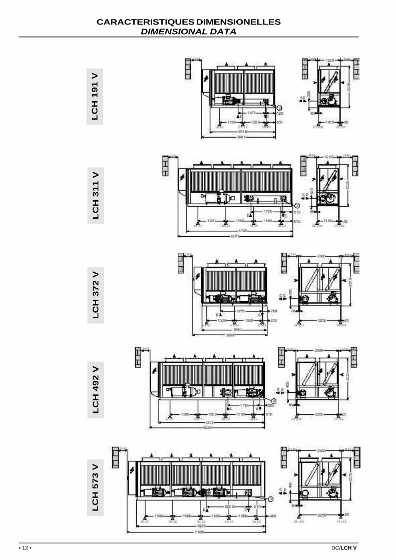
CARACTERISTIQUES DIMENSIONELLESDIMENSIONAL DATA
LC
H 1
91 V
LC
H 3
11 V
LC
H 3
72 V
LC
H 4
92 V
LC
H 5
73 V
DC/LCH V • 13 •
LC
H 9
33 V
LC
H 8
03 V
LC
H 7
64 V
LC
H 6
83 V
LC
H 6
22 V
POIDS - WEIGHTS
REPARTITIONS DE CHARGE (KG - Poids en service) - LOAD DISTRIBUTION (KG - operating weights)
MODELE - TYPE LCH V 191 311 372 492 573 622
Poids à videWeight without water kg 1760 2970 3530 4685 5455 5830
Poids en serviceOperating weight kg 1805 3045 3625 4790 5570 6010
MODELE - TYPE LCH V 683 764 803 933 984 1234
Poids à videWeight without water kg 6460 6800 7655 9455 10 725 11 640
Poids en serviceOperating weight kg 6630 6970 7860 9780 11 130 12 080
Pour plus de renseignements sur l'installation et la maintenance, se référer au manuel de mise en service.For further information regarding the installation and the maintenance, please consult user-manual.
(1) Au dessous de + 4°C, glycoler le fluide caloporteur.
(2) Valeur correspondant à la sortie d'eau glacée minimum + 4°C selonle débit considéré
(3) Correspond au débit d'eau maximum admissible à l'évaporateur
EN DEHORS DE CES VALEURS, NOUS CONSULTER.
LIMITES D'UTILISATIONOPERATING LIMITS
TEMPERATURE MAXIMUM D'AIR AMBIANT - MAXIMUM AMBIENT AIR TEMPERATURE
Température maximum d'air ambiant (°C) - Maxi ambient air temperature (°C)
Températures calculées dans les conditions de démarrage des machines, selon deux configurations :Temperature are calculated according to start-up units conditions, with two differents configurations
� LCH V standard � LCH V avec option délestage HPStandard unit LCH V unit with optional HP offloading
(1) Below +4°C, add glycol to the heating fluid.
(2) Value corresponding to the minimum of 4°C chilled water leavingtemperature at considered flow rate
(3) Corresponding to the evaporator acceptable maximum flow rate
Les caractéristiques techniques et spécifications figurant dans cette notice sont données à titre indicatif. Leconstructeur se réserve le droit de les modifier sans préavis ni obligation pour lui de modifier identiquementles matériels déjà livrés.
The specifications and technical characteristics in this booklet are given for information purposes. Themanufacturer reserves the right to modify them without prior notice or obligation to modify in a similarmanner, the equipments previously supplied.
HCF LENNOX, Division Climatisation de LGL FRANCE S.A.Siège Social : LGL FRANCE S.A. - 11, rue d'Alsace Lorraine - 69500 BRON - France